EP3617042A1 - Kraftfahrzeugstrukturbauteil - Google Patents
Kraftfahrzeugstrukturbauteil Download PDFInfo
- Publication number
- EP3617042A1 EP3617042A1 EP19185799.4A EP19185799A EP3617042A1 EP 3617042 A1 EP3617042 A1 EP 3617042A1 EP 19185799 A EP19185799 A EP 19185799A EP 3617042 A1 EP3617042 A1 EP 3617042A1
- Authority
- EP
- European Patent Office
- Prior art keywords
- structural component
- motor vehicle
- vehicle structural
- sheets
- component according
- Prior art date
- Legal status (The legal status is an assumption and is not a legal conclusion. Google has not performed a legal analysis and makes no representation as to the accuracy of the status listed.)
- Granted
Links
Images


Classifications
-
- B—PERFORMING OPERATIONS; TRANSPORTING
- B62—LAND VEHICLES FOR TRAVELLING OTHERWISE THAN ON RAILS
- B62D—MOTOR VEHICLES; TRAILERS
- B62D27/00—Connections between superstructure or understructure sub-units
- B62D27/02—Connections between superstructure or understructure sub-units rigid
- B62D27/023—Assembly of structural joints
-
- C—CHEMISTRY; METALLURGY
- C09—DYES; PAINTS; POLISHES; NATURAL RESINS; ADHESIVES; COMPOSITIONS NOT OTHERWISE PROVIDED FOR; APPLICATIONS OF MATERIALS NOT OTHERWISE PROVIDED FOR
- C09D—COATING COMPOSITIONS, e.g. PAINTS, VARNISHES OR LACQUERS; FILLING PASTES; CHEMICAL PAINT OR INK REMOVERS; INKS; CORRECTING FLUIDS; WOODSTAINS; PASTES OR SOLIDS FOR COLOURING OR PRINTING; USE OF MATERIALS THEREFOR
- C09D5/00—Coating compositions, e.g. paints, varnishes or lacquers, characterised by their physical nature or the effects produced; Filling pastes
- C09D5/08—Anti-corrosive paints
-
- B—PERFORMING OPERATIONS; TRANSPORTING
- B62—LAND VEHICLES FOR TRAVELLING OTHERWISE THAN ON RAILS
- B62D—MOTOR VEHICLES; TRAILERS
- B62D25/00—Superstructure or monocoque structure sub-units; Parts or details thereof not otherwise provided for
-
- B—PERFORMING OPERATIONS; TRANSPORTING
- B23—MACHINE TOOLS; METAL-WORKING NOT OTHERWISE PROVIDED FOR
- B23K—SOLDERING OR UNSOLDERING; WELDING; CLADDING OR PLATING BY SOLDERING OR WELDING; CUTTING BY APPLYING HEAT LOCALLY, e.g. FLAME CUTTING; WORKING BY LASER BEAM
- B23K11/00—Resistance welding; Severing by resistance heating
- B23K11/10—Spot welding; Stitch welding
- B23K11/11—Spot welding
-
- B—PERFORMING OPERATIONS; TRANSPORTING
- B62—LAND VEHICLES FOR TRAVELLING OTHERWISE THAN ON RAILS
- B62D—MOTOR VEHICLES; TRAILERS
- B62D29/00—Superstructures, understructures, or sub-units thereof, characterised by the material thereof
- B62D29/007—Superstructures, understructures, or sub-units thereof, characterised by the material thereof predominantly of special steel or specially treated steel, e.g. stainless steel or locally surface hardened steel
-
- B—PERFORMING OPERATIONS; TRANSPORTING
- B23—MACHINE TOOLS; METAL-WORKING NOT OTHERWISE PROVIDED FOR
- B23K—SOLDERING OR UNSOLDERING; WELDING; CLADDING OR PLATING BY SOLDERING OR WELDING; CUTTING BY APPLYING HEAT LOCALLY, e.g. FLAME CUTTING; WORKING BY LASER BEAM
- B23K2101/00—Articles made by soldering, welding or cutting
- B23K2101/006—Vehicles
Definitions
- the invention relates to a motor vehicle structural component made of two sheet metal plates that face one another and are connected to one another by welding points, wherein gaps are provided between the metal sheets in the areas between the welding points, into which corrosion-protective coating material can be introduced.
- a known motor vehicle structural component of the type mentioned at the beginning ( DE 10 2012 013 882 A1 ) consists of two sheets lying against each other, which are connected by a large number of welding points. Gaps remain between the two sheets, into which a coating is to be introduced as corrosion protection. The gaps have a width in the range from 0.2 mm to 0.6 mm, while the coating, which is introduced in the form of a cathodic dip coating, has a thickness of 10 to 40 ⁇ m.
- the invention is therefore based on the object of improving the known motor vehicle structural components in such a way that corrosion can no longer occur between the metal sheets connected to one another by welding points in the existing gaps.
- this object is achieved in that holes are provided in the area of the gaps for at least one of the sheets for the supply of the coating material and for ventilation.
- the coating material can easily penetrate into the gaps during the coating process due to the short distances and easy unimpeded access. At the same time, the air can escape from the gaps, so that a reliable and complete coating of the gaps can be achieved.
- the holes formed in the metal sheets can, for example, be designed as circular bores that can be easily manufactured, e.g. by punching.
- the size of the holes must be matched to the thickness of the sheets and the viscosity of the coating material.
- the holes advantageously have a diameter of approximately 2 mm to 7 mm.
- the holes have any contour. This is particularly suitable for laser-cut parts, e.g. B. Boron parts, which are often laser cut anyway.
- the holes can deviate from the circular shape and be designed in such a way that they both fulfill the drain function well and do not reduce the strength of the component or only reduce it insignificantly.
- the holes can be punched in the blank, which can result in a deviation from the circular shape after the drawing process.
- the maximum width of the holes is preferably less than 8 mm. This ensures that the irregularly shaped holes do not weaken the component too much.
- the holes are preferably formed in the sheet which lies on the side facing the inside of the vehicle. This allows the outside of the structural part to be kept smooth and closed.
- the structural components are produced in such a way that the gaps preferably have a width of approximately 0.3 mm to 0.7 mm.
- the gaps can be completely filled with the coating material, so that no unprotected residual spaces remain.
- At least one of the two sheets can have elevations on the side facing the opposite sheet close to the inlet and vent holes, so that the gaps generated are defined thereby.
- elevations can be stamped into the sheet, for example.
- the distances between the welding points are preferably approximately 25 mm to 40 mm.
- a cathodic dip coating known per se can be used as the coating material.
- At least one of the interconnected sheets or both sheets preferably consist of manganese-boron steel or boron steel, which is high-strength and slightly hot-deformable.
- the sheets can be provided with an ALSI coating, but without the additional corrosion-protective coating material, for example due to the cathodic dip coating, does not offer sufficient corrosion protection for the sheets.
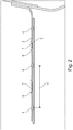
- FIGS. 1 and 2 show a motor vehicle structural component 1 according to the invention, which consists of two flat sheets 2 and 3 facing each other.
- the two sheets 2 and 3 are connected to one another by welding spots 4.
- gaps 6 are provided between the two sheets 2 and 3, which are to be better protected against corrosion by the invention.
- holes 7 are provided in the areas of column 6 in the upper sheet metal in the drawing for the feed of coating material into column 6 and for venting column 6.
- the holes 7 are designed as round bores which have a diameter of approximately 2 mm to 7 mm.
- the two sheets 2 and 3 are connected to one another in such a way that the gaps 6 have a width of about 0.3 mm to 0.7 mm, so that the penetration of the coating material into the gaps 6 can take place without problems.
- the coating material can gap 6 in view of the relatively short distances that the coating material has to travel between the sheets 2 and 3, and due to the air inclusions escaping through the holes 7 Fill in completely so that no unprotected areas remain within the column.
- the coating material when applied by cathodic dip coating, the coating material can thus penetrate into the narrowest angle of the gaps 6 without any problems.
- Fig. 1 shows, for example, the sheet 2, which is provided with the holes 7, can be provided with indentations 8 for the welding points 4.
- the distances 11 between the welding points 4 are approximately 25 mm to 40 mm, so that it is not difficult to fill the gaps 6 completely, for example in the case of electrocoating, since the distances from the holes 7 to the areas of the welding points 4 are relatively short.
- the motor vehicle structural component 1 which is composed of the two metal sheets 2 and 3, is constructed in such a way that the holes 7 are arranged in the metal sheet 2, which is directed towards the inside of the vehicle, so that the structural component 1 is closed to the outside.
- the lower sheet 3 in the drawing has elevations 9 on the side of the hole 7 in order to keep the respective gap 6 open in the region of the holes 7, so that a minimum width of the gap 6 is guaranteed and the coating material can easily penetrate into the respective gap 6 can.
- At least one of the sheets 2 and 3 is usually made of manganese-boron steel or boron steel, which has a high strength and is easy to deform.
- the sheets 2 and 3 can be provided with an ALSI coating.
Landscapes
- Engineering & Computer Science (AREA)
- Chemical & Material Sciences (AREA)
- Mechanical Engineering (AREA)
- Combustion & Propulsion (AREA)
- Transportation (AREA)
- Materials Engineering (AREA)
- Life Sciences & Earth Sciences (AREA)
- Wood Science & Technology (AREA)
- Organic Chemistry (AREA)
- Architecture (AREA)
- Structural Engineering (AREA)
- Body Structure For Vehicles (AREA)
- Resistance Welding (AREA)
- Arc Welding In General (AREA)
Abstract
Description
- Die Erfindung betrifft ein Kraftfahrzeugstrukturbauteil aus zwei flächig gegeneinander gerichteten Blechen, die durch Schweißpunkte miteinander verbunden sind, wobei zwischen den Blechen in den Bereichen zwischen den Schweißpunkten Spalte vorgesehen sind, in die korrosionsschützendes Beschichtungsmaterial einbringbar ist.
- Bei Kraftfahrzeugstrukturbauteilen, die aus zwei teilweise gegeneinander anliegenden und miteinander verbundenen Blechen bestehen, treten häufig in den Spalten zwischen den Blechen Korrosionsschäden auf, die bis zur völligen Zerstörung des jeweiligen Strukturbauteils führen können.
- Es sind in der Vergangenheit bereits erhebliche Anstrengungen unternommen worden, um derartigen Korrosionsschäden entgegenzuwirken.
- Ein bekanntes Kraftfahrzeugstrukturbauteil der eingangs genannten Art (
DE 10 2012 013 882 A1 ) besteht aus zwei gegeneinander anliegenden Blechen, die durch eine Vielzahl von Schweißpunkten miteinander verbunden sind. Zwischen den beiden Blechen verbleiben Spalte, in die als Korrosionsschutz eine Beschichtung eingebracht werden soll. Die Spalte weisen dabei eine Breite im Bereich von 0,2 mm bis 0,6 mm auf, während die Beschichtung, die in Form einer kathodischen Tauchlackierung in die Spalte eingebracht wird, eine Dicke von 10 bis 40 µm aufweist. - Eine komplette Beschichtung der Spalte zwischen den beiden durch Schweißpunkte miteinander verbundenen Blechen ist jedoch äußerst schwierig und in der Regel unvollkommen, da die Wege, die das Beschichtungsmaterial in den Spalten zwischen den Blechen zurücklegen muss, ziemlich lang sind. Darüber hinaus verhindern Lufteinschlüsse oder diverse anderweitige Hindernisse das Eindringen des Beschichtungsmaterials in die zum Teil engen Spalten. Folglich werden bei diesen bekannten Strukturbauteilen nicht die gesamten Spaltflächen zwischen den beiden Blechen durch das Beschichtungsmaterial abgedeckt, sodass verschiedene Bereiche der Spalte unbedeckt und somit ungeschützt bleiben, wodurch es trotz dieser Vorsichtsmaßnahmen zu Korrosion kommen kann.
- Der Erfindung liegt daher die Aufgabe zugrunde, die bekannten Kraftfahrzeugstrukturbauteile derart zu verbessern, dass zwischen den durch Schweißpunkte miteinander verbundenen Blechen in den vorhandenen Spalten keine Korrosion mehr auftreten kann.
- Erfindungsgemäß wird diese Aufgabe dadurch gelöst, dass im Bereich der Spalte mindestens in einem der Bleche Löcher für den Zulauf des Beschichtungsmaterials und zur Entlüftung vorgesehen sind.
- Durch das Anbringen dieser Löcher kann während des Beschichtungsvorgangs das Beschichtungsmaterial aufgrund der kurzen Wege und des leichten ungehinderten Zugangs bequem in die Spalte eindringen. Gleichzeitig kann die Luft aus den Spalten entweichen, sodass eine zuverlässige und komplette Beschichtung der Spalte erzielt werden kann.
- Die in den Blechen ausgebildeten Löcher können beispielsweise als kreisrunde Bohrungen ausgebildet sein, die sich unkompliziert herstellen lassen, z.B. durch Stanzen.
- Die Größe der Löcher ist auf die Dicke der Bleche sowie auf die Viskosität des Beschichtungsmaterials abzustimmen. Für die üblichen Anwendungsbeispiele weisen die Löcher zweckmäßig einen Durchmesser von etwa 2 mm bis 7 mm auf.
- In einer weiteren Ausführungsform weisen die Löcher eine beliebige Kontur auf. Dies eignet sich vor allem bei lasergeschnitten Teilen, z. B. bei Boron-Teilen, die oft sowieso laserbeschnitten werden. Dabei können die Löcher von der Kreisform abweichen und so gestaltet sein, dass sie sowohl die Ablauffunktion gut erfüllen als auch die Festigkeit des Bauteils nicht oder nur unwesentlich reduzieren. Alternativ können die Löcher schon im Platinenschnitt gestanzt werden, wodurch sich nach dem Ziehvorgang eine Abweichung von der Kreisform ergeben kann.
- Bevorzugt ist die maximale Weite der Löcher kleiner 8 mm. Damit wird sichergestellt, dass auch die unregelmäßig geformten Löcher das Bauteil nicht zu sehr schwächen.
- Vorzugsweise sind die Löcher in demjenigen Blech ausgebildet, welches auf der zur Fahrzeuginnenseite gerichteten Seite liegt. Dadurch kann die Außenseite des Strukturteils glatt und verschlossen gehalten werden.
- Die Strukturbauteile werden in der Weise hergestellt, dass die Spalte vorzugsweise eine Breite von etwa 0,3 mm bis 0,7 mm aufweisen.
- Aufgrund der vorhandenen Zulauf- und Entlüftungslöcher können die Spalte komplett mit dem Beschichtungsmaterial ausgefüllt werden, sodass keine ungeschützten Resträume übrigbleiben.
- Mindestens eines der beiden Bleche kann auf der dem gegenüberliegenden Blech zugewandten Seite nahe den Zulauf- und Entlüftungslöchern Erhebungen aufweisen, sodass dadurch die erzeugten Spalte definiert werden.
- Diese Erhebungen können beispielsweise in das Blech eingeprägt werden.
- Die Abstände zwischen den Schweißpunkten untereinander betragen vorzugsweise etwa 25 mm bis 40 mm.
- Als Beschichtungsmaterial kann eine an sich bekannte kathodische Tauchlackierung verwendet werden.
- Mindestens eines der miteinander verbundenen Bleche oder auch beide Bleche bestehen vorzugsweise aus Mangan-Bor-Stahl bzw. Bor-Stahl, welches hochfest und leicht warm verformbar ist.
- Die Bleche können mit einer ALSI-Beschichtung versehen sein, die aber ohne das zusätzliche korrosionsschützende Beschichtungsmaterial, beispielsweise durch die kathodische Tauchlackierung, keinen ausreichenden Korrosionsschutz für die Bleche bietet.
- Die Erfindung ist in der Zeichnung beispielhaft dargestellt und im Einzelnen anhand der Zeichnung beschrieben. Es zeigen:
- Fig. 1:
- die Ansicht eines Kraftfahrzeugstrukturbauteils,
- Fig. 2:
- in vergrößertem Maßstab einen Schnitt entlang der Linie II-II aus
Fig. 1 , - Fig. 3:
- die Herstellung von Erhebungen an einem der Bleche durch Prägung und
- Fig. 4:
- einen ähnlichen Schnitt wie
Fig. 2 mit den vorhandenen Erhebungen. - Die
Figuren 1 und2 zeigen ein erfindungsgemäßes Kraftfahrzeugstrukturbauteil 1, welches aus zwei flächig gegeneinander gerichteten Blechen 2 und 3 besteht. Die beiden Bleche 2 und 3 sind durch Schweißpunkte 4 miteinander verbunden. - In abgehobenen Bereichen 5 zwischen den Schweißpunkten 4 sind zwischen den beiden Blechen 2 und 3 Spalte 6 vorgesehen, die durch die Erfindung besser korrosionsgeschützt werden sollen.
- Zu diesem Zweck sind in den Bereichen der Spalte 6 bei dem in der Zeichnung oberen Blech 2 Löcher 7 für den Zulauf von Beschichtungsmaterial in die Spalte 6 und zur Entlüftung der Spalte 6 vorgesehen. Die Löcher 7 sind dabei als runde Bohrungen ausgebildet, die einen Durchmesser von etwa 2 mm bis 7 mm aufweisen.
- Die beiden Bleche 2 und 3 sind derart mit einander verbunden, dass die Spalte 6 eine Breite von etwa 0,3 mm bis 0,7 mm aufweisen, sodass das Eindringen des Beschichtungsmaterials in die Spalte 6 problemlos erfolgen kann.
- Durch das Vorhandensein der Zulauf- und Entlüftungslöcher 7 kann das Beschichtungsmaterial im Hinblick auf die relativ kurzen Wege, die das Beschichtungsmaterial zwischen den Blechen 2 und 3 zurückzulegen hat, sowie aufgrund der durch die Löcher 7 entweichenden Lufteinschlüsse die Spalte 6 komplett ausfüllen, sodass keine ungeschützten Bereiche innerhalb der Spalte verbleiben.
- Insbesondere beim Aufbringen des Beschichtungsmaterials durch kathodische Tauchlackierung kann das Beschichtungsmaterial somit problemlos bis in die engsten Winkel der Spalte 6 vordringen.
- Wie aus
Fig. 1 hervorgeht, kann beispielsweise das Blech 2, welches mit den Löchern 7 versehen ist, mit Eindrückungen 8 für die Schweißpunkte 4 versehen sein. - Die Abstände 11 der Schweißpunkte 4 betragen etwa 25 mm bis 40 mm, sodass es keine Schwierigkeiten bereitet, beispielsweise bei einer Elektrotauchlackierung die Spalte 6 komplett zu füllen, da die Abstände von den Löchern 7 bis zu den Bereichen der Schweißpunkte 4 relativ kurz sind.
- Das Kraftfahrzeugstrukturbauteil 1 welches aus den beiden Blechen 2 und 3 zusammengesetzt ist, ist so konstruiert, dass die Löcher 7 in dem Blech 2 angeordnet sind, welches zur Fahrzeuginnenseite gerichtet ist, sodass das Strukturbauteil 1 nach außen hin verschlossen ist.
- Wie in den
Figuren 3 und 4 veranschaulicht, weist das in der Zeichnung untere Blech 3 seitlich von dem Loch 7 Erhebungen 9 auf, um den jeweiligen Spalt 6 im Bereich der Löcher 7 offenzuhalten, sodass dadurch eine Mindestbreite des Spaltes 6 garantiert ist und das Beschichtungsmaterial bequem in den jeweiligen Spalt 6 eindringen kann. - Ferner können, wie in
Fig. 3 zu erkennen ist, die Erhebungen 9 mit Hilfe eines Prägewerkzeugs 10 in das Blech 3 eingeformt werden. - Mindestens eines der Bleche 2 und 3 besteht in der Regel aus Mangan-Bor-Stahl oder Bor-Stahl, welches eine hohe Festigkeit aufweist und sich gut verformen lässt. Die Bleche 2 und 3 können dabei mit einer ALSI-Beschichtung versehen sein.
-
- 1
- Kraftfahrzeugstrukturbauteil
- 2
- Blech
- 3
- Blech
- 4
- Schweißpunkte
- 5
- abgehobener Bereich
- 6
- Spalte
- 7
- Löcher
- 8
- Eindrückungen
- 9
- Erhebungen
- 10
- Prägewerkzeug
- 11
- Abstand der Schweißpunkte 4
Claims (14)
- Kraftfahrzeugstrukturbauteil (1) aus zwei flächig gegeneinander gerichteten Blechen (2, 3), die durch Schweißpunkte (4) miteinander verbunden sind, wobei zwischen den Blechen (2, 3) in den Bereichen zwischen den Schweißpunkten (4) Spalte (6) vorgesehen sind, in die korrosionsschützendes Beschichtungsmaterial einbringbar ist,
dadurch gekennzeichnet,
dass im Bereich der Spalte (6) mindestens in einem der Bleche (2, 3) Löcher (7) für den Zulauf des Beschichtungsmaterials und zur Entlüftung vorgesehen sind. - Kraftfahrzeugstrukturbauteil nach Anspruch 1, dadurch gekennzeichnet, dass die Löcher (7) als kreisrunde Bohrungen ausgebildet sind.
- Kraftfahrzeugstrukturbauteil nach Anspruch 1 oder 2,
dadurch gekennzeichnet,
dass die Löcher (7) einen Durchmesser von ca. 2 mm bis 7 mm aufweisen. - Kraftfahrzeugstrukturbauteil nach Anspruch 1, dadurch gekennzeichnet, dass die Löcher eine beliebige Kontur aufweisen.
- Kraftfahrzeugstrukturbauteil nach Anspruch 4, dadurch gekennzeichnet, die maximale Weite der Löcher kleiner 8 mm ist.
- Kraftfahrzeugstrukturbauteil nach einem der vorhergehenden Ansprüche, dadurch gekennzeichnet,
dass die Löcher (7) in demjenigen Blech (2; 3) angeordnet sind, welches zur Fahrzeuginnenseite gerichtet ist. - Kraftfahrzeugstrukturbauteil nach einem der vorhergehenden Ansprüche, dadurch gekennzeichnet,
dass die Spalte (6) eine Breite von ca. 0,3 mm bis 0,7 mm aufweist. - Kraftfahrzeugstrukturbauteil nach Anspruch 7,
dadurch gekennzeichnet,
dass die Spalte (6) komplett mit dem Beschichtungsmaterial ausfüllbar ist. - Kraftfahrzeugstrukturbauteil nach einem der vorhergehenden Ansprüche, dadurch gekennzeichnet,
dass mindestens eines der beiden Bleche (2; 3) auf der dem gegenüberliegenden Blech zugewandten Seite nahe den Löchern (7) Erhebungen (9) aufweist. - Kraftfahrzeugstrukturbauteil nach Anspruch 9,
dadurch gekennzeichnet,
dass die Erhebungen (9) in das Blech (2; 3) geprägt sind. - Kraftfahrzeugstrukturbauteil nach einem der vorhergehenden Ansprüche, dadurch gekennzeichnet,
dass die Abstände 11 der Schweißpunkte (4) untereinander etwa 25 mm bis 40 mm betragen. - Kraftfahrzeugstrukturbauteil nach einem der vorhergehenden Ansprüche, dadurch gekennzeichnet,
dass das Beschichtungsmaterial eine kathodische Tauchlackierung ist. - Kraftfahrzeugstrukturbauteil nach einem der vorhergehenden Ansprüche, dadurch gekennzeichnet,
dass die Bleche (2, 3) aus Mangan-Bor-Stahl bzw. Bor-Stahl bestehen. - Kraftfahrzeugstrukturbauteil nach Anspruch 13,
dadurch gekennzeichnet,
dass die Bleche (2, 3) aus Mangan-Bor-Stahl bzw. Bor-Stahl eine ALSI-Beschichtung aufweisen.
Applications Claiming Priority (1)
| Application Number | Priority Date | Filing Date | Title |
|---|---|---|---|
| DE102018213001.9A DE102018213001A1 (de) | 2018-08-03 | 2018-08-03 | Kraftfahrzeugstrukturbauteil |
Publications (2)
| Publication Number | Publication Date |
|---|---|
| EP3617042A1 true EP3617042A1 (de) | 2020-03-04 |
| EP3617042B1 EP3617042B1 (de) | 2022-03-30 |
Family
ID=67253789
Family Applications (1)
| Application Number | Title | Priority Date | Filing Date |
|---|---|---|---|
| EP19185799.4A Active EP3617042B1 (de) | 2018-08-03 | 2019-07-11 | Kraftfahrzeugstrukturbauteil |
Country Status (5)
| Country | Link |
|---|---|
| US (1) | US11078370B2 (de) |
| EP (1) | EP3617042B1 (de) |
| CN (1) | CN110789612A (de) |
| DE (1) | DE102018213001A1 (de) |
| ES (1) | ES2912950T3 (de) |
Citations (5)
| Publication number | Priority date | Publication date | Assignee | Title |
|---|---|---|---|---|
| DE3222766A1 (de) * | 1982-06-18 | 1983-12-22 | Audi Nsu Auto Union Ag, 7107 Neckarsulm | Miteinander verbundene bauteile |
| EP1582283A1 (de) * | 2004-04-03 | 2005-10-05 | Bayerische Motoren Werke Aktiengesellschaft | Verfahren zum Punktschweissen von zwei Blechteilen aus höherfestem Stahl mit zwischen diesen Blechteilen liegenden Plättchen |
| JP2010122203A (ja) * | 2008-10-22 | 2010-06-03 | Jfe Steel Corp | 表面処理鋼板の耐食性評価方法 |
| DE102012013882A1 (de) | 2012-07-12 | 2013-06-06 | Daimler Ag | Kraftfahrzeugstrukturbauteil und Verfahren zur Herstellung eines Kraftfahrzeugstrukturbauteils |
| US20160046330A1 (en) * | 2014-08-15 | 2016-02-18 | Volvo Car Corporation | Structural component and a method of manufacturing such a component |
Family Cites Families (2)
| Publication number | Priority date | Publication date | Assignee | Title |
|---|---|---|---|---|
| EP1516691B1 (de) * | 2002-06-27 | 2015-06-03 | Nippon Steel & Sumitomo Metal Corporation | vERFAHREN ZUM SCHWEISSEN |
| DE102010047033B3 (de) * | 2010-09-30 | 2012-03-08 | Benteler Automobiltechnik Gmbh | Kraftfahrzeug-Formbauteil und Verfahren zu dessen Herstellung |
-
2018
- 2018-08-03 DE DE102018213001.9A patent/DE102018213001A1/de active Pending
-
2019
- 2019-06-28 US US16/455,895 patent/US11078370B2/en active Active
- 2019-07-11 ES ES19185799T patent/ES2912950T3/es active Active
- 2019-07-11 EP EP19185799.4A patent/EP3617042B1/de active Active
- 2019-07-26 CN CN201910681659.0A patent/CN110789612A/zh active Pending
Patent Citations (5)
| Publication number | Priority date | Publication date | Assignee | Title |
|---|---|---|---|---|
| DE3222766A1 (de) * | 1982-06-18 | 1983-12-22 | Audi Nsu Auto Union Ag, 7107 Neckarsulm | Miteinander verbundene bauteile |
| EP1582283A1 (de) * | 2004-04-03 | 2005-10-05 | Bayerische Motoren Werke Aktiengesellschaft | Verfahren zum Punktschweissen von zwei Blechteilen aus höherfestem Stahl mit zwischen diesen Blechteilen liegenden Plättchen |
| JP2010122203A (ja) * | 2008-10-22 | 2010-06-03 | Jfe Steel Corp | 表面処理鋼板の耐食性評価方法 |
| DE102012013882A1 (de) | 2012-07-12 | 2013-06-06 | Daimler Ag | Kraftfahrzeugstrukturbauteil und Verfahren zur Herstellung eines Kraftfahrzeugstrukturbauteils |
| US20160046330A1 (en) * | 2014-08-15 | 2016-02-18 | Volvo Car Corporation | Structural component and a method of manufacturing such a component |
Non-Patent Citations (1)
| Title |
|---|
| HIRA AHLUWALIA: "Combating plate corrosion", 9 October 2003 (2003-10-09), XP002797184, Retrieved from the Internet <URL:https://www.thefabricator.com/thefabricator/article/metalsmaterials/combating-plate-corrosion> [retrieved on 20200127] * |
Also Published As
| Publication number | Publication date |
|---|---|
| US11078370B2 (en) | 2021-08-03 |
| DE102018213001A1 (de) | 2020-02-06 |
| US20200040199A1 (en) | 2020-02-06 |
| CN110789612A (zh) | 2020-02-14 |
| ES2912950T3 (es) | 2022-05-30 |
| EP3617042B1 (de) | 2022-03-30 |
Similar Documents
| Publication | Publication Date | Title |
|---|---|---|
| EP1705385A1 (de) | Durchzugsanordnung und Verfahren dazu | |
| EP1062063B1 (de) | Verfahren zum herstellen eines durchzugs | |
| DE2843741C2 (de) | Verschluß zum Verbinden von zwei sich überlappenden Bandenden und Verfahren zu seiner Herstellung | |
| EP3436214B1 (de) | Bauteilanordnung mit entgasungshohlraum zwischen zwei überlappenden blechen und verfahren zum laserstrahlschweissen | |
| EP3697980B1 (de) | Horizontalriegel | |
| EP2456296B1 (de) | Weinbergpfahl | |
| EP4313472B1 (de) | Verfahren zum laserschweissen | |
| DE102015014489A1 (de) | Werkstück aus teilgehärtetem Stahlblech | |
| EP3617042B1 (de) | Kraftfahrzeugstrukturbauteil | |
| EP3000543A1 (de) | Verfahren zur Herstellung eines Blechteils mit großer Wandstärke und solches Blechteil | |
| DE112005000553B4 (de) | Stanzwerkzeug, Anordnung und Verfahren zum Stanzen einer schrägen Dosieröffnung durch eine Dosierscheibe für ein Kraftstoffeinspritzventil | |
| EP1711303B1 (de) | Verfahren zur topographieänderung mit laserstrahl von beschichteten blechen und beschichtetes blech mit einer topographieänderung | |
| DE2406306C2 (de) | Verfahren zum Prägen des Aufreißabschnittes eines Aufreißdeckels und Werkzeug zur Durchführung des Verfahrens | |
| DE102005006615A1 (de) | Einstanzmutter | |
| DE202019104172U1 (de) | Bürste zur Verwendung mit einem rotierenden Elektrowerkzeug | |
| DE102016120901A1 (de) | Rohrprodukt aus Stahl mit einer Öffnung in seiner Rohrwand, Verwendung eines Rohrproduktes zur Herstellung eines Gasgeneratorgehäuses sowie Gasgeneratorgehäuse | |
| EP0930439B1 (de) | Verbindung zumindest zweier übereinanderliegender Bleche mit einer Gewindefurch-Schraube | |
| DE10042538A1 (de) | Verfahren zum Laserschweißen mit definierter Spaltweite | |
| EP1482121B1 (de) | Verbundprofil für Rahmen von Wandelementen, Türen und Fenstern | |
| DE10235857A1 (de) | Verfahren und Vorrichtung zum Verbinden von Bauteilen | |
| DE102016003027A1 (de) | Verfahren zum Fügen von Bauteilen und Bauteilanordnung | |
| EP3229991A1 (de) | Verfahren zur herstellung eines dickenprofilierten metallbands | |
| DE102014114441A1 (de) | Feinschneiden der Lagerstellen | |
| DE69420584T2 (de) | Stahlprofil für sicherheitszaun | |
| DE102004008108A1 (de) | Überlappstoß zum Schweißen von beschichteten Werkstücken |
Legal Events
| Date | Code | Title | Description |
|---|---|---|---|
| PUAI | Public reference made under article 153(3) epc to a published international application that has entered the european phase |
Free format text: ORIGINAL CODE: 0009012 |
|
| STAA | Information on the status of an ep patent application or granted ep patent |
Free format text: STATUS: THE APPLICATION HAS BEEN PUBLISHED |
|
| AK | Designated contracting states |
Kind code of ref document: A1 Designated state(s): AL AT BE BG CH CY CZ DE DK EE ES FI FR GB GR HR HU IE IS IT LI LT LU LV MC MK MT NL NO PL PT RO RS SE SI SK SM TR |
|
| AX | Request for extension of the european patent |
Extension state: BA ME |
|
| STAA | Information on the status of an ep patent application or granted ep patent |
Free format text: STATUS: REQUEST FOR EXAMINATION WAS MADE |
|
| 17P | Request for examination filed |
Effective date: 20200904 |
|
| RBV | Designated contracting states (corrected) |
Designated state(s): AL AT BE BG CH CY CZ DE DK EE ES FI FR GB GR HR HU IE IS IT LI LT LU LV MC MK MT NL NO PL PT RO RS SE SI SK SM TR |
|
| STAA | Information on the status of an ep patent application or granted ep patent |
Free format text: STATUS: EXAMINATION IS IN PROGRESS |
|
| 17Q | First examination report despatched |
Effective date: 20210310 |
|
| GRAP | Despatch of communication of intention to grant a patent |
Free format text: ORIGINAL CODE: EPIDOSNIGR1 |
|
| STAA | Information on the status of an ep patent application or granted ep patent |
Free format text: STATUS: GRANT OF PATENT IS INTENDED |
|
| INTG | Intention to grant announced |
Effective date: 20220117 |
|
| GRAS | Grant fee paid |
Free format text: ORIGINAL CODE: EPIDOSNIGR3 |
|
| GRAA | (expected) grant |
Free format text: ORIGINAL CODE: 0009210 |
|
| STAA | Information on the status of an ep patent application or granted ep patent |
Free format text: STATUS: THE PATENT HAS BEEN GRANTED |
|
| AK | Designated contracting states |
Kind code of ref document: B1 Designated state(s): AL AT BE BG CH CY CZ DE DK EE ES FI FR GB GR HR HU IE IS IT LI LT LU LV MC MK MT NL NO PL PT RO RS SE SI SK SM TR |
|
| REG | Reference to a national code |
Ref country code: GB Ref legal event code: FG4D Free format text: NOT ENGLISH |
|
| REG | Reference to a national code |
Ref country code: CH Ref legal event code: EP |
|
| REG | Reference to a national code |
Ref country code: AT Ref legal event code: REF Ref document number: 1478954 Country of ref document: AT Kind code of ref document: T Effective date: 20220415 |
|
| REG | Reference to a national code |
Ref country code: DE Ref legal event code: R096 Ref document number: 502019003843 Country of ref document: DE |
|
| REG | Reference to a national code |
Ref country code: IE Ref legal event code: FG4D Free format text: LANGUAGE OF EP DOCUMENT: GERMAN |
|
| REG | Reference to a national code |
Ref country code: ES Ref legal event code: FG2A Ref document number: 2912950 Country of ref document: ES Kind code of ref document: T3 Effective date: 20220530 |
|
| REG | Reference to a national code |
Ref country code: LT Ref legal event code: MG9D |
|
| PG25 | Lapsed in a contracting state [announced via postgrant information from national office to epo] |
Ref country code: SE Free format text: LAPSE BECAUSE OF FAILURE TO SUBMIT A TRANSLATION OF THE DESCRIPTION OR TO PAY THE FEE WITHIN THE PRESCRIBED TIME-LIMIT Effective date: 20220330 Ref country code: RS Free format text: LAPSE BECAUSE OF FAILURE TO SUBMIT A TRANSLATION OF THE DESCRIPTION OR TO PAY THE FEE WITHIN THE PRESCRIBED TIME-LIMIT Effective date: 20220330 Ref country code: NO Free format text: LAPSE BECAUSE OF FAILURE TO SUBMIT A TRANSLATION OF THE DESCRIPTION OR TO PAY THE FEE WITHIN THE PRESCRIBED TIME-LIMIT Effective date: 20220630 Ref country code: LT Free format text: LAPSE BECAUSE OF FAILURE TO SUBMIT A TRANSLATION OF THE DESCRIPTION OR TO PAY THE FEE WITHIN THE PRESCRIBED TIME-LIMIT Effective date: 20220330 Ref country code: HR Free format text: LAPSE BECAUSE OF FAILURE TO SUBMIT A TRANSLATION OF THE DESCRIPTION OR TO PAY THE FEE WITHIN THE PRESCRIBED TIME-LIMIT Effective date: 20220330 Ref country code: BG Free format text: LAPSE BECAUSE OF FAILURE TO SUBMIT A TRANSLATION OF THE DESCRIPTION OR TO PAY THE FEE WITHIN THE PRESCRIBED TIME-LIMIT Effective date: 20220630 |
|
| REG | Reference to a national code |
Ref country code: NL Ref legal event code: MP Effective date: 20220330 |
|
| PG25 | Lapsed in a contracting state [announced via postgrant information from national office to epo] |
Ref country code: LV Free format text: LAPSE BECAUSE OF FAILURE TO SUBMIT A TRANSLATION OF THE DESCRIPTION OR TO PAY THE FEE WITHIN THE PRESCRIBED TIME-LIMIT Effective date: 20220330 Ref country code: GR Free format text: LAPSE BECAUSE OF FAILURE TO SUBMIT A TRANSLATION OF THE DESCRIPTION OR TO PAY THE FEE WITHIN THE PRESCRIBED TIME-LIMIT Effective date: 20220701 Ref country code: FI Free format text: LAPSE BECAUSE OF FAILURE TO SUBMIT A TRANSLATION OF THE DESCRIPTION OR TO PAY THE FEE WITHIN THE PRESCRIBED TIME-LIMIT Effective date: 20220330 |
|
| PG25 | Lapsed in a contracting state [announced via postgrant information from national office to epo] |
Ref country code: NL Free format text: LAPSE BECAUSE OF FAILURE TO SUBMIT A TRANSLATION OF THE DESCRIPTION OR TO PAY THE FEE WITHIN THE PRESCRIBED TIME-LIMIT Effective date: 20220330 |
|
| PG25 | Lapsed in a contracting state [announced via postgrant information from national office to epo] |
Ref country code: SM Free format text: LAPSE BECAUSE OF FAILURE TO SUBMIT A TRANSLATION OF THE DESCRIPTION OR TO PAY THE FEE WITHIN THE PRESCRIBED TIME-LIMIT Effective date: 20220330 Ref country code: SK Free format text: LAPSE BECAUSE OF FAILURE TO SUBMIT A TRANSLATION OF THE DESCRIPTION OR TO PAY THE FEE WITHIN THE PRESCRIBED TIME-LIMIT Effective date: 20220330 Ref country code: RO Free format text: LAPSE BECAUSE OF FAILURE TO SUBMIT A TRANSLATION OF THE DESCRIPTION OR TO PAY THE FEE WITHIN THE PRESCRIBED TIME-LIMIT Effective date: 20220330 Ref country code: PT Free format text: LAPSE BECAUSE OF FAILURE TO SUBMIT A TRANSLATION OF THE DESCRIPTION OR TO PAY THE FEE WITHIN THE PRESCRIBED TIME-LIMIT Effective date: 20220801 Ref country code: EE Free format text: LAPSE BECAUSE OF FAILURE TO SUBMIT A TRANSLATION OF THE DESCRIPTION OR TO PAY THE FEE WITHIN THE PRESCRIBED TIME-LIMIT Effective date: 20220330 Ref country code: CZ Free format text: LAPSE BECAUSE OF FAILURE TO SUBMIT A TRANSLATION OF THE DESCRIPTION OR TO PAY THE FEE WITHIN THE PRESCRIBED TIME-LIMIT Effective date: 20220330 |
|
| PG25 | Lapsed in a contracting state [announced via postgrant information from national office to epo] |
Ref country code: PL Free format text: LAPSE BECAUSE OF FAILURE TO SUBMIT A TRANSLATION OF THE DESCRIPTION OR TO PAY THE FEE WITHIN THE PRESCRIBED TIME-LIMIT Effective date: 20220330 Ref country code: IS Free format text: LAPSE BECAUSE OF FAILURE TO SUBMIT A TRANSLATION OF THE DESCRIPTION OR TO PAY THE FEE WITHIN THE PRESCRIBED TIME-LIMIT Effective date: 20220730 Ref country code: AL Free format text: LAPSE BECAUSE OF FAILURE TO SUBMIT A TRANSLATION OF THE DESCRIPTION OR TO PAY THE FEE WITHIN THE PRESCRIBED TIME-LIMIT Effective date: 20220330 |
|
| REG | Reference to a national code |
Ref country code: DE Ref legal event code: R097 Ref document number: 502019003843 Country of ref document: DE |
|
| PG25 | Lapsed in a contracting state [announced via postgrant information from national office to epo] |
Ref country code: DK Free format text: LAPSE BECAUSE OF FAILURE TO SUBMIT A TRANSLATION OF THE DESCRIPTION OR TO PAY THE FEE WITHIN THE PRESCRIBED TIME-LIMIT Effective date: 20220330 |
|
| PLBE | No opposition filed within time limit |
Free format text: ORIGINAL CODE: 0009261 |
|
| STAA | Information on the status of an ep patent application or granted ep patent |
Free format text: STATUS: NO OPPOSITION FILED WITHIN TIME LIMIT |
|
| PG25 | Lapsed in a contracting state [announced via postgrant information from national office to epo] |
Ref country code: MC Free format text: LAPSE BECAUSE OF FAILURE TO SUBMIT A TRANSLATION OF THE DESCRIPTION OR TO PAY THE FEE WITHIN THE PRESCRIBED TIME-LIMIT Effective date: 20220330 |
|
| REG | Reference to a national code |
Ref country code: CH Ref legal event code: PL |
|
| 26N | No opposition filed |
Effective date: 20230103 |
|
| REG | Reference to a national code |
Ref country code: BE Ref legal event code: MM Effective date: 20220731 |
|
| PG25 | Lapsed in a contracting state [announced via postgrant information from national office to epo] |
Ref country code: LU Free format text: LAPSE BECAUSE OF NON-PAYMENT OF DUE FEES Effective date: 20220711 Ref country code: LI Free format text: LAPSE BECAUSE OF NON-PAYMENT OF DUE FEES Effective date: 20220731 Ref country code: CH Free format text: LAPSE BECAUSE OF NON-PAYMENT OF DUE FEES Effective date: 20220731 |
|
| PG25 | Lapsed in a contracting state [announced via postgrant information from national office to epo] |
Ref country code: SI Free format text: LAPSE BECAUSE OF FAILURE TO SUBMIT A TRANSLATION OF THE DESCRIPTION OR TO PAY THE FEE WITHIN THE PRESCRIBED TIME-LIMIT Effective date: 20220330 Ref country code: BE Free format text: LAPSE BECAUSE OF NON-PAYMENT OF DUE FEES Effective date: 20220731 |
|
| P01 | Opt-out of the competence of the unified patent court (upc) registered |
Effective date: 20230620 |
|
| PG25 | Lapsed in a contracting state [announced via postgrant information from national office to epo] |
Ref country code: IT Free format text: LAPSE BECAUSE OF FAILURE TO SUBMIT A TRANSLATION OF THE DESCRIPTION OR TO PAY THE FEE WITHIN THE PRESCRIBED TIME-LIMIT Effective date: 20220330 Ref country code: IE Free format text: LAPSE BECAUSE OF NON-PAYMENT OF DUE FEES Effective date: 20220711 |
|
| PG25 | Lapsed in a contracting state [announced via postgrant information from national office to epo] |
Ref country code: HU Free format text: LAPSE BECAUSE OF FAILURE TO SUBMIT A TRANSLATION OF THE DESCRIPTION OR TO PAY THE FEE WITHIN THE PRESCRIBED TIME-LIMIT; INVALID AB INITIO Effective date: 20190711 |
|
| PG25 | Lapsed in a contracting state [announced via postgrant information from national office to epo] |
Ref country code: MK Free format text: LAPSE BECAUSE OF FAILURE TO SUBMIT A TRANSLATION OF THE DESCRIPTION OR TO PAY THE FEE WITHIN THE PRESCRIBED TIME-LIMIT Effective date: 20220330 Ref country code: CY Free format text: LAPSE BECAUSE OF FAILURE TO SUBMIT A TRANSLATION OF THE DESCRIPTION OR TO PAY THE FEE WITHIN THE PRESCRIBED TIME-LIMIT Effective date: 20220330 |
|
| PG25 | Lapsed in a contracting state [announced via postgrant information from national office to epo] |
Ref country code: MT Free format text: LAPSE BECAUSE OF FAILURE TO SUBMIT A TRANSLATION OF THE DESCRIPTION OR TO PAY THE FEE WITHIN THE PRESCRIBED TIME-LIMIT Effective date: 20220330 |
|
| REG | Reference to a national code |
Ref country code: AT Ref legal event code: MM01 Ref document number: 1478954 Country of ref document: AT Kind code of ref document: T Effective date: 20240711 |
|
| PGFP | Annual fee paid to national office [announced via postgrant information from national office to epo] |
Ref country code: ES Payment date: 20250814 Year of fee payment: 7 |
|
| PGFP | Annual fee paid to national office [announced via postgrant information from national office to epo] |
Ref country code: DE Payment date: 20250616 Year of fee payment: 7 |
|
| PG25 | Lapsed in a contracting state [announced via postgrant information from national office to epo] |
Ref country code: AT Free format text: LAPSE BECAUSE OF NON-PAYMENT OF DUE FEES Effective date: 20240711 |
|
| PG25 | Lapsed in a contracting state [announced via postgrant information from national office to epo] |
Ref country code: TR Free format text: LAPSE BECAUSE OF FAILURE TO SUBMIT A TRANSLATION OF THE DESCRIPTION OR TO PAY THE FEE WITHIN THE PRESCRIBED TIME-LIMIT Effective date: 20220330 |
|
| PGFP | Annual fee paid to national office [announced via postgrant information from national office to epo] |
Ref country code: AT Payment date: 20260410 Year of fee payment: 5 |
|
| PGFP | Annual fee paid to national office [announced via postgrant information from national office to epo] |
Ref country code: GB Payment date: 20260618 Year of fee payment: 8 |
|
| PGFP | Annual fee paid to national office [announced via postgrant information from national office to epo] |
Ref country code: FR Payment date: 20260618 Year of fee payment: 8 |