EP3616993A1 - Einstellvorrichtung für einen kraftfahrzeugscheinwerfer - Google Patents
Einstellvorrichtung für einen kraftfahrzeugscheinwerfer Download PDFInfo
- Publication number
- EP3616993A1 EP3616993A1 EP18191011.8A EP18191011A EP3616993A1 EP 3616993 A1 EP3616993 A1 EP 3616993A1 EP 18191011 A EP18191011 A EP 18191011A EP 3616993 A1 EP3616993 A1 EP 3616993A1
- Authority
- EP
- European Patent Office
- Prior art keywords
- adjusting
- displacement axis
- motor vehicle
- actuating element
- designed
- Prior art date
- Legal status (The legal status is an assumption and is not a legal conclusion. Google has not performed a legal analysis and makes no representation as to the accuracy of the status listed.)
- Granted
Links
Images



Classifications
-
- F—MECHANICAL ENGINEERING; LIGHTING; HEATING; WEAPONS; BLASTING
- F21—LIGHTING
- F21S—NON-PORTABLE LIGHTING DEVICES; SYSTEMS THEREOF; VEHICLE LIGHTING DEVICES SPECIALLY ADAPTED FOR VEHICLE EXTERIORS
- F21S41/00—Illuminating devices specially adapted for vehicle exteriors, e.g. headlamps
- F21S41/60—Illuminating devices specially adapted for vehicle exteriors, e.g. headlamps characterised by a variable light distribution
-
- B—PERFORMING OPERATIONS; TRANSPORTING
- B60—VEHICLES IN GENERAL
- B60Q—ARRANGEMENT OF SIGNALLING OR LIGHTING DEVICES, THE MOUNTING OR SUPPORTING THEREOF OR CIRCUITS THEREFOR, FOR VEHICLES IN GENERAL
- B60Q1/00—Arrangement of optical signalling or lighting devices, the mounting or supporting thereof or circuits therefor
- B60Q1/02—Arrangement of optical signalling or lighting devices, the mounting or supporting thereof or circuits therefor the devices being primarily intended to illuminate the way ahead or to illuminate other areas of way or environments
- B60Q1/04—Arrangement of optical signalling or lighting devices, the mounting or supporting thereof or circuits therefor the devices being primarily intended to illuminate the way ahead or to illuminate other areas of way or environments the devices being headlights
- B60Q1/06—Arrangement of optical signalling or lighting devices, the mounting or supporting thereof or circuits therefor the devices being primarily intended to illuminate the way ahead or to illuminate other areas of way or environments the devices being headlights adjustable, e.g. remotely-controlled from inside vehicle
- B60Q1/068—Arrangement of optical signalling or lighting devices, the mounting or supporting thereof or circuits therefor the devices being primarily intended to illuminate the way ahead or to illuminate other areas of way or environments the devices being headlights adjustable, e.g. remotely-controlled from inside vehicle by mechanical means
- B60Q1/0683—Adjustable by rotation of a screw
-
- B—PERFORMING OPERATIONS; TRANSPORTING
- B60—VEHICLES IN GENERAL
- B60Q—ARRANGEMENT OF SIGNALLING OR LIGHTING DEVICES, THE MOUNTING OR SUPPORTING THEREOF OR CIRCUITS THEREFOR, FOR VEHICLES IN GENERAL
- B60Q1/00—Arrangement of optical signalling or lighting devices, the mounting or supporting thereof or circuits therefor
- B60Q1/02—Arrangement of optical signalling or lighting devices, the mounting or supporting thereof or circuits therefor the devices being primarily intended to illuminate the way ahead or to illuminate other areas of way or environments
- B60Q1/04—Arrangement of optical signalling or lighting devices, the mounting or supporting thereof or circuits therefor the devices being primarily intended to illuminate the way ahead or to illuminate other areas of way or environments the devices being headlights
- B60Q1/0408—Arrangement of optical signalling or lighting devices, the mounting or supporting thereof or circuits therefor the devices being primarily intended to illuminate the way ahead or to illuminate other areas of way or environments the devices being headlights built into the vehicle body, e.g. details concerning the mounting of the headlamps on the vehicle body
- B60Q1/0433—Arrangement of optical signalling or lighting devices, the mounting or supporting thereof or circuits therefor the devices being primarily intended to illuminate the way ahead or to illuminate other areas of way or environments the devices being headlights built into the vehicle body, e.g. details concerning the mounting of the headlamps on the vehicle body the housing being fastened onto the vehicle body using screws
-
- B—PERFORMING OPERATIONS; TRANSPORTING
- B60—VEHICLES IN GENERAL
- B60Q—ARRANGEMENT OF SIGNALLING OR LIGHTING DEVICES, THE MOUNTING OR SUPPORTING THEREOF OR CIRCUITS THEREFOR, FOR VEHICLES IN GENERAL
- B60Q1/00—Arrangement of optical signalling or lighting devices, the mounting or supporting thereof or circuits therefor
- B60Q1/02—Arrangement of optical signalling or lighting devices, the mounting or supporting thereof or circuits therefor the devices being primarily intended to illuminate the way ahead or to illuminate other areas of way or environments
- B60Q1/04—Arrangement of optical signalling or lighting devices, the mounting or supporting thereof or circuits therefor the devices being primarily intended to illuminate the way ahead or to illuminate other areas of way or environments the devices being headlights
- B60Q1/06—Arrangement of optical signalling or lighting devices, the mounting or supporting thereof or circuits therefor the devices being primarily intended to illuminate the way ahead or to illuminate other areas of way or environments the devices being headlights adjustable, e.g. remotely-controlled from inside vehicle
- B60Q1/076—Arrangement of optical signalling or lighting devices, the mounting or supporting thereof or circuits therefor the devices being primarily intended to illuminate the way ahead or to illuminate other areas of way or environments the devices being headlights adjustable, e.g. remotely-controlled from inside vehicle by electrical means including means to transmit the movements, e.g. shafts or joints
-
- F—MECHANICAL ENGINEERING; LIGHTING; HEATING; WEAPONS; BLASTING
- F16—ENGINEERING ELEMENTS AND UNITS; GENERAL MEASURES FOR PRODUCING AND MAINTAINING EFFECTIVE FUNCTIONING OF MACHINES OR INSTALLATIONS; THERMAL INSULATION IN GENERAL
- F16H—GEARING
- F16H25/00—Gearings comprising primarily only cams, cam-followers and screw-and-nut mechanisms
- F16H25/18—Gearings comprising primarily only cams, cam-followers and screw-and-nut mechanisms for conveying or interconverting oscillating or reciprocating motions
- F16H25/20—Screw mechanisms
-
- F—MECHANICAL ENGINEERING; LIGHTING; HEATING; WEAPONS; BLASTING
- F21—LIGHTING
- F21S—NON-PORTABLE LIGHTING DEVICES; SYSTEMS THEREOF; VEHICLE LIGHTING DEVICES SPECIALLY ADAPTED FOR VEHICLE EXTERIORS
- F21S41/00—Illuminating devices specially adapted for vehicle exteriors, e.g. headlamps
- F21S41/60—Illuminating devices specially adapted for vehicle exteriors, e.g. headlamps characterised by a variable light distribution
- F21S41/63—Illuminating devices specially adapted for vehicle exteriors, e.g. headlamps characterised by a variable light distribution by acting on refractors, filters or transparent cover plates
-
- F—MECHANICAL ENGINEERING; LIGHTING; HEATING; WEAPONS; BLASTING
- F21—LIGHTING
- F21S—NON-PORTABLE LIGHTING DEVICES; SYSTEMS THEREOF; VEHICLE LIGHTING DEVICES SPECIALLY ADAPTED FOR VEHICLE EXTERIORS
- F21S41/00—Illuminating devices specially adapted for vehicle exteriors, e.g. headlamps
- F21S41/60—Illuminating devices specially adapted for vehicle exteriors, e.g. headlamps characterised by a variable light distribution
- F21S41/67—Illuminating devices specially adapted for vehicle exteriors, e.g. headlamps characterised by a variable light distribution by acting on reflectors
- F21S41/675—Illuminating devices specially adapted for vehicle exteriors, e.g. headlamps characterised by a variable light distribution by acting on reflectors by moving reflectors
-
- F—MECHANICAL ENGINEERING; LIGHTING; HEATING; WEAPONS; BLASTING
- F21—LIGHTING
- F21W—INDEXING SCHEME ASSOCIATED WITH SUBCLASSES F21K, F21L, F21S and F21V, RELATING TO USES OR APPLICATIONS OF LIGHTING DEVICES OR SYSTEMS
- F21W2102/00—Exterior vehicle lighting devices for illuminating purposes
-
- F—MECHANICAL ENGINEERING; LIGHTING; HEATING; WEAPONS; BLASTING
- F21—LIGHTING
- F21W—INDEXING SCHEME ASSOCIATED WITH SUBCLASSES F21K, F21L, F21S and F21V, RELATING TO USES OR APPLICATIONS OF LIGHTING DEVICES OR SYSTEMS
- F21W2107/00—Use or application of lighting devices on or in particular types of vehicles
- F21W2107/10—Use or application of lighting devices on or in particular types of vehicles for land vehicles
Definitions
- Such a relevant optical unit is, for example, a light module, for example consisting of at least one light source, at least one reflector, at least one lens, etc .; however, it can also be individual components such as reflectors, lenses, etc., which are adjusted accordingly.
- the at least one optically relevant structural unit is often mounted in the headlight so as to be pivotable about one or more axes, for example about a horizontal and / or vertical axis.
- one or more light modules are mounted on a support frame, and the support frame is mounted so as to be pivotable about one or two axes, as described above.
- Adjustment devices for adjusting optically relevant structural units of motor vehicle headlights such as light sources, reflectors and / or lenses, allow the light image generated by the headlight to be adapted to predetermined requirements. This makes it possible to subsequently compensate for deviations from target specifications, which are determined, for example, after the headlight has been installed in a motor vehicle, by using an adjusting device.
- a typical task of adjusting devices is to adjust the headlamp range of a headlamp, this technical field having become known in particular under the term "headlamp range control" - LWR for short.
- At least one drive device is provided for the adjustment, the drive device usually being manually operable, for example the drive device comprises a rotary wheel or an adjusting screw, the rotary movement of which is converted via a suitable mechanism into a linear movement of a sliding element, which in corresponding slideways in the Headlight housing is slidably guided.
- An adjustment point of the optically relevant unit e.g. of the support frame to which the structural unit is attached is mounted in the sliding element, so that when the sliding element is moved, the structural unit or the supporting frame are pivoted.
- the actuating element has at least one projection projecting radially to the displacement axis and the guide receptacle has a first and a second stop corresponding thereto, the projection and the first and second stops being set up to increase the stroke of the actuating element along the displacement axis limit.
- the actuating element can be accommodated at least partially in an essentially circular opening of the transmission element arranged concentrically to the displacement axis, the transmission element being Overturn protection has elastic tongues which are arranged on the circumference of the substantially circular opening and extend along the displacement axis, the elastic tongues having projections which are designed to engage in corresponding depressions arranged on the actuating element.
- connection connecting the transmission element to the actuating element is designed to convert a rotary movement of the transmission element into a sliding movement of the actuating element along the displacement axis relative to the transmission element.
- the actuating element acts on an optically relevant structural unit in such a way that a movement of the actuating element can be converted into a changed orientation of the optically relevant structural unit.
- the optically relevant structural unit can be, for example, screens (arrangements), light sources, reflectors, lenses, entire light modules or assemblies, etc. It is also possible for an optically relevant structural unit to be accommodated in an adjustment mechanism, for example in a pivoting mounting frame.
- the expression “that the actuating element is set up to engage the optically relevant structural unit” is therefore also understood to mean an arrangement in which the actuating element acts indirectly on the optically relevant structural unit, for example via an adjustment mechanism.
- the maximum and the minimum stroke of the actuating element along the displacement axis with respect to the transmission element is limited by the at least one projection arranged on the actuating element and the two corresponding stops arranged on the guide element.
- the guide element is designed as separate from the remaining components of the adjusting device and is fixed with respect to the drive device, for example on a motor vehicle headlight housing.
- the fine adjustment of the movement of the actuating element along the displacement axis is made possible by the thread pitch of the threaded portion of the actuating element and the corresponding counter thread of the guide part, i.e. that a separate guide part can be provided for each specific thread pitch of an actuating element.
- the guide part is detachably arranged in the guide receptacle.
- the translation of the rotary movement of the drive device is determined by the thread pitch of the actuating element and the corresponding guide part, and, as described above, this translation can be varied variably by simply exchanging the actuating element and the guide part without changing other components of the adjusting device Need to become.
- the adjusting element is set up to attack the optically relevant structural unit.
- the actuating element has a coupling element, which is preferably designed as a spherical head arranged concentrically to the displacement axis.
- a connecting part can also be provided between the coupling element of the actuating element and the optically relevant structural unit to be set, the connecting part being able to be designed as separate from the optical structural unit.
- the invention makes it possible to obtain a particularly robust and finely adjustable adjusting device which can be implemented inexpensively and largely minimizes the forces occurring within the adjusting device.
- the projections in the form of axially parallel pins and the corresponding depressions can be embodied as axially parallel grooves.
- the drive device is designed as a mechanical motor, preferably with an angular gear.
- the drive device is designed as an electric motor.
- the coupling element can advantageously be formed by a spherical head arranged concentrically to the displacement axis.
- the coupling element is designed as a screw that can be detached from the adjusting element.
- a motor vehicle headlight with a housing and at least one optically relevant structural unit and with at least one adjusting device.
- the guide part is arranged fixed with respect to the housing of a motor vehicle headlight.
- the guide receptacle is firmly connected to the housing of a motor vehicle headlight.
- the optically relevant structural unit can be an individual part of a motor vehicle headlight or a lighting unit, for example a reflector, a lens, a light source, an aperture arrangement, etc., or the optically relevant structural unit comprises one or more such components or one or several lighting units on a common support that can be pivoted.
- a light module is assumed below as an optically relevant structural unit.
- the adjusting device 100 comprises an actuating element 300, which is preferably designed as an actuating rod, the actuating element 300 being connected to a connecting part 600 which functions as a mechanical connection between the coupling element 360 of the actuating element 300 and the optically relevant structural unit to be adjusted, wherein the connecting part 600 is formed as a separate component from the optical assembly, which is not shown in the figures.
- the connecting part 600 has an articulated section with which the adjusting element 300 is articulated with its coupling element 360 designed as a spherical head.
- the drive device 150 which can preferably be mounted on a headlight housing, can be actuated manually, for example, and in the exemplary embodiment shown in the figures comprises an adjusting screw 700, the rotational movement of which is converted in a known manner into a rotational movement of a transmission element 200 which is rotatable about a displacement axis X. is stored.
- the transmission element 200 also has an opening 210 into which the actuating element 300 is partially inserted.
- the actuator 300 can be rotated about a displacement axis X, that is, when the transmission element 200 rotates, the control element 300 is also rotated.
- the transmission element has elastic tongues 250 , which are arranged on the circumference of the essentially circular opening 210 and extend along the displacement axis X , the elastic tongues 250 having projections 260 which are set up in corresponding depressions arranged on the actuating element 320 to intervene.
- the projections 260 can be designed, for example, in the form of pins parallel to the axis of displacement X and the corresponding depressions 320 in the form of grooves parallel to the axis, as in FIG Fig. 1 and 2nd is indicated.
- FIG. 3a A cross section of the section plane BB Fig. 3 the mechanical connection between the actuator and the transmission element described above is in Fig. 3a shown.
- the actuating element 300 is received in the opening 210 of the transmission element 200 , the projections 260 engaging in the depressions 320 in such a way that a displacement of the actuating element 300 with respect to the transmission element 200 along the displacement axis X is possible.
- a rotary movement of the transmission element 200 about the displacement axis X is transmitted to the actuating element 300 via the projections 260 by means of the depressions 320 , provided that the torque transmitted in this case does not exceed a maximum limiting torque.
- the actuating element 300 has a threaded section 350 , by means of which the actuating element 300 is rotatably mounted about its longitudinal axis or the displacement axis X with a guide part 400 having a mating thread 410 corresponding to the threaded section 350 of the actuating element 300 , the guide part 400 being rotatable with respect to FIG Drive device 150 is arranged fixed in a guide receptacle 500 .
- the guide part 400 is fastened detachably or interchangeably to the guide receptacle 500 .
- the guide receptacle 500 is, for example, firmly connected to a headlight housing and is screwed on, for example, by means of screws.
- the guide mount 500 has a first and a second stop 510, 520, which are arranged in connection with two of the actuating element 300, radially protruding to the displacement axis X projections 310 limit the pushing movement of the control element 300 along the displacement axis X.
- Fig. 4 shows a further exemplary embodiment of the adjusting device with an electric motor as drive device 150 in a perspective view, the other features being essentially identical to the examples from FIG 1 to 3a ,
- Fig. 5 the embodiment of the adjusting device Fig. 4 in another perspective view.
Landscapes
- Engineering & Computer Science (AREA)
- Mechanical Engineering (AREA)
- General Engineering & Computer Science (AREA)
- Lighting Device Outwards From Vehicle And Optical Signal (AREA)
- Non-Portable Lighting Devices Or Systems Thereof (AREA)
Abstract
das Stellelement (300) zumindest einen vorragenden Vorsprung (310) und die Führungsaufnahme (500) einen ersten und einen zweiten dazu korrespondierenden Anschlag (510, 520) aufweist, um den Hub des Stellelements (300) entlang der Verschubachse (X) zu begrenzen, und wobei
das Stellelement (300) zumindest teilweise Öffnung (210) des Übertragungselements (200) aufgenommen ist, wobei das Übertragungselement (200) elastische Zungen (250) aufweist, die am Umfang der Öffnung (210) angeordnet sind, wobei die elastischen Zungen (250) Vorsprünge (260) aufweisen, die dazu eingerichtet sind, in auf dem Stellelement angeordnete Vertiefungen (320) einzugreifen.
Description
- Die Erfindung betrifft eine Einstellvorrichtung zur Einstellung einer optisch relevanten Baueinheit eines Kraftfahrzeugscheinwerfers, welche Einstellvorrichtung Folgendes umfasst:
- eine Antriebsvorrichtung mit einem um eine Verschubachse drehbar gelagerten Übertragungselement,
- ein mit dem Übertragungselement mittels einer Verbindung in mechanischem Eingriff stehendes Stellelement, wobei das Stellelement einen Gewindeabschnitt aufweist und ferner dazu eingerichtet ist, an der optisch relevanten Baueinheit mittels einem Kopplungselement anzugreifen, und
- Zur gesetzeskonformen Einstellung des mit einem Scheinwerfer erzeugten Lichtbildes ist es notwendig, dass ein oder mehrere optisch relevante Baueinheiten des Scheinwerfers unter anderem in Höhenrichtung und/oder seitlich einstellbar sind. Bei einer solchen relevanten optischen Baueinheit handelt es sich beispielsweise um ein Lichtmodul, etwa bestehend aus zumindest einer Lichtquelle, zumindest einem Reflektor, zumindest einer Linse etc.; es kann sich aber auch um einzelne Bauteile wie Reflektoren, Linsen etc. handeln, die entsprechend verstellt werden.
- Dabei ist die zumindest eine optisch relevante Baueinheit häufig um eine oder mehrere Achsen, beispielsweise um eine horizontale und/oder vertikale Achse verschwenkbar in dem Scheinwerfer gelagert. Beispielsweise sind eine oder mehrere Lichtmodule an einem Tragerahmen gelagert, und der Tragerahmen ist um eine oder zwei Achsen, wie vorstehend beschrieben, verschwenkbar gelagert.
- Einstellvorrichtungen zur Einstellung von optisch relevanten Baueinheiten von Kraftfahrzeugscheinwerfern, wie beispielsweise Lichtquellen, Reflektoren und/oder Linsen, erlauben eine Anpassung des durch den Scheinwerfer erzeugten Lichtbildes an vorgegebene Anforderungen. Dies erlaubt es, Abweichungen von Sollvorgaben, die beispielsweise nach einem Einbauvorgang des Scheinwerfers in ein Kraftfahrzeug festgestellt werden, nachträglich durch Verwendung einer Einstellvorrichtung ausgeglichen werden können.
- Eine typische Aufgabe von Einstellvorrichtungen liegt in der Anpassung der Leuchtweite eines Scheinwerfers, wobei dieses technische Gebiet insbesondere unter dem Ausdruck "Leuchtweitenregulierung" - kurz LWR genannt - bekannt geworden ist.
- Zur Verstellung ist in der Regel zumindest eine Antriebsvorrichtung vorgesehen, wobei die Antriebsvorrichtung üblicherweise manuell betätigbar ist, beispielsweise umfasst die Antriebsvorrichtung ein Drehrad bzw. eine Einstellschraube, deren Drehbewegung über eine geeignete Mechanik in eine Linearbewegung eines Gleitelements umgesetzt wird, welches in entsprechenden Gleitbahnen in dem Scheinwerfergehäuse verschiebbar geführt ist. Ein Verstellpunkt der optisch relevanten Baueinheit, z.B. des Tragerahmens, an welchem die Baueinheit angebracht ist, ist in dem Gleitelement gelagert, sodass bei einem Verschieben des Gleitelements die Baueinheit bzw. der Tragerahmen verschwenkt werden.
- Es ist eine Aufgabe der Erfindung eine verbesserte Einstellvorrichtung zur Einstellung einer optisch relevanten Baueinheit eines Kraftfahrzeugscheinwerfers bereitzustellen.
- Diese Aufgabe wird dadurch gelöst, dass das Stellelement zumindest einen radial zur Verschubachse vorragenden Vorsprung und die Führungsaufnahme einen ersten und einen zweiten dazu korrespondierenden Anschlag aufweist, wobei der Vorsprung sowie der erste und zweite Anschlag dazu eingerichtet sind, den Hub des Stellelements entlang der Verschubachse zu begrenzen.
- Vorteilhafterweise kann das Stellelement zumindest teilweise in einer im Wesentlichen kreisförmigen, konzentrisch zur Verschubachse angeordneten Öffnung des Übertragungselements aufgenommen sein, wobei das Übertragungselement als Überdrehschutz elastische Zungen aufweist, die am Umfang der im Wesentlichen kreisförmigen Öffnung angeordnet sind und sich entlang der Verschubachse erstrecken, wobei die elastischen Zungen Vorsprünge aufweisen, die dazu eingerichtet sind, in auf dem Stellelement angeordnete, korrespondierende Vertiefungen einzugreifen.
- Wie bereits erwähnt ist die das Übertragungselement mit dem Stellelement verbindende Verbindung dazu eingerichtet, eine Drehbewegung des Übertragungselements in eine Schiebebewegung des Stellelements entlang der Verschubachse relativ zu dem Übertragungselement zu wandeln.
- Das Stellelement greift dergestalt an einer optisch relevanten Baueinheit an, dass eine Bewegung des Stellelements in eine geänderte Ausrichtung der optisch relevanten Baueinheit gewandelt werden kann. Bei der optisch relevanten Baueinheit kann es sich beispielsweise um Blenden(anordnungen), Lichtquellen, Reflektoren, Linsen, ganze Lichtmodule bzw. Baugruppen, etc. handeln. Ebenso ist es möglich, dass eine optisch relevante Baueinheit in einer Verstellmechanik, beispielsweise in einem schwenkbar gelagerten Tragerahmen, aufgenommen ist. Unter dem Ausdruck "dass das Stellelement dazu eingerichtet, an der optisch relevanten Baueinheit anzugreifen" wird daher auch eine Anordnung verstanden, in der das Stellelement indirekt, beispielsweise über eine Verstellmechanik) an der optisch relevanten Baueinheit angreift.
- Der Maximal- sowie der Minimalhub des Stellelements entlang der Verschubachse in Bezug auf das Übertragungselement wird durch den zumindest einen am Stellelement angeordneten Vorsprung und den zwei dazu korrespondierenden, an dem Führungselement angeordneten Anschlägen begrenzt.
- Das Führungselement ist als von den restlichen Bauteilen der Einstellvorrichtung getrennt ausgebildet und ist in Bezug auf die Antriebsvorrichtung fixiert, beispielsweise an einem Kraftfahrzeugscheinwerfergehäuse.
- Für gewünschte Änderungen der auszuführenden Hublänge des Stellelements braucht dementsprechend lediglich das Führungselement ausgetauscht werden bei sonst gleichbleibenden Komponenten der Einstellvorrichtung.
- Weiters wird die Feinjustierung der Bewegung des Stellelements entlang der Verschubachse durch die Gewindesteigung des Gewindeabschnitts des Stellelements und des dazu korrespondierenden Gegengewindes der Führungsteils, d.h. dass für jede bestimmte Gewindesteigung eines Stellelements ein eigenes Führungsteil vorgesehen sein kann.
- Hierzu kann vorgesehen sein, dass das Führungsteil lösbar in der Führungsaufnahme angeordnet ist.
- Dies bringt den Vorteil, dass die Einstellvorrichtung variabel bleibt im Hinblick auf die oben beschriebene Feinjustierung, d.h. unterschiedliche Stellelemente und dazu korrespondierenden Führungsteilen mit dem Führungselements kombinierbar sind.
- Mit anderen Worten ist die Übersetzung der Drehbewegung der Antriebsvorrichtung über die Gewindesteigung des Stellelements und dem dazu korrespondierenden Führungsteil bestimmt, und diese Übersetzung kann, wie oben beschrieben, durch ein einfaches Austauschen des Stellelements und des Führungsteils variabel verändert werden ohne dass andere Komponenten der Einstellvorrichtung verändert werden müssen.
- Wie oben bereits erwähnt ist das Stellelement dazu eingerichtet, an die optisch relevante Baueinheit anzugreifen. Zu diesem Zweck weist das Stellelement ein Kopplungselement auf, der vorzugsweise als konzentrisch zur Verschubachse angeordneter Kugelkopf ausgebildet ist.
- Hierzu kann weiters ein Verbindungsteil zwischen dem Kopplungselement des Stellelements und der einzustellenden, optisch relevanten Baueinheit vorgesehen sein, wobei das Verbindungsteil als von der optischen Baueinheit getrennt ausgebildet sein kann.
- Durch die Erfindung ist es möglich, eine besonders robuste und fein justierbare Einstellvorrichtung zu erhalten, die kostengünstig realisierbar ist und innerhalb der Einstellvorrichtung auftretende Kräfte weitgehend minimiert.
- Vorteilhafterweise können die Vorsprünge in Form von achsenparallelen Zapfen und die dazu korrespondierenden Vertiefungen als achsenparallele Rillen ausgeführt sein.
- Es kann günstig sein, wenn die Antriebsvorrichtung als mechanischer Motor, vorzugsweise mit einem Winkelgetriebe, ausgebildet ist.
- Ebenso kann es günstig sein, wenn die Antriebsvorrichtung als Elektromotor ausgebildet ist.
- Vorteilhafterweise kann das Kopplungselement durch einen konzentrisch zur Verschubachse angeordneten Kugelkopf gebildet sein.
- Es kann vorgesehen sein, dass das Kopplungselement als von dem Stellelement lösbare Schraube ausgebildet ist.
- Die Aufgabe wird ebenso durch einen Kraftfahrzeugscheinwerfer mit einem Gehäuse und zumindest einer optisch relevanten Baueinheit sowie mit zumindest einer Einstellvorrichtung gelöst.
- Mit Vorteil kann vorgesehen sein, wenn das Führungsteil in Bezug auf das Gehäuse eines Kraftfahrzeugscheinwerfers feststehend angeordnet ist.
- Es kann besonders günstig sein, wenn die Führungsaufnahme mit dem Gehäuse eines Kraftfahrzeugscheinwerfers fest verbunden ist.
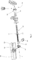
- Nachfolgend wird die Erfindung anhand von beispielhaften Zeichnungen näher erläutert. Hierbei zeigt
-
Fig. 1 eine perspektivische Ansicht einer Einstellvorrichtung zur Einstellung einer optisch relevanten Baueinheit eines Kraftfahrzeugscheinwerfers, -
Fig. 2 eine Explosionsansicht der Einstellvorrichtung ausFig. 1 , -
Fig. 3 einen seitlichen Querschnitt durch die Einstellvorrichtung ausFig. 1 , -
Fig. 3a einen Querschnitt entlang einer Schnittebene B-B ausFig. 3 , -
Fig. 4 eine perspektivische Ansicht eines weiteren Beispiels einer Einstellvorrichtung mit einem Elektromotor als Antriebsvorrichtung, und -
Fig. 5 eine weitere perspektivische Ansicht des Beispiels ausFig. 4 . - Grundsätzlich kann es sich bei der optisch relevanten Baueinheit aber um ein Einzelteil eines Kraftfahrzeugscheinwerfers oder einer Leuchteinheit, etwa um einen Reflektor, eine Linse, eine Lichtquelle, eine Blendenanordnung etc. handeln, oder die optisch relevante Baueinheit umfasst ein oder mehrere solcher Bauteile oder ein oder mehrere Leuchteinheiten auf einem gemeinsamen Träger, der verschwenkbar ist.
- Im Folgenden wird der Einfachheit halber von einem Lichtmodul als optisch relevante Baueinheit ausgegangen.
- Wie insbesondere den
Figuren 1 bis 3 entnommen werden kann, umfasst die Einstellvorrichtung 100 ein Stellelement 300, das vorzugsweise als Stellstange ausgebildet ist, wobei das Stellelement 300 mit einem Verbindungsteil 600 verbunden ist, das als mechanische Verbindung zwischen dem Kopplungselement 360 des Stellelements 300 und der einzustellenden, optisch relevanten Baueinheit fungiert, wobei das Verbindungsteil 600 als von der optischen Baueinheit, welche nicht in den Figuren dargestellt ist, getrenntes Bauteil ausgebildet ist. - Das Verbindungsteil 600 weist in der in den Figuren dargestellten Ausführungsform einen Gelenksabschnitt auf, mit welchem das Stellelement 300 mit seinem als Kugelkopf ausgebildeten Kopplungselement 360 gelenkig verbunden ist.
- Die Antriebsvorrichtung 150, welche vorzugsweise an einem Scheinwerfergehäuse gelagert sein kann, ist beispielsweise manuell betätigbar und umfasst in dem in den Figuren gezeigten Ausführungsbeispiels eine Einstellschraube 700, deren Drehbewegung in bekannter Weise in eine Drehbewegung eines Übertragungselements 200 umgesetzt wird, das um eine Verschubachse X drehbar gelagert ist.
- Das Übertragungselement 200 weist zudem eine Öffnung 210 auf, in welche das Stellelement 300 teilweise eingeschoben ist. Durch die Querschnittsausgestaltung der Öffnung 210 des Übertragungselements 200 und des entsprechenden dazu korrespondierenden Abschnitts des Stellelements 300 kann das Stellelement 300 um eine Verschubachse X gedreht werden, d.h. dass bei einer Drehbewegung des Übertragungselements 200 das Stellelement 300 ebenfalls mit verdreht wird.
- Hierzu weist das Übertragungselement elastische Zungen 250 auf, die am Umfang der im Wesentlichen kreisförmigen Öffnung 210 angeordnet sind und sich entlang der Verschubachse X erstrecken, wobei die elastischen Zungen 250 Vorsprünge 260 aufweisen, die dazu eingerichtet sin, in auf dem Stellelement angeordnete, korrespondierende Vertiefungen 320 einzugreifen.
- Die Vorsprünge 260 sind können beispielsweise in Form von zur Verschubachse X achsenparallelen Zapfen und die dazu korrespondierenden Vertiefungen 320 in Form von achsenparallelen Rillen ausgeführt sein, wie in
Fig. 1 und2 angedeutet ist. - Einen Querschnitt der Schnittebene B-B aus
Fig. 3 der oben beschriebenen mechanischen Verbindung zwischen dem Stellelement und dem Übertragungselement ist inFig. 3a gezeigt. - Im zusammengebauten Zustand ist das Stellelement 300 in der Öffnung 210 des Übertragungselements 200 aufgenommen, wobei die Vorsprünge 260 in die Vertiefungen 320 dergestalt eingreifen, dass eine Verschiebung des Stellelements 300 in Bezug auf das Übertragungselement 200 entlang der Verschubachse X möglich ist.
- Eine Drehbewegung des Übertragungselements 200 um die Verschubachse X wird über die Vorsprünge 260 mittels der Vertiefungen 320 auf das Stellelement 300 übertragen, sofern das dabei übertragene Drehmoment ein maximales Begrenzungsdrehmoment nicht überschreitet.
- Ist beispielsweise der Maximalhub des Stellelements 300 in Bezug auf das Übertragungselement 200 erreicht, so kann eine mechanische Überlastung ihrer Verbindung verhindert werden, indem sich ab einem definierten Drehmoment die elastischen Zungen 250 derart verformen, dass die Vorsprünge 260 aus den korrespondierenden Vertiefungen 320 gleiten und ein "Durchdrehen" des Übertragungselements 200 in Bezug auf das Stellelement 300 ermöglichen.
- Weiters weist das Stellelement 300 einen Gewindeabschnitt 350 auf, mittels welchem das Stellelement 300 mit einem ein zum Gewindeabschnitt 350 des Stellelements 300 korrespondierenden Gegengewinde 410 aufweisendes Führungsteil 400 um seine Längsachse bzw. der Verschubachse X drehbar gelagert ist, wobei das Führungsteil 400 in Bezug auf die Antriebsvorrichtung 150 feststehend in einer Führungsaufnahme 500 angeordnet ist.
- Das Führungsteil 400 ist in dem in den Figuren gezeigten Ausführungsbeispiel lösbar bzw. austauschbar an der Führungsaufnahme 500 befestigt.
- Die Führungsaufnahme 500 ist beispielsweise mit einem Scheinwerfergehäuse fest verbunden ist und beispielsweise mittels Schrauben angeschraubt.
- Zudem weist die Führungsaufnahme 500 einen ersten und einen zweiten Anschlag 510, 520 auf, die in Verbindung mit zwei an dem Stellelement 300 angeordneten, radial zur Verschubachse X vorragenden Vorsprüngen 310 die Schubbewegung des Stellelements 300 entlang der Verschubachse X begrenzen.
-
Fig. 4 zeigt eine weitere beispielhafte Ausführungsform der Einstellvorrichtung mit einem Elektromotor als Antriebsvorrichtung 150 in einer perspektivischen Ansicht, wobei die übrigen Merkmale im Wesentlichen identisch sind zu den Beispielen ausFig. 1 bis 3a . -
Fig. 5 die Ausführungsform der Einstellvorrichtung ausFig. 4 in einer weiteren perspektivischen Ansicht. -
- Einstellvorrichtung
- 100
- Antriebsvorrichtung
- 150
- Verschubachse
- X
- Übertragungselement
- 200
- Öffnung
- 210
- Elastische Zungen
- 250
- Vorsprünge
- 260
- Stellelement
- 300
- Vorsprung
- 310
- Vertiefungen
- 320
- Gewindeabschnitt
- 350
- Kopplungselement
- 360
- Führungsteil
- 400
- Gegengewinde
- 410
- Führungsaufnahme
- 500
- Erster und zweiter Anschlag
- 510, 520
- Verbindungsteil
- 600
- Einstellschraube
- 700
Claims (11)
- Einstellvorrichtung (100) zur Einstellung einer optisch relevanten Baueinheit eines Kraftfahrzeugscheinwerfers, welche Einstellvorrichtung Folgendes umfasst:- eine Antriebsvorrichtung (150) mit einem um eine Verschubachse (X) drehbar gelagerten Übertragungselement (200),- ein mit dem Übertragungselement (200) mittels einer Verbindung in mechanischem Eingriff stehendes Stellelement (300), wobei das Stellelement (300) einen Gewindeabschnitt (350) aufweist und ferner dazu eingerichtet ist, an der optisch relevanten Baueinheit mittels einem Kopplungselement (360) anzugreifen, und- eine Führungsaufnahme (500) sowie ein in der Führungsaufnahme (500) angeordnetes Führungsteil (400) mit einem den Gewindeabschnitt (350) korrespondierenden Gegengewinde (410), wobei das Stellelement (300) mittels des auf den Gewindeabschnitt (350) angeordneten Führungsteils (400), welches in Kombination mit dem Gewindeabschnitt (350) dazu eingerichtet ist, eine Drehbewegung des Übertragungselements (200) in eine Schiebebewegung entlang der Verschubachse (X) zu wandeln, in der Führungsaufnahme (500) dreh- und verschiebbar gelagert ist,dadurch gekennzeichnet, dass
das Stellelement (300) zumindest einen radial zur Verschubachse (X) vorragenden Vorsprung (310) und die Führungsaufnahme (500) einen ersten und einen zweiten dazu korrespondierenden Anschlag (510, 520) aufweist, wobei der Vorsprung (310) sowie der erste und zweite Anschlag (510, 520) dazu eingerichtet sind, den Hub des Stellelements (300) entlang der Verschubachse (X) zu begrenzen. - Einstellvorrichtung nach Anspruch 1, dadurch gekennzeichnet, dass das Stellelement (300) zumindest teilweise in einer im Wesentlichen kreisförmigen, konzentrisch zur Verschubachse angeordneten Öffnung (210) des Übertragungselements (200) aufgenommen ist, wobei das Übertragungselement (200) als Überdrehschutz elastische Zungen (250) aufweist, die am Umfang der im Wesentlichen kreisförmigen Öffnung (210) angeordnet sind und sich entlang der Verschubachse (X) erstrecken, wobei die elastischen Zungen (250) Vorsprünge (260) aufweisen, die dazu eingerichtet sind, in auf dem Stellelement angeordnete, korrespondierende Vertiefungen (320) einzugreifen.
- Einstellvorrichtung nach Anspruch 1 oder 2, dadurch gekennzeichnet, dass die Vorsprünge (260) in Form von achsenparallelen Zapfen und die dazu korrespondierenden Vertiefungen (320) als achsenparallele Rillen ausgeführt sind.
- Einstellvorrichtung nach Anspruch 1 bis 3, dadurch gekennzeichnet, dass das Führungsteil (400) lösbar in der Führungsaufnahme (500) angeordnet ist.
- Einstellvorrichtung nach einem der Ansprüche 1 bis 4, dadurch gekennzeichnet, dass die Antriebsvorrichtung (150) als mechanischer Motor, vorzugsweise mit einem Winkelgetriebe, ausgebildet ist.
- Einstellvorrichtung nach einem der Ansprüche 1 bis 4, dadurch gekennzeichnet, dass die Antriebsvorrichtung (150) als Elektromotor ausgebildet ist.
- Einstellvorrichtung nach einem der Ansprüche 1 bis 6, dadurch gekennzeichnet, dass das Kopplungselement (360) durch einen konzentrisch zur Verschubachse (X) angeordneten Kugelkopf gebildet ist.
- Einstellvorrichtung nach einem der Ansprüche 1 bis 7, dadurch gekennzeichnet, dass das Kopplungselement (360) als von dem Stellelement (300) lösbare Schraube ausgebildet ist.
- Kraftfahrzeugscheinwerfer mit einem Gehäuse und zumindest einer optisch relevanten Baueinheit sowie mit zumindest einer Einstellvorrichtung gemäß einem der Ansprüche 1 bis 8.
- Kraftfahrzeugscheinwerfer nach Anspruch 9, dadurch gekennzeichnet, dass das Führungsteil (400) in Bezug auf das Gehäuse des Kraftfahrzeugscheinwerfers feststehend angeordnet ist.
- Kraftfahrzeugscheinwerfer nach Anspruch 9 oder 10, dadurch gekennzeichnet, dass die Führungsaufnahme (500) mit dem Gehäuse des Kraftfahrzeugscheinwerfers fest verbunden ist.
Priority Applications (3)
| Application Number | Priority Date | Filing Date | Title |
|---|---|---|---|
| EP18191011.8A EP3616993B1 (de) | 2018-08-27 | 2018-08-27 | Kraftfahrzeugscheinwerfer mit einer einstellvorrichtung |
| KR1020190096893A KR20200024085A (ko) | 2018-08-27 | 2019-08-08 | 자동차 헤드램프용 설정 장치 |
| CN201910795670.XA CN110864264B (zh) | 2018-08-27 | 2019-08-27 | 用于机动车前照灯的调整装置 |
Applications Claiming Priority (1)
| Application Number | Priority Date | Filing Date | Title |
|---|---|---|---|
| EP18191011.8A EP3616993B1 (de) | 2018-08-27 | 2018-08-27 | Kraftfahrzeugscheinwerfer mit einer einstellvorrichtung |
Publications (2)
| Publication Number | Publication Date |
|---|---|
| EP3616993A1 true EP3616993A1 (de) | 2020-03-04 |
| EP3616993B1 EP3616993B1 (de) | 2023-05-24 |
Family
ID=63490212
Family Applications (1)
| Application Number | Title | Priority Date | Filing Date |
|---|---|---|---|
| EP18191011.8A Active EP3616993B1 (de) | 2018-08-27 | 2018-08-27 | Kraftfahrzeugscheinwerfer mit einer einstellvorrichtung |
Country Status (3)
| Country | Link |
|---|---|
| EP (1) | EP3616993B1 (de) |
| KR (1) | KR20200024085A (de) |
| CN (1) | CN110864264B (de) |
Cited By (4)
| Publication number | Priority date | Publication date | Assignee | Title |
|---|---|---|---|---|
| CN113357610A (zh) * | 2020-03-06 | 2021-09-07 | Zkw集团有限责任公司 | 用于调整机动车大灯的光学地相关的结构单元的调整装置 |
| WO2022078607A1 (en) * | 2020-10-15 | 2022-04-21 | HELLA GmbH & Co. KGaA | Thermal-expansion compensator for holding a light module in a housing of a headlamp of a motor vehicle |
| JP2023037233A (ja) * | 2021-09-03 | 2023-03-15 | Jfeスチール株式会社 | 中空材の清掃治具およびその清掃治具を用いた中空材の清掃方法 |
| CN116215361A (zh) * | 2021-12-03 | 2023-06-06 | Zkw集团有限责任公司 | 用于同时调整机动车的照明设备的光模块的调整装置 |
Families Citing this family (4)
| Publication number | Priority date | Publication date | Assignee | Title |
|---|---|---|---|---|
| CN111649298B (zh) * | 2020-05-04 | 2022-08-16 | 广州星耀汽车科技发展有限公司 | 一种汽车前照灯调光功能的导向结构 |
| EP3915835A1 (de) * | 2020-05-27 | 2021-12-01 | ZKW Group GmbH | Einstellungsvorrichtung |
| EP4163153B1 (de) * | 2021-10-07 | 2025-06-04 | ZKW Group GmbH | Einstellsystem zum einstellen eines lichtmoduls eines fahrzeugscheinwerfers |
| EP4197858B1 (de) * | 2021-12-16 | 2024-07-03 | ZKW Group GmbH | Stossabsorbierendes fahrzeugscheinwerfersystem |
Citations (6)
| Publication number | Priority date | Publication date | Assignee | Title |
|---|---|---|---|---|
| DE19619586A1 (de) * | 1995-05-29 | 1996-12-05 | Valeo Vision | Einstellvorrichtung für einen beweglichen Teil eines Scheinwerfers für Kraftfahrzeuge |
| DE10332976A1 (de) * | 2003-07-21 | 2005-04-21 | Hella Kgaa Hueck & Co | Scheinwerfer für Fahrzeuge |
| DE102011017538A1 (de) * | 2011-04-26 | 2012-10-31 | Automotive Lighting Reutlingen Gmbh | Kompakte vertikale Verstelleinheit für Scheinwerfer mit überlagerter horizontaler Grundeinstellung |
| WO2013025176A1 (en) * | 2011-08-12 | 2013-02-21 | Hella Saturnus Slovenija, Proizvodnja Svetlobne Opreme Za Motorna In Druga Vozila, D.O.O. | Motor vehicle headlight regulating assembly |
| EP2786897A1 (de) * | 2013-04-04 | 2014-10-08 | Zizala Lichtsysteme GmbH | Verstelleinrichtung für einen Fahrzeugscheinwerfer |
| FR3022984A1 (fr) * | 2014-06-27 | 2016-01-01 | Valeo Iluminacion Sa | Dispositif de reglage de l'inclinaison d'un reflecteur |
Family Cites Families (1)
| Publication number | Priority date | Publication date | Assignee | Title |
|---|---|---|---|---|
| CN107082042A (zh) * | 2017-06-22 | 2017-08-22 | 河南天海电器有限公司 | 汽车前照灯远近光切换用遮光机构及其球头模块 |
-
2018
- 2018-08-27 EP EP18191011.8A patent/EP3616993B1/de active Active
-
2019
- 2019-08-08 KR KR1020190096893A patent/KR20200024085A/ko not_active Ceased
- 2019-08-27 CN CN201910795670.XA patent/CN110864264B/zh active Active
Patent Citations (6)
| Publication number | Priority date | Publication date | Assignee | Title |
|---|---|---|---|---|
| DE19619586A1 (de) * | 1995-05-29 | 1996-12-05 | Valeo Vision | Einstellvorrichtung für einen beweglichen Teil eines Scheinwerfers für Kraftfahrzeuge |
| DE10332976A1 (de) * | 2003-07-21 | 2005-04-21 | Hella Kgaa Hueck & Co | Scheinwerfer für Fahrzeuge |
| DE102011017538A1 (de) * | 2011-04-26 | 2012-10-31 | Automotive Lighting Reutlingen Gmbh | Kompakte vertikale Verstelleinheit für Scheinwerfer mit überlagerter horizontaler Grundeinstellung |
| WO2013025176A1 (en) * | 2011-08-12 | 2013-02-21 | Hella Saturnus Slovenija, Proizvodnja Svetlobne Opreme Za Motorna In Druga Vozila, D.O.O. | Motor vehicle headlight regulating assembly |
| EP2786897A1 (de) * | 2013-04-04 | 2014-10-08 | Zizala Lichtsysteme GmbH | Verstelleinrichtung für einen Fahrzeugscheinwerfer |
| FR3022984A1 (fr) * | 2014-06-27 | 2016-01-01 | Valeo Iluminacion Sa | Dispositif de reglage de l'inclinaison d'un reflecteur |
Cited By (8)
| Publication number | Priority date | Publication date | Assignee | Title |
|---|---|---|---|---|
| CN113357610A (zh) * | 2020-03-06 | 2021-09-07 | Zkw集团有限责任公司 | 用于调整机动车大灯的光学地相关的结构单元的调整装置 |
| EP3875315A1 (de) * | 2020-03-06 | 2021-09-08 | ZKW Group GmbH | Einstellvorrichtung zur einstellung einer optisch relevanten baueinheit eines kraftfahrzeugscheinwerfers |
| WO2022078607A1 (en) * | 2020-10-15 | 2022-04-21 | HELLA GmbH & Co. KGaA | Thermal-expansion compensator for holding a light module in a housing of a headlamp of a motor vehicle |
| JP2023037233A (ja) * | 2021-09-03 | 2023-03-15 | Jfeスチール株式会社 | 中空材の清掃治具およびその清掃治具を用いた中空材の清掃方法 |
| CN116215361A (zh) * | 2021-12-03 | 2023-06-06 | Zkw集团有限责任公司 | 用于同时调整机动车的照明设备的光模块的调整装置 |
| EP4190635A1 (de) * | 2021-12-03 | 2023-06-07 | ZKW Group GmbH | Verstelleinrichtung zur gleichzeitigen verstellung von lichtmodulen einer beleuchtungsvorrichtung für ein kraftfahrzeug |
| JP2023083247A (ja) * | 2021-12-03 | 2023-06-15 | ツェットカーヴェー グループ ゲーエムベーハー | 自動車用の照射装置のライトモジュールを同時に調節するための調節装置 |
| US11835192B2 (en) | 2021-12-03 | 2023-12-05 | Zkw Group Gmbh | Displacement system for simultaneous displacement of light modules of lighting apparatus for motor vehicle |
Also Published As
| Publication number | Publication date |
|---|---|
| CN110864264A (zh) | 2020-03-06 |
| CN110864264B (zh) | 2023-01-06 |
| KR20200024085A (ko) | 2020-03-06 |
| EP3616993B1 (de) | 2023-05-24 |
Similar Documents
| Publication | Publication Date | Title |
|---|---|---|
| EP3616993B1 (de) | Kraftfahrzeugscheinwerfer mit einer einstellvorrichtung | |
| AT514402B1 (de) | Fahrzeugscheinwerfer | |
| EP2918447B1 (de) | Einstellvorrichtung für einen Fahrzeugscheinwerfer | |
| EP2762358B1 (de) | Einstellsystem für einen Fahrzeug-Scheinwerfer | |
| EP2786897B1 (de) | Fahrzeugscheinwerfer mit einer Verstelleinrichtung | |
| EP3616992B1 (de) | Einstellvorrichtung für einen kraftfahrzeugscheinwerfer | |
| DE102014200237B4 (de) | Scheinwerfer eines Kraftfahrzeugs | |
| EP3898326B1 (de) | Einstellvorrichtung für einen kraftfahrzeugscheinwerfer | |
| EP3566902B1 (de) | Einstellvorrichtung für einen kraftfahrzeugscheinwerfer | |
| EP2697562B1 (de) | Vorrichtung zum verstellen eines im gehäuse eines scheinwerfers oder optischen geräts angeordneten optischen tubus | |
| WO2019137736A1 (de) | Einstellsystem zum verschwenken zumindest eines optisch relevanten bauteils eines fahrzeugscheinwerfers um eine erste und eine zweite achse | |
| EP3927580B1 (de) | Beleuchtungsvorrichtung für einen kraftfahrzeugscheinwerfer | |
| DE60034085T2 (de) | Kraftfahrzeug-Scheinwerfer zur Erzeugung von zwei verschiedenen Lichtstrahlen mit einer einzigen Lichtquelle | |
| AT513203B1 (de) | Verstelleinrichtung für einen Kraftfahrzeugscheinwerfer sowie Kraftfahrzeugscheinwerfer | |
| DE3128642A1 (de) | Zoomobjektivaufbau | |
| EP4094049B1 (de) | Einstellvorrichtung zum verschwenken zumindest eines relevanten bauteils für einen kraftfahrzeugscheinwerfer | |
| DE102013213254A1 (de) | Betätigungseinheit für ein optisches element mit zweidimensionalem stellantrieb | |
| EP3807688B1 (de) | Strahlaufweiter und verfahren zum betreiben eines strahlaufweiters | |
| DE102013106562A1 (de) | Verstelleinrichtung für einen Kraftfahrzeugscheinwerfer | |
| EP3875315A1 (de) | Einstellvorrichtung zur einstellung einer optisch relevanten baueinheit eines kraftfahrzeugscheinwerfers | |
| AT506090B1 (de) | Verstellbare lampenhalterung | |
| DE202020005947U1 (de) | Einstellvorrichtung zur Einstellung einer optisch relevanten Baueinheit eines Kraftfahrzeugscheinwerfers | |
| EP2436557A2 (de) | Verstellvorrichtung zum Verstellen eines optisch relevanten Bauteils eines Fahrzeugscheinwerfers | |
| DE102012217838A1 (de) | Justiervorrichtung für ein optisches Element eines Teleskops | |
| DE7535767U (de) | Beleuchtungsscheinwerfer |
Legal Events
| Date | Code | Title | Description |
|---|---|---|---|
| PUAI | Public reference made under article 153(3) epc to a published international application that has entered the european phase |
Free format text: ORIGINAL CODE: 0009012 |
|
| STAA | Information on the status of an ep patent application or granted ep patent |
Free format text: STATUS: THE APPLICATION HAS BEEN PUBLISHED |
|
| AK | Designated contracting states |
Kind code of ref document: A1 Designated state(s): AL AT BE BG CH CY CZ DE DK EE ES FI FR GB GR HR HU IE IS IT LI LT LU LV MC MK MT NL NO PL PT RO RS SE SI SK SM TR |
|
| AX | Request for extension of the european patent |
Extension state: BA ME |
|
| STAA | Information on the status of an ep patent application or granted ep patent |
Free format text: STATUS: REQUEST FOR EXAMINATION WAS MADE |
|
| 17P | Request for examination filed |
Effective date: 20200827 |
|
| RBV | Designated contracting states (corrected) |
Designated state(s): AL AT BE BG CH CY CZ DE DK EE ES FI FR GB GR HR HU IE IS IT LI LT LU LV MC MK MT NL NO PL PT RO RS SE SI SK SM TR |
|
| GRAP | Despatch of communication of intention to grant a patent |
Free format text: ORIGINAL CODE: EPIDOSNIGR1 |
|
| STAA | Information on the status of an ep patent application or granted ep patent |
Free format text: STATUS: GRANT OF PATENT IS INTENDED |
|
| INTG | Intention to grant announced |
Effective date: 20221223 |
|
| GRAS | Grant fee paid |
Free format text: ORIGINAL CODE: EPIDOSNIGR3 |
|
| GRAA | (expected) grant |
Free format text: ORIGINAL CODE: 0009210 |
|
| STAA | Information on the status of an ep patent application or granted ep patent |
Free format text: STATUS: THE PATENT HAS BEEN GRANTED |
|
| AK | Designated contracting states |
Kind code of ref document: B1 Designated state(s): AL AT BE BG CH CY CZ DE DK EE ES FI FR GB GR HR HU IE IS IT LI LT LU LV MC MK MT NL NO PL PT RO RS SE SI SK SM TR |
|
| REG | Reference to a national code |
Ref country code: GB Ref legal event code: FG4D Free format text: NOT ENGLISH |
|
| REG | Reference to a national code |
Ref country code: CH Ref legal event code: EP |
|
| REG | Reference to a national code |
Ref country code: DE Ref legal event code: R096 Ref document number: 502018012173 Country of ref document: DE |
|
| REG | Reference to a national code |
Ref country code: AT Ref legal event code: REF Ref document number: 1569319 Country of ref document: AT Kind code of ref document: T Effective date: 20230615 |
|
| REG | Reference to a national code |
Ref country code: IE Ref legal event code: FG4D Free format text: LANGUAGE OF EP DOCUMENT: GERMAN |
|
| P01 | Opt-out of the competence of the unified patent court (upc) registered |
Effective date: 20230528 |
|
| REG | Reference to a national code |
Ref country code: LT Ref legal event code: MG9D |
|
| REG | Reference to a national code |
Ref country code: NL Ref legal event code: MP Effective date: 20230524 |
|
| PG25 | Lapsed in a contracting state [announced via postgrant information from national office to epo] |
Ref country code: SE Free format text: LAPSE BECAUSE OF FAILURE TO SUBMIT A TRANSLATION OF THE DESCRIPTION OR TO PAY THE FEE WITHIN THE PRESCRIBED TIME-LIMIT Effective date: 20230524 Ref country code: PT Free format text: LAPSE BECAUSE OF FAILURE TO SUBMIT A TRANSLATION OF THE DESCRIPTION OR TO PAY THE FEE WITHIN THE PRESCRIBED TIME-LIMIT Effective date: 20230925 Ref country code: NO Free format text: LAPSE BECAUSE OF FAILURE TO SUBMIT A TRANSLATION OF THE DESCRIPTION OR TO PAY THE FEE WITHIN THE PRESCRIBED TIME-LIMIT Effective date: 20230824 Ref country code: NL Free format text: LAPSE BECAUSE OF FAILURE TO SUBMIT A TRANSLATION OF THE DESCRIPTION OR TO PAY THE FEE WITHIN THE PRESCRIBED TIME-LIMIT Effective date: 20230524 Ref country code: ES Free format text: LAPSE BECAUSE OF FAILURE TO SUBMIT A TRANSLATION OF THE DESCRIPTION OR TO PAY THE FEE WITHIN THE PRESCRIBED TIME-LIMIT Effective date: 20230524 |
|
| PG25 | Lapsed in a contracting state [announced via postgrant information from national office to epo] |
Ref country code: RS Free format text: LAPSE BECAUSE OF FAILURE TO SUBMIT A TRANSLATION OF THE DESCRIPTION OR TO PAY THE FEE WITHIN THE PRESCRIBED TIME-LIMIT Effective date: 20230524 Ref country code: PL Free format text: LAPSE BECAUSE OF FAILURE TO SUBMIT A TRANSLATION OF THE DESCRIPTION OR TO PAY THE FEE WITHIN THE PRESCRIBED TIME-LIMIT Effective date: 20230524 Ref country code: LV Free format text: LAPSE BECAUSE OF FAILURE TO SUBMIT A TRANSLATION OF THE DESCRIPTION OR TO PAY THE FEE WITHIN THE PRESCRIBED TIME-LIMIT Effective date: 20230524 Ref country code: LT Free format text: LAPSE BECAUSE OF FAILURE TO SUBMIT A TRANSLATION OF THE DESCRIPTION OR TO PAY THE FEE WITHIN THE PRESCRIBED TIME-LIMIT Effective date: 20230524 Ref country code: IS Free format text: LAPSE BECAUSE OF FAILURE TO SUBMIT A TRANSLATION OF THE DESCRIPTION OR TO PAY THE FEE WITHIN THE PRESCRIBED TIME-LIMIT Effective date: 20230924 Ref country code: HR Free format text: LAPSE BECAUSE OF FAILURE TO SUBMIT A TRANSLATION OF THE DESCRIPTION OR TO PAY THE FEE WITHIN THE PRESCRIBED TIME-LIMIT Effective date: 20230524 Ref country code: GR Free format text: LAPSE BECAUSE OF FAILURE TO SUBMIT A TRANSLATION OF THE DESCRIPTION OR TO PAY THE FEE WITHIN THE PRESCRIBED TIME-LIMIT Effective date: 20230825 |
|
| PG25 | Lapsed in a contracting state [announced via postgrant information from national office to epo] |
Ref country code: FI Free format text: LAPSE BECAUSE OF FAILURE TO SUBMIT A TRANSLATION OF THE DESCRIPTION OR TO PAY THE FEE WITHIN THE PRESCRIBED TIME-LIMIT Effective date: 20230524 |
|
| PG25 | Lapsed in a contracting state [announced via postgrant information from national office to epo] |
Ref country code: SK Free format text: LAPSE BECAUSE OF FAILURE TO SUBMIT A TRANSLATION OF THE DESCRIPTION OR TO PAY THE FEE WITHIN THE PRESCRIBED TIME-LIMIT Effective date: 20230524 |
|
| PG25 | Lapsed in a contracting state [announced via postgrant information from national office to epo] |
Ref country code: SM Free format text: LAPSE BECAUSE OF FAILURE TO SUBMIT A TRANSLATION OF THE DESCRIPTION OR TO PAY THE FEE WITHIN THE PRESCRIBED TIME-LIMIT Effective date: 20230524 Ref country code: SK Free format text: LAPSE BECAUSE OF FAILURE TO SUBMIT A TRANSLATION OF THE DESCRIPTION OR TO PAY THE FEE WITHIN THE PRESCRIBED TIME-LIMIT Effective date: 20230524 Ref country code: RO Free format text: LAPSE BECAUSE OF FAILURE TO SUBMIT A TRANSLATION OF THE DESCRIPTION OR TO PAY THE FEE WITHIN THE PRESCRIBED TIME-LIMIT Effective date: 20230524 Ref country code: EE Free format text: LAPSE BECAUSE OF FAILURE TO SUBMIT A TRANSLATION OF THE DESCRIPTION OR TO PAY THE FEE WITHIN THE PRESCRIBED TIME-LIMIT Effective date: 20230524 Ref country code: DK Free format text: LAPSE BECAUSE OF FAILURE TO SUBMIT A TRANSLATION OF THE DESCRIPTION OR TO PAY THE FEE WITHIN THE PRESCRIBED TIME-LIMIT Effective date: 20230524 Ref country code: CZ Free format text: LAPSE BECAUSE OF FAILURE TO SUBMIT A TRANSLATION OF THE DESCRIPTION OR TO PAY THE FEE WITHIN THE PRESCRIBED TIME-LIMIT Effective date: 20230524 |
|
| REG | Reference to a national code |
Ref country code: DE Ref legal event code: R097 Ref document number: 502018012173 Country of ref document: DE |
|
| PG25 | Lapsed in a contracting state [announced via postgrant information from national office to epo] |
Ref country code: MC Free format text: LAPSE BECAUSE OF FAILURE TO SUBMIT A TRANSLATION OF THE DESCRIPTION OR TO PAY THE FEE WITHIN THE PRESCRIBED TIME-LIMIT Effective date: 20230524 |
|
| REG | Reference to a national code |
Ref country code: CH Ref legal event code: PL |
|
| PG25 | Lapsed in a contracting state [announced via postgrant information from national office to epo] |
Ref country code: MC Free format text: LAPSE BECAUSE OF FAILURE TO SUBMIT A TRANSLATION OF THE DESCRIPTION OR TO PAY THE FEE WITHIN THE PRESCRIBED TIME-LIMIT Effective date: 20230524 |
|
| PLBE | No opposition filed within time limit |
Free format text: ORIGINAL CODE: 0009261 |
|
| STAA | Information on the status of an ep patent application or granted ep patent |
Free format text: STATUS: NO OPPOSITION FILED WITHIN TIME LIMIT |
|
| PG25 | Lapsed in a contracting state [announced via postgrant information from national office to epo] |
Ref country code: LU Free format text: LAPSE BECAUSE OF NON-PAYMENT OF DUE FEES Effective date: 20230827 |
|
| GBPC | Gb: european patent ceased through non-payment of renewal fee |
Effective date: 20230827 |
|
| PG25 | Lapsed in a contracting state [announced via postgrant information from national office to epo] |
Ref country code: LU Free format text: LAPSE BECAUSE OF NON-PAYMENT OF DUE FEES Effective date: 20230827 Ref country code: CH Free format text: LAPSE BECAUSE OF NON-PAYMENT OF DUE FEES Effective date: 20230831 |
|
| 26N | No opposition filed |
Effective date: 20240227 |
|
| PG25 | Lapsed in a contracting state [announced via postgrant information from national office to epo] |
Ref country code: SI Free format text: LAPSE BECAUSE OF FAILURE TO SUBMIT A TRANSLATION OF THE DESCRIPTION OR TO PAY THE FEE WITHIN THE PRESCRIBED TIME-LIMIT Effective date: 20230524 |
|
| REG | Reference to a national code |
Ref country code: BE Ref legal event code: MM Effective date: 20230831 |
|
| REG | Reference to a national code |
Ref country code: IE Ref legal event code: MM4A |
|
| PG25 | Lapsed in a contracting state [announced via postgrant information from national office to epo] |
Ref country code: SI Free format text: LAPSE BECAUSE OF FAILURE TO SUBMIT A TRANSLATION OF THE DESCRIPTION OR TO PAY THE FEE WITHIN THE PRESCRIBED TIME-LIMIT Effective date: 20230524 Ref country code: IT Free format text: LAPSE BECAUSE OF FAILURE TO SUBMIT A TRANSLATION OF THE DESCRIPTION OR TO PAY THE FEE WITHIN THE PRESCRIBED TIME-LIMIT Effective date: 20230524 |
|
| PG25 | Lapsed in a contracting state [announced via postgrant information from national office to epo] |
Ref country code: IE Free format text: LAPSE BECAUSE OF NON-PAYMENT OF DUE FEES Effective date: 20230827 |
|
| PG25 | Lapsed in a contracting state [announced via postgrant information from national office to epo] |
Ref country code: GB Free format text: LAPSE BECAUSE OF NON-PAYMENT OF DUE FEES Effective date: 20230827 |
|
| PG25 | Lapsed in a contracting state [announced via postgrant information from national office to epo] |
Ref country code: IE Free format text: LAPSE BECAUSE OF NON-PAYMENT OF DUE FEES Effective date: 20230827 Ref country code: GB Free format text: LAPSE BECAUSE OF NON-PAYMENT OF DUE FEES Effective date: 20230827 |
|
| PG25 | Lapsed in a contracting state [announced via postgrant information from national office to epo] |
Ref country code: BE Free format text: LAPSE BECAUSE OF NON-PAYMENT OF DUE FEES Effective date: 20230831 |
|
| REG | Reference to a national code |
Ref country code: AT Ref legal event code: MM01 Ref document number: 1569319 Country of ref document: AT Kind code of ref document: T Effective date: 20230827 |
|
| PG25 | Lapsed in a contracting state [announced via postgrant information from national office to epo] |
Ref country code: AT Free format text: LAPSE BECAUSE OF NON-PAYMENT OF DUE FEES Effective date: 20230827 |
|
| PG25 | Lapsed in a contracting state [announced via postgrant information from national office to epo] |
Ref country code: AT Free format text: LAPSE BECAUSE OF NON-PAYMENT OF DUE FEES Effective date: 20230827 |
|
| PG25 | Lapsed in a contracting state [announced via postgrant information from national office to epo] |
Ref country code: BG Free format text: LAPSE BECAUSE OF FAILURE TO SUBMIT A TRANSLATION OF THE DESCRIPTION OR TO PAY THE FEE WITHIN THE PRESCRIBED TIME-LIMIT Effective date: 20230524 |
|
| PG25 | Lapsed in a contracting state [announced via postgrant information from national office to epo] |
Ref country code: BG Free format text: LAPSE BECAUSE OF FAILURE TO SUBMIT A TRANSLATION OF THE DESCRIPTION OR TO PAY THE FEE WITHIN THE PRESCRIBED TIME-LIMIT Effective date: 20230524 |
|
| PG25 | Lapsed in a contracting state [announced via postgrant information from national office to epo] |
Ref country code: CY Free format text: LAPSE BECAUSE OF FAILURE TO SUBMIT A TRANSLATION OF THE DESCRIPTION OR TO PAY THE FEE WITHIN THE PRESCRIBED TIME-LIMIT; INVALID AB INITIO Effective date: 20180827 |
|
| PG25 | Lapsed in a contracting state [announced via postgrant information from national office to epo] |
Ref country code: HU Free format text: LAPSE BECAUSE OF FAILURE TO SUBMIT A TRANSLATION OF THE DESCRIPTION OR TO PAY THE FEE WITHIN THE PRESCRIBED TIME-LIMIT; INVALID AB INITIO Effective date: 20180827 |
|
| PGFP | Annual fee paid to national office [announced via postgrant information from national office to epo] |
Ref country code: DE Payment date: 20250819 Year of fee payment: 8 |
|
| PGFP | Annual fee paid to national office [announced via postgrant information from national office to epo] |
Ref country code: FR Payment date: 20250821 Year of fee payment: 8 |
|
| PG25 | Lapsed in a contracting state [announced via postgrant information from national office to epo] |
Ref country code: TR Free format text: LAPSE BECAUSE OF FAILURE TO SUBMIT A TRANSLATION OF THE DESCRIPTION OR TO PAY THE FEE WITHIN THE PRESCRIBED TIME-LIMIT Effective date: 20230524 |