EP3615929B1 - Verfahren zum bestimmen eines stickstoffgehaltes in festen oder flüssigen proben - Google Patents
Verfahren zum bestimmen eines stickstoffgehaltes in festen oder flüssigen proben Download PDFInfo
- Publication number
- EP3615929B1 EP3615929B1 EP18726906.3A EP18726906A EP3615929B1 EP 3615929 B1 EP3615929 B1 EP 3615929B1 EP 18726906 A EP18726906 A EP 18726906A EP 3615929 B1 EP3615929 B1 EP 3615929B1
- Authority
- EP
- European Patent Office
- Prior art keywords
- nitrogen
- gas
- hydrogen
- oxygen
- sample
- Prior art date
- Legal status (The legal status is an assumption and is not a legal conclusion. Google has not performed a legal analysis and makes no representation as to the accuracy of the status listed.)
- Active
Links
Images

Classifications
-
- G—PHYSICS
- G01—MEASURING; TESTING
- G01N—INVESTIGATING OR ANALYSING MATERIALS BY DETERMINING THEIR CHEMICAL OR PHYSICAL PROPERTIES
- G01N31/00—Investigating or analysing non-biological materials by the use of the chemical methods specified in the subgroup; Apparatus specially adapted for such methods
- G01N31/12—Investigating or analysing non-biological materials by the use of the chemical methods specified in the subgroup; Apparatus specially adapted for such methods using combustion
Definitions
- the invention relates to a method for determining a nitrogen content in solid or liquid samples, wherein a sample gas is generated by oxidizing the sample, a carrier gas is added to the sample gas and the oxygen and nitrogen oxide components in the sample gas are converted to water and nitrogen, with the remaining Nitrogen carrier gas mixture the proportion of nitrogen is detected.
- the protein content in foods such as wheat, milk or the like is usually determined via the nitrogen content of a sample.
- the nitrogen content is then converted to the protein content using a suitable factor.
- the nitrogen content is also of interest in substrates such as arable soil, in order to be able to determine the nutrient properties of the substrate using a sample.
- the DE 35 38 778 A1 discloses a method and apparatus for determining the level of nitrogen in a sample.
- the sample is burned in an oxygen-enriched, nitrogen-free, inert carrier gas.
- CD2 is used as carrier gas.
- a method for determining the carbon, water and nitrogen contents in an organic material is, for example, from U.S. 4,525,328C known.
- the organic material is burned and Added carrier gas.
- Very expensive helium is used as the carrier gas.
- This method is also known as the Dumas method.
- a sample is burned in an oxygen-containing carrier gas flow, interfering combustion products are removed by adsorption and the various oxidation products of the nitrogen are reduced to elementary nitrogen by chemical reduction, for example of copper or tungsten.
- the copper or tungsten needs to be heated to around 600-700°C.
- the oxygen and nitrogen oxide components are reduced, copper oxide or tungsten oxide is formed.
- This method has the major disadvantage that the reducing agent is consumed very quickly by oxidation and must be replaced while interrupting the analysis process. This leads to a large maintenance effort and to high costs of the process.
- the invention is based on the problem of enabling continuous conversion of nitrogen oxides into nitrogen and oxygen compounds.
- This problem is solved according to the invention in that hydrogen is added to the measurement gas to reduce the oxygen and nitrogen oxide components and that the reduction of the measurement gas takes place on a catalyst, with the parameters temperature, residence time, type of catalyst being selected such that nitrogen is formed and a further reduction to ammonia is avoided.
- the reduction of the oxygen and nitrogen oxide components in the measuring gas by means of hydrogen enables a continuous process flow. This leads to a significant simplification of the procedure, since no manual intervention in the analysis process is required.
- the oxygen in the sample gas is reduced by the added hydrogen to water and nitrogen oxides to nitrogen and water. This allows the nitrogen compounds to be converted into nitrogen and other combustion products.
- the method according to the invention is particularly cost-effective.
- the reduction of the measurement gas can be controlled reliably because the reduction of the measurement gas takes place at a catalytic converter.
- the products can be controlled via parameters such as temperature, residence time and the type of catalyst.
- the parameters are selected in such a way that as far as possible only nitrogen is produced; a further reduction to ammonia is to be avoided.
- Preference is given to using platinum or platinum metals, also as an alloy, as the catalyst.
- the use of helium as the carrier gas can easily be avoided if the carrier gas is hydrogen, so that more hydrogen is supplied to the measurement gas than is necessary for the reduction of the oxygen and nitrogen oxide components.
- the oxygen and nitrogen oxide components in the measurement gas are also converted in the event of excess hydrogen, which leads to a particularly reproducible process sequence.
- a disturbance in the determination due to various gas components can be easily avoided if gas components that do not contain nitrogen are separated off before the hydrogen is supplied.
- Such a separation can take place, for example, by absorptive or chromatographic means.
- the exact nitrogen content in the nitrogen carrier gas mixture can be determined particularly easily if the nitrogen in the nitrogen-hydrogen mixture is detected by determining the thermal conductivity.
- the concentration of the elements carbon, hydrogen and sulfur in the initial sample can be determined easily if the content of the oxidation products carbon dioxide, sulfur dioxide and water is detected after the oxidation of the sample and before the addition of hydrogen.
- a detection can easily be carried out by means of thermal conductivity detection or infrared detection.
- the method is particularly cost-effective if a gas split is carried out after the oxidation and the hydrogen is supplied exclusively to a designated fraction of the measurement gas.
- standard sample sizes can be examined without examining the entire measurement gas that is produced. For example, instead of the entire sample gas, only 10% of the sample gas is examined and the result is converted to the entire sample.
- the water produced during the reduction of the nitrogen components can be removed particularly cost-effectively if the water is separated off by cooling before the nitrogen content in the nitrogen carrier gas mixture is detected.
- FIG. 1 shows a method for determining a nitrogen content in a solid or liquid sample 1.
- the sample is placed in suitable packaging, in the present case a crucible 2, and fed to a combustion furnace.
- the sample is burned when an oxygen-containing gas stream 3 is supplied to a catalyst, which is not shown in detail.
- carbon dioxide, sulfur dioxide or water is determined in a suitable detector, for example an infrared detector.
- gas components 10 that do not contain nitrogen, such as carbon dioxide, sulfur dioxide and water have been separated off in a step S4
- the measurement gas is split. A partial flow 4 of the measurement gas is discharged and a smaller part of a reduction is added in a step S5.
- step S5 The reduction of the measurement gas takes place on a catalytic converter, not shown in detail, with the addition of hydrogen 5.
- step S5 any water 6 that is still present is removed from the measurement gas.
- a carrier gas/nitrogen mixture remains, which is analyzed in a step S6. Since hydrogen was used as the carrier gas, it is a hydrogen/nitrogen mixture.
- This analysis records the nitrogen content in the mixture. This level of nitrogen is at Knowledge of the removed and added mass fractions is a measure of the nitrogen fraction in the sample.
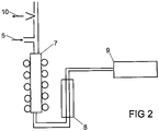
- figure 2 shows a portion of a device for carrying out the method figure 1 after the split and the addition of hydrogen 5 for step S5.
- Step S5 takes place in a reduction tube 7 heated to approximately 200° C. with a catalytic converter, not shown in detail.
- the measurement gas flows from the reduction tube 7 through a cooler 8, in which the water 6 according to figure 1 is discharged, and then reaches a detector 9, in which step S6 of determining the proportion of nitrogen in the gas mixture takes place.
- the detector 9 is a thermal conductivity detector.
Landscapes
- Health & Medical Sciences (AREA)
- Chemical & Material Sciences (AREA)
- Life Sciences & Earth Sciences (AREA)
- Physics & Mathematics (AREA)
- Combustion & Propulsion (AREA)
- Molecular Biology (AREA)
- Engineering & Computer Science (AREA)
- Analytical Chemistry (AREA)
- Biochemistry (AREA)
- General Health & Medical Sciences (AREA)
- General Physics & Mathematics (AREA)
- Immunology (AREA)
- Pathology (AREA)
- Investigating Or Analyzing Non-Biological Materials By The Use Of Chemical Means (AREA)
Description
- Die Erfindung betrifft ein Verfahren zum Bestimmen eines Stickstoffgehaltes in festen oder flüssigen Proben, wobei durch Oxidation der Probe ein Messgas erzeugt wird, dem Messgas ein Trägergas hinzugefügt wird und die Sauerstoff- und Stickoxidbestandteile im Messgas zu Wasser und Stickstoff umgewandelt werden, wobei in dem verbleibenden Stickstoff Trägergas Gemisch der Anteil des Stickstoffs detektiert wird.
- Der Proteingehalt in Nahrungsmitteln wie Weizen, Milch oder dergleichen wird im Regelfall über den Stickstoffgehalt einer Probe bestimmt. Der Stickstoffgehalt wird dann mittels eines geeigneten Faktors auf den Proteingehalt umgerechnet. Auch in Substraten wie beispielsweise Ackerböden ist der Stickstoffgehalt von Interesse, um auf diese Weise die Nährstoffeigenschaften des Substrates anhand einer Probe bestimmen zu können.
- Die
DE 35 38 778 A1 offenbart ein Verfahren und eine Vorrichtung zum Bestimmen des Gehalts an Stickstoff in einer Probe. Hierbei wird die Probe in einem mit Sauerstoff angereicherten, stickstofffreien, inerten Trägergas verbrannt. Als Trägergas wird CD2 verwendet. - Ein Verfahren zur Bestimmung von Kohlenstoff-, Wasserund Stickstoffgehalten in einem organischen Material ist beispielsweise aus der
US 4,525,328 C bekannt. Bei diesem Verfahren wird das organische Material verbrannt und ein Trägergas zugesetzt. Als Trägergas wird sehr kostenintensives Helium verwendet. - Dieses Verfahren wird auch als Dumas- Verfahren bezeichnet. Dabei wird eine Probe in einem sauerstoffhaltigen Trägergasstrom verbrannt, störende Verbrennungsprodukte adsorptiv entfernt und die unterschiedlichen Oxidationsprodukte des Stickstoffs durch chemische Reduktion beispielsweise an Kupfer oder Wolfram zu elementaren Stickstoff reduziert. Das Kupfer oder Wolfram muss auf etwa 600-700°C erwärmt werden. Bei der Reduktion der Sauerstoff- und Stickoxidbestandteile entsteht Kupferoxid oder Wolframoxid. Dieses Verfahren hat den wesentlichen Nachteil, dass sich das Reduktionsmittel durch Oxidation sehr schnell verbraucht und unter einer Unterbrechung des Analyseablaufs ersetzt werden muss. Dies führt zu einem großen Wartungsaufwand und zu hohen Kosten des Verfahrens.
- Der Erfindung liegt das Problem zugrunde, eine kontinuierliche Umsetzung von Stickstoffoxiden zu Stickstoff und Sauerstoffverbindungen zu ermöglichen.
- Dieses Problem wird erfindungsgemäß dadurch gelöst, dass zur Reduktion der Sauerstoff- und Stickoxidbestandteile dem Messgas Wasserstoff hinzugefügt wird und dass die Reduktion des Messgases an einem Katalysator erfolgt, wobei die Parameter Temperatur, Verweildauer, Art des Katalysators so gewählt werden, dass Stickstoff entsteht und eine weitergehende Reduktion zu Ammoniak vermieden wird.
- Das erfindungsgemäße Verfahren ist in Anspruch 1 definiert.
- Durch diese Gestaltung ermöglicht die Reduktion der Sauerstoff- und Stickoxidbestandteile im Messgas mittels Wasserstoff einen kontinuierlichen Verfahrensablauf. Dies führt zu einer wesentlichen Vereinfachung des Verfahrens, da kein manueller Eingriff in den Analyseablauf erforderlich ist. Der Sauerstoff im Messgas wird von dem zugesetzten Wasserstoff zu Wasser und Stickoxide zu Stickstoff und Wasser reduziert. Damit lassen sich die Stickstoffverbindungen zu Stickstoff und weiteren Verbrennungsprodukten umwandeln. Das erfindungsgemäße Verfahren gestaltet sich hierdurch besonders kostengünstig. Die Reduktion des Messgases lässt sich zuverlässig steuern, weil die Reduktion des Messgases an einem Katalysator erfolgt. Über Parameter, wie die Temperatur, die Verweildauer und die Art des Katalysators lassen sich die Produkte steuern. Im Falle der Reduktion des Messgases werden die Parameter derart gewählt, dass möglichst ausschließlich Stickstoff erzeugt wird, eine Weitergehende Reduktion zu Ammoniak ist zu vermeiden. Vorzugsweise werden Platin oder Platinmetalle, auch als Legierung, als Katalysator eingesetzt.
- Der Einsatz von Helium als Trägergas lässt sich gemäß einer anderen vorteilhaften Weiterbildung der Erfindung einfach vermeiden, wenn das Trägergas Wasserstoff ist, so dass dem Messgas mehr Wasserstoff zugeführt wird als für die Reduktion der Sauerstoff- und Stickoxidbestandteile notwendig ist. Durch diese Gestaltung werden auch die Sauerstoff- und Stickoxidbestandteile in dem Messgas bei Wasserstoffüberschuss umgesetzt, was einen zu einem besonders reproduzierbaren Verfahrensablauf führt.
- Eine Störung der Bestimmung durch verschiedene Gasbestandteile lassen sich gemäß einer anderen vorteilhaften Weiterbildung der Erfindung einfach vermeiden, wenn vor der Zuführung von Wasserstoff nichtstickstoffhaltige Gasbestandteile abgetrennt werden. Eine solche Abtrennung kann beispielsweise absorptiv oder chromatografisch erfolgen.
- Eine zuverlässige Oxidation der Probe lässt sich gemäß einer anderen vorteilhaften Weiterbildung der Erfindung einfach sicherstellen, wenn Oxidation der Probe in einem sauerstoffhaltigem Gas an einem Katalysator erfolgt.
- Der genaue Stickstoffgehalt in dem Stickstoff Trägergas Gemisch lässt sich gemäß einer anderen vorteilhaften Weiterbildung der Erfindung besonders einfach ermitteln, wenn die Detektion des Stickstoffs in dem Stickstoff Wasserstoff Gemisch durch die Ermittelung der Wärmeleitfähigkeit erfolgt.
- Die Konzentration der Elemente Kohlenstoff, Wasserstoff und Schwefel in der Ausgangsprobe lässt sich gemäß einer anderen vorteilhaften Weiterbildung der Erfindung einfach ermitteln, wenn nach der Oxidation der Probe und vor der Zugabe von Wasserstoff der Gehalt der Oxidationsprodukte Kohlendioxid, Schwefeldioxid und Wasser detektiert wird. Eine solche Detektion lässt sich mittels Wärmeleitfähigkeitsdetektion oder Infrarotdetektion einfach durchführen.
- Das Verfahren gestaltet sich gemäß einer anderen vorteilhaften Weiterbildung der Erfindung besonders kostengünstig, wenn nach der Oxidation ein Gassplit durchgeführt wird und der Wasserstoff ausschließlich einem vorgesehenen Bruchteil des Messgases zugeführt wird. Durch diese Gestaltung können übliche Probengrößen untersucht werden, ohne das gesamte entstehende Messgas zu untersuchen. Anstelle des gesamten Messgases werden beispielsweise nur 10% des Messgases untersucht und das Ergebnis auf die gesamte Probe umgerechnet.
- Bei der Reduktion der Stickstoffbestandteile entstehendes Wasser lässt sich gemäß einer anderen vorteilhaften Weiterbildung der Erfindung besonders kostengünstig abführen, wenn die Abtrennung von Wasser vor dem Detektieren des Stickstoffanteils im Stickstoff Trägergas Gemisch durch Kühlung erfolgt.
- Die Erfindung lässt zahlreiche Ausführungsformen zu. Zur weiteren Verdeutlichung ihres Grundprinzips ist eine davon in der Zeichnung dargestellt und wird nachfolgend beschrieben. Diese zeigt in
- Fig.1
- ein Flussdiagramm mit einzelnen Schritten eines Verfahrens zum Bestimmen eines Stickstoffgehaltes,
- Fig.2
- schematisch einen Teilbereich einer Vorrichtung zur Durchführung des Verfahrens aus
Figur 1 . -
Figur 1 zeigt ein Verfahren zum Bestimmen eines Stickstoffgehaltes in einer festen oder flüssigen Probe 1. Die Probe wird in einem ersten Schritt S1 in eine geeignete Verpackung, im vorliegenden Fall einen Tiegel 2 gegeben und einem Verbrennungsofen zugeführt. In einem Schritt S2 erfolgt die Verbrennung der Probe bei Zuführung eines sauerstoffhaltigem Gasstroms 3 an einem nicht näher dargestellten Katalysator. In einem Schritt S3 erfolgt die Bestimmung von Kohlendioxid, Schwefeldioxid oder Wasser in einem geeigneten Detektor, beispielsweise einem Infrarotdetektor. Nach einer Abtrennung von nicht stickstoffhaltigen Gasbestandteilen 10 wie Kohlendioxid, Schwefeldioxid und Wasser in einem Schritt S4 erfolgt ein Split des Messgases. Ein Teilstrom 4 des Messgases wird abgeführt und ein kleinerer Teil einer Reduktion in einem Schritt S5 hinzugefügt. Die Reduktion des Messgases erfolgt an einem nicht näher dargestellten Katalysator unter Hinzugabe von Wasserstoff 5. Nach dem Schritt S5 wird noch vorhandenes Wasser 6 aus dem Messgas abgeführt. Es verbleibt eine Trägergas/ Stickstoffmischung, die in einem Schritt S6 analysiert wird. Da als Trägergas Wasserstoff eingesetzt wurde handelt es sich um eine Wasserstoff/Stickstoffmischung. Bei dieser Analyse wird der Gehalt von Stickstoff in der Mischung erfasst. Dieser Gehalt von Stickstoff ist bei Kenntnis der Abgeführten und zugeführten Masseanteilen ein Maß für den Stickstoffanteil in der Probe. -
Figur 2 zeigt einen Teilbereich einer Vorrichtung zur Durchführung des Verfahrens nachFigur 1 nach dem Split und der Hinzuführung von Wasserstoff 5 für den Schritt S5. Der Schritt S5 findet in einem auf etwa 200°C beheizten Reduktionsrohr 7 mit einem nicht näher dargestellten Katalysator statt. Das Messgas fließt aus dem Reduktionsrohr 7 durch einen Kühler 8, in dem das Wasser 6 gemäßFigur 1 abgeführt wird, und gelangt anschließend in einen Detektor 9, in dem der Schritt S6 der Ermittlung des Stickstoffanteils in dem Gasgemisch erfolgt. Bei dem Detektor 9 handelt es sich um einen Wärmeleitfähigkeitsdetektor.
Claims (8)
- Verfahren zum Bestimmen eines Stickstoffgehaltes in festen oder flüssigen Proben (1), wobei durch Oxidation der Probe (1) im Sauerstoffstrom ein Messgas erzeugt wird, dem Messgas ein Trägergas hinzugefügt wird und die Sauerstoff- und Stickoxidbestandteile im Messgas zu Wasser (6) und Stickstoff umgewandelt werden, wobei in dem verbleibenden Stickstoff Trägergas Gemisch der Anteil des Stickstoffs detektiert wird, dadurch gekennzeichnet,
dass zur Reduktion der Sauerstoff- und Stickoxidbestandteile dem Messgas Wasserstoff (5) als Trägergas hinzugefügt wird und dass die Reduktion des Messgases an einem Katalysator erfolgt, wobei die Parameter Temperatur, Verweildauer, Art des Katalysators so gewählt werden, dass Stickstoff entsteht und eine weitere Reduktion zu Ammoniak vermieden wird. - Verfahren nach Anspruch 1, dadurch gekennzeichnet, dass das Trägergas Wasserstoff (5) ist, so dass dem Messgas mehr Wasserstoff (5) zugeführt wird als für die Reduktion der Sauerstoff- und Stickoxidbestandteile notwendig ist.
- Verfahren nach Anspruch l oder 2, dadurch gekennzeichnet, dass vor der Zuführung von Wasserstoff (5) nichtstickstoffhaltige Gasbestandteile (10) abgetrennt werden.
- Verfahren nach einem der Ansprüche 1 bis 3, dadurch gekennzeichnet, dass Oxidation der Probe (1) in einem sauerstoffhaltigem Gas (3) an einem Katalysator erfolgt.
- Verfahren nach einem der Ansprüche 1 bis 4, dadurch gekennzeichnet, dass die Detektion des Stickstoffs in dem Stickstoff Wasserstoff Gemisch durch die Ermittelung der Wärmeleitfähigkeit erfolgt.
- Verfahren nach einem der Ansprüche 1 bis 5, dadurch gekennzeichnet, dass nach der Oxidation der Probe und vor der Zugabe von Wasserstoff (5) der Gehalt der Oxidationsprodukte Kohlendioxid, Schwefeldioxid und Wasser detektiert wird.
- Verfahren nach einem der Ansprüche 1 bis 6, dadurch gekennzeichnet, dass nach der Oxidation ein Gassplit durchgeführt wird und der Wasserstoff (5) ausschließlich einem vorgesehenen Bruchteil des Messgases zugeführt wird.
- Verfahren nach einem der Ansprüche 1 bis 7, dadurch gekennzeichnet, dass die Abtrennung von Wasser (6) vor dem Detektieren des Stickstoffanteils im Stickstoff Trägergas Gemisch durch Kühlung erfolgt.
Applications Claiming Priority (2)
| Application Number | Priority Date | Filing Date | Title |
|---|---|---|---|
| DE102017002627.0A DE102017002627A1 (de) | 2017-03-20 | 2017-03-20 | Verfahren zum Bestimmen eines Stickstoffgehaltes in festen oder flüssigen Proben |
| PCT/DE2018/100241 WO2018171836A1 (de) | 2017-03-20 | 2018-03-20 | Verfahren zum bestimmen eines stickstoffgehaltes in festen oder flüssigen proben |
Publications (2)
| Publication Number | Publication Date |
|---|---|
| EP3615929A1 EP3615929A1 (de) | 2020-03-04 |
| EP3615929B1 true EP3615929B1 (de) | 2023-01-25 |
Family
ID=62244259
Family Applications (1)
| Application Number | Title | Priority Date | Filing Date |
|---|---|---|---|
| EP18726906.3A Active EP3615929B1 (de) | 2017-03-20 | 2018-03-20 | Verfahren zum bestimmen eines stickstoffgehaltes in festen oder flüssigen proben |
Country Status (3)
| Country | Link |
|---|---|
| EP (1) | EP3615929B1 (de) |
| DE (1) | DE102017002627A1 (de) |
| WO (1) | WO2018171836A1 (de) |
Family Cites Families (8)
| Publication number | Priority date | Publication date | Assignee | Title |
|---|---|---|---|---|
| US4332591A (en) * | 1978-01-19 | 1982-06-01 | Sumitomo Chemical Company, Limited | Analytical method and apparatus for the determination of total nitrogen contents in aqueous systems |
| US4525328A (en) | 1982-03-05 | 1985-06-25 | Leco Corporation | Carbon, hydrogen, and nitrogen analyzer |
| DE3538778A1 (de) * | 1985-10-31 | 1987-05-07 | Heraeus Gmbh W C | Verfahren und vorrichtung zum bestimmen des gehalts an stickstoff in einer probe |
| US5916523A (en) * | 1996-12-04 | 1999-06-29 | Antek Instruments, Inc. | Methods for near simultaneous chemiluminescent sulfur and nitrogen detection |
| DE19741810B4 (de) * | 1997-09-23 | 2005-09-15 | Ech Elektrochemie Halle Gmbh | Verfahren zur Gesamtstickstoffbestimmung |
| DE102010028211B4 (de) * | 2010-04-26 | 2011-11-24 | Carl Von Ossietzky Universität Oldenburg | Verfahren und Vorrichtung zur Detektion von Wasserstoff |
| DE102014002266B3 (de) * | 2014-02-20 | 2015-03-19 | Elementar Analysensysteme Gmbh | Verfahren und Vorrichtung zur Analyse von Stickstoff (N) in einer Probe |
| DE102014012914A1 (de) * | 2014-09-05 | 2016-03-10 | Elementar Analysensysteme Gmbh | Verfahren sowie Analysegeräte für die wahlweise Analyse von einem oder mehreren der Elemente Kohlenstoff (C), Schwefel (S), Stickstoff (N), Sauerstoff (O) und Wasserstoff (H) in Metallen oder anderen anorganischen Proben |
-
2017
- 2017-03-20 DE DE102017002627.0A patent/DE102017002627A1/de not_active Withdrawn
-
2018
- 2018-03-20 EP EP18726906.3A patent/EP3615929B1/de active Active
- 2018-03-20 WO PCT/DE2018/100241 patent/WO2018171836A1/de not_active Ceased
Also Published As
| Publication number | Publication date |
|---|---|
| WO2018171836A1 (de) | 2018-09-27 |
| DE102017002627A1 (de) | 2018-09-20 |
| EP3615929A1 (de) | 2020-03-04 |
Similar Documents
| Publication | Publication Date | Title |
|---|---|---|
| DE69520425T2 (de) | Verfahren zur isotopenzusammensetzungsanalyse und isotopenzusammensetzungsanalysator | |
| DE69016900T2 (de) | Analysator von Isotopenzusammensetzungen. | |
| DE102014012914A1 (de) | Verfahren sowie Analysegeräte für die wahlweise Analyse von einem oder mehreren der Elemente Kohlenstoff (C), Schwefel (S), Stickstoff (N), Sauerstoff (O) und Wasserstoff (H) in Metallen oder anderen anorganischen Proben | |
| DE102010022017A1 (de) | Verfahren zur Probenvorbereitung bei chromatographischen Trennmethoden und Vorrichtungen zur Durchführung einer Probenvorbereitung | |
| DE2218776A1 (de) | Vorrichtung und Verfahren zur Analyse des Gehalts von Luft an Pollutionssubstanzen | |
| EP0971225A2 (de) | Verfahren zum Nachweis eines Produktes im Abstrom eines katalytischen Materials einer Vielzahl von katalytischen Materialien | |
| WO2012016624A1 (de) | Bestimmung der isotopenverhältnisse von kohlenstoff und stickstoff in wasserproben | |
| DE2520444A1 (de) | Verfahren und vorrichtung zum kontinuierlichen messen der wasserstoffkonzentration in argongas | |
| EP1707253B1 (de) | Verfahren und Vorrichtung zur Bestimmung von Isotopenverhältnissen leichter Elemente in einem Analyseablauf | |
| KR20180114898A (ko) | 산화성 화합물 중 산소의 검출 및 정량화 방법 | |
| DE102010039275B4 (de) | Verfahren und Vorrichtung zur online-Bestimmung des Isotopenverhältnisses von Chlor, Brom oder Schwefel in einer organischen Probe | |
| DE69228519T2 (de) | Verfahren und Vorrichtung zur analytischen Bestimmung von Halogenen,Schwetel undPhosphor | |
| EP3338085A1 (de) | Verfahren zur elementaranalyse | |
| EP2210087B1 (de) | Verfahren und vorrichtung zur isotopenverhältnisanalyse | |
| EP3108240B1 (de) | Analysator für die analyse von kohlenstoff (c) und schwefel (s) in metallen | |
| WO2018171836A1 (de) | Verfahren zum bestimmen eines stickstoffgehaltes in festen oder flüssigen proben | |
| DE3538778A1 (de) | Verfahren und vorrichtung zum bestimmen des gehalts an stickstoff in einer probe | |
| EP3791174B1 (de) | Verwendung einer zufuhreinrichtung zum einführen von proben in eine vorrichtung | |
| DE4231510C2 (de) | Verfahren zur Analyse von organischen Proben | |
| DE19644051C2 (de) | Verfahren und Einrichtung zur Überwachung und Kennwert-Bestimmung von Gasmischungen bei Nitrocarburier- und Nitrier-Prozessen in der Härtereitechnik | |
| DE102014002266B3 (de) | Verfahren und Vorrichtung zur Analyse von Stickstoff (N) in einer Probe | |
| DE102010028211B4 (de) | Verfahren und Vorrichtung zur Detektion von Wasserstoff | |
| DE2449143A1 (de) | Verfahren zur bestimmung von gasen | |
| DE102008008288A1 (de) | Verfahren zur Sauerstoffelementaranalyse und zur Sauerstoffisotopenmessung stickstoffhaltiger, organischer Substanzen | |
| DE19741811B4 (de) | Verfahren zur Gesamt-Organohalogenbestimmung |
Legal Events
| Date | Code | Title | Description |
|---|---|---|---|
| STAA | Information on the status of an ep patent application or granted ep patent |
Free format text: STATUS: UNKNOWN |
|
| STAA | Information on the status of an ep patent application or granted ep patent |
Free format text: STATUS: THE INTERNATIONAL PUBLICATION HAS BEEN MADE |
|
| PUAI | Public reference made under article 153(3) epc to a published international application that has entered the european phase |
Free format text: ORIGINAL CODE: 0009012 |
|
| STAA | Information on the status of an ep patent application or granted ep patent |
Free format text: STATUS: REQUEST FOR EXAMINATION WAS MADE |
|
| 17P | Request for examination filed |
Effective date: 20200117 |
|
| AK | Designated contracting states |
Kind code of ref document: A1 Designated state(s): AL AT BE BG CH CY CZ DE DK EE ES FI FR GB GR HR HU IE IS IT LI LT LU LV MC MK MT NL NO PL PT RO RS SE SI SK SM TR |
|
| AX | Request for extension of the european patent |
Extension state: BA ME |
|
| DAV | Request for validation of the european patent (deleted) | ||
| DAX | Request for extension of the european patent (deleted) | ||
| GRAP | Despatch of communication of intention to grant a patent |
Free format text: ORIGINAL CODE: EPIDOSNIGR1 |
|
| STAA | Information on the status of an ep patent application or granted ep patent |
Free format text: STATUS: GRANT OF PATENT IS INTENDED |
|
| INTG | Intention to grant announced |
Effective date: 20220823 |
|
| GRAS | Grant fee paid |
Free format text: ORIGINAL CODE: EPIDOSNIGR3 |
|
| GRAA | (expected) grant |
Free format text: ORIGINAL CODE: 0009210 |
|
| STAA | Information on the status of an ep patent application or granted ep patent |
Free format text: STATUS: THE PATENT HAS BEEN GRANTED |
|
| AK | Designated contracting states |
Kind code of ref document: B1 Designated state(s): AL AT BE BG CH CY CZ DE DK EE ES FI FR GB GR HR HU IE IS IT LI LT LU LV MC MK MT NL NO PL PT RO RS SE SI SK SM TR |
|
| REG | Reference to a national code |
Ref country code: GB Ref legal event code: FG4D Free format text: NOT ENGLISH |
|
| REG | Reference to a national code |
Ref country code: CH Ref legal event code: EP |
|
| REG | Reference to a national code |
Ref country code: DE Ref legal event code: R096 Ref document number: 502018011510 Country of ref document: DE |
|
| REG | Reference to a national code |
Ref country code: AT Ref legal event code: REF Ref document number: 1546233 Country of ref document: AT Kind code of ref document: T Effective date: 20230215 Ref country code: IE Ref legal event code: FG4D Free format text: LANGUAGE OF EP DOCUMENT: GERMAN |
|
| REG | Reference to a national code |
Ref country code: LT Ref legal event code: MG9D |
|
| REG | Reference to a national code |
Ref country code: NL Ref legal event code: MP Effective date: 20230125 |
|
| PG25 | Lapsed in a contracting state [announced via postgrant information from national office to epo] |
Ref country code: NL Free format text: LAPSE BECAUSE OF FAILURE TO SUBMIT A TRANSLATION OF THE DESCRIPTION OR TO PAY THE FEE WITHIN THE PRESCRIBED TIME-LIMIT Effective date: 20230125 |
|
| PG25 | Lapsed in a contracting state [announced via postgrant information from national office to epo] |
Ref country code: RS Free format text: LAPSE BECAUSE OF FAILURE TO SUBMIT A TRANSLATION OF THE DESCRIPTION OR TO PAY THE FEE WITHIN THE PRESCRIBED TIME-LIMIT Effective date: 20230125 Ref country code: PT Free format text: LAPSE BECAUSE OF FAILURE TO SUBMIT A TRANSLATION OF THE DESCRIPTION OR TO PAY THE FEE WITHIN THE PRESCRIBED TIME-LIMIT Effective date: 20230525 Ref country code: NO Free format text: LAPSE BECAUSE OF FAILURE TO SUBMIT A TRANSLATION OF THE DESCRIPTION OR TO PAY THE FEE WITHIN THE PRESCRIBED TIME-LIMIT Effective date: 20230425 Ref country code: LV Free format text: LAPSE BECAUSE OF FAILURE TO SUBMIT A TRANSLATION OF THE DESCRIPTION OR TO PAY THE FEE WITHIN THE PRESCRIBED TIME-LIMIT Effective date: 20230125 Ref country code: LT Free format text: LAPSE BECAUSE OF FAILURE TO SUBMIT A TRANSLATION OF THE DESCRIPTION OR TO PAY THE FEE WITHIN THE PRESCRIBED TIME-LIMIT Effective date: 20230125 Ref country code: HR Free format text: LAPSE BECAUSE OF FAILURE TO SUBMIT A TRANSLATION OF THE DESCRIPTION OR TO PAY THE FEE WITHIN THE PRESCRIBED TIME-LIMIT Effective date: 20230125 Ref country code: ES Free format text: LAPSE BECAUSE OF FAILURE TO SUBMIT A TRANSLATION OF THE DESCRIPTION OR TO PAY THE FEE WITHIN THE PRESCRIBED TIME-LIMIT Effective date: 20230125 |
|
| PG25 | Lapsed in a contracting state [announced via postgrant information from national office to epo] |
Ref country code: SE Free format text: LAPSE BECAUSE OF FAILURE TO SUBMIT A TRANSLATION OF THE DESCRIPTION OR TO PAY THE FEE WITHIN THE PRESCRIBED TIME-LIMIT Effective date: 20230125 Ref country code: PL Free format text: LAPSE BECAUSE OF FAILURE TO SUBMIT A TRANSLATION OF THE DESCRIPTION OR TO PAY THE FEE WITHIN THE PRESCRIBED TIME-LIMIT Effective date: 20230125 Ref country code: IS Free format text: LAPSE BECAUSE OF FAILURE TO SUBMIT A TRANSLATION OF THE DESCRIPTION OR TO PAY THE FEE WITHIN THE PRESCRIBED TIME-LIMIT Effective date: 20230525 Ref country code: GR Free format text: LAPSE BECAUSE OF FAILURE TO SUBMIT A TRANSLATION OF THE DESCRIPTION OR TO PAY THE FEE WITHIN THE PRESCRIBED TIME-LIMIT Effective date: 20230426 Ref country code: FI Free format text: LAPSE BECAUSE OF FAILURE TO SUBMIT A TRANSLATION OF THE DESCRIPTION OR TO PAY THE FEE WITHIN THE PRESCRIBED TIME-LIMIT Effective date: 20230125 |
|
| REG | Reference to a national code |
Ref country code: DE Ref legal event code: R119 Ref document number: 502018011510 Country of ref document: DE |
|
| PG25 | Lapsed in a contracting state [announced via postgrant information from national office to epo] |
Ref country code: SM Free format text: LAPSE BECAUSE OF FAILURE TO SUBMIT A TRANSLATION OF THE DESCRIPTION OR TO PAY THE FEE WITHIN THE PRESCRIBED TIME-LIMIT Effective date: 20230125 Ref country code: RO Free format text: LAPSE BECAUSE OF FAILURE TO SUBMIT A TRANSLATION OF THE DESCRIPTION OR TO PAY THE FEE WITHIN THE PRESCRIBED TIME-LIMIT Effective date: 20230125 Ref country code: MC Free format text: LAPSE BECAUSE OF FAILURE TO SUBMIT A TRANSLATION OF THE DESCRIPTION OR TO PAY THE FEE WITHIN THE PRESCRIBED TIME-LIMIT Effective date: 20230125 Ref country code: EE Free format text: LAPSE BECAUSE OF FAILURE TO SUBMIT A TRANSLATION OF THE DESCRIPTION OR TO PAY THE FEE WITHIN THE PRESCRIBED TIME-LIMIT Effective date: 20230125 Ref country code: DK Free format text: LAPSE BECAUSE OF FAILURE TO SUBMIT A TRANSLATION OF THE DESCRIPTION OR TO PAY THE FEE WITHIN THE PRESCRIBED TIME-LIMIT Effective date: 20230125 Ref country code: CZ Free format text: LAPSE BECAUSE OF FAILURE TO SUBMIT A TRANSLATION OF THE DESCRIPTION OR TO PAY THE FEE WITHIN THE PRESCRIBED TIME-LIMIT Effective date: 20230125 |
|
| REG | Reference to a national code |
Ref country code: CH Ref legal event code: PL |
|
| PG25 | Lapsed in a contracting state [announced via postgrant information from national office to epo] |
Ref country code: SK Free format text: LAPSE BECAUSE OF FAILURE TO SUBMIT A TRANSLATION OF THE DESCRIPTION OR TO PAY THE FEE WITHIN THE PRESCRIBED TIME-LIMIT Effective date: 20230125 |
|
| REG | Reference to a national code |
Ref country code: BE Ref legal event code: MM Effective date: 20230331 |
|
| PLBE | No opposition filed within time limit |
Free format text: ORIGINAL CODE: 0009261 |
|
| STAA | Information on the status of an ep patent application or granted ep patent |
Free format text: STATUS: NO OPPOSITION FILED WITHIN TIME LIMIT |
|
| GBPC | Gb: european patent ceased through non-payment of renewal fee |
Effective date: 20230425 |
|
| PG25 | Lapsed in a contracting state [announced via postgrant information from national office to epo] |
Ref country code: LU Free format text: LAPSE BECAUSE OF NON-PAYMENT OF DUE FEES Effective date: 20230320 |
|
| 26N | No opposition filed |
Effective date: 20231026 |
|
| REG | Reference to a national code |
Ref country code: IE Ref legal event code: MM4A |
|
| PG25 | Lapsed in a contracting state [announced via postgrant information from national office to epo] |
Ref country code: GB Free format text: LAPSE BECAUSE OF NON-PAYMENT OF DUE FEES Effective date: 20230425 |
|
| PG25 | Lapsed in a contracting state [announced via postgrant information from national office to epo] |
Ref country code: SI Free format text: LAPSE BECAUSE OF FAILURE TO SUBMIT A TRANSLATION OF THE DESCRIPTION OR TO PAY THE FEE WITHIN THE PRESCRIBED TIME-LIMIT Effective date: 20230125 Ref country code: LI Free format text: LAPSE BECAUSE OF NON-PAYMENT OF DUE FEES Effective date: 20230331 Ref country code: IE Free format text: LAPSE BECAUSE OF NON-PAYMENT OF DUE FEES Effective date: 20230320 Ref country code: GB Free format text: LAPSE BECAUSE OF NON-PAYMENT OF DUE FEES Effective date: 20230425 Ref country code: FR Free format text: LAPSE BECAUSE OF NON-PAYMENT OF DUE FEES Effective date: 20230325 Ref country code: DE Free format text: LAPSE BECAUSE OF NON-PAYMENT OF DUE FEES Effective date: 20231003 Ref country code: CH Free format text: LAPSE BECAUSE OF NON-PAYMENT OF DUE FEES Effective date: 20230331 |
|
| PG25 | Lapsed in a contracting state [announced via postgrant information from national office to epo] |
Ref country code: BE Free format text: LAPSE BECAUSE OF NON-PAYMENT OF DUE FEES Effective date: 20230331 |
|
| REG | Reference to a national code |
Ref country code: AT Ref legal event code: MM01 Ref document number: 1546233 Country of ref document: AT Kind code of ref document: T Effective date: 20230320 |
|
| PG25 | Lapsed in a contracting state [announced via postgrant information from national office to epo] |
Ref country code: IT Free format text: LAPSE BECAUSE OF FAILURE TO SUBMIT A TRANSLATION OF THE DESCRIPTION OR TO PAY THE FEE WITHIN THE PRESCRIBED TIME-LIMIT Effective date: 20230125 |
|
| PG25 | Lapsed in a contracting state [announced via postgrant information from national office to epo] |
Ref country code: AT Free format text: LAPSE BECAUSE OF NON-PAYMENT OF DUE FEES Effective date: 20230320 |
|
| PG25 | Lapsed in a contracting state [announced via postgrant information from national office to epo] |
Ref country code: AT Free format text: LAPSE BECAUSE OF NON-PAYMENT OF DUE FEES Effective date: 20230320 |
|
| PG25 | Lapsed in a contracting state [announced via postgrant information from national office to epo] |
Ref country code: BG Free format text: LAPSE BECAUSE OF FAILURE TO SUBMIT A TRANSLATION OF THE DESCRIPTION OR TO PAY THE FEE WITHIN THE PRESCRIBED TIME-LIMIT Effective date: 20230125 |
|
| PG25 | Lapsed in a contracting state [announced via postgrant information from national office to epo] |
Ref country code: BG Free format text: LAPSE BECAUSE OF FAILURE TO SUBMIT A TRANSLATION OF THE DESCRIPTION OR TO PAY THE FEE WITHIN THE PRESCRIBED TIME-LIMIT Effective date: 20230125 |
|
| PG25 | Lapsed in a contracting state [announced via postgrant information from national office to epo] |
Ref country code: CY Free format text: LAPSE BECAUSE OF FAILURE TO SUBMIT A TRANSLATION OF THE DESCRIPTION OR TO PAY THE FEE WITHIN THE PRESCRIBED TIME-LIMIT; INVALID AB INITIO Effective date: 20180320 |
|
| PG25 | Lapsed in a contracting state [announced via postgrant information from national office to epo] |
Ref country code: HU Free format text: LAPSE BECAUSE OF FAILURE TO SUBMIT A TRANSLATION OF THE DESCRIPTION OR TO PAY THE FEE WITHIN THE PRESCRIBED TIME-LIMIT; INVALID AB INITIO Effective date: 20180320 |
|
| PG25 | Lapsed in a contracting state [announced via postgrant information from national office to epo] |
Ref country code: TR Free format text: LAPSE BECAUSE OF FAILURE TO SUBMIT A TRANSLATION OF THE DESCRIPTION OR TO PAY THE FEE WITHIN THE PRESCRIBED TIME-LIMIT Effective date: 20230125 |