EP3615867B1 - Steuerverfahren für eine kochvorrichtung - Google Patents
Steuerverfahren für eine kochvorrichtung Download PDFInfo
- Publication number
- EP3615867B1 EP3615867B1 EP18802940.9A EP18802940A EP3615867B1 EP 3615867 B1 EP3615867 B1 EP 3615867B1 EP 18802940 A EP18802940 A EP 18802940A EP 3615867 B1 EP3615867 B1 EP 3615867B1
- Authority
- EP
- European Patent Office
- Prior art keywords
- water
- steam generator
- steam
- level
- supplied
- Prior art date
- Legal status (The legal status is an assumption and is not a legal conclusion. Google has not performed a legal analysis and makes no representation as to the accuracy of the status listed.)
- Active
Links
Images



Classifications
-
- A—HUMAN NECESSITIES
- A47—FURNITURE; DOMESTIC ARTICLES OR APPLIANCES; COFFEE MILLS; SPICE MILLS; SUCTION CLEANERS IN GENERAL
- A47J—KITCHEN EQUIPMENT; COFFEE MILLS; SPICE MILLS; APPARATUS FOR MAKING BEVERAGES
- A47J27/00—Cooking-vessels
- A47J27/04—Cooking-vessels for cooking food in steam; Devices for extracting fruit juice by means of steam ; Vacuum cooking vessels
-
- F—MECHANICAL ENGINEERING; LIGHTING; HEATING; WEAPONS; BLASTING
- F24—HEATING; RANGES; VENTILATING
- F24C—DOMESTIC STOVES OR RANGES ; DETAILS OF DOMESTIC STOVES OR RANGES, OF GENERAL APPLICATION
- F24C7/00—Stoves or ranges heated by electric energy
- F24C7/08—Arrangement or mounting of control or safety devices
- F24C7/082—Arrangement or mounting of control or safety devices on ranges, e.g. control panels, illumination
- F24C7/085—Arrangement or mounting of control or safety devices on ranges, e.g. control panels, illumination on baking ovens
-
- A—HUMAN NECESSITIES
- A23—FOODS OR FOODSTUFFS; TREATMENT THEREOF, NOT COVERED BY OTHER CLASSES
- A23L—FOODS, FOODSTUFFS OR NON-ALCOHOLIC BEVERAGES, NOT OTHERWISE PROVIDED FOR; PREPARATION OR TREATMENT THEREOF
- A23L5/00—Preparation or treatment of foods or foodstuffs, in general; Food or foodstuffs obtained thereby; Materials therefor
- A23L5/10—General methods of cooking foods, e.g. by roasting or frying
- A23L5/13—General methods of cooking foods, e.g. by roasting or frying using water or steam
-
- A—HUMAN NECESSITIES
- A47—FURNITURE; DOMESTIC ARTICLES OR APPLIANCES; COFFEE MILLS; SPICE MILLS; SUCTION CLEANERS IN GENERAL
- A47J—KITCHEN EQUIPMENT; COFFEE MILLS; SPICE MILLS; APPARATUS FOR MAKING BEVERAGES
- A47J36/00—Parts, details or accessories of cooking-vessels
-
- F—MECHANICAL ENGINEERING; LIGHTING; HEATING; WEAPONS; BLASTING
- F24—HEATING; RANGES; VENTILATING
- F24C—DOMESTIC STOVES OR RANGES ; DETAILS OF DOMESTIC STOVES OR RANGES, OF GENERAL APPLICATION
- F24C13/00—Stoves or ranges with additional provisions for heating water
-
- F—MECHANICAL ENGINEERING; LIGHTING; HEATING; WEAPONS; BLASTING
- F24—HEATING; RANGES; VENTILATING
- F24C—DOMESTIC STOVES OR RANGES ; DETAILS OF DOMESTIC STOVES OR RANGES, OF GENERAL APPLICATION
- F24C15/00—Details
- F24C15/003—Details moisturising of air
-
- F—MECHANICAL ENGINEERING; LIGHTING; HEATING; WEAPONS; BLASTING
- F24—HEATING; RANGES; VENTILATING
- F24C—DOMESTIC STOVES OR RANGES ; DETAILS OF DOMESTIC STOVES OR RANGES, OF GENERAL APPLICATION
- F24C15/00—Details
- F24C15/32—Arrangements of ducts for hot gases, e.g. in or around baking ovens
- F24C15/322—Arrangements of ducts for hot gases, e.g. in or around baking ovens with forced circulation
- F24C15/327—Arrangements of ducts for hot gases, e.g. in or around baking ovens with forced circulation with air moisturising
-
- F—MECHANICAL ENGINEERING; LIGHTING; HEATING; WEAPONS; BLASTING
- F24—HEATING; RANGES; VENTILATING
- F24C—DOMESTIC STOVES OR RANGES ; DETAILS OF DOMESTIC STOVES OR RANGES, OF GENERAL APPLICATION
- F24C7/00—Stoves or ranges heated by electric energy
- F24C7/006—Stoves or ranges heated by electric energy using electrically heated liquids
-
- A—HUMAN NECESSITIES
- A23—FOODS OR FOODSTUFFS; TREATMENT THEREOF, NOT COVERED BY OTHER CLASSES
- A23V—INDEXING SCHEME RELATING TO FOODS, FOODSTUFFS OR NON-ALCOHOLIC BEVERAGES AND LACTIC OR PROPIONIC ACID BACTERIA USED IN FOODSTUFFS OR FOOD PREPARATION
- A23V2002/00—Food compositions, function of food ingredients or processes for food or foodstuffs
-
- A—HUMAN NECESSITIES
- A47—FURNITURE; DOMESTIC ARTICLES OR APPLIANCES; COFFEE MILLS; SPICE MILLS; SUCTION CLEANERS IN GENERAL
- A47J—KITCHEN EQUIPMENT; COFFEE MILLS; SPICE MILLS; APPARATUS FOR MAKING BEVERAGES
- A47J27/00—Cooking-vessels
- A47J27/04—Cooking-vessels for cooking food in steam; Devices for extracting fruit juice by means of steam ; Vacuum cooking vessels
- A47J2027/043—Cooking-vessels for cooking food in steam; Devices for extracting fruit juice by means of steam ; Vacuum cooking vessels for cooking food in steam
-
- A—HUMAN NECESSITIES
- A47—FURNITURE; DOMESTIC ARTICLES OR APPLIANCES; COFFEE MILLS; SPICE MILLS; SUCTION CLEANERS IN GENERAL
- A47J—KITCHEN EQUIPMENT; COFFEE MILLS; SPICE MILLS; APPARATUS FOR MAKING BEVERAGES
- A47J2203/00—Devices having filling level indicating means
Definitions
- Embodiments of the present disclosure relate to a control method of a cooking apparatus configured to control a steam generation amount.
- the cooking apparatus includes a steam supplier for supplying steam to a cooking compartment in which food is cooked.
- the steam supplier includes a water storage unit for storing water, and a steam generator for generating steam by heating the water delivered from the water storage unit.
- the steam supplier allows foods in the cooking compartment to be cooked by supplying the steam, which is generated by the steam generator, to the cooking compartment.
- US2016/061458A1 discloses an oven steam injection system including a steam generator having a heater reservoir and a heating element that is operable to heat water within the heater reservoir to generate steam.
- EP2375169A1 discloses an oven having a steam generator and a water reservoir comprising a water circulation pipe guiding device hydraulically connecting a water filling slide to the water reservoir.
- FR2958725A1 discloses a cooking appliance having a cooking cavity placed in a body and a steam generator producing steam to diffuse in the cavity. The appliance further comprises a water filling box supplying water to the steam generator by a hydraulic system, and a device for the draining the hydraulic system.
- EP2703740A1 discloses a cooking apparatus comprising a steam generator capable of preventing water inflow into a cooking compartment and easily discharging water therefrom.
- it is an aspect of the present disclosure is to provide a control method of a cooking apparatus capable of increasing a steam generation amount per unit by supplying water to a bottom surface of a cooking compartment and heating the water in the bottom surface using a heater.
- the cooking apparatus may further include a water level sensor configured to collect water level information related to the water in the steam generator, and the control method may further include collecting, by the water level sensor, water level information related to the water supplied to the steam generator.
- the controlling of the operation of the drain pump may include controlling the drain pump for a period of time to discharge the water present in the steam generator.
- the control method may further include controlling the water supply pump to additionally supply water to the steam generator when the level of the water supplied to the steam generator reaches the position.
- the controlling of the operation of the water supply pump to additionally supply water to the steam generator may include controlling the water supply pump for a period of time.
- the control method may further include controlling the operation of the drain pump to discharge the water in the steam generator when the period of time expires.
- the controlling of the operation of the drain pump to discharge the water in the steam generator may include controlling the drain pump to allow the level of water supplied to the steam generator to reach the position again.
- the position of the level of the water is a first position and the controlling of the operation of the drain pump to discharge the water in the steam generator may include controlling the operation of the drain pump to allow the level of water supplied to the steam generator to reach a second position.
- a control method of a cooking apparatus includes controlling an operation of a water supply pump to supply water to a steam generator; controlling the operation of the water supply pump for a period of time to supply water to the steam generator subsequent to a level of water supplied to the steam generator reaches a third predetermined position; controlling an operation of a drain pump to discharge water from the steam generator when the period of time expires; and controlling an operation of a steam heater installed in the steam generator and a bottom heater installed on a bottom surface of the cooking apparatus, respectively, when the level of water in the steam generator reaches the position at which the water is discharged from the steam generator.
- the period of time to supply water to the steam generator is a first period of time
- controlling of the operation of the steam heater and the bottom heater may include controlling the steam heater and the bottom heater for a second period of time.
- the control method may further include controlling the operation of the drain pump to discharge the water from the steam generator when the second period of time is expired.
- the control method may further include collecting, by a water level sensor, water level information related to water supplied to the steam generator.
- the control method may further include supplying water, which is supplied to the steam generator, into an inside of a cooking compartment of the cooking apparatus.
- a control method of a cooking apparatus is provided with a storage container configured to store water, a steam generator installed below a lower side of the storage container to receive the water from the storage container, a water supply pump installed above an upper side of the storage container to supply the water from the storage container to the steam generator, and a drain pump installed above the upper side of the storage container to discharge the water from the steam generator to the storage container.
- the control method includes controlling an operation of the water supply pump to supply water from the storage container to the steam generator; controlling an operation of the drain pump to discharge water in the steam generator when a level of water supplied to the steam generator reaches a position; controlling the operation of the water supply pump for a period of time to supply water to the steam generator subsequent to a level of water supplied to the steam generator reaching another position; controlling the operation of the drain pump to discharge the water from the steam generator when the third period of time expires; and controlling an operation of a steam heater installed in the steam generator and a bottom heater installed on a bottom surface of the cooking apparatus, respectively, when the level of the water in the steam generator reaches the position at which the water is discharged from the steam generator.
- the cooking apparatus may further include a water level sensor configured to collect water level information related to water in the steam generator, and the control method may further include collecting, by the water level sensor, water level information related to water supplied to the steam generator.
- the period of time for controlling the operation of the water supply pump is a first period of time and controlling of the operation of the drain pump may include controlling the drain pump for a second period of time to discharge the water in the steam generator.
- the control method may further include controlling the water supply pump for another period of time to additionally supply water to the steam generator when the level of water supplied to the steam generator reaches the first position; and controlling the operation of the drain pump to allow the level of water in the steam generator to reach the position again, when the other period of time is expired.
- controlling of the operation of the drain pump to discharge water in the steam generator may include controlling the operation of the drain pump to allow the level of water supplied to the steam generator to reach another position.
- the period of time of controlling the water supply pump is a first period of time, and controlling of the operation of the steam heater and the bottom heater may include controlling the steam heater and the bottom heater for a second period of time.
- the control method may further include controlling the operation of the drain pump to discharge water from the steam generator when the second period of time expires.
- control method of the cooking apparatus secures the steam cooking performance by increasing the amount of steam without increasing output of the steam generator.
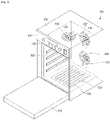
- FIG. 1 is a perspective view of a cooking apparatus 100 according to an embodiment
- FIG. 2 is a cross-sectional view of the cooking apparatus 100 according to an embodiment
- FIG. 3 is a view illustrating a case in which a steam supplier 140 is applied to the rear side of the cooking apparatus 100 according to an embodiment
- FIG. 4 is a schematic view of the steam supplier 140 according to an embodiment.
- the cooking apparatus 100 includes a main body 104 configured to form an outer appearance and provided with a cooking compartment 102 therein, a cover 106 configured to cover an upper side, both lateral sides, and a rear side of the main body 104, a convection heater 108 and a convection fan 110 disposed on the upper side and the rear side to heat the cooking compartment 102, a steam supplier 140 configured to generate steam and supply the steam to the inside of the cooking compartment 102, and a bottom heater 120 configured to additionally supply steam by heating water supplied to a bottom surface 105 of the cooking compartment 102.
- the front side of the main body 104 is opened to allow food to be put into or withdrawn from the cooking compartment 102, and the cooking compartment 102 in which the food is placed is opened or closed by a door 103 coupled to the front side of the main body 104.
- a control panel 130 provided with various operation switches for controlling the operation of the cooking apparatus 100 by a user is disposed on the upper portion of the front surface of the main body 104.
- the convection heaters 108 disposed on the upper and rear sides of the main body 104 provide heat for heating the foods inside the cooking compartment 102.
- the convection fans 110 allow the heat, which is generated by the convection heater 108, to be convected inside the cooking compartment 102 or allow the steam, which is generated by the steam generator 144 other than the convection heater 108, to be evenly circulated inside the cooking compartment 102.
- the steam supplier 140 may be provided in a space between the main body 104 and the cover 106.
- the steam supplier 140 includes a storage container 141, a water supply pump 142, a drain pump 143, a steam generator 144, and a water level sensor 145.
- the storage container 141 configured to store water, which is to be supplied to the steam supplier 140, the water supply pump 142 configured to supply water, which is supplied from the storage container 141, to the steam generator 144, and the drain pump 143 configured to discharge water, which is remaining inside the steam generator 144, to the storage container 141 may be disposed in the space between the upper portion of the main body 104 and the cover 106.
- the water supply pump 142 and the drain pump 143 are provided at a position higher than the storage container 141 with respect to the bottom surface 105 of the cooking compartment 102.
- One end of the storage container 141 is connected to one end of the water supply pump 142 and the drain pump 143 by a first connection pipe P1.
- the other end of the water supply pump 142 and the drain pump 143 is connected to one end of the steam generator 144 by a second connection pipe P2.
- the steam generator 144 heating water supplied from the storage container 141 to generate steam so as to supply the steam to the inside of the cooking compartment 102, and the water level sensor 145 being connected to the steam generator 144 so as to measure a level of water stored inside the steam generator 144 may be disposed in the space between the rear portion of the main body 104 and the cover 106.
- the steam generator 144 and the water level sensor 145 are connected by a third connection pipe P3.
- the third connection pipe P3 connects the steam generator 144 to the water level sensor 145 so that the water flows into the steam generator 144 and at the same time the water flows into the water level sensor 145.
- the steam generator 144 includes a steam container 144a generating steam and a steam heater 144b heating the water supplied to the steam container 144a.
- the steam generated in the steam generator 144 is supplied to the inside of the cooking compartment 102 through a steam supply pipe P4 connecting the steam generator 144 to the inside of the cooking compartment 102.
- the water level sensor 145 is configured to measure the level of water stored inside the steam generator 144. It is an aspect of the present disclosure to provide a control method of a cooking apparatus capable of controlling the amount of steam generated inside the cooking compartment 102 and thus it is required to measure an amount of water supplied to the steam generator 144. Therefore, according to the disclosure, the water supplied to the steam generator 144 is simultaneously supplied to the water level sensor 145 through the third connection pipe P3 by connecting the steam generator 144 to the water level sensor 145. An air outflow pipe P5 is provided at an upper portion of the water level sensor 145 to adjust a pressure difference, which is generated in the water level sensor 145 by water flowing into and out of the water level sensor 145, and the air outflow pipe P5 is connected to the outside of the cooking apparatus 100.
- the water level sensor 145 may be a float-less switch.
- the float-less switch may be configured to detect the water level by sensing the short such that a plurality of electrodes is installed in the water bath and the electrode is short according to the height of the liquid surface.
- the type of the water level sensor 145 is not limited thereto, but for convenience of description, the case of using the float-less-switch will be described as an example.
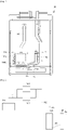
- FIG. 5 is a diagram illustrating a structure of a float-less switch.
- the float-less switch includes a sensor housing 146 and a first electrode E1 and a second electrode E2 housed within the sensor housing 146.
- the first electrode E1 is longer than the second electrode E2 in the longitudinal direction of the sensor housing 146 and thus the first electrode E1 and the second electrode E2 are installed such that the first electrode E1 is always immersed in water and a predetermined voltage is supplied to the second electrode E2.
- the end of the second electrode E2 is immersed in water.
- the current may flow through the water, and the float-less switch may detect the water level by sensing the current flow.
- the number of float-less switch electrodes may vary. As the number of float-less switch electrodes increases, the water level may be detected more precisely.
- the bottom heater 120 configured to additionally generate steam by heating the water supplied into the cooking compartment 102 is disposed on the bottom surface 105 of the cooking compartment 102. According to the disclosure, it may be possible to additionally generate steam using the bottom heater 120 installed on the bottom surface 105 of the cooking compartment 102, so as to secure the cooking performance of the cooking apparatus 100 without increasing the output of the steam generator 144. Hereinafter, it will be described in detail in the related part.
- FIG. 6 is a view illustrating a control block diagram of the cooking apparatus 100 according to an embodiment.
- the cooking apparatus 100 includes the control panel 130, the water level sensor 145, the memory 150, the drain pump 143, the water supply pump 142, the steam heater 144b, the bottom heater 120, and the controller 160.
- the redundant description of the drain pump 143, the water supply pump 142, the steam heater 144b, and the bottom heater 120 will be omitted.
- the control panel 130 receives an operation command of the cooking apparatus 100 from a user and displays operation information of the cooking apparatus 100 to the user.
- the control panel 130 includes an input configured to receive an operation command of a user, and a display configured to display the operation information of the cooking apparatus 100.
- the input may receive an operation mode setting command for the cooking apparatus 100. According to the disclosure, it may be possible to set an operation mode of the cooking apparatus 100 so as to regulate the amount of steam supplied to the cooking compartment 102 in stages.
- the operation mode of the cooking apparatus 100 may be classified into a first cooking mode and a second cooking mode.
- the first cooking mode is defined as a cooking mode by using steam generated by the steam generator 144
- the second cooking mode is defined as a cooking mode by using steam, which is generated in the bottom surface 105 of the cooking compartment 102 by additionally supplying water into the cooking compartment 102 and at the same time by using steam generated by the steam generator 144.
- the second cooking mode may be classified into sub-modes based on the amount of steam, and hereinafter for convenience of description, a case in which an operation mode of the cooking apparatus 100 is classified into the first and second mode will be described as an example.
- the display may display an operation mode of the cooking apparatus 100 and provide a visual image of the corresponding mode.
- the input may employ a pressure switch or a touch pad and the display may employ a liquid crystal display (LED) panel or a light emitting diode (LED) panel.
- LED liquid crystal display
- LED light emitting diode
- the water level sensor 145 may detect the level of the water supplied to the steam generator 144 and transmit the detected water level information to the controller 160.
- a float-less switch may be used as the water level sensor 145.
- the memory 150 may store various data, programs or applications for driving and controlling the cooking apparatus 100.
- the memory 150 may store water level information, water supply amount and water supply time information, and drain time information, wherein the water is to be supplied to the steam generator 144 according to the operation mode of the cooking apparatus 100, and operation time information of the bottom heater 120.
- the memory 150 may store water level information, water supply amount and water supply time information, and drain time information, wherein the information is related to target steam amount to be supplied to the steam generator 144, and operation time information of the bottom heater 120.
- the memory 150 may store the water level information of the steam generator 144 detected by the water level sensor 145.
- the memory 150 may be a concept including a ROM and a RAM of a controller 160, which will be described later.
- the memory 150 may be used as a term including a memory card (for example, micro SD card, USB memory, etc.) mounted on the cooking apparatus 100 according to embodiments.
- the memory 150 may include a nonvolatile memory, a volatile memory, a hard disk drive (HDD) or a solid state drive (SSD).
- the controller 160 may include a processor, a ROM in which a control program is stored for controlling the control of the cooking apparatus 100, and a RAM in which a signal and data input from the outside of the cooking apparatus 100 are stored or the RAM, which is used as a storage area corresponding to various operation performed in the cooking apparatus 100.
- the controller 160 may control the overall operation of the cooking apparatus 100 and the signal flow between the internal components of the cooking apparatus 100, and perform data processing.
- the controller 160 may execute a program or various applications stored in the memory 150 when the input of the user or a predetermined condition is satisfied.
- the controller 160 may execute the water leakage prevention program of the water supply pump 142.
- the water leakage prevention program described later may be applied to a process of controlling the operation of the water supply pump 142 in the cooking mode of the cooking apparatus 100 according to the disclosure.
- Siphon means a device provided with an inverted 'U' shaped tube and configured to allow water in one place to flow to another place lower than the one place by passing through another place higher than the one place. Since water in the tube flows due to the pressure difference, water may flow over although there is a high place in the middle. When the high place in the middle exceeds hydraulic grade line, a pressure in the tube may become a negative. However, since the absolute pressure cannot be lower than 0 (zero), the water may not flow continuously when the tube is raised above the level corresponding to atmospheric pressure from the hydrodynamic inclined line.
- the drain pump 143 is operated at the last stage of the water supply process, so as to prevent the water leakage. Accordingly, it may be possible to prevent the water leakage although the pump motor of the water supply pump 142 fails.
- FIG. 7 is a view illustrating a water supply process of the cooking apparatus 100 according to the disclosure
- FIG. 8 is a view illustrating a water drainage process of the cooking apparatus 100 according to the disclosure.
- the controller 160 controls the operation of the water supply pump 142 so as to supply water to the steam generator 144 from the storage container 141. As illustrated in FIG. 7 , the water is supplied from the storage container 141 to the steam generator 144 as the water supply pump 142 operates. Until the level of water supplied to the steam generator 144 reaches a predetermined first position, the controller 160 controls the operation of the water supply pump 142 based on sensor value information transmitted from the water level sensor 145.
- the controller 160 allows the operation of the water supply pump 142 to be stopped.
- the water may be unintentionally supplied from the storage container 141 to the steam generator 144 due to the above-described siphon principle.
- a control process of the operation of the drain pump 143 described below is performed, so as to prevent the water leakage.
- the controller 160 controls the operation of the drain pump 143 to discharge the water present in the steam generator 144. As illustrated in FIG. 8 , the water is discharged from the steam generator 144 to the storage container 141 as the drain pump 143 operates.
- the controller 160 may control the operation of the drain pump 143 for a first predetermined period of time, so as to discharge water present in the steam generator 144.
- the first period of time may be designed by the designer's intention and thus the first period of time may be designed as a proper period of time in a target range for changing a water flow into an opposite direction so as to prevent the water leakage in the water supply process.
- the controller 160 may control the operation of the drain pump 143 for a predetermined period of time after the water supply process. According to embodiments, the controller 160 may control the operation of the drain pump 143 by receiving sensor value information related to the plurality of positions, from the water level sensor 145.
- the controller 160 may performs a program for increasing the steam generation amount so as to increase the steam generation amount according to the cooking mode of the cooking apparatus 100.
- the controller 160 may perform the control operation for increasing the steam generation amount according to the cooking mode of the cooking apparatus 100, and hereinafter the control process of the controller 160 will be described in detail.
- the controller 160 may control the operation of the water supply pump 142 to supply water to the steam generator 144 when an operation command related to the first cooking mode is input from the user.
- the controller 160 may control the operation of the steam heater 144b installed in the steam generator 144 to generate steam.
- supplying water to the steam container 144a of the steam generator 144 may be described as supplying water to the steam generator 144.
- the steam generated by the steam generator 144 is supplied to the inside of the cooking compartment 102 by passing through the steam supply pipe P4.
- the controller 160 may identify whether the level of the water supplied to the steam generator 144 reaches the third position, based on the sensor value information received from the second electrode E2 of the water level sensor 145. When the level of the water present in the water level sensor 145 gradually increases and the level of the water reaches the third position, a sensor value of the second electrode E2 may be changed from v 1 V to 0 V. The controller 160 may identify a point of time, in which the sensor value of the second electrode E2 is changed from v 1 V to 0 V, as a point of time in which the level of water present in the steam generator 144 reaches the third position.
- the controller 160 may output an operation control command to the steam heater 144b.
- the controller 160 may control the operation of the water supply pump 142 to supply water to the steam generator 144.
- the controller 160 may control the water supply pump 142 for the third predetermined period of time, so as to additionally supply water to the steam generator 144.
- the third period of time corresponds to a value that is predetermined according to the specification of the cooking apparatus 100 by the designer, wherein the third period of time corresponds to a sufficient period of time to allow water, which flows over after being supplied to the inside of the steam generator 144, to be supplied to the inside of the cooking compartment 102 by passing through the steam supply pipe P4.
- the third period of time may vary according to the size of the steam container 144a installed inside the steam generator 144 and the capacity of the water supply pump 142.
- the above mentioned operation is configured to supply water to the inside of the cooking compartment 102 through the steam supply pipe P4 connecting the steam generator 144 to the inside of the cooking compartment 102.
- the water supplied to the inside of the cooking compartment 102 may be collected on the bottom surface 105 of the cooking compartment 102 and thus when the bottom heater 120 installed on the bottom surface 105 of the cooking compartment 102 operates, steam generated in the bottom surface 105 of the cooking compartment 102 may be supplied to the cooking process.
- the controller 160 may control the operation of the steam generator 144 to discharge water from the steam generator 144.
- the drain pump 143 operates, the water is discharged from the steam generator 144, and the level of water gradually decreases.
- the controller 160 may control the operation of the drain pump 143.
- a sensor value of the second electrode E2 may be changed from 0 V to v 1 V.
- the controller 160 may identify a point of time, in which the sensor value of the second electrode E2 is changed from 0 V to v 1 V, as a point of time in which the level of water present in the steam generator 144 reaches the third position.
- the controller 160 may control the operation of the steam heater 144b installed on the steam generator 144 and the operation of the bottom heater 120 installed on the bottom surface 105 of the cooking compartment 102.
- the controller 160 may control the operation of the steam heater 144b and the bottom heater 120 for a fourth predetermined period of time.
- the fourth predetermined period of time may be related to the third period of time corresponding to a period of time for additionally supplying water to the steam generator 144. That is, as the amount of water supplied to the bottom surface 105 of the cooking compartment 102 increases, the operation time of the heater may be set longer.
- the operation time of the steam heater 144b may be set to be identical to the operation time of the bottom heater 120, but is not limited thereto. Therefore, the operation time of the steam heater 144b may be set to be longer than the operation time of the bottom heater 120 or alternatively, the operation time of the bottom heater 120 may be set to be longer than the operation time of the steam heater 144b.
- the setting of the operation time may be related to the amount of water supplied to the bottom surface 105 of the cooking compartment 102.
- the controller 160 may control the operation of the drain pump 143 to discharge water from the steam generator 144.
- the controller 160 may terminate the cooking mode.
- the controller 160 may identify that the discharging operation is completed after controlling the operation of the drain pump 143 for a predetermined period of time. According to embodiments, the controller 160 may identify whether the discharging operation is completed based on the sensor value information collected by the water level sensor 145.
- the cooking apparatus 100 is configured to additionally supply steam to the inside of the cooking compartment 102 using the bottom heater 120 installed on the bottom surface 105 of the cooking apparatus 100, and thus without increasing the output of the steam generator 144, it may be possible to improve the steam cooking performance of the cooking apparatus 100 by increasing the total amount of steam.
- the above mentioned control for increasing the amount of steam and the water leakage prevention control may be selectively applied, as needed or both of the control for increasing the amount of steam and the water leakage prevention control may be applied to the cooking apparatus 100 according to embodiments.
- FIG. 9 is a view illustrating a control process of a cooking apparatus 100 according to another embodiment
- FIG. 10 is a view illustrating a change in the level of water supplied to the water level sensor 145 according to the control process shown in FIG. 9 . Since the water supplied to the steam container 144a of the steam generator 144 is supplied to the water level sensor 145 at the same level, a view illustrating a change in the level of the water supplied to the steam container 144a is omitted in FIG. 10 .
- a water supply process is started by a process of controlling the operation of the water supply pump 142.
- the controller 160 controls the operation of the water supply pump 142 to supply water from the storage container 141 to the steam generator 144.
- the water is supplied from the storage container 141 to the steam generator 144 as the water supply pump 142 operates (300).
- the controller 160 controls the operation of the water supply pump 142 based on the sensor value information transmitted from the water level sensor 145 (305).
- the controller 160 may control the operation of the water supply pump 142 until the level of the water supplied to the steam generator 144 reaches the first predetermined position D1 (300 and 305).
- the controller 160 allows the water supply pump 142 to be stopped (305 and 310).
- the controller 160 controls the operation of the drain pump 143 to discharge the water present in the steam generator 144 (315).
- the controller 160 may control the operation of the drain pump 143 for a first predetermined period of time T1 (320). This control process is to change the water flow into the opposite direction to prevent the water leakage during the water supply process.
- the controller 160 may stop the drain pump 143 and terminate the water supply process when the first period of time T1 is expired (325).
- FIG. 11 is a view illustrating a control process of a cooking apparatus 100 according to another embodiment
- FIG. 12 is a view illustrating a change in the level of water supplied to a water level sensor 145 according to the control process shown in FIG. 11 . Since the water supplied to a steam container 144a of a steam generator 144 is supplied to the water level sensor 145 at the same level, a view illustrating a change in the level of the water supplied to the steam container 144a is omitted in FIG. 12 .
- a water supply process is started by a process of controlling the operation of the water supply pump 142.
- the controller 160 may control the operation of the water supply pump 142 to supply water from the storage container 141 to the steam generator 144.
- the water is supplied from the storage container 141 to the steam generator 144 as the water supply pump 142 operates (300).
- the controller 160 may control the operation of the water supply pump 142 based on the sensor value information transmitted from the water level sensor 145 (305).
- the controller 160 may control the water supply pump 142 to additionally supply water to the steam generator 144 (330).
- the controller 160 may control the operation of the water supply pump 142 for a second predetermined period of time T2 (335).
- the controller 160 may stop the operation of the water supply pump 142 and control the operation of the drain pump 143 to discharge the water in the steam generator 144 (335 and 310).
- the controller 160 may control the operation of the drain pump 143 so that the level of water in the steam generator 144 reaches the first position D1 again (315 and 340). This control process is to change the water flow into the opposite direction to prevent the water leakage during the water supply process.
- the controller 160 may stop the drain pump 143 and terminate the water supply process when the level of water in the steam generator 144 reaches the first position D1 (340 and 325).
- FIG. 13 is a view illustrating a control process of a cooking apparatus 100 according to another embodiment
- FIG. 14 is a view illustrating a change in the level of water supplied to a water level sensor 145 according to the control process shown in FIG. 13 . Since the water supplied to a steam container 144a of a steam generator 144 is supplied to the water level sensor 145 at the same level, a view illustrating a change in the level of the water supplied to the steam container 144a is omitted in FIG. 14 .
- a control process as illustrated in FIGS. 13 and 14 is performed by controlling an operation of the water supply pump 142 and the drain pump 143 based on the sensor value information of the water level sensor 145.
- the second electrode E2 is the shortest electrode.
- the third electrode E3 is longer than the second electrode E2 and shorter than the first electrode E1.
- the first electrode E1 is the longest ground electrode and thus always immersed in water.
- a water supply process is started by a process of controlling the operation of the water supply pump 142.
- the controller 160 may control the operation of the water supply pump 142 to supply water from the storage container 141 to the steam generator 144 (300). As the water supply pump 142 operates, the water is supplied from the storage container 141 to the steam generator 144 through a first and second connection pipe P1 and P2.
- the controller 160 may control the operation of the water supply pump 142 based on the sensor value information transmitted from the water level sensor 145 (305).
- the controller 160 may control the operation of the water supply pump 142 based on the sensor value information transmitted from the second electrode E2 of the water level sensor 145.
- the level of the water present in the water level sensor 145 gradually increases as the water is supplied to the steam generator 144. Therefore, when the level of the water reaches the first position D1, a sensor value of the second electrode E2 may be changed from v 2 V to 0 V.
- the controller 160 may identify a point of time, in which the sensor value of the second electrode E2 is changed from v 2 V to 0 V, as a point of time in which the level of water present in the steam generator 144 reaches the first position D1.
- the controller 160 may stop the operation of the water supply pump 142 and control the drain pump 143 (305 and 310).
- the level of water present in the steam container 144a of the steam generator 144 decreases as the drain pump 143 operates, and thus the water level of the water level sensor 145 gradually decreases (315).
- the controller 160 may control the operation of the drain pump 143 based on the sensor value information transmitted from the third electrode E3 of the water level sensor 145.
- a sensor value of the third electrode E3 may be changed from 0 V to v 3 V.
- the controller 160 may identify a point of time, in which the sensor value of the third electrode E3 is changed from 0 V to v 3 V, as a point of time in which the level of water present in the steam generator 144 reaches the second position D2. This control process is to change the water flow into the opposite direction to prevent water leakage during the water supply process.
- the controller 160 may stop the drain pump 143 and terminate the water supply process, when the level of water in the steam generator 144 reaches the predetermined second position D2 (345 and 325).
- FIG. 15 is a view illustrating a control process of the cooking apparatus 100 according to an embodiment
- FIG. 16 is a view illustrating a change in the level of water supplied to the water level sensor 145 according to the control process shown in FIG. 15 . Since the water supplied to a steam container 144a of a steam generator 144 is supplied to the water level sensor 145 at the same level, a view illustrating a change in the level of the water supplied to the steam container 144a is omitted in FIG. 15 .
- the controller 160 may control the operation of the water supply pump 142 to supply water to the steam generator 144 when an operation command for the second cooking mode is input from the user (200).
- the controller 160 may control the operation of the water supply pump 142 based on the sensor value information transmitted from the water level sensor 145 (205).
- the controller 160 may identify whether the level of the water supplied to the steam generator 144 reaches the third position D3 based on the sensor value information transmitted from the second electrode E2 of the water level sensor 145.
- redundant description will be omitted.
- the controller 160 may control the operation of the water supply pump 142 for the third predetermined period of time T3, so as to additionally supply water to the steam generator 144 (205, 210 and 215).
- This operation is for supplying water into the cooking compartment 102 through the steam supply pipe P4 connecting the steam generator 144 to the inside of the cooking compartment 102.
- the third period of time T3 is set as an appropriate period of time to allow the water supplied to the steam generator 144 to be supplied to the inside of the cooking compartment 102 through the steam supply pipe P4.
- Water exceeding the capacity of the steam container 144a is supplied so that the water supplied to the steam generator 144 is supplied to the inside of the cooking compartment 102. Therefore, the water supplied to the water level sensor 145 may fill up the inside of the sensor housing 146 of the water level sensor 145 as illustrated in FIG. 16 .
- the water supplied into the cooking compartment 102 is collected on the bottom surface 105 of the cooking compartment 102 and when the bottom heater 120 installed on the bottom surface 105 of the cooking compartment 102 operates, steam generated in the bottom surface 105 of the cooking compartment 102 may be provided to the cooking process. Therefore, it may be possible to increase the steam generation amount in the cooking mode.
- the controller 160 may control the operation of the drain pump 143 to discharge the water from the steam generator 144 when the third period of time T3 is expired.
- the drain pump 143 operates, the water is discharged from the steam generator 144, and the level of the water supplied to the water level sensor 145 gradually decreases (215 and 220).
- the controller 160 may control the operation of the drain pump 143 until the level of water in the steam generator 144 reaches the third position D3.
- the controller 160 may simultaneously control the operation of the steam heater 144b installed on the steam generator 144 and the operation of the bottom heater 120 installed on the bottom surface 105 of the cooking compartment 102 (225 and 230).
- the controller 160 may control the operation of the steam heater 144b and the operation of the bottom heater 120 for a fourth predetermined period of time T4.
- An operation control time of the steam heater 144b and the bottom heater 120 may be the same or different from each other and hereinafter redundant description will be omitted.
- the controller 160 may control the operation of the drain pump 143 to discharge the water from the steam generator 144 when the fourth period of time T4 is expired. When the discharging operation is completed, the controller 160 may terminate the cooking mode (235 and 240).
Landscapes
- Engineering & Computer Science (AREA)
- Chemical & Material Sciences (AREA)
- Mechanical Engineering (AREA)
- General Engineering & Computer Science (AREA)
- Combustion & Propulsion (AREA)
- Food Science & Technology (AREA)
- Life Sciences & Earth Sciences (AREA)
- Nutrition Science (AREA)
- Health & Medical Sciences (AREA)
- Polymers & Plastics (AREA)
- Cookers (AREA)
- Physics & Mathematics (AREA)
- Thermal Sciences (AREA)
- Sustainable Development (AREA)
- Sustainable Energy (AREA)
- Commercial Cooking Devices (AREA)
- General Preparation And Processing Of Foods (AREA)
Claims (8)
- Steuerverfahren für ein Kochgerät, das mit einem zum Speichern von Wasser konfigurierten Speicherbehälter (141), einem unterhalb des Speicherbehälters installierten Dampfgenerator (144) zum Aufnehmen des Wassers aus dem Speicherbehälter, einer oberhalb des Speicherbehälters installierten Wasserzufuhrpumpe (142) zum Zuführen des Wassers aus dem Speicherbehälter an den Dampfgenerator und einer oberhalb des Speicherbehälters installierten Ablaufpumpe (143) zum Ablassen des Wassers aus dem Dampfgenerator in den Speicherbehälter versehen ist, wobei das Steuerverfahren umfasst:Steuern eines Betriebs der Wasserzufuhrpumpe, um das Wasser aus dem Vorratsbehälter dem Dampfgenerator zuzuführen; undSteuern eines Betriebs der Ablaufpumpe, um Wasser in dem Dampfgenerator abzulassen, wenn ein Pegel von dem Dampfgenerator zugeführtem Wasser eine erste Position (D1) erreicht, nachdem der Betrieb der Wasserzufuhrpumpe gestoppt wurde.
- Steuerverfahren nach Anspruch 1, wobei das Kochgerät ferner einen Wasserstandssensor (145) umfasst, der zum Sammeln von Wasserstandsinformationen bezüglich des Wassers in dem Dampfgenerator konfiguriert ist, und
wobei das Steuerverfahren ferner das Sammeln, durch den Wasserstandssensor, von Wasserstandsinformationen bezüglich des dem Dampfgenerator zugeführten Wassers umfasst. - Steuerverfahren nach Anspruch 1, wobei das Steuern des Betriebs der Ablaufpumpe das Steuern der Ablaufpumpe für eine erste Zeitspanne (T1) umfasst, um Wasser in dem Dampfgenerator abzulassen.
- Steuerverfahren nach Anspruch 1, ferner umfassend das Steuern der Wasserzufuhrpumpe, um dem Dampfgenerator zusätzlich Wasser zuzuführen, wenn der Pegel von dem Dampfgenerator zugeführtem Wasser die erste Position erreicht.
- Steuerverfahren nach Anspruch 4, ferner umfassend das Steuern der Wasserzufuhrpumpe für eine zweite Zeitspanne (T2).
- Steuerverfahren nach Anspruch 5, ferner umfassend das Steuern des Betriebs der Ablaufpumpe, um Wasser in dem Dampfgenerator abzulassen, wenn die zweite Zeitspanne abgelaufen ist.
- Steuerverfahren nach Anspruch 6, wobei das Steuern des Betriebs der Ablaufpumpe, um das Wasser in dem Dampfgenerator abzulassen, das Steuern des Betriebs der Ablaufpumpe umfasst, um zu ermöglichen, dass der Pegel von dem Dampfgenerator zugeführtem Wasser wieder die erste Position erreicht.
- Steuerverfahren nach Anspruch 1, wobei das Steuern des Betriebs der Ablaufpumpe, um das Wasser in dem Dampfgenerator abzulassen, das Steuern des Betriebs der Ablaufpumpe umfasst, um zu ermöglichen, dass der Pegel von dem Dampfgenerator zugeführtem Wasser eine zweite Position (D2) erreicht.
Priority Applications (1)
| Application Number | Priority Date | Filing Date | Title |
|---|---|---|---|
| EP22173517.8A EP4063739B1 (de) | 2017-05-19 | 2018-05-18 | Steuerverfahren für eine kochvorrichtung |
Applications Claiming Priority (2)
| Application Number | Priority Date | Filing Date | Title |
|---|---|---|---|
| KR1020170062354A KR102357903B1 (ko) | 2017-05-19 | 2017-05-19 | 조리기기의 제어 방법 |
| PCT/KR2018/005728 WO2018212623A1 (en) | 2017-05-19 | 2018-05-18 | Control method of cooking apparatus |
Related Child Applications (2)
| Application Number | Title | Priority Date | Filing Date |
|---|---|---|---|
| EP22173517.8A Division-Into EP4063739B1 (de) | 2017-05-19 | 2018-05-18 | Steuerverfahren für eine kochvorrichtung |
| EP22173517.8A Division EP4063739B1 (de) | 2017-05-19 | 2018-05-18 | Steuerverfahren für eine kochvorrichtung |
Publications (3)
| Publication Number | Publication Date |
|---|---|
| EP3615867A1 EP3615867A1 (de) | 2020-03-04 |
| EP3615867A4 EP3615867A4 (de) | 2020-08-05 |
| EP3615867B1 true EP3615867B1 (de) | 2022-06-29 |
Family
ID=64270099
Family Applications (2)
| Application Number | Title | Priority Date | Filing Date |
|---|---|---|---|
| EP18802940.9A Active EP3615867B1 (de) | 2017-05-19 | 2018-05-18 | Steuerverfahren für eine kochvorrichtung |
| EP22173517.8A Active EP4063739B1 (de) | 2017-05-19 | 2018-05-18 | Steuerverfahren für eine kochvorrichtung |
Family Applications After (1)
| Application Number | Title | Priority Date | Filing Date |
|---|---|---|---|
| EP22173517.8A Active EP4063739B1 (de) | 2017-05-19 | 2018-05-18 | Steuerverfahren für eine kochvorrichtung |
Country Status (5)
| Country | Link |
|---|---|
| US (2) | US11141017B2 (de) |
| EP (2) | EP3615867B1 (de) |
| KR (3) | KR102357903B1 (de) |
| CN (1) | CN110914598A (de) |
| WO (1) | WO2018212623A1 (de) |
Families Citing this family (16)
| Publication number | Priority date | Publication date | Assignee | Title |
|---|---|---|---|---|
| CN110200516A (zh) | 2017-08-09 | 2019-09-06 | 沙克忍者运营有限责任公司 | 烹饪系统 |
| KR102455063B1 (ko) * | 2018-04-04 | 2022-10-14 | 엘지전자 주식회사 | 조리기기 및 그의 제어방법 |
| KR102126485B1 (ko) * | 2018-10-23 | 2020-06-24 | 엘지전자 주식회사 | 스팀 공급 장치가 구비된 전자 조리 기기 |
| CN111258342B (zh) * | 2018-11-30 | 2022-01-25 | 宁波方太厨具有限公司 | 一种蒸箱的电极水位控制方法 |
| KR102133286B1 (ko) * | 2018-12-14 | 2020-07-13 | 엘지전자 주식회사 | 조리실의 자동 세척이 가능한 전자 조리 기기 |
| DE102019201462A1 (de) * | 2019-02-05 | 2020-08-06 | BSH Hausgeräte GmbH | Gargerät mit einer Dampferzeugungsvorrichtung, die eine Regulierungseinrichtung mit zumindest einem Schwimmerventil aufweist, sowie Verfahren zum Betreiben einer Dampferzeugungsvorrichtung |
| WO2020176477A1 (en) | 2019-02-25 | 2020-09-03 | Sharkninja Operating Llc | Cooking system with guard |
| US11033146B2 (en) | 2019-02-25 | 2021-06-15 | Sharkninja Operating Llc | Cooking device and components thereof |
| DE102019110381A1 (de) * | 2019-04-18 | 2020-10-22 | Rational Aktiengesellschaft | Verfahren zum Ermitteln eines Füllstandes eines Wassertanks und Gargerät |
| US11647861B2 (en) | 2020-03-30 | 2023-05-16 | Sharkninja Operating Llc | Cooking device and components thereof |
| CN113028458B (zh) * | 2021-03-02 | 2024-05-07 | 中山百得厨卫有限公司 | 一种集成灶的加水控制方法及装置 |
| AU2022367359A1 (en) * | 2021-10-15 | 2024-05-23 | Electrolux Professional, Inc. | Steamer system and method |
| USD1041233S1 (en) | 2021-10-15 | 2024-09-10 | Electrolux Professional, Inc. | Steam cooker appliance |
| USD1104595S1 (en) * | 2023-06-09 | 2025-12-09 | Duke Manufacturing Co. | Food holding cabinet |
| CN116965687A (zh) * | 2023-09-04 | 2023-10-31 | 珠海格力电器股份有限公司 | 一种蒸汽发生器的加水控制方法及烹饪器具 |
| USD1083480S1 (en) * | 2023-12-08 | 2025-07-15 | Shenzhen Tingzhida Technology Co., LTD | Food dehydrator |
Family Cites Families (55)
| Publication number | Priority date | Publication date | Assignee | Title |
|---|---|---|---|---|
| US4287407A (en) * | 1978-08-17 | 1981-09-01 | Hobart Corporation | Tank flushing delay arrangement for a steam generator |
| US4186419A (en) * | 1978-11-20 | 1980-01-29 | Sims Bobby H | Apparatus for monitoring and controlling liquid level |
| US4409999A (en) * | 1981-08-07 | 1983-10-18 | Pedziwiatr Edward A | Automatic ultrasonic cleaning apparatus |
| FR2660733A1 (fr) * | 1990-04-04 | 1991-10-11 | Bourgeois Ste Coop Production | Generateur de vapeur d'eau pour appareil de cuisson, muni d'un dispositif de vidange. |
| FR2711229B1 (fr) * | 1993-10-12 | 1995-12-08 | Bourgeois Ste Coop Prod | Four à vapeur muni d'un dispositif d'évacuation de la vapeur. |
| JP2741344B2 (ja) * | 1994-07-22 | 1998-04-15 | 大同メタル工業株式会社 | 超音波処理装置 |
| US5549038A (en) * | 1995-11-16 | 1996-08-27 | Market Forge Industries | Modulated steam cooker |
| US6078729A (en) * | 1997-10-21 | 2000-06-20 | National Environmental Products Ltd., Inc. | Foam, drain and fill control system for humidifier |
| IT1304664B1 (it) * | 1998-09-30 | 2001-03-28 | Merloni Elettrodomestici Spa | Sistema per la programmazione di un apparato elettrodomestico acontrollo elettronico. |
| US6227215B1 (en) * | 1999-02-23 | 2001-05-08 | Yasumasa Akazawa | Piping cleaning device |
| US20030079735A1 (en) * | 2001-10-25 | 2003-05-01 | Hines Robert S. | Baking oven construction |
| US6833032B1 (en) * | 2002-11-05 | 2004-12-21 | Blodgett Holdings, Inc. | Automatic deliming process |
| DE10259829B4 (de) * | 2002-12-19 | 2005-10-06 | Convotherm Elektrogeräte GmbH | Verfahren zum Entkalken von Dampferzeugern für Gargeräte |
| JP3795050B2 (ja) | 2004-03-22 | 2006-07-12 | シャープ株式会社 | 蒸気調理器 |
| KR101132331B1 (ko) * | 2004-07-14 | 2012-04-05 | 삼성전자주식회사 | 가열조리장치 및 그 제어방법 |
| US20060249137A1 (en) * | 2005-05-03 | 2006-11-09 | Malcolm Reay | System and method for draining water from a steam oven |
| US7537004B2 (en) * | 2005-05-03 | 2009-05-26 | Whirlpool Corporation | Steam oven with fluid supply and drain vessel |
| JP3868464B1 (ja) * | 2005-07-26 | 2007-01-17 | シャープ株式会社 | 加熱調理器 |
| US20070114222A1 (en) * | 2005-11-24 | 2007-05-24 | Samsung Electronics Co., Ltd. | Steam cooking apparatus |
| US7918235B2 (en) * | 2005-12-19 | 2011-04-05 | Jeffery Ohler | Steam generator auto—blow down and scale reduction system |
| US7348520B2 (en) * | 2006-03-20 | 2008-03-25 | Ching-Hsiang Wang | Oven with a heat circulating device |
| US20080006261A1 (en) * | 2006-07-06 | 2008-01-10 | Atul Saksena | Steam generator with external probe housing unit |
| US20090250452A1 (en) * | 2006-08-08 | 2009-10-08 | Sze-Man Tse | Steam Convection Oven |
| KR100802019B1 (ko) * | 2006-09-27 | 2008-02-12 | 삼성전자주식회사 | 스팀발생장치 및 이를 갖는 가열조리장치 |
| KR101041079B1 (ko) * | 2006-09-28 | 2011-06-13 | 삼성전자주식회사 | 수위감지유닛과 이를 갖는 스팀발생장치 및 그스팀발생장치를 갖는 가열조리장치 |
| KR20080065134A (ko) | 2007-01-08 | 2008-07-11 | 삼성전자주식회사 | 수위센서와 이를 갖는 스팀발생기 및 그 스팀발생기를 갖는조리장치와 그 제어방법 |
| KR101059818B1 (ko) * | 2007-01-08 | 2011-08-26 | 삼성전자주식회사 | 스팀발생기와 이를 갖는 조리장치 및 그 제어방법 |
| US7623771B2 (en) * | 2007-06-25 | 2009-11-24 | Honeywell International Inc. | Detection of deposits in steam humidifiers |
| US7690062B2 (en) * | 2007-08-31 | 2010-04-06 | Whirlpool Corporation | Method for cleaning a steam generator |
| US8080766B2 (en) * | 2007-10-26 | 2011-12-20 | Premark Feg L.L.C. | Steam oven system with steam generator |
| KR101428810B1 (ko) | 2007-12-03 | 2014-08-08 | 엘지전자 주식회사 | 오븐 |
| JP2010032120A (ja) * | 2008-07-29 | 2010-02-12 | Sharp Corp | 蒸気発生装置および加熱調理器 |
| KR20110058144A (ko) | 2009-11-25 | 2011-06-01 | 주식회사 대우일렉트로닉스 | 전자레인지용 스팀공급장치 및 그 제어방법 |
| DE102009055146A1 (de) * | 2009-12-22 | 2011-06-30 | BSH Bosch und Siemens Hausgeräte GmbH, 81739 | Dampferzeugungssystem für ein Haushaltsgerät und Verfahren zum Betreiben eines Dampferzeugungssystems |
| KR101668457B1 (ko) | 2010-01-12 | 2016-10-24 | 동부대우전자 주식회사 | 전자레인지 |
| FR2958725B1 (fr) | 2010-04-09 | 2014-02-28 | Fagorbrandt Sas | Four de cuisson comprenant un panneau de commande pourvu d'au moins un moyen de selection unique et procede associe. |
| FR2958724B1 (fr) | 2010-04-09 | 2012-03-16 | Fagorbrandt Sas | Four de cuisson comprenant au moins un dispositif de guidage d'une conduite de circulation d'eau entre un tiroir de remplissage d'eau et un reservoir d'eau. |
| CN102438662A (zh) * | 2010-06-18 | 2012-05-02 | 中村正一 | 清洗杀菌装置 |
| KR101827831B1 (ko) * | 2011-04-28 | 2018-02-12 | 삼성전자주식회사 | 스팀조리기기 |
| KR101931364B1 (ko) * | 2012-08-30 | 2018-12-21 | 삼성전자주식회사 | 스팀발생장치 및 이를 이용한 조리기기 |
| KR101981674B1 (ko) * | 2012-12-21 | 2019-05-24 | 삼성전자주식회사 | 조리기기 |
| JP6167333B2 (ja) * | 2013-05-08 | 2017-07-26 | パナソニックIpマネジメント株式会社 | 蒸気発生装置および加熱調理器 |
| US9375021B2 (en) * | 2013-07-29 | 2016-06-28 | Alto-Shaam, Inc. | Combination oven with reduced smoke flavor transfer |
| DE102014206281A1 (de) * | 2014-04-02 | 2015-10-08 | BSH Hausgeräte GmbH | Betreiben eines Verdampfers eines Haushaltsgeräts |
| EP3134683B1 (de) * | 2014-04-22 | 2019-01-09 | Illinois Tool Works Inc. | Ofen mit wasser-dampf-trennung und verfahren zur verwendung dieses ofens |
| CA2939528C (en) * | 2014-05-26 | 2019-01-08 | Sharp Kabushiki Kaisha | Cooking device |
| DE102014210669A1 (de) | 2014-06-05 | 2015-12-17 | BSH Hausgeräte GmbH | Verdampfer |
| KR102226003B1 (ko) * | 2014-09-02 | 2021-03-10 | 삼성전자주식회사 | 조리기기 |
| US20160061458A1 (en) * | 2014-09-02 | 2016-03-03 | B/E Aerospace, Inc. | Steam Injection System and Method |
| CN106574789B (zh) * | 2014-09-04 | 2020-04-24 | 伊莱克斯家用电器股份公司 | 带有整合的水蒸发器的家用烤箱 |
| US10478005B2 (en) * | 2014-09-05 | 2019-11-19 | Sharp Kabushiki Kaisha | Steam generating apparatus and heating cooker |
| KR102252918B1 (ko) * | 2014-11-27 | 2021-05-18 | 엘지전자 주식회사 | 스팀발생기 및 이를 포함한 조리기기 |
| CN204683356U (zh) * | 2015-05-27 | 2015-10-07 | 陈垣耀 | 一种蒸汽产生装置 |
| KR102549150B1 (ko) * | 2016-09-09 | 2023-06-30 | 삼성전자주식회사 | 조리기기 및 그 제어방법 |
| US11608988B2 (en) | 2018-04-09 | 2023-03-21 | Whirlpool Corporation | Steam generating system |
-
2017
- 2017-05-19 KR KR1020170062354A patent/KR102357903B1/ko active Active
-
2018
- 2018-05-18 EP EP18802940.9A patent/EP3615867B1/de active Active
- 2018-05-18 WO PCT/KR2018/005728 patent/WO2018212623A1/en not_active Ceased
- 2018-05-18 US US15/983,474 patent/US11141017B2/en active Active
- 2018-05-18 CN CN201880047897.XA patent/CN110914598A/zh active Pending
- 2018-05-18 EP EP22173517.8A patent/EP4063739B1/de active Active
-
2021
- 2021-09-08 US US17/469,414 patent/US12419453B2/en active Active
-
2022
- 2022-01-26 KR KR1020220011456A patent/KR102422877B1/ko active Active
- 2022-07-14 KR KR1020220086841A patent/KR102613453B1/ko active Active
Also Published As
| Publication number | Publication date |
|---|---|
| EP3615867A4 (de) | 2020-08-05 |
| KR102422877B1 (ko) | 2022-07-21 |
| EP3615867A1 (de) | 2020-03-04 |
| US11141017B2 (en) | 2021-10-12 |
| US12419453B2 (en) | 2025-09-23 |
| KR102357903B1 (ko) | 2022-02-03 |
| US20180332993A1 (en) | 2018-11-22 |
| KR20220104128A (ko) | 2022-07-26 |
| KR20220017976A (ko) | 2022-02-14 |
| KR20180127047A (ko) | 2018-11-28 |
| CN110914598A (zh) | 2020-03-24 |
| US20210401216A1 (en) | 2021-12-30 |
| KR102613453B1 (ko) | 2023-12-14 |
| EP4063739B1 (de) | 2025-11-26 |
| EP4063739A1 (de) | 2022-09-28 |
| WO2018212623A1 (en) | 2018-11-22 |
Similar Documents
| Publication | Publication Date | Title |
|---|---|---|
| EP4063739B1 (de) | Steuerverfahren für eine kochvorrichtung | |
| EP1943902B1 (de) | Dampferzeuger, Kochgerät damit und Steuerverfahren dafür | |
| EP2703740B1 (de) | Kochvorrichtung umfassend einen Dampferzeuger | |
| CN100589740C (zh) | 烹饪设备和所述烹饪设备的控制方法 | |
| EP3188624B1 (de) | Dampfinjektionssystem und verfahren | |
| US9677769B2 (en) | Flexible sequence control and method for automated cleaning system of a cooking device | |
| EP3553393B1 (de) | Kochgerät | |
| JP2010071586A (ja) | 加熱調理器 | |
| EP3667174B1 (de) | Kochgerät und verfahren zur steuerung desselben | |
| CN109426182A (zh) | 控制方法及控制装置、计算机设备、存储介质及烹饪设备 | |
| CN104026995A (zh) | 具有气候受控温度限制器的烤箱 | |
| KR101388895B1 (ko) | 조리기기의 제어방법 | |
| KR102433053B1 (ko) | 스팀 공급 장치가 구비된 전자 조리 기기 | |
| CN104764208B (zh) | 电热水器及其控制方法和控制装置 | |
| KR101038576B1 (ko) | 액체 순환식 난방장치 및 이를 이용한 제어방법 | |
| JP5702876B2 (ja) | 加熱調理器 | |
| EP4261463A2 (de) | Kochgerät | |
| CN109805741B (zh) | 锅炉式蒸汽加热器、食物料理机和防水垢处理方法 | |
| JP2017142043A (ja) | 加熱調理器 | |
| JP6314050B2 (ja) | 加熱調理器 | |
| JP5894941B2 (ja) | 加熱調理器 | |
| CN113017415B (zh) | 烹饪器具以及烹饪器具的烹饪控制装置和方法 | |
| JP2016056963A (ja) | 蒸気発生装置および加熱調理器 |
Legal Events
| Date | Code | Title | Description |
|---|---|---|---|
| STAA | Information on the status of an ep patent application or granted ep patent |
Free format text: STATUS: THE INTERNATIONAL PUBLICATION HAS BEEN MADE |
|
| PUAI | Public reference made under article 153(3) epc to a published international application that has entered the european phase |
Free format text: ORIGINAL CODE: 0009012 |
|
| STAA | Information on the status of an ep patent application or granted ep patent |
Free format text: STATUS: REQUEST FOR EXAMINATION WAS MADE |
|
| 17P | Request for examination filed |
Effective date: 20191125 |
|
| AK | Designated contracting states |
Kind code of ref document: A1 Designated state(s): AL AT BE BG CH CY CZ DE DK EE ES FI FR GB GR HR HU IE IS IT LI LT LU LV MC MK MT NL NO PL PT RO RS SE SI SK SM TR |
|
| AX | Request for extension of the european patent |
Extension state: BA ME |
|
| A4 | Supplementary search report drawn up and despatched |
Effective date: 20200703 |
|
| RIC1 | Information provided on ipc code assigned before grant |
Ipc: F24C 7/08 20060101AFI20200629BHEP Ipc: F24C 15/32 20060101ALI20200629BHEP Ipc: A47J 27/04 20060101ALI20200629BHEP Ipc: A23L 5/10 20160101ALI20200629BHEP |
|
| DAV | Request for validation of the european patent (deleted) | ||
| DAX | Request for extension of the european patent (deleted) | ||
| REG | Reference to a national code |
Ref country code: DE Ref legal event code: R079 Ref document number: 602018037388 Country of ref document: DE Free format text: PREVIOUS MAIN CLASS: F24C0015000000 Ipc: F24C0007080000 |
|
| RIC1 | Information provided on ipc code assigned before grant |
Ipc: A47J 27/04 20060101ALI20211122BHEP Ipc: A23L 5/10 20160101ALI20211122BHEP Ipc: F24C 15/32 20060101ALI20211122BHEP Ipc: F24C 7/08 20060101AFI20211122BHEP |
|
| GRAP | Despatch of communication of intention to grant a patent |
Free format text: ORIGINAL CODE: EPIDOSNIGR1 |
|
| STAA | Information on the status of an ep patent application or granted ep patent |
Free format text: STATUS: GRANT OF PATENT IS INTENDED |
|
| INTG | Intention to grant announced |
Effective date: 20220117 |
|
| GRAS | Grant fee paid |
Free format text: ORIGINAL CODE: EPIDOSNIGR3 |
|
| GRAA | (expected) grant |
Free format text: ORIGINAL CODE: 0009210 |
|
| STAA | Information on the status of an ep patent application or granted ep patent |
Free format text: STATUS: THE PATENT HAS BEEN GRANTED |
|
| AK | Designated contracting states |
Kind code of ref document: B1 Designated state(s): AL AT BE BG CH CY CZ DE DK EE ES FI FR GB GR HR HU IE IS IT LI LT LU LV MC MK MT NL NO PL PT RO RS SE SI SK SM TR |
|
| REG | Reference to a national code |
Ref country code: CH Ref legal event code: EP |
|
| REG | Reference to a national code |
Ref country code: AT Ref legal event code: REF Ref document number: 1501582 Country of ref document: AT Kind code of ref document: T Effective date: 20220715 |
|
| REG | Reference to a national code |
Ref country code: IE Ref legal event code: FG4D |
|
| REG | Reference to a national code |
Ref country code: DE Ref legal event code: R096 Ref document number: 602018037388 Country of ref document: DE |
|
| REG | Reference to a national code |
Ref country code: LT Ref legal event code: MG9D |
|
| PG25 | Lapsed in a contracting state [announced via postgrant information from national office to epo] |
Ref country code: SE Free format text: LAPSE BECAUSE OF FAILURE TO SUBMIT A TRANSLATION OF THE DESCRIPTION OR TO PAY THE FEE WITHIN THE PRESCRIBED TIME-LIMIT Effective date: 20220629 Ref country code: NO Free format text: LAPSE BECAUSE OF FAILURE TO SUBMIT A TRANSLATION OF THE DESCRIPTION OR TO PAY THE FEE WITHIN THE PRESCRIBED TIME-LIMIT Effective date: 20220929 Ref country code: LT Free format text: LAPSE BECAUSE OF FAILURE TO SUBMIT A TRANSLATION OF THE DESCRIPTION OR TO PAY THE FEE WITHIN THE PRESCRIBED TIME-LIMIT Effective date: 20220629 Ref country code: HR Free format text: LAPSE BECAUSE OF FAILURE TO SUBMIT A TRANSLATION OF THE DESCRIPTION OR TO PAY THE FEE WITHIN THE PRESCRIBED TIME-LIMIT Effective date: 20220629 Ref country code: GR Free format text: LAPSE BECAUSE OF FAILURE TO SUBMIT A TRANSLATION OF THE DESCRIPTION OR TO PAY THE FEE WITHIN THE PRESCRIBED TIME-LIMIT Effective date: 20220930 Ref country code: FI Free format text: LAPSE BECAUSE OF FAILURE TO SUBMIT A TRANSLATION OF THE DESCRIPTION OR TO PAY THE FEE WITHIN THE PRESCRIBED TIME-LIMIT Effective date: 20220629 Ref country code: BG Free format text: LAPSE BECAUSE OF FAILURE TO SUBMIT A TRANSLATION OF THE DESCRIPTION OR TO PAY THE FEE WITHIN THE PRESCRIBED TIME-LIMIT Effective date: 20220929 |
|
| REG | Reference to a national code |
Ref country code: NL Ref legal event code: MP Effective date: 20220629 |
|
| REG | Reference to a national code |
Ref country code: AT Ref legal event code: MK05 Ref document number: 1501582 Country of ref document: AT Kind code of ref document: T Effective date: 20220629 |
|
| PG25 | Lapsed in a contracting state [announced via postgrant information from national office to epo] |
Ref country code: RS Free format text: LAPSE BECAUSE OF FAILURE TO SUBMIT A TRANSLATION OF THE DESCRIPTION OR TO PAY THE FEE WITHIN THE PRESCRIBED TIME-LIMIT Effective date: 20220629 Ref country code: LV Free format text: LAPSE BECAUSE OF FAILURE TO SUBMIT A TRANSLATION OF THE DESCRIPTION OR TO PAY THE FEE WITHIN THE PRESCRIBED TIME-LIMIT Effective date: 20220629 |
|
| PG25 | Lapsed in a contracting state [announced via postgrant information from national office to epo] |
Ref country code: NL Free format text: LAPSE BECAUSE OF FAILURE TO SUBMIT A TRANSLATION OF THE DESCRIPTION OR TO PAY THE FEE WITHIN THE PRESCRIBED TIME-LIMIT Effective date: 20220629 |
|
| PG25 | Lapsed in a contracting state [announced via postgrant information from national office to epo] |
Ref country code: SM Free format text: LAPSE BECAUSE OF FAILURE TO SUBMIT A TRANSLATION OF THE DESCRIPTION OR TO PAY THE FEE WITHIN THE PRESCRIBED TIME-LIMIT Effective date: 20220629 Ref country code: SK Free format text: LAPSE BECAUSE OF FAILURE TO SUBMIT A TRANSLATION OF THE DESCRIPTION OR TO PAY THE FEE WITHIN THE PRESCRIBED TIME-LIMIT Effective date: 20220629 Ref country code: RO Free format text: LAPSE BECAUSE OF FAILURE TO SUBMIT A TRANSLATION OF THE DESCRIPTION OR TO PAY THE FEE WITHIN THE PRESCRIBED TIME-LIMIT Effective date: 20220629 Ref country code: PT Free format text: LAPSE BECAUSE OF FAILURE TO SUBMIT A TRANSLATION OF THE DESCRIPTION OR TO PAY THE FEE WITHIN THE PRESCRIBED TIME-LIMIT Effective date: 20221031 Ref country code: ES Free format text: LAPSE BECAUSE OF FAILURE TO SUBMIT A TRANSLATION OF THE DESCRIPTION OR TO PAY THE FEE WITHIN THE PRESCRIBED TIME-LIMIT Effective date: 20220629 Ref country code: EE Free format text: LAPSE BECAUSE OF FAILURE TO SUBMIT A TRANSLATION OF THE DESCRIPTION OR TO PAY THE FEE WITHIN THE PRESCRIBED TIME-LIMIT Effective date: 20220629 Ref country code: AT Free format text: LAPSE BECAUSE OF FAILURE TO SUBMIT A TRANSLATION OF THE DESCRIPTION OR TO PAY THE FEE WITHIN THE PRESCRIBED TIME-LIMIT Effective date: 20220629 |
|
| PG25 | Lapsed in a contracting state [announced via postgrant information from national office to epo] |
Ref country code: PL Free format text: LAPSE BECAUSE OF FAILURE TO SUBMIT A TRANSLATION OF THE DESCRIPTION OR TO PAY THE FEE WITHIN THE PRESCRIBED TIME-LIMIT Effective date: 20220629 Ref country code: IS Free format text: LAPSE BECAUSE OF FAILURE TO SUBMIT A TRANSLATION OF THE DESCRIPTION OR TO PAY THE FEE WITHIN THE PRESCRIBED TIME-LIMIT Effective date: 20221029 |
|
| REG | Reference to a national code |
Ref country code: DE Ref legal event code: R097 Ref document number: 602018037388 Country of ref document: DE |
|
| PG25 | Lapsed in a contracting state [announced via postgrant information from national office to epo] |
Ref country code: AL Free format text: LAPSE BECAUSE OF FAILURE TO SUBMIT A TRANSLATION OF THE DESCRIPTION OR TO PAY THE FEE WITHIN THE PRESCRIBED TIME-LIMIT Effective date: 20220629 |
|
| PG25 | Lapsed in a contracting state [announced via postgrant information from national office to epo] |
Ref country code: DK Free format text: LAPSE BECAUSE OF FAILURE TO SUBMIT A TRANSLATION OF THE DESCRIPTION OR TO PAY THE FEE WITHIN THE PRESCRIBED TIME-LIMIT Effective date: 20220629 Ref country code: CZ Free format text: LAPSE BECAUSE OF FAILURE TO SUBMIT A TRANSLATION OF THE DESCRIPTION OR TO PAY THE FEE WITHIN THE PRESCRIBED TIME-LIMIT Effective date: 20220629 |
|
| PLBE | No opposition filed within time limit |
Free format text: ORIGINAL CODE: 0009261 |
|
| STAA | Information on the status of an ep patent application or granted ep patent |
Free format text: STATUS: NO OPPOSITION FILED WITHIN TIME LIMIT |
|
| 26N | No opposition filed |
Effective date: 20230330 |
|
| PG25 | Lapsed in a contracting state [announced via postgrant information from national office to epo] |
Ref country code: SI Free format text: LAPSE BECAUSE OF FAILURE TO SUBMIT A TRANSLATION OF THE DESCRIPTION OR TO PAY THE FEE WITHIN THE PRESCRIBED TIME-LIMIT Effective date: 20220629 |
|
| REG | Reference to a national code |
Ref country code: CH Ref legal event code: PL |
|
| PG25 | Lapsed in a contracting state [announced via postgrant information from national office to epo] |
Ref country code: MC Free format text: LAPSE BECAUSE OF FAILURE TO SUBMIT A TRANSLATION OF THE DESCRIPTION OR TO PAY THE FEE WITHIN THE PRESCRIBED TIME-LIMIT Effective date: 20220629 |
|
| REG | Reference to a national code |
Ref country code: BE Ref legal event code: MM Effective date: 20230531 |
|
| PG25 | Lapsed in a contracting state [announced via postgrant information from national office to epo] |
Ref country code: MC Free format text: LAPSE BECAUSE OF FAILURE TO SUBMIT A TRANSLATION OF THE DESCRIPTION OR TO PAY THE FEE WITHIN THE PRESCRIBED TIME-LIMIT Effective date: 20220629 Ref country code: LU Free format text: LAPSE BECAUSE OF NON-PAYMENT OF DUE FEES Effective date: 20230518 Ref country code: LI Free format text: LAPSE BECAUSE OF NON-PAYMENT OF DUE FEES Effective date: 20230531 Ref country code: IT Free format text: LAPSE BECAUSE OF FAILURE TO SUBMIT A TRANSLATION OF THE DESCRIPTION OR TO PAY THE FEE WITHIN THE PRESCRIBED TIME-LIMIT Effective date: 20220629 Ref country code: CH Free format text: LAPSE BECAUSE OF NON-PAYMENT OF DUE FEES Effective date: 20230531 |
|
| REG | Reference to a national code |
Ref country code: IE Ref legal event code: MM4A |
|
| PG25 | Lapsed in a contracting state [announced via postgrant information from national office to epo] |
Ref country code: IE Free format text: LAPSE BECAUSE OF NON-PAYMENT OF DUE FEES Effective date: 20230518 |
|
| PG25 | Lapsed in a contracting state [announced via postgrant information from national office to epo] |
Ref country code: IE Free format text: LAPSE BECAUSE OF NON-PAYMENT OF DUE FEES Effective date: 20230518 |
|
| PG25 | Lapsed in a contracting state [announced via postgrant information from national office to epo] |
Ref country code: FR Free format text: LAPSE BECAUSE OF NON-PAYMENT OF DUE FEES Effective date: 20230531 Ref country code: BE Free format text: LAPSE BECAUSE OF NON-PAYMENT OF DUE FEES Effective date: 20230531 |
|
| PG25 | Lapsed in a contracting state [announced via postgrant information from national office to epo] |
Ref country code: BG Free format text: LAPSE BECAUSE OF FAILURE TO SUBMIT A TRANSLATION OF THE DESCRIPTION OR TO PAY THE FEE WITHIN THE PRESCRIBED TIME-LIMIT Effective date: 20220629 |
|
| PG25 | Lapsed in a contracting state [announced via postgrant information from national office to epo] |
Ref country code: BG Free format text: LAPSE BECAUSE OF FAILURE TO SUBMIT A TRANSLATION OF THE DESCRIPTION OR TO PAY THE FEE WITHIN THE PRESCRIBED TIME-LIMIT Effective date: 20220629 |
|
| PGFP | Annual fee paid to national office [announced via postgrant information from national office to epo] |
Ref country code: DE Payment date: 20250422 Year of fee payment: 8 |
|
| PG25 | Lapsed in a contracting state [announced via postgrant information from national office to epo] |
Ref country code: CY Free format text: LAPSE BECAUSE OF FAILURE TO SUBMIT A TRANSLATION OF THE DESCRIPTION OR TO PAY THE FEE WITHIN THE PRESCRIBED TIME-LIMIT; INVALID AB INITIO Effective date: 20180518 |
|
| PG25 | Lapsed in a contracting state [announced via postgrant information from national office to epo] |
Ref country code: HU Free format text: LAPSE BECAUSE OF FAILURE TO SUBMIT A TRANSLATION OF THE DESCRIPTION OR TO PAY THE FEE WITHIN THE PRESCRIBED TIME-LIMIT; INVALID AB INITIO Effective date: 20180518 |
|
| PG25 | Lapsed in a contracting state [announced via postgrant information from national office to epo] |
Ref country code: TR Free format text: LAPSE BECAUSE OF FAILURE TO SUBMIT A TRANSLATION OF THE DESCRIPTION OR TO PAY THE FEE WITHIN THE PRESCRIBED TIME-LIMIT Effective date: 20220629 |
|
| PGFP | Annual fee paid to national office [announced via postgrant information from national office to epo] |
Ref country code: GB Payment date: 20260324 Year of fee payment: 9 |