EP3614940B1 - Systeme zur ortung von blutgefässen in der behandlung von rhinitis - Google Patents
Systeme zur ortung von blutgefässen in der behandlung von rhinitis Download PDFInfo
- Publication number
- EP3614940B1 EP3614940B1 EP18789880.4A EP18789880A EP3614940B1 EP 3614940 B1 EP3614940 B1 EP 3614940B1 EP 18789880 A EP18789880 A EP 18789880A EP 3614940 B1 EP3614940 B1 EP 3614940B1
- Authority
- EP
- European Patent Office
- Prior art keywords
- ultrasound
- probe
- tissue
- ultrasound transducer
- transducer
- Prior art date
- Legal status (The legal status is an assumption and is not a legal conclusion. Google has not performed a legal analysis and makes no representation as to the accuracy of the status listed.)
- Active
Links
Images


Classifications
-
- A—HUMAN NECESSITIES
- A61—MEDICAL OR VETERINARY SCIENCE; HYGIENE
- A61B—DIAGNOSIS; SURGERY; IDENTIFICATION
- A61B34/00—Computer-aided surgery; Manipulators or robots specially adapted for use in surgery
- A61B34/20—Surgical navigation systems; Devices for tracking or guiding surgical instruments, e.g. for frameless stereotaxis
-
- A—HUMAN NECESSITIES
- A61—MEDICAL OR VETERINARY SCIENCE; HYGIENE
- A61B—DIAGNOSIS; SURGERY; IDENTIFICATION
- A61B18/00—Surgical instruments, devices or methods for transferring non-mechanical forms of energy to or from the body
- A61B18/02—Surgical instruments, devices or methods for transferring non-mechanical forms of energy to or from the body by cooling, e.g. cryogenic techniques
-
- A—HUMAN NECESSITIES
- A61—MEDICAL OR VETERINARY SCIENCE; HYGIENE
- A61B—DIAGNOSIS; SURGERY; IDENTIFICATION
- A61B18/00—Surgical instruments, devices or methods for transferring non-mechanical forms of energy to or from the body
- A61B18/04—Surgical instruments, devices or methods for transferring non-mechanical forms of energy to or from the body by heating
- A61B18/06—Surgical instruments, devices or methods for transferring non-mechanical forms of energy to or from the body by heating caused by chemical reaction, e.g. moxaburners
-
- A—HUMAN NECESSITIES
- A61—MEDICAL OR VETERINARY SCIENCE; HYGIENE
- A61B—DIAGNOSIS; SURGERY; IDENTIFICATION
- A61B18/00—Surgical instruments, devices or methods for transferring non-mechanical forms of energy to or from the body
- A61B18/04—Surgical instruments, devices or methods for transferring non-mechanical forms of energy to or from the body by heating
- A61B18/12—Surgical instruments, devices or methods for transferring non-mechanical forms of energy to or from the body by heating by passing a current through the tissue to be heated, e.g. high-frequency current
- A61B18/14—Probes or electrodes therefor
- A61B18/1492—Probes or electrodes therefor having a flexible, catheter-like structure, e.g. for heart ablation
-
- A—HUMAN NECESSITIES
- A61—MEDICAL OR VETERINARY SCIENCE; HYGIENE
- A61B—DIAGNOSIS; SURGERY; IDENTIFICATION
- A61B34/00—Computer-aided surgery; Manipulators or robots specially adapted for use in surgery
- A61B34/70—Manipulators specially adapted for use in surgery
- A61B34/76—Manipulators having means for providing feel, e.g. force or tactile feedback
-
- A—HUMAN NECESSITIES
- A61—MEDICAL OR VETERINARY SCIENCE; HYGIENE
- A61B—DIAGNOSIS; SURGERY; IDENTIFICATION
- A61B8/00—Diagnosis using ultrasonic, sonic or infrasonic waves
- A61B8/06—Measuring blood flow
-
- A—HUMAN NECESSITIES
- A61—MEDICAL OR VETERINARY SCIENCE; HYGIENE
- A61B—DIAGNOSIS; SURGERY; IDENTIFICATION
- A61B8/00—Diagnosis using ultrasonic, sonic or infrasonic waves
- A61B8/08—Clinical applications
- A61B8/0833—Clinical applications involving detecting or locating foreign bodies or organic structures
- A61B8/085—Clinical applications involving detecting or locating foreign bodies or organic structures for locating body or organic structures, e.g. tumours, calculi, blood vessels, nodules
-
- A—HUMAN NECESSITIES
- A61—MEDICAL OR VETERINARY SCIENCE; HYGIENE
- A61B—DIAGNOSIS; SURGERY; IDENTIFICATION
- A61B8/00—Diagnosis using ultrasonic, sonic or infrasonic waves
- A61B8/12—Diagnosis using ultrasonic, sonic or infrasonic waves in body cavities or body tracts, e.g. by using catheters
-
- A—HUMAN NECESSITIES
- A61—MEDICAL OR VETERINARY SCIENCE; HYGIENE
- A61B—DIAGNOSIS; SURGERY; IDENTIFICATION
- A61B18/00—Surgical instruments, devices or methods for transferring non-mechanical forms of energy to or from the body
- A61B18/04—Surgical instruments, devices or methods for transferring non-mechanical forms of energy to or from the body by heating
- A61B18/08—Surgical instruments, devices or methods for transferring non-mechanical forms of energy to or from the body by heating by means of electrically-heated probes
- A61B18/082—Probes or electrodes therefor
-
- A—HUMAN NECESSITIES
- A61—MEDICAL OR VETERINARY SCIENCE; HYGIENE
- A61B—DIAGNOSIS; SURGERY; IDENTIFICATION
- A61B17/00—Surgical instruments, devices or methods
- A61B2017/00017—Electrical control of surgical instruments
- A61B2017/00022—Sensing or detecting at the treatment site
- A61B2017/00026—Conductivity or impedance, e.g. of tissue
-
- A—HUMAN NECESSITIES
- A61—MEDICAL OR VETERINARY SCIENCE; HYGIENE
- A61B—DIAGNOSIS; SURGERY; IDENTIFICATION
- A61B17/00—Surgical instruments, devices or methods
- A61B2017/00017—Electrical control of surgical instruments
- A61B2017/00022—Sensing or detecting at the treatment site
- A61B2017/00084—Temperature
-
- A—HUMAN NECESSITIES
- A61—MEDICAL OR VETERINARY SCIENCE; HYGIENE
- A61B—DIAGNOSIS; SURGERY; IDENTIFICATION
- A61B17/00—Surgical instruments, devices or methods
- A61B2017/00017—Electrical control of surgical instruments
- A61B2017/00022—Sensing or detecting at the treatment site
- A61B2017/00106—Sensing or detecting at the treatment site ultrasonic
-
- A—HUMAN NECESSITIES
- A61—MEDICAL OR VETERINARY SCIENCE; HYGIENE
- A61B—DIAGNOSIS; SURGERY; IDENTIFICATION
- A61B18/00—Surgical instruments, devices or methods for transferring non-mechanical forms of energy to or from the body
- A61B2018/00053—Mechanical features of the instrument of device
- A61B2018/00214—Expandable means emitting energy, e.g. by elements carried thereon
- A61B2018/0022—Balloons
-
- A—HUMAN NECESSITIES
- A61—MEDICAL OR VETERINARY SCIENCE; HYGIENE
- A61B—DIAGNOSIS; SURGERY; IDENTIFICATION
- A61B18/00—Surgical instruments, devices or methods for transferring non-mechanical forms of energy to or from the body
- A61B2018/00053—Mechanical features of the instrument of device
- A61B2018/00297—Means for providing haptic feedback
- A61B2018/00303—Means for providing haptic feedback active, e.g. with a motor creating vibrations
-
- A—HUMAN NECESSITIES
- A61—MEDICAL OR VETERINARY SCIENCE; HYGIENE
- A61B—DIAGNOSIS; SURGERY; IDENTIFICATION
- A61B18/00—Surgical instruments, devices or methods for transferring non-mechanical forms of energy to or from the body
- A61B2018/00315—Surgical instruments, devices or methods for transferring non-mechanical forms of energy to or from the body for treatment of particular body parts
- A61B2018/00321—Head or parts thereof
- A61B2018/00327—Ear, nose or throat
-
- A—HUMAN NECESSITIES
- A61—MEDICAL OR VETERINARY SCIENCE; HYGIENE
- A61B—DIAGNOSIS; SURGERY; IDENTIFICATION
- A61B18/00—Surgical instruments, devices or methods for transferring non-mechanical forms of energy to or from the body
- A61B2018/00571—Surgical instruments, devices or methods for transferring non-mechanical forms of energy to or from the body for achieving a particular surgical effect
- A61B2018/00577—Ablation
-
- A—HUMAN NECESSITIES
- A61—MEDICAL OR VETERINARY SCIENCE; HYGIENE
- A61B—DIAGNOSIS; SURGERY; IDENTIFICATION
- A61B18/00—Surgical instruments, devices or methods for transferring non-mechanical forms of energy to or from the body
- A61B2018/00636—Sensing and controlling the application of energy
- A61B2018/00642—Sensing and controlling the application of energy with feedback, i.e. closed loop control
-
- A—HUMAN NECESSITIES
- A61—MEDICAL OR VETERINARY SCIENCE; HYGIENE
- A61B—DIAGNOSIS; SURGERY; IDENTIFICATION
- A61B18/00—Surgical instruments, devices or methods for transferring non-mechanical forms of energy to or from the body
- A61B2018/00636—Sensing and controlling the application of energy
- A61B2018/00773—Sensed parameters
- A61B2018/0088—Vibration
-
- A—HUMAN NECESSITIES
- A61—MEDICAL OR VETERINARY SCIENCE; HYGIENE
- A61B—DIAGNOSIS; SURGERY; IDENTIFICATION
- A61B18/00—Surgical instruments, devices or methods for transferring non-mechanical forms of energy to or from the body
- A61B2018/00636—Sensing and controlling the application of energy
- A61B2018/00904—Automatic detection of target tissue
-
- A—HUMAN NECESSITIES
- A61—MEDICAL OR VETERINARY SCIENCE; HYGIENE
- A61B—DIAGNOSIS; SURGERY; IDENTIFICATION
- A61B18/00—Surgical instruments, devices or methods for transferring non-mechanical forms of energy to or from the body
- A61B18/02—Surgical instruments, devices or methods for transferring non-mechanical forms of energy to or from the body by cooling, e.g. cryogenic techniques
- A61B2018/0212—Surgical instruments, devices or methods for transferring non-mechanical forms of energy to or from the body by cooling, e.g. cryogenic techniques using an instrument inserted into a body lumen, e.g. catheter
-
- A—HUMAN NECESSITIES
- A61—MEDICAL OR VETERINARY SCIENCE; HYGIENE
- A61B—DIAGNOSIS; SURGERY; IDENTIFICATION
- A61B18/00—Surgical instruments, devices or methods for transferring non-mechanical forms of energy to or from the body
- A61B18/02—Surgical instruments, devices or methods for transferring non-mechanical forms of energy to or from the body by cooling, e.g. cryogenic techniques
- A61B2018/0231—Characteristics of handpieces or probes
- A61B2018/0262—Characteristics of handpieces or probes using a circulating cryogenic fluid
-
- A—HUMAN NECESSITIES
- A61—MEDICAL OR VETERINARY SCIENCE; HYGIENE
- A61B—DIAGNOSIS; SURGERY; IDENTIFICATION
- A61B34/00—Computer-aided surgery; Manipulators or robots specially adapted for use in surgery
- A61B34/20—Surgical navigation systems; Devices for tracking or guiding surgical instruments, e.g. for frameless stereotaxis
- A61B2034/2046—Tracking techniques
- A61B2034/2051—Electromagnetic tracking systems
-
- A—HUMAN NECESSITIES
- A61—MEDICAL OR VETERINARY SCIENCE; HYGIENE
- A61B—DIAGNOSIS; SURGERY; IDENTIFICATION
- A61B34/00—Computer-aided surgery; Manipulators or robots specially adapted for use in surgery
- A61B34/20—Surgical navigation systems; Devices for tracking or guiding surgical instruments, e.g. for frameless stereotaxis
- A61B2034/2046—Tracking techniques
- A61B2034/2063—Acoustic tracking systems, e.g. using ultrasound
-
- A—HUMAN NECESSITIES
- A61—MEDICAL OR VETERINARY SCIENCE; HYGIENE
- A61B—DIAGNOSIS; SURGERY; IDENTIFICATION
- A61B90/00—Instruments, implements or accessories specially adapted for surgery or diagnosis and not covered by any of the groups A61B1/00 - A61B50/00, e.g. for luxation treatment or for protecting wound edges
- A61B90/06—Measuring instruments not otherwise provided for
- A61B2090/061—Measuring instruments not otherwise provided for for measuring dimensions, e.g. length
-
- A—HUMAN NECESSITIES
- A61—MEDICAL OR VETERINARY SCIENCE; HYGIENE
- A61B—DIAGNOSIS; SURGERY; IDENTIFICATION
- A61B90/00—Instruments, implements or accessories specially adapted for surgery or diagnosis and not covered by any of the groups A61B1/00 - A61B50/00, e.g. for luxation treatment or for protecting wound edges
- A61B90/06—Measuring instruments not otherwise provided for
- A61B2090/064—Measuring instruments not otherwise provided for for measuring force, pressure or mechanical tension
-
- A—HUMAN NECESSITIES
- A61—MEDICAL OR VETERINARY SCIENCE; HYGIENE
- A61B—DIAGNOSIS; SURGERY; IDENTIFICATION
- A61B90/00—Instruments, implements or accessories specially adapted for surgery or diagnosis and not covered by any of the groups A61B1/00 - A61B50/00, e.g. for luxation treatment or for protecting wound edges
- A61B90/36—Image-producing devices or illumination devices not otherwise provided for
- A61B90/37—Surgical systems with images on a monitor during operation
- A61B2090/378—Surgical systems with images on a monitor during operation using ultrasound
- A61B2090/3782—Surgical systems with images on a monitor during operation using ultrasound transmitter or receiver in catheter or minimal invasive instrument
- A61B2090/3784—Surgical systems with images on a monitor during operation using ultrasound transmitter or receiver in catheter or minimal invasive instrument both receiver and transmitter being in the instrument or receiver being also transmitter
-
- A—HUMAN NECESSITIES
- A61—MEDICAL OR VETERINARY SCIENCE; HYGIENE
- A61B—DIAGNOSIS; SURGERY; IDENTIFICATION
- A61B8/00—Diagnosis using ultrasonic, sonic or infrasonic waves
- A61B8/08—Clinical applications
- A61B8/0858—Clinical applications involving measuring tissue layers, e.g. skin, interfaces
-
- A—HUMAN NECESSITIES
- A61—MEDICAL OR VETERINARY SCIENCE; HYGIENE
- A61B—DIAGNOSIS; SURGERY; IDENTIFICATION
- A61B8/00—Diagnosis using ultrasonic, sonic or infrasonic waves
- A61B8/44—Constructional features of the ultrasonic, sonic or infrasonic diagnostic device
- A61B8/4444—Constructional features of the ultrasonic, sonic or infrasonic diagnostic device related to the probe
- A61B8/4461—Features of the scanning mechanism, e.g. for moving the transducer within the housing of the probe
- A61B8/4466—Features of the scanning mechanism, e.g. for moving the transducer within the housing of the probe involving deflection of the probe
-
- A—HUMAN NECESSITIES
- A61—MEDICAL OR VETERINARY SCIENCE; HYGIENE
- A61B—DIAGNOSIS; SURGERY; IDENTIFICATION
- A61B8/00—Diagnosis using ultrasonic, sonic or infrasonic waves
- A61B8/44—Constructional features of the ultrasonic, sonic or infrasonic diagnostic device
- A61B8/4477—Constructional features of the ultrasonic, sonic or infrasonic diagnostic device using several separate ultrasound transducers or probes
-
- A—HUMAN NECESSITIES
- A61—MEDICAL OR VETERINARY SCIENCE; HYGIENE
- A61B—DIAGNOSIS; SURGERY; IDENTIFICATION
- A61B8/00—Diagnosis using ultrasonic, sonic or infrasonic waves
- A61B8/46—Ultrasonic, sonic or infrasonic diagnostic devices with special arrangements for interfacing with the operator or the patient
- A61B8/461—Displaying means of special interest
- A61B8/463—Displaying means of special interest characterised by displaying multiple images or images and diagnostic data on one display
Definitions
- the present invention is related to systems and devices for identifying and monitoring treatment sites for ablating regions of tissue. More particularly, the present invention relates to probes for locating treatment sites in the nasal cavity to ablate for treating nasal conditions, such as rhinitis, while inhibiting or reducing any collateral vessel damage (e.g., arterial bleeding).
- nasal conditions such as rhinitis
- collateral vessel damage e.g., arterial bleeding
- Rhinitis is defined as inflammation of the membranes lining the nose, characterized by nasal symptoms, including itching, sneezing, anterior nasal drainage (rhinorrhea), posterior nasal drainage (Post nasal drip), and/or nasal congestion.
- Chronic Rhinitis affects tens of millions of people in the US and is a leading cause for patients to seek medical care. Medical treatment has been shown to have limited effects for chronic rhinitis sufferers and requires daily medication use or onerous allergy treatments and up to 20% of patients may be refractory.
- PNN Post Nasal Nerves
- the PNN generally follow the sphenopalatine artery (SPA).
- the SPA may be co-located with the PNN.
- unintentional collateral damage to the SPA may occur which may lead to excessive bleeding or other injury to the patient.
- an excessive nose bleed may require subsequent surgical treatment or intervention to repair the damaged SPA.
- Document US 2016/045277 A1 discloses techniques for treating rhinitis.
- Devices are configured to ablate a single nerve branch or multiple nerve branches of the posterior nasal nerves located within the nasal cavity.
- a surgical probe is inserted into the sub-mucosal space of a lateral nasal wall and advanced towards a posterior nasal nerve associated with a middle nasal turbinate or an inferior nasal turbinate into a position proximate to the posterior nasal nerve where neuro ablation of the posterior nasal nerve is performed with the surgical probe.
- the probe device utilizes a visible light beacon that provides trans-illumination of the sub-mucosal tissue or an expandable structure disposed in the vicinity of the distal end of the probe shaft to enable the surgeon to visualize the sub-mucosal position of the distal end of the surgical probe from inside the nasal cavity using, e.g., an endoscope.
- Document US 2015/164571 A1 discloses techniques for treating conditions such as rhinitis.
- a distal end of a probe shaft is introduced through the nasal cavity where the distal end has an end effector with a first configuration having a low-profile which is shaped to manipulate tissue within the nasal cavity.
- the distal end is positioned into proximity of a tissue region having a post nasal nerve associated with a middle or inferior nasal turbinate.
- the distal end is reconfigured from the first configuration to a second configuration which is shaped to contact and follow the tissue region and the post nasal nerve is then ablated via the distal end.
- Ablation is performed using various mechanisms, such as cryotherapy, and optionally under direct visualization.
- the present technology relates to devices for using ultrasound to identify target treatment sites, and monitor the treatment of a patient undergoing ablation treatment of a nasal nerve, for example the PNN for the treatment of nasal conditions, such as rhinitis.
- Such systems, devices, and methods provide for ablation of the PNN while inhibiting and/or reducing unintentional collateral vessel damage (e.g., bleeding of the SPA or a branch associated therewith).
- the present technology may also be used in the treatment of nasal valve collapse.
- the present technology may also be used in the treatment of post nasal drip and other related conditions, as disclosed in U.S. patent 9,801,752 .
- the present technology may also be used with neuromodulation and other related treatments, as disclosed in U.S. published application 2016/0331459A1 .
- a surgical probe is provided according to the independent claim. Preferred embodiments are recited in the dependent claims. Surgical methods described here below are not claimed and do not form part of the present invention.
- Examples useful for understanding the invention include methods for treating rhinitis of a patient comprising advancing a surgical probe into a nasal cavity of a patient.
- the surgical probe may comprise an elongated probe shaft with a proximal end and a distal end, a handle coupled to the proximal end, an ultrasound transducer coupled to the probe shaft, and a cryo-ablation element coupled to the probe shaft.
- the method may further comprise determining a location of a target treatment site within the nasal cavity with the ultrasound transducer, positioning the cryo-ablation element at the target treatment site location; and cryogenically ablating the target treatment site in order to ablate at least one nasal nerve to reduce at least one symptom of rhinitis.
- the method may further comprise determining the location of the target treatment site comprises detecting relative thicknesses of mucosal tissue in the nasal cavity with the ultrasound transducer to identify an anatomical landmark correlated to the location of the target treatment site.
- the method may further comprise determining the location of the target treatment site by detecting relative thicknesses of a palatine or sphenoid bone in the nasal cavity with the ultrasound transducer to identify an anatomical landmark correlated to the location of the target treatment site.
- the method may further comprise determining the location of the target treatment site by detecting a relative boundary or transition between two bones in the nasal cavity or between a bone and cartilage in the nasal cavity with the ultrasound transducer to identify an anatomical landmark correlated to the location of the target treatment site.
- the transition may comprise 0.5-1 mm of cartilage adjacent to 1-3 mm of bone used to identify a perpendicular claims of a palatine bone.
- the method may further comprise using a surgical probe further comprising a second ultrasound transducer coupled to the probe shaft.
- the ultrasound transducer may be coupled to the probe shaft towards the distal end of the probe shaft and distal of the cryo-ablation element.
- the method may further comprise detecting tissue properties with the ultrasound transducer and the second ultrasound transducer to determine the location of the target treatment site by identifying relative mucosal tissue thicknesses indicating that the cryo-ablation element is positioned proximate to the location of the target treatment site.
- the method may further comprise detecting tissue properties with the ultrasound transducer and the second ultrasound transducer to determine the location of the target treatment site by identifying relative bone thicknesses indicating that the cryo-ablation element is positioned proximate to the location of the target treatment site.
- the relative bone thickness may indicate that the ultrasound transducer is detecting a sphenoid bone and the second ultrasound transducer is detecting a palatine bone.
- the method may further comprise a surgical probe with the cryo-ablation element and the ultrasound transducer are coupled to the probe shaft at a predetermined distance relative to each other.
- the predetermined distance may correspond to a distance between an anatomical feature detectable with the ultrasound transducer and the at least one nasal nerve.
- Determining the location of the target treatment site may comprise locating the anatomical feature with the ultrasound transducer.
- Cryogenically ablating the target treatment site may comprise ablating the at least one nasal nerve while the ultrasound transducer is detecting a signal indicating that the ultrasound transducer is proximate to the anatomical feature.
- the method may further comprise the anatomical feature being a blood vessel.
- the method may further comprise advancing the surgical probe into the nasal cavity by determining that the surgical probe is advancing through a middle meatus by detecting a middle turbinate in the nasal cavity with the ultrasound transducer.
- the method may further comprise a surgical probe with the probe shaft comprising an articulation joint configured to facilitate articulation of the ultrasound transducer relative to the cryo-ablation element.
- Determining the location of the target treatment site with the ultrasound transducer may comprise articulating the ultrasound transducer with the articulation joint to sweep an area of tissue within the nasal cavity.
- the method may further comprise the surgical probe having a light emitting element coupled to the probe shaft.
- the light emitting element may emit a visual indication within the nasal cavity.
- the method may further comprise a surgical probe with a haptic feedback element coupled to the handle.
- the haptic feedback element may emit a haptic indication.
- the method may further comprise the cryo-ablation element comprising an expandable structure.
- cryogenically ablating the target treatment site may comprise inflating the expandable structure through evaporation of a cryogenic fluid within the expandable structure.
- the method may further comprise monitoring a size of an ice ball formed while cryogenically ablating the target treatment site with the ultrasound transducer or a second ultrasound transducer coupled to the probe shaft.
- the ultrasound transducer or the second ultrasound transducer may emit an ultrasound beam at an angle relative a longitudinal axis of the probe shaft in order to intersect tissue in the nasal cavity where the ice ball forms.
- the method may further comprise terminating cryogenic ablation when the size of the ice ball reaches a predetermined size range.
- the method may further comprise the cryo-ablation element being slidably coupled to the probe shaft.
- the cryo-ablation element is advanced into the nasal cavity by sliding the cryo-ablation element along the shaft toward the distal end of the surgical probe shaft to the target treatment site.
- Examples useful for understanding the invention further include methods for treating rhinitis by advancing a surgical probe into a nasal cavity of a patient.
- the surgical probe may comprise an elongated probe shaft with a proximal end and a distal end, a handle coupled to the proximal end, and an ultrasound transducer coupled at the distal end of the probe shaft.
- the method may comprise detecting an anatomical feature within the nasal cavity with the ultrasound transducer in order to determine a location of a target treatment site, advancing a cryo-ablation element slidably coupled to the probe shaft toward the distal end to the determined target treatment site location while the ultrasound transducer is positioned proximate to the detected anatomical feature; and cryogenically ablating the target treatment site, while the ultrasound transducer is positioned proximate to the detected anatomical feature, in order to ablate at least one nasal nerve to reduce at least one symptom of rhinitis.
- the method may further comprise the anatomical feature being a blood vessel, and detecting the location of the anatomical feature by detecting a blood flow in the blood vessel.
- the method may further comprise the blood vessel being the sphenopalatine artery or vein.
- the method may further comprise the cryo-ablation element being, and wherein cryogenically ablating the target treatment site comprises inflating the expandable structure through evaporation of a cryogenic fluid within the expandable structure.
- the method may further comprise the expandable structure having a lumen, and wherein advancing the cryo-ablation element comprises sliding the probe shaft through the lumen.
- the method may further comprise a distance between the detected anatomical feature and the target treatment site location corresponding to a distance between a sphenopalatine artery or vein and the at least one nasal nerve.
- Examples useful for understanding the invention include methods for evaluating a treatment procedure within a nasal cavity of a patient based on a tissue characteristic measured with ultrasound.
- the method comprise evaluating a pre-treatment tissue characteristic with a first ultrasound scan of the nasal cavity, performing a treatment procedure within the nasal cavity, evaluating a post-treatment tissue characteristic with a second ultrasound scan of the nasal cavity, and evaluating a change between the pre-treatment tissue characteristic and the post-treatment tissue characteristic to assess an effectiveness of the treatment procedure.
- the method may further comprise performing the treatment procedure comprises cryogenically ablating at least one nasal nerve to reduce at least one symptom of rhinitis.
- the pre-treatment tissue characteristic and the post-treatment characteristic may be mucosal tissue thickness, edema, or fluid content.
- the method may further comprise evaluating the change between the pre-treatment tissue characteristic and the post-treatment tissue characteristic by accounting for a contact force applied to a nasal cavity wall by an ultrasound transducer or an angle of incidence of an ultrasound beam.
- the method may further comprise the first and second ultrasound scans comprise echogenicity, elastography, or elasticity measurements of the mucosal tissue.
- the method may further comprise re-treating the nasal cavity in response to the evaluation of the change between pre-treatment tissue characteristic and the post-treatment tissue characteristic.
- the method may further comprise performing the treatment procedure comprises mechanically, chemically, electrically, or thermally treating the nasal cavity.
- Embodiments include surgical probes for treating rhinitis of a patient, comprising, an elongated probe shaft with a proximal end and a distal end, a handle coupled to the proximal end, an ultrasound transducer coupled to the probe shaft, and a cryo-ablation element coupled to the probe shaft.
- the ultrasound transducer includes an ultrasound emitter configured to emit an ultrasound signal and an ultrasound receiver configured to receive a reflected ultrasound signal for determining a location of a target treatment site within a nasal cavity of the patient.
- the cryo-ablation element is configured to be positioned at the target treatment site location to cryogenically ablate the target treatment site in order to ablate at least one nasal nerve to reduce at least one symptom of rhinitis.
- the probe shaft includes a cryo-ablation element portion along the probe shaft and the ultrasound transducer is coupled to the probe shaft towards the distal end of the probe shaft and distal of the cryo-ablation element. Further, the probe shaft comprises an articulation joint configured to facilitate articulation of the ultrasound transducer relative to the cryo-ablation element.
- the surgical probes may further comprise the ultrasound transducer being configured to emit the ultrasound signal and receive the reflected ultrasound signal to detect relative thicknesses of mucosal tissue in the nasal cavity to identify an anatomical landmark correlated to the location of the target treatment site.
- the surgical probes may further comprise the ultra sound transducer being configured to emit the ultrasound signal and receive the reflected ultrasound signal to determine the location of the target treatment site by detecting relative thicknesses of a palatine or sphenoid bone in the nasal cavity in order to identify an anatomical landmark correlated to the location of the target treatment site.
- the surgical probes may further comprise the ultrasound transducer being configured to emit the ultrasound signal and receive the reflected ultrasound signal to determine the location of the target treatment site by detecting a relative boundary or transition between two bones in the nasal cavity or between a bone and cartilage in the nasal cavity to identify an anatomical landmark correlated to the location of the target treatment site.
- the transition may comprises 0.5-1 mm of cartilage adjacent to 1-3 mm of bone used to identify a perpendicular claims of a palatine bone.
- the surgical probes may further comprise a second ultrasound transducer coupled to the probe shaft, wherein the second ultrasound transducer is coupled to the probe shaft towards the proximal end of the probe shaft and proximal the cryo-ablation element, and wherein the ultrasound transducer and the second ultrasound transducer are configured to emit ultrasound signals and receive reflected ultrasound signals to determine the location of the target treatment site by both detecting tissue properties with both.
- the surgical probes may further comprise the ultrasound transducer and the second ultrasound transducer being configured to emit ultrasound signals and receive reflected ultrasound signals to detect tissue properties to determine the location of the target treatment site by identifying relative mucosal tissue thicknesses indicating that the cryo-ablation element is positioned proximate to the location of the target treatment site.
- the surgical probes may further comprise the ultrasound transducer and the second ultrasound transducer being configured to emit ultrasound signals and receive reflected ultrasound signals to detect tissue properties to determine the location of the target treatment site by identifying relative bone thicknesses indicating that the cryo-ablation element is positioned proximate to the location of the target treatment site.
- the relative bone thickness may indicate that the ultrasound transducer is configured to emit the ultrasound signal and receive the reflected ultrasound signal for detecting a sphenoid bone and the second ultrasound transducer is configured to emit the ultrasound signal and receive the reflected ultrasound signal for detecting a palatine bone.
- the surgical probes may further comprise the cryo-ablation element and the ultrasound transducer being coupled to the probe shaft at a predetermined distance relative to each other.
- the predetermined distance may corresponds to a distance between an anatomical feature detectable with the ultrasound transducer and the at least one nasal nerve.
- the ultrasound transducer may be configured to emit the ultrasound signal and receive the reflected ultrasound signal to determine the location of the target treatment site by locating the anatomical feature.
- the cryo-ablation element may be configured to cryogenically ablate the target treatment site by ablating the at least one nasal nerve while the ultrasound transducer is detecting the reflected signal indicating that the ultrasound transducer is proximate to the anatomical feature.
- the anatomical feature may be a blood vessel.
- the surgical probes may further comprise the ultrasound transducer being configured to emit the ultrasound signal and receive the reflected ultrasound signal to determine that the surgical probe is advancing through a middle meatus by detecting a middle turbinate in the nasal cavity.
- the surgical probes may further comprise the ultrasound transducer being configured to emit the ultrasound signal and receive the reflected ultrasound signal to determine the location of the target treatment site by articulating the ultrasound transducer with the articulation joint to sweep an area of tissue within the nasal cavity.
- the surgical probes may further comprise a light emitting element coupled to the probe shaft.
- the light emitting element may be configured to emit a visual indication within the nasal cavity when the location of the target treatment site is determined.
- the surgical probes may further comprise a haptic feedback element coupled to the handle, and configured to emit a haptic indication when the location of the target treatment site is determined.
- the surgical probes may further comprise the cryo-ablation element comprising an expandable structure.
- the expandable structure is configured to inflate through evaporation of a cryogenic fluid within the expandable structure to cryogenically ablate the target treatment.
- the surgical probes may further comprise the ultrasound transducer being configured to monitor a size of an ice ball formed while cryogenically ablating the target treatment site.
- the ultrasound transducer may be configured to emit the ultrasound signal at an angle relative a longitudinal axis of the probe shaft in order to intersect tissue in the nasal cavity where the ice ball forms.
- the surgical probes may further comprise the cryo-ablation element being configured to terminate cryogenic ablation when the size of the ice ball reaches a predetermined size range.
- the surgical probes may further comprise the cryo-ablation element being slidably coupled to the probe shaft.
- the cryo-ablation element may be configured to be advanced into the nasal cavity by sliding the cryo-ablation element along the probe shaft toward the distal end of the probe shaft to the target treatment site after the location of the target treatment site is determined with the ultrasound transducer.
- Embodiments may include a surgical probe for treating rhinitis of a patient, comprising an elongated probe shaft with a proximal end and a distal end, a handle coupled to the proximal end, an ultrasound transducer coupled at the distal end of the probe shaft and a cryo-ablation element slidably coupled to the probe shaft.
- the ultrasound transducer may be configured to emit the ultrasound signal and receive the reflected ultrasound signal to detect an anatomical feature within the nasal cavity in order to determine a location of a target treatment site.
- the cryo-ablation element may be configured to be advanced toward the distal end to the determined target treatment site location while the ultrasound transducer is positioned proximate to the detected anatomical feature and cryogenically ablate the target treatment site, while the ultrasound transducer is positioned proximate to the detected anatomical feature, in order to ablate at least one nasal nerve to reduce at least one symptom of rhinitis.
- the anatomical feature may be a blood vessel
- the ultrasound transducer may be configured to emit the ultrasound signal and receive the reflected ultrasound signal to detect the location of the anatomical feature by detecting a blood flow in the blood vessel.
- the blood vessel may be the sphenopalatine artery or vein.
- the surgical probes may further comprise the cryo-ablation element comprising an expandable structure.
- the cryo-ablation element may be configured to cryogenically ablate the target treatment site by inflating the expandable structure through evaporation of a cryogenic fluid within the expandable structure.
- the expandable structure may have a lumen.
- the cryo-ablation element may be configured to be advanced by sliding the probe shaft through the lumen.
- the surgical probes may further be configured so that a distance between the detected anatomical feature and the target treatment site location corresponds to a distance between a sphenopalatine artery or vein and the at least one nasal nerve.
- ultrasound transducers may be used to detect a Doppler signal indicating the presence of a blood vessel.
- the Sphenopalatine Artery SPA
- other blood vessels may be located, for example branches of the SPA or the Anterior Ethmoid Artery.
- the located blood vessels may be used in determining target ablation sites to treat nerves that may be located based on the location of the blood vessel(s), and the locations of the blood vessels may also be used in order to avoid damage to located blood vessel(s).
- the SPA may be located and the position of the SPA may be used to determine a target ablation site for treating the PNN while avoiding ablating and damaging the SPA.
- the located blood vessels may then be used in determining target ablation sites that may selectively damage the SPA or other vessels.
- Figs. 3 and 4 illustrate a method of using multiple pulses being transmitted through a fluid containing moving particles, and shows detected reflections of the pulses as echoes which are time-shifted.
- Time-shift methods are one mechanism by which tissue motion and/or velocity may be estimated using ultrasound and other imaging modalities. Other mechanisms include frequency-shift analyses and phase-shift estimators.
- the terms 'measuring a Doppler shift,' 'measuring a Doppler signal,' or similar language refer to using any of these stated methods, or related methods for estimating tissue movements.
- Fig. 5 illustrates an arrangement of a transducer and blood vessel and provides an equation which may be used to determine the velocity of the blood flow.
- the equation shown is based on sound waves, for example ultrasound, however the Doppler shift can also be observed with other forms of energy, for example visible light, IR, or other acoustic or electromagnetic waves in order to detect blood flow. These forms of energy may be emitted from an emitter and then reflected signals may be received by a receiver and used to detect areas of the body with blood flow in the tissue. Similar methods may be employed to determine other types of tissue motion or movements.
- the sensing area in which energy is emitted and received may be small and by traversing a sensor for detecting a Doppler shift around a larger area of tissue, as will be discussed in greater detail below, specific areas of the tissue that include blood flow, and therefore a blood vessel, may be determined.
- an ultrasound probe may also be used to detect the location of the SPA using other characteristics of vasculature independent of blood flow including ultrasonic reflections and velocity changes through vessel walls and the intraluminal space compared to surrounding tissue.
- blood vessels for example the SPA
- blood vessels may be located using an ultrasound probe. The determined location may then be used to inform the operator in order to determine a target treatment site. Ablation therapy at the target treatment site to provide treatment for rhinitis symptoms may then be delivered while avoiding a level of damage to the SPA and its branches which may require repair.
- a system may include an ultrasound probe and an ablation probe, for example, an ablation probe as disclosed in U.S. 14/503,060 .
- ultrasound signals may also be used to detect anatomical features such as tissue thickness including bone and mucosal thickness, as well as transitions between different types or different thicknesses of tissue. This detection may be performed for example using A-mode or B-mode ultrasound.
- the detection of anatomical features may be used to determine a location of a target treatment site for ablation. For example, the locations of bony prominences and areas of varying mucosal thickness may correspond to the location of a target nerve in the nasal cavity. Identifying the anatomical features may be used to determine a location of a target treatment site to ablation a target nerve.
- A-mode (amplitude mode) ultrasound is a mode in which an ultrasonic pulse is emitted into the tissue and the reflected components of the signal are measured over time.
- Tissue acoustic impedance is a function of tissue stiffness and the speed of sound in that tissue.
- a propagating ultrasound wave is reflected at interfaces between tissues with different acoustic impedance, with the degree of signal reflection increasing with increasing differences. Small differences create small echoes and large differences create larger echoes.
- the time between ultrasound signal emission and the detection of the reflected signal is a function of the speed of sound in tissue and of the depth at which the signal was reflected.
- A-Mode scanning where the amplitude of received echoes from a transmitted ultrasound pulse is recorded over a period of time, signals reflected from deeper tissues will appear later in the recording than signals reflected more superficially.
- the table below shows the speed of sound in different common tissues.
- the average speed of sound may be used.
- the speed of sound is generally considered a constant and attributed a value of 1540 m/s.
- depth m avg speed of sound m / s ⁇ 1 / 2 ⁇ delay s
- the factor of (1/2) accounts for the fact that the echo delay is comprised of the round-trip travel time of the ultrasound pulse (i.e. the time it takes an ultrasound wave to reach the depth of the reflecting surface plus the time it takes the wave to travel back to the transducer from this point of reflection).
- T able 2 Percentage reflection of ultrasound at boundaries: Front Aldrich: Crit Care Med, Volume 35(5) Suppl. May 2007.S131-S137 Boundary % Reflected Fat/ muscle 1.08 Fat/kidney 0.6 Soft tisue/water 0.2 Bone/fat 49 Soft tissue/air 99
- Figs. 6 and 7A-B show examples of A-mode scans.
- the y-axis represents reflected signal intensity and the x-axis represents the time between signal emission and the time of signal detection.
- spikes A and B represent interfaces between tissues of markedly different acoustic impedances.
- Spike A represents an interface which is more superficial than spike B and in which the difference in acoustic impedance between the tissues is greater than that in spike B.
- the depths of tissue interfaces represented by spikes A and B can be estimated by multiplying the average speed of sound in tissue by 1 ⁇ 2 the delay between signal emission and detection of the associated reflections.
- A-mode ultrasound may be used to locate the area of treatment by determining where there are bony landmarks including areas in which bone thickness changes.
- Fig. 7A shows example A-mode and B-mode scans showing tissue interfaces and their associated ultrasonic echoes in the back/spine.
- Fig 7B shows an A-mode scan showing tissue interfaces and their associated ultrasonic echoes in the eye.
- A-mode and B-mode scans within the nasal cavity will show similar spikes due to interfaces of various tissue types.
- ultrasound techniques such as A-mode and B mode scans, may be used to locate bony landmarks such as foramen, and more particularly the sphenopalatine foramen.
- the sphenopalatine foramen is an opening in the bone through which the SPA and posterior nasal nerves run.
- an A-mode signal may be used to show a thickness and/or reflection amplitude measurement for palatine and sphenoid bone surrounding the foramen, and may show different signal characteristics when the ultrasound beam is aimed at the foramen. For example, there may be reduced acoustic shadowing and/or reflection associated with the foramen.
- ultrasound may be used to detect the differences between cartilage and bone.
- the impedance differences between cartilage and mucosal tissue are smaller than those between bone and mucosal tissue, and A-mode measurements of echoes from areas of underlying cartilage result in lower amplitude signals than measurements in areas of underlying bone. These differences in signal amplitude may be used to differentiate between areas or to locate the transition between areas.
- mucosal tissue thickness may be measured using A-mode ultrasound prior to treatment. These measurements may be used to guide operator in administration of decongestants. Tissue thickness information may also be used prior to treatment to determine treatment dosage including ablation member target temperature and treatment duration and, in multi-cycle treatment paradigms, the number of cycles or treatment time. For example, thicker mucosal tissues may require longer treatment times, lower temperatures, and/or more treatment cycles than thinner mucosal tissues. Treatment time may be tailored using the tissue thickness and tissue penetration rates.
- Ultrasound measurements may be used during treatment to detect changes in tissue properties that are associated with freezing, or may be used post-treatment to assess any tissue changes that were produced as a result of the ablation treatment.
- ultrasound signals may detect changes in tissue acoustic impedance (as indicated by changes in echogenicity of the target area).
- Ultrasound measurements may be performed at the treatment site before treatment to measure baseline characteristics of the tissue to be treated. These characteristics may include tissue thickness, echogenicity, elasticity, local blood flow, or degree or type of motions (physiological or otherwise) measured.
- gain compensation may be used to compensate for known losses in ultrasound signal strength that will be present in echoes arising from deeper regions of tissue. As an ultrasound wave propagates through tissue, its intensity decreases exponentially with depth as a result of both scattering and absorption. This loss in intensity is proportional to the ultrasound frequency used and dependent on the properties of the tissues interrogated.
- the attenuation coefficient is generally specified in units of dB/cm/MHz, where dB refers to decibels. In soft tissues, the attention coefficient ranges generally from 0.5 to 1.0, though it is lower (-0.2) in blood and much higher ( ⁇ 10+) in bone.
- Gain compensation may be performed by estimating the signal intensity loss expected over a depth of interest and mathematically adjusting measured signals to compensate. In embodiments, this may aid in comparisons of tissue interfaces, for example by allowing for nearly identical tissue interfaces to produce similar A-mode amplitudes even if these interfaces occur at meaningfully different depths from the transducer.
- the sphenopalatine foramen through which the sphenopalatine artery and posterior nasal nerves enter the nasal cavity is at the intersection of the palatine bone and the much thicker sphenoid bone superior to the posterior fontanelle of the Maxillary sinus.
- A-mode ultrasound may detect differences in mucosal thicknesses in regions proximate to these bones and fontanelle, where the mucosal tissue is thicker overlying the palatine bone than the sphenoid bone.
- the interface between these bones and cartilage may also be determined by examining mucosal thickness in various locations and searching for a transition.
- a transition may be located using an array of two or more transducers and comparing measured mucosal thickness, as will be discussed in greater detail below.
- a transition is located by mechanically sweeping one or more transducers across a region of interest, making multiple mucosal thickness measurements at points within this region, and indicating to the operator (either in real-time or retrospectively) when the thickness change has exceeded a predefined threshold corresponding to the transition.
- this indicator may be an LED, as will be discussed in greater detail below, that illuminates when measured mucosal thickness has changed to indicate that the transducer has moved from being over the sphenoid bone to being over the palatine bone (or vice-versa).
- ultrasound scans may also be used to approximate the routing of the nerves branching inferiorly from the SPF and the nerves innervating through the palatine bone.
- the cartilage in this area is less than .8 mm thick and the palatine bone is ⁇ 2mm thick.
- A-mode or B-mode ultrasound measurements may be used to detect the thickness of palatine and sphenoid bone or otherwise identify the transition between these two bones.
- ultrasound may be used to detect differences in the amplitude of the signal reflected by thin palatine and thick sphenoid bones. More energy may pass through the palatine bone resulting in a lower amplitude reflection. Conversely, the sphenoid bone may reflect more signal resulting in the detection of a larger amplitude echo.
- the amount of ultrasound energy propagating beyond the bony interface may be used to identify the transition between the two bones in the nasal cavity.
- the sphenoid bone is relatively thick compared to the palatine bone and will result in increased attenuation, via absorption, scattering, and/or reflection, of the ultrasound beam and results in increased acoustic shadowing (i.e. very low echo strength in deeper regions) compared to the thinner palatine bone.
- the angle of the axis of an ultrasound beam emitted from an ultrasound transducer with respect to the tissue surface can impact both ultrasound thickness and Doppler flow measurements.
- the transducer face is required to be orthogonal to the tissue surface. Measurement error increases in direct proportion with increasing angle away from the orthogonal, 90° angle.
- Doppler frequency f d is related to both the velocity V of a moving particle and to the angle ⁇ between its direction of movement and the axis of ultrasound energy. The relationship is described in the equation:
- the factor cos ⁇ approaches zero when the angle ⁇ approaches 90 0 .
- the Doppler transducer is orthogonal to the direction of blood flow, the signal decreases and flow may become undetectable. For this reason, maintaining an orientation of the transducer relative to the tissue surface is important.
- the vessel turns nearly 90 0 straight down to traverse the wall of the nasal cavity. In this transition the orientation of the vessel and blood flow changes. By detecting the change in signal associated with this transition, the user may be able to locate the sphenopalatine foramen and use this landmark to guide in treatment placement.
- the ultrasound scans as discussed above, including Doppler, A-mode, B-mode and M-mode may be performed using various devices including one or more ultrasound units, also referred to as ultrasound transducers, each comprising an ultrasound emitter and ultrasound receiver which are used to generate a signal which is processed by a processing unit to generate the scan signals of Doppler, A-mode, B-mode and M-mode.
- ultrasound transducers each comprising an ultrasound emitter and ultrasound receiver which are used to generate a signal which is processed by a processing unit to generate the scan signals of Doppler, A-mode, B-mode and M-mode.
- a single component acts as both the ultrasound emitter and receiver.
- these signals may be used to determine the locations of vasculature in the nasal cavity, innervation in the nasal cavity, tissues and bone thicknesses in the nasal cavity, bony landmarks, and boundaries between different densities of tissue.
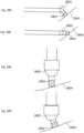
- an ultrasonic probe 800 may comprise a shaft 802 and an ultrasound transducer 804 coupled to a distal end 806 of the shaft, for example as shown in Fig. 8
- the shaft 802 may be straight or may have one or more bends 807 between the distal end 806 and a proximal end 808 coupled to a handle 810.
- the bends in the shaft may be configured to complement bone structures within the nasal cavity in order to facilitate insertion into the nasal cavity and contact between the ultrasound transducer and tissue surfaces.
- the bends may form an angle between a distal and proximal end of the shaft ranging from 30 0 -90 0 .
- the distal portion end of the shaft may be between 5 mm and 20 mm.
- the angle of the ultrasound transducer relative to the longitudinal axis of the distal tip of the shaft may be based on the modality of ultrasound that the probe is intended to utilize. For example, because the angle of incidence between the direction of blood flow and the axis of energy transmission can affect the magnitude of the detected Doppler signal, the angle at which the ultrasound transducer is mounted to the distal end of the probe may be such that the transmission path of the transducer is aligned with the axis of the distal arm. Alternatively, the transducer may be mounted such that the axis of the transducer probe is at some non-parallel angle relative to the axis of the arm. The orientation of the transducer probe axis relative to the distal arm may be fixed.
- a shaft 902 of a surgical probe 900 may include an articulating joint 904 between the proximal end 906 of the shaft, and the distal end 908 of the shaft including the ultrasound transducer 910. While the distal portion 908 of the ultrasound probe is positioned within a general region of the nasal cavity where ablation is likely to be performed, the articulating joint 904 may be used to traverse the mucosal surfaces of the nasal cavity with the ultrasound transducer 910 at the distal tip.
- the processing unit instructs the ultrasound emitter to emit an output signal and further receives a detected signal from the ultrasound receiver.
- the ultrasound output signal passes through tissue and may be absorbed, transmitted or reflected by the internal tissue structures dependent on the ultrasound properties of the tissues.
- the ultrasound energy which is reflected is received as the detected signal, and may be used to identify anatomical features, as discussed above.
- the size of a blood vessel may be measured by scanning the nasal cavity surface with an ultrasound signal and estimating the distance over which a threshold Doppler signal is detected.
- the size of a blood vessel may be measured by physically moving an apparatus that contains a fixed position ultrasound transducer, for example as shown in Fig. 8 , or moving a portion of an apparatus with the ultrasound transducer relative to the rest of the apparatus, as shown in Figs. 9A-C .
- steered ultrasound beams for example with a phased array, may be used to scan the scan region.
- pulsed Doppler techniques are used at varying depths to estimate the thickness of a vessel in the direction parallel to the beam transmission axis.
- the processing unit may have predetermined Doppler signal thresholds set corresponding to typical blood flow in a targeted vessel (for example, the SPA), in order to determine if a detected blood flow is from the vessel of interest.
- Wall filters and other processing may be implemented to isolate blood flow from low velocity clutter signals which improve the performance of the processing unit when demarcating vessel boundaries.
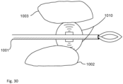
- the ultrasound probe may be traversed along surfaces where the SPA is anticipated to be located.
- the ultrasound probe 1000 may be traversed from a first position 1001 to a second position 1002 which in this example are on either side of the SPA 1003.
- the Doppler signal has a peak amplitude at a position between the first position and the second position, as shown in Fig. 10B .
- an alert in the form of an audio or visual or tactile/haptic indication may be executed in order to notify the operator that a blood vessel, for example the SPA, is located.
- the alert is provided as soon as the Doppler signal surpasses a previously defined threshold corresponding to a threshold associated with the expected blood flow of the blood flow being searched for.
- the full scan from the first position to the second position takes place, the peak from the complete scan is identified, and the alert is provided as the ultrasound probe re-traces its path back towards the first position.
- an ultrasound probe may include more than one ultrasound emitter and/or more than one ultrasound receiver attached at different portions of the ultrasound probe.
- a plurality of ultrasound signals corresponding to different positions of the probe may be processed by a processing unit to determine the position of an anatomical feature, such as the SPA or a foramen, relative to multiple positions on the probe.
- the ultrasound transducers may be arranged such that the there is a fixed distance between them.
- the ultrasound transducers may be arranged in a linear fashion, for example as shown in Fig. 11A .
- the probe 1100 includes three ultrasound transducers 1102, including a left 1102-1, a center 1102-2 and right 1102-3 in a line on a crossbar 1104 at the distal end of the probe.
- the crossbar 1104 is perpendicular to the longitudinal axis of the shaft 1106 of the probe.
- the angular position of the left and right ultrasound transducers is fixed and movement is limited to position shifts that change the proximity of the transducers with relation to the center transducer.
- the insonification angle of the transducers may be variable with or without accompanying overall position changes.
- the ultrasound transducers may be arranged in a rectangular array or circular array.
- ultrasound transducers may be used, for example four transducers in a circular pattern facing in opposite directions at the distal end of a probe shaft and configurations with five transducers in a line along the longitudinal axis of the probe shaft with each facing the same direction.
- Arrays of ultrasound transducers have the advantage of allowing for larger areas to be scanned at once as well as providing a more accurate determination of the location of anatomical features relative to different portions of the probe.
- a probe 1100 may be positioned in the nasal cavity in the general area where the SPA 1108 is located. The probe 1100 may be traversed until one or more of the ultrasound transducers 1102 detects a Doppler shift indicating blood flow associated with the SPA 1108.
- Fig. 11B only the left ultrasound transducer 1102-1 is incident to the blood flow through the SPA 1108. Therefore, as shown in Fig. 11C only the left ultrasound transducer detects a meaningful Doppler signal while the center and right transducers do not.
- ultrasound units may be positioned on independently steerable arms branching out from a main shaft of a probe.
- ultrasound transducers 1302 in an array may be moveable along a crossbar 1304 of a probe 1300 as shown in Figs 13A and 13B .
- left 1302-1 and right 1302-3 transducers are located in recessed tracks within the crossbar 1304 section of the probe 1300.
- the positions of the left 1302-1 and right 1302-3 ultrasound transducer units may be altered in tandem or independently and the center transducer 1302-2 may be coupled to the crossbar 1304 at a fixed position.
- the position of the transducers is altered using buttons, toggles, sliders, and/or dials located at the proximal handle end of the probe.
- a surgical probe may include visual indicators which indicate information about the location of the anatomical features detected by the ultrasound transducers.
- the visual indicator may provide feedback for adjusting the orientation of a probe for locating the SPA.
- the visual indication may be displayed with an LCD (or other type screen), a single LED or an array of two or more LEDs.
- Information about the location may be related by different intensities, different colors, or patterns of on/off (i.e. blinking pattern), and/or color of multiple LEDS.
- the LEDs may be multi-color LEDs and the processing unit controls the LEDs to display a different color based on predetermined thresholds of ultrasound corresponding to different detected thicknesses or distance.
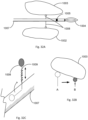
- an ultrasound probe 1400 may include an LED 1402 at the distal tip proximate to the ultrasound transducer 1404. As the probe 1400 is traversed in the vicinity of the SPA 1406, for example as disclosed in relation to Fig. 10A , the LED 1402 provides an indication when the ultrasound transducer detects a Doppler shift resulting from the blood flow in the SPA. In embodiments, LEDs may blink at different rates or patterns to indicate the intensity of an ultrasound signal to locate an anatomical feature.
- an operator may visually observe the LEDs either directly or through a camera imager inside of the nasal cavity to receive the direction information indicated by the LEDs to determine the position of the anatomical features relative to the probe.
- the LEDs corresponding to the ultrasound units may be external of the nasal cavity while the device is in use.
- a probe may include multiple visual indicators corresponding to multiple ultrasound transducers.
- Figs. 15A and 15B show a probe 1500 similar to the probe of Fig. 11A .
- the probe includes an LED 1503-1 1503-2 and 1503-3 corresponding to each ultrasound transducer 1502-1 1502-2 and 1503-3.
- the LEDs are located proximate to the corresponding ultrasound transducer. An operator may traverse the probe within a nasal cavity and the processing unit will adjust the intensity of each LED to correspond to the ultrasound signal amplitude measured by the corresponding ultrasound transducer.
- the intensity of the LEDs may vary continuously based on ultrasound signals as shown in Fig. 16A , or discretely based on preset thresholds of ultrasound signals as shown in Fig. 16B . In embodiments, the intensity of the LEDs may vary based on time of flight pulse-echo ultrasound measurements of the distance to a highly reflective tissue interface, such as the sphenoid bone. Further, in embodiments, the processing unit may display the amplitudes of the ultrasound units on a display. In embodiments, the processing unit may display images indicating the location of the anatomical features, for example the SPA.
- ultrasound transducers and probes may be part of a surgical probe including an ablation element, in particular a cryo-ablation element.
- Figs. 17A-17D show views of the distal end of an embodiment of a surgical probe, particularly an ablation probe, comprising an expandable membranous structure which may be used when a target treatment site is located.
- the ablation probe shown is an example and other cryo-ablation probes, as well as other types of ablation probes, may be used with the disclosed ultrasound technology disclosed herein.
- the ablation probe is configured with expandable membranous structure functioning as a liquid cryogen evaporation chamber. Liquid cryogen enters the interior of expandable membranous structure. Evaporated cryogen gas exits the interior of expandable membranous structure through fenestration(s) 147 in distal end 146 of probe shaft 145 and exits proximally into the room.
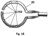
- a structure or member 83 is formed into a looped and elongated structure having arcuate edges for presenting an atraumatic surface.
- the structure 83 may be formed of a relatively rigid wire or spring like material which maintains its configuration when pressed against a tissue surface.
- Structure 83 may form a continuous structure which defines an opening there through such as a looped or elongated and looped member which is open through the loop.
- the structure 83 may be contained entirely within the expandable structure 81 which may be formed to have a predefined shape which is distensible or non-distensible when inflated by the cryogen.
- the expandable structure 81 may be formed to surround the structure 83 entirely without being supported by or attached to the structure 83 itself.
- Such a structure 83 may provide a configuration which presents a low-profile as the device is advanced into and through the nasal cavity and between the nasal turbinate tissues. Yet because of the relatively flattened shape and rigidity and integrity of the structure 83, the structure 83 may be used to manipulate, move, or otherwise part the tissues of the nasal cavity without having to rely upon the expandable structure 81. Additionally, the low-profile enables the structure 83 to be positioned desirably within the narrowed confines of e.g., the cul-de-sac in proximity to the posterior nasal nerves.
- the expandable structure 81 When the expandable structure 81 is in its deflated state, it may form a flattened shape and when inflated, the expandable structure 81 may inflate into a configuration which remains unsupported by or attached to the structure 83. Because the structure 83 may be formed of a member which solid along its length, the cryogen may be introduced directly into the expandable structure 81 through a distal opening defined in the probe shaft 145.
- structure 83 may be formed of a hollow tubular member which itself is formed into the continuous or looped shape.
- the cryogen may be optionally introduced through the hollow tubular member and dispersed within the interior of the expandable structure 81 through one or more openings which may be defined along the tubular member.
- the structure 83 may be formed into a flattened shape rather than a looped shape. In this configuration, the structure may be either solid or hollow such that that cryogen may be introduced through the structure and into the interior of the expandable structure 81 via one or more openings defined along the structure.
- the structure 83 may extend and remain attached to the probe shaft 145, but the remainder of the structure 83 which extends within the expandable structure 81 may remain unattached or unconnected to any portion of the expandable structure 81.
- the structure 83 may be adjusted in position or moved via manipulating the probe shaft 145 relative to the interior of the expandable structure 81 to enable the targeted positioning and cooling of the tissue region when in contact against the outer surface of the expandable structure 81.
- the structure 83 may press laterally upon a particular region of the underlying tissue to stretch or thin out the contacted tissue region to facilitate the cryogenic treatment.
- the expandable structure 81 may remain in a static position against a contacted tissue region allowing for limited repositioning of the structure 83 within.
- Fig. 17B shows a side view of the embodiment of Fig. 17A illustrating how the structure 83 can be formed from a relatively flattened configuration relative to the inflated expandable structure 81. Because of the structural integrity of structure 83 and its relatively flattened profile, the structure 83 may provide for targeted treatment of the tissue when contacted by the device.
- Fig. 17C shows the side view of the inflated expandable structure 81 when pressed in a longitudinal direction by its distal tip against the underlying tissue surface S. The relative strength of the structure 83 provides for the ability to press the device against the tissue surface such that the remainder of the expandable structure 81 may maintain its inflated configuration to potentially insulate the other surrounding tissue regions.
- Fig. 17B shows a side view of the embodiment of Fig. 17A illustrating how the structure 83 can be formed from a relatively flattened configuration relative to the inflated expandable structure 81. Because of the structural integrity of structure 83 and its relatively flattened profile, the structure 83 may provide for targeted treatment of the tissue when
- 17D likewise shows the device when the structure 83 is pressed laterally along its side against the tissue surface S such that the structure 83 lies flat.
- the contacted tissue region may be treated while the remainder of the surrounding tissue is potentially insulated by the expanded structure 81.
- Further exemplary ablation devices for use with the present invention are described in U.S. 14/503,060 filed September 30, 2014 and U.S. 62/408,920 filed October 17, 2016 .
- ultrasound transducers may be attached to a support member within a balloon as shown in Fig. 17A .
- this balloon may be selectively filled and drained with an acoustic coupling agent such as a gel or a fluid.
- the balloon is filled with fluid to allow for better acoustic coupling during ultrasonic sensing and positioning, then drained of fluid once the device is in place and ablation is desired to be performed, for example by releasing a cryogen into the area encompassed by the balloon.
- ultrasound transducers 1702 are mounted on a loop-like support structure 83 that is shown in Fig 17A and in Fig 18A-C and may be used to scan tissue within the nasal cavity, as discussed herein.
- an ultrasound probe and an ablation probe may be integrated into a single probe with a single shaft.
- a shaft 1902 of a probe 1900 may include an ultrasound transducer 1904 at the distal end and an ablation element portion 1906, for example a cryo-balloon along the shaft of the probe.
- the shafts may include articulation joints 1908, which may be used to perform scans with the ultrasound probe while the cryo-ablation elements remains stationary of is required to move less relative to the ultrasound transducer.
- an integrated probe may include a plurality of ultrasound transducers, which are used to locate an anatomical features, such as the SPA or a bony landmark, as disclosed above.
- the ultrasound transducers may be positioned at any position along the longitudinal shaft of the probe, the cryo-ablation element, or an auxiliary shaft including a crossbar.
- an integrated probe 2000 includes a crossbar 2002 with three sets of ultrasound transducers 2004 at the distal end, and an ablation member 2006 along the shaft 2008.
- ultrasound transducers may be attached to the balloon of the cryo-ablation element. For example, as shown in Fig.
- multiple ultrasound units may be used by a processing unit to more precisely and/or more quickly locate the SPA or other vessels or anatomical features.
- the processing unit may acquire a signal from each independent ultrasound unit and analyze the signals to generate directional information regarding the position of the SPA relative to the cryo-ablation element.
- the signals from individual ultrasound transducers may be combined or averaged prior to processing.
- a multi-element transmit and receive array may provide benefits including the improvement of lateral image resolution.
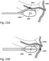
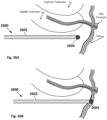
- an ultrasound transducer 2302 may be offset from the center 2303 of the cryo-ablation element 2304 and epicenter of ablation so that ablation may be performed when the ultrasound transducer is positioned above a blood vessel 2305, for example the SPA, and therefore prevent direct treatment of the SPA.
- the ultrasound transducer may be offset by a distance "d" from the center of the ablation probe and treatment epicenter, wherein the distance corresponds to a distance between a blood vessel to be avoided and a nerve to be treated.
- the ultrasound transducer 2302 may be offset in a lateral orientation, as shown in Fig. 23A , or a distal orientation as shown in the Figs 23B-23D .
- the surgical probe may be advanced into the nasal cavity and the offset ultrasound transducer may scan tissue, as disclosed above, in order to locate a blood vessel.
- the transducer over the blood vessel, for example the SPA as shown in Figs. 23A-D
- the cryo-ablation element will not be over the SPA.
- cryo-ablation is performed with the assurance that the SPA is not at the epicenter of the ablation zone and will not receive direct treatment.
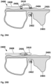
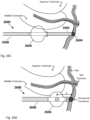
- Figs. 24A and 24B show embodiments of combined ablation and ultrasound sensing probes 2400 configured to interrogate the posterior fontanelle, palatine bone 2402 and sphenoid bone 2403 and surrounding tissues.
- A-mode ultrasound scans may reflect signals that allow for differentiation between different thicknesses of mucosal tissue, bones, and bone and cartilage boundaries. For example, differentiation between thin cartilage of the fontanelle and thin palatine and/or thick sphenoid bone may be detected.
- One way in which the signals may differ may be in the amplitude of reflected signal.
- a plurality of ultrasound transducers 2406 may be coupled to the probe shaft 2408 both more distal of the cryo-ablation element 2410 and more proximal of the cryo-ablation element 2410, for example as shown in Fig. 24A .
- the two ultrasound transducers may be used to detect anatomical features on either side of the cryo-ablation element.
- the ultrasound transducers may be used to detect different thicknesses or composition of tissue 2405 corresponding to a target treatment site of a nerve. To detect this difference the probe 2400 is advanced into the nasal cavity and scanned along tissue within the nasal cavity until the distal transducer detects a signal characteristic of one tissue configuration and the proximal transducer detects a signal characteristic of a different tissue configuration.
- the flowrate or discharge time of the cryogenic liquid that evaporates in the cryo-ablation element may be reduced to ensure ablation does not penetrate too deep and damage tissue that it not in the target treatment area.
- bone/soft tissue changes are used as indicators for the location of a treatment site. The transition of 0.5-1 mm thick cartilage to 1-3 mm thick bone may indicate that the probe has reached the perpendicular plate of the palatine bone where the nerves innervate the nasal cavity and this transition may be used to determine the target treatment site. In embodiments, a bone to bone transition between the palatine and the sphenoid bone may be detected by a transition from 1-3 mm of bone thickness to >4 mm of bone thickness.
- the location of the palatine canal may be determined in order to avoid treatment to nerves within the palatine canal.
- a single ultrasound transistor 2406 of a probe 2400 may be used to detect bone and tissue thicknesses and transitions as discussed in relation to Fig. 24A .
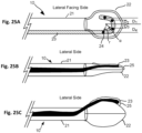
- the ultrasound transducers 24 are configured in an array on the lateral side of the ablation probe positioned a distance r from the epicenter of ablation zone and an angle ⁇ away from each other to define an area within the ablation zone that if arteries are identified within this region the device provides a notification not to ablate or will prevent ablation from being initiated.
- the radius can be defined between 1-8mm, preferably 6 mm.
- the angle between the transducers can be 5-180 deg. preferably 45-90 deg.
- the number of transducers can be 2-10.
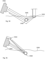
- Fig. 25A illustrates the lateral face of the embodiment.
- Probe 10 comprises of an integrated sensing element 23 with ultrasound transducers 24 embedded and an ablation element 22 affixed to a cannula 21.
- the sensing element 23 is affixed to bottom or top of the cannula 21 in line with the vertical axis of the lateral plane to keep the profile in the horizontal axis as low as possible.
- Electrical or flex circuitry runs the length of the cannula from the ultrasound sensors to a controller inside a hand piece or box.
- Fig. 25B shows a top view of probe 10 in the collapsed configuration.
- a coat of a gel like substance 23 lubricates at least the lateral side of the probe around the transducers to create an acoustic friendly environment and make translation on the mucosa easier.
- This configuration is designed to allow the user to advance the probe in to the nasal cavity and position the ablation element 22 in the target area.
- the ablation element 22 is expanded to press the transducers 24 onto the lateral wall of the nasal cavity.
- Fig. 25C shows an expanded state of probe 10. Once the transducers are in contact with the wall, an indication is provided the ablation probe is appropriately placed and free of main branches of the SPA by an audible, visual or tactile signal.
- the indicator will be affixed along cannula 21 so it can be visualized within the nasal cavity using the rigid endoscope that is being used to visualize the target area. If placement is correct and safe, the embodiment will inform the user and the user will activate ablation. If there is an artery detected, the probe will inform the user and ablation may not be allowed to activate. In this case, the user will translate anterior or posterior until the ablation element is free of vasculature and the user will be informed and ablation will be allowed.
- a cryo-ablation element may be slideably coupled to the probe shaft of an ultrasound probe, for examples as shown in Figs. 26A-D .
- ultrasound probe 2600 comprises a shaft 2602 with an ultrasound transducer 2604 disposed at the distal end.
- the ultrasound probe 2600 may be inserted into the nasal cavity with the cryo-ablation element 2606 remaining outside of the nasal cavity.
- the ultrasound transducer 2604 may be swept along tissue within the nasal cavity in order to detect an anatomical features, for example a blood vessel or anatomical features (e.g. tissue thickness, bone thickness, transition/boundary) as discussed above.
- a target treatment area may be determined based on the determined location of the anatomical feature.
- the anatomical feature may be the SPA and the target treatment site may be determined to be a predefined distance from the SPA corresponding to the distance between the SPA and the PNN.
- cryo-ablation element 2608 With the ultrasound transducer 2604 held against the SPA, as cryo-ablation element 2608 is advanced along the shaft 2602 of the ultrasound probe, for example as shown in Fig. 26C .
- the cryo-ablation element may be advanced through a lumen in the ultrasound probe or may use the shaft of the ultrasound probe as a rail.
- a cryo-ablation element 2606 is coupled to shaft 2608, both of which have a lumen that surrounds and slides over shaft 2602
- the cryo-ablation element may comprise an inflatable structure with a lumen that surrounds and slides along the shaft of the ultrasound probe.
- the cryo-ablation element 2606 may be advanced to the predetermined distance "d" from the ultrasound transducer and ablation may be performed at the target treatment site.
- the ultrasound probe may be configured like a flexible or rigid guide wire over which the ablation probe may be introduced to the ablation site.
- the ultrasound probe as a guide for the slidable cryo-ablation element is advantageous since it allows for the target treatment site to be located with a small device, and further allows the cryo-ablation probe to reach the target treatment site more precisely compared to an unguided device.
- the sensing or combined ablation and sensing probe may contain stabilization elements.
- Relative tissue/transducer motion that is parallel to the angle of ultrasound transmission but unrelated to blood flow may add unwanted noise to or confound Doppler measurements. For example, slight shifts in probe position, for instance those arising from an unsteady hand of an operator holding the probe, occurring while measurements are being made may create a Doppler-type effect. This could reduce performance for locating the SPA and as such extend procedure time or lead to errors in determining the proper location of treatment.
- an inflatable balloon may be attached to the shaft of the probe and used to stabilize the ultrasound transducer while ultrasound scans are performed.
- the balloon When a Doppler scan is to be performed the balloon inflates and applies transient pressure against nearby structures as a way to stabilize the position of the probe relative to surrounding tissues, thus reducing motion unrelated to blood flow and increasing the accuracy of the Doppler signal.
- the balloon may be deflated when it is desired to reposition the probe.
- the balloon may be re-inflated when additional Doppler measurements are taken.
- the stabilization balloon may not be inflated.
- a single stabilization balloon is utilized.
- multiple balloons may be used, for example a stabilization balloon located on either side of the ultrasound transducer.
- a plurality of balloons may be proximate to some or all of these transducers.
- the balloons may encompass the ultrasound transducers.
- the transducers may be attached to the exterior of the balloons.
- stabilization mechanisms may also include suction, coiling, and tines extending from the probe employed to stabilize probe position.
- the quality of acoustic coupling between the ultrasound transducer and tissue is important for achieving accurate measurements for all modes of ultrasound. Without proper acoustic coupling, large reflections at the transducer/air interface essentially prevent ultrasound waves from reaching tissues.
- One mechanism for ensuring quality acoustic coupling is to place the ultrasound transducer directly in contact with tissue so that there is no air gap. To aid in ensuring sufficient contact, suction may be employed.
- a lumen may be incorporated through the shaft of an ultrasound probe containing one or more ultrasound transducers. Air may be pushed or pulled through this lumen.
- One or more openings may be placed at the distal end of the probe in proximity to the ultrasound transducer.
- suction When the ultrasound transducer is brought in proximity with tissue, suction may be applied to the openings near the transducer and that suction may draw the transducer more closely to the tissue until the openings make contact with the tissue and lock the device in place. Suction may be maintained during ultrasound measurements to ensure sufficient contact for quality energy coupling and signal transmission across the tissue-transducer interface. Ablation is also dependent upon contact between the ablation member and the tissue surface. The system and methods described above may be used where the openings are in proximity to the ablation member and where suction is applied to make sufficient contact during treatment.
- ultrasound signals from during a cryo-ablation treatment may be analyzed by the processing unit to determine if the mucosa or a blood vessel, for example the SPA, is being damaged during treatment. For example, blood flow through the SPA during ablation may be monitored, and the detected blood flow may be used to determine the duration of the ablation. If the blood flood is detected to be reduced below a preset threshold the ablation may be terminated.
- the target ablation sites may be immediately adjacent to the determined location of the SPA, for example 1-5 mm, in order to avoid freezing directly over the SPA.
- Embodiments further include systems and methods for assessing the effect of a treatment performed in the nasal cavity.
- a chemical or pharmacologic intervention such as the application of a steroid, antibiotic, or other substance can be assessed using ultrasound scans as disclosed herein.
- Embodiments are also used to assess the impact of mechanical interventions, including artery ligation, neuromodification procedures such as neurectomy, neuroablation, and/or selective postganglionic pterygopalatine parasympathectomy (SP3), and other tissue remodeling procedures such as turbinate reduction.
- assessments are made as stand-alone single session evaluations.
- the assessments are the result of comparison of evaluations obtained before and after an intervention has taken place.
- comparisons are made using evaluations captured after a period of time has elapsed following an intervention, allowing time for full therapeutic effect to be achieved and for the resolution of any acute post-procedure effects such as swelling or inflammation. In embodiments this period of elapsed time is 7 - 30 days following an intervention. In embodiments, comparisons are made using evaluations captured immediately or nearly immediately following an intervention, for example 5 - 30 minutes following an intervention.
- Embodiments include the use of an ultrasound transducer connected to the shaft of a catheter or probe and inserted into the nasal cavity.
- the transducer may be a single element transducer or an array of multiple or many elements (for example, up to 72 elements).
- the transducer may be configured to operate in A-mode, M-Mode, Doppler mode(s), and/or B-mode (for embodiments involving transducer arrays only). Processing techniques, such as elastography imaging or assessments involving spectral analysis, may be implemented in some embodiments.
- an assessed parameter includes the thickness of mucosal tissue in the nasal cavity. Comparisons may be made between mucosal thickness evaluated before and after an intervention in order to assess the effect of the intervention.
- Ultrasound waves emitted from a transducer will be scattered, absorbed, and reflected by tissues.
- the degree of reflection will be largely governed by changes in the acoustic impedance of tissue that a traveling wave encounters.
- Bone (and cartilage) and mucosal tissue have large differences in acoustic impedance, and large amplitude ultrasound wave reflections will occur at the interface between bone (or cartilage) and mucosal tissue.
- the transition between mucosal tissue and bone is detectable in ultrasound data.
- the interface is represented by a large amplitude spike an in A-mode ultrasound trace or as a bright linear region in an M-mode or B-mode ultrasound image.
- Embodiments will use a transducer operating at a frequency of 8 - 20 MHz and preferably 12 - 15 MHz.
- the mucosal tissue is soft and may be deformed with pressure applied via an apparatus. As such the thickness of mucosal tissue may be altered through the contact of an ultrasound transducer to the nasal cavity wall.
- Embodiments will include mechanisms or methodological steps to ensure that each thickness evaluation utilized for comparative purposes is taken with an identical or nearly identical degree of pressure applied to the mucosal surface.
- the ultrasound transducer is mechanically coupled to a force sensor such as a pressure sensor, force plate, or strain gauge to assist with controlling pressure applied to the mucosal tissue while making tissue thickness measurements.
- a force sensor such as a pressure sensor, force plate, or strain gauge to assist with controlling pressure applied to the mucosal tissue while making tissue thickness measurements.
- one or more pressure sensors are mounted on the tissue contacting face of the transducer.
- one or more pressure sensors are mounted on a probe or catheter shaft adjacent to the transducer.
- the sensors are adapted to send readings along sensor wires located in a lumen of the probe or catheter shaft to a handpiece of the apparatus.
- Software algorithms interpret signals from the sensor, for example electrical signals from a strain gauge or force plate, and convert the information to a pressure or force.
- the actual force or pressure readings are provided to a user.
- the force or pressure readings are not provided to a user, but instead the apparatus provides the user with an indicator that the contact force is within an acceptable range for a valid measurement.
- the apparatus may provide a visual, audio, or tactile indicator if contact force is too minimal, acceptable, too aggressive, or some combination of these ranges.
- contact force or pressure information is not provided to the user in any way.
- algorithms making mucosal thickness measurements automatically adjust the calculation based upon the contact force.
- the elastic modulus (Young's modulus) of mucosal tissue is generally known, as is the Poisson ratio and other material properties required to translate a contact force to an estimated longitudinal strain.
- an embodiment may use ultrasound time of flight algorithms to estimate the thickness of mucosal tissue, then improve this estimate by adjusting the originally calculated thickness by a factor which accounts for deformation due to the contact pressure or force.
- contact force is not measured with a sensor, but is controlled via a mechanical means.
- a spring mechanism is located at or near the tissue-contacting face of the transducer. The spring constant of the spring is selected such that a certain small range of suitable forces will be required to be applied to the mucosal tissue in order for the transducer to make adequate tissue contact.
- contact force is controlled by a compliant coupling balloon, for example a balloon comprised of silicone rubber.
- the balloon may initially be configured in a deflated state for insertion of a catheter or probe into the nasal cavity.
- the user may expand the balloon, for example by filling the balloon with a fluid or gel-like substance infused through a lumen in the shaft of the catheter or probe.
- a syringe containing a fluid may connect to a luer-type interface on the handpiece of the apparatus, wherein depressing the plunger on the syringe forces the fluid along the lumen of the apparatus and into the balloon, causing it to expand.
- the balloon When the balloon is expanded, it makes contact with mucosal tissue. Due to the compliant nature of the balloon, the shape of the balloon will mold to the shape of the mucosal tissue without applying a force that is sufficient to compress of deform the tissue. In embodiments, the transducer remains a small distance, for example 1-5 mm, away from the mucosal wall to ensure no contact force is applied.
- the fluid or gel used to expand the balloon provides sufficient acoustic coupling such that the ultrasound waves may appropriately interrogate the mucosal tissue.
- the apparatus includes a mechanism to collapse the balloon by removing the fluid or gel, thus allowing for the distal portion of the apparatus to return to its original slimmer profile which will facilitate removal from the nasal cavity.
- Fluid or gel can be removed by applying a vacuum or suction to the port on the apparatus handpiece that had previously been used to convey the fluid or gel into the balloon. With the application of negative pressure, the fluid or gel will be drawn back through the delivery lumen towards the handpiece and allow for the balloon to collapse.
- multiple lumens are used for delivery and/or removal of fluid or gel to/from the balloon.
- the transducer is positioned a small distance from the leading edge of the mucosa, for example in embodiments that utilize a coupling balloon
- algorithms to determine mucosal thickness may be refined to address additional echoes originating from the interface between the fluid/gel/balloon-mucosa boundary.
- the difference in acoustic impedance at this boundary is expected to be much lower than the difference at the mucosa-bone/cartilage boundary, and as such the reflection will be of relatively smaller amplitude and easily discernible from the larger reflection produced at the interface with bone or cartilage.
- the mucosal thickness may be estimated using the time difference between the detection of these two spikes in a received ultrasound signal.
- the thickness measurement of mucosal tissue are dependent on the angle of incidence of the ultrasound beam.
- an orthogonally-aligned transducer produces a thickness estimate that is smaller relative to an estimate in the same region when the transducer is obliquely-aligned (and thus has a longer path through the tissue).
- this discrepancy may be controlled for if the incidence angle is known, doing so is expected to be a challenging and low-accuracy task. It is thus desirable to account for the angle of incidence variations in a pro-active manner.
- a transducer is mounted on a movable axis, for example on a pivot joint or ball-joint, such that it becomes “self-aligning", for example as shown in Figs. 28A-D and 29 . That is, whenever a transducer is pressed against a surface, the position of the transducer moves along the axis such that it naturally aligns in an orthogonal fashion.
- contact sensors for example electrical impedance sensors or force sensors, may be used at one or more locations on or near the transducer face to ensure orthogonal contact.
- transducers are configured to scan through a range of incidence angles. For example, in a phased array, the transmission delay between individual elements is adjusted to steer the resulting ultrasound beam through a number of angles, collecting data at each.
- the transducer may be mechanically swept through a range of angles, for example from -45 degrees to + 45 degrees, collecting data at multiple angles in the range.
- a number of calculations of mucosal thickness may be made, and the minimum thickness may be selected as the gold-standard measurement that is representative of an orthogonal incidence angle.
- the maximum thickness may be analyzed, or some combination of the various thickness measurements made at the angles interrogated.
- Embodiments may include detection and analysis of echogenicity.
- One impact of nasal cavity interventions may be a change in the level of edema or fluid in the mucosal tissue.
- a change in the level of edema, fluid, and/or swelling may be indicative of symptomatic relief and as such indicative of the therapeutic efficacy of an intervention. Changes in these properties of mucosal tissue may be assessed with ultrasound and thereby be useful to physicians and patients.
- Mucosal assessments may be made with ultrasound by examining the echogenicity of the mucosal tissue.
- echogenicity is a characteristic of tissue that describes how it responds to ultrasound interrogation - i.e. how it absorbs, scatters, and reflects incident ultrasound energy.
- the brightness (in B-mode) or reflected signal strength (in A-mode) would be indicative of echogenicity.
- Other tissue characteristics captured by an ultrasound beam for example speckle texture, spectral energy content, and attenuation constant (inherently linked to the absorption coefficient) - may also be useful for interrogating tissues. It is known by those skilled in the art that changes in tissue edema/water content alter the ultrasonic properties of tissue, for example the speed of sound and the absorption coefficient.
- one or more ultrasound signals is transmitted into mucosal tissue and the corresponding echoes are received.
- Received radiofrequency data may be processed in order to extract brightness data, for example algorithms related to quadrature demodulation, envelope detection, rectification, and/or involving the Hilbert transform may be used to better extract brightness data.
- resulting brightness data is assessed over a window where the mucosa is detected to be (for example, in a region bounded by large reflection spikes that signify balloon/mucosa and mucosa/bone interfaces, respectively).
- brightness data may be assessed across a tissue window that spans both depth and a width determined by the size of the transducer array.
- comparisons are made between measurements captured before and after a nasal cavity intervention in order to assess a change.
- spectral analysis may examine the frequency content of returning echoes to assess changes. For example, a reduction in fluid content in mucosa may change the absorption properties of the tissue in a way that results in a frequency content shift of acoustic backscatter measured by the transducer.
- received radiofrequency data may be converted into the frequency domain using techniques such as the Fast Fourier Transform (FFT) and analyzed to determine the power density of the frequency content. For example, in the presence of moderate or severe mucosal edema, the attenuation coefficient may be reduced. The attenuation coefficient for ultrasound is frequency dependent, and as such a spectral shift of the power density may occur.
- FFT Fast Fourier Transform
- an ultrasound array may be configured to estimate the mechanical properties of tissue using elastography or elasticity imaging, for example vibrational elastography, acoustic radiation force impulse imaging, or shear wave elasticity imaging.
- elastography or elasticity imaging for example vibrational elastography, acoustic radiation force impulse imaging, or shear wave elasticity imaging.
- an ultrasound transducer composed of an array of individual elements is mounted on the shaft of a probe or catheter and inserted into the nasal cavity.
- an initial ultrasound scan of the area is acquired.
- the array is operated in an excitation mode, sending a high intensity focused pulse of ultrasound into mucosa. This pulse displaces tissue in the focal zone using a radiation force and creates a shear wave that will travel away from the excitation site at a speed directly proportional to the shear modulus of the tissue.
- the transducer is configured to deliver a series of subsequent tracking pulses in locations adjacent to the location of the excitation pulse. These tracking pulses are similar or identical to standard B-mode ultrasound pulses.
- these tracking pulses can be utilized to monitor the propagation of the induced shear wave in tissue.
- the shear modulus, and thus ultimately the elastic modulus, of the mucosa may be determined.
- insights into the impact of the intervention may be obtained.
- ultrasound measurements may be taken during treatment to detect changes in tissue characteristics associated with tissue freezing. These measurements may be used to detect the state of the target tissue.
- the state of the tissue may be used during treatment to adjust treatment dose parameters including treatment time or the number of freeze-thaw cycles. For example, ice crystals formed during cryo-ablation may increase scattering and/or reflection of ultrasound waves in the treatment region.
- the proximal edge of a cryo-ablation treated area may appear hyperechoic (bright) with large hypoechoic (dark) regions more distal from the transducer due to strong reflections at the ice ball interface and associated acoustic shadowing.
- a change in echogenicity (strength of received echoes) across a region of certain size may signify that treatment is sufficient and that the procedure may end.
- an acoustic shadow at least 5 mm wide may be seen as indicative of sufficient freezing.
- different size regions, for example 2 mm or 10 mm wide may be viewed as more appropriate to signify that sufficient freezing has occurred.
- these changes are measured using the strength of the signals measured during an A-mode ultrasound scan.
- One benefit to stopping a treatment at or shortly after sufficient freezing has occurred is that it reduces the risk of unwanted collateral tissue damage in regions outside of the intended treatment area.
- transducers are built into the probe shaft to assess the lateral growth of the ice ball created during cryo-ablation.
- the cryo-ablation element freezes a region of the mucosal tissue to form an ice-ball that may be ellipsoidal in profile shape, and the depth of the treated region may be related to the width of the frozen region.
- monitoring lateral growth of the frozen region over time is used to determine the depth of the frozen region, which in turn is used to determine the length of treatment.
- multiple transducers are mounted on the probe shaft so as to interrogate tissues at fixed lateral distances from the ablation member, for example at 5mm, 10mm, and 15mm from the member.
- a single transducer may slide along a recessed path in the shaft (similar to as shown in Fig. 23 ) so as to interrogate tissues at various distances from the ablation member. In embodiments, a single transducer may be used at a fixed distance.
- a combined ablation and sensing probe 102 contains an ablation element 103 and an ultrasound transducer 104 located a distance r 1 distal to the ablation element.
- the transducer is angled an angle ⁇ with respect to the longitudinal axis of the probe shaft and is aimed in the direction the ice ball is expected to form during cryo-ablation.
- the ultrasound transducer 104 scans tissue with the probe 102 positioned between the middle turbinate 101 and inferior turbinate 107, for example using A-mode imaging techniques, and receives a normal pattern of echo signals associated with soft tissue scanning.
- the ice ball in the frozen region 108 in the tissue 105 grows, it enters the path of the ultrasound beam 110 and changes the received echo pattern.
- the new echo pattern may be characterized by a hyperechoic area at the boundary of the ice ball followed by hypoechoic regions associated with acoustic shadowing.
- An advantage of the distal location of the ultrasound sensor on the probe is that it allows for an interrogation path that originates posterior to the middle turbinate 101, which may limit or eliminate echo interference associated with the bony prominence 106.
- the ultrasound sensor may be located more proximal on the probe shaft than the ablation element.
- the angle ⁇ of the axis of the beam of the ultrasound transducer relative to the axis of the distal end of the probe shaft may be adjustable by the user.
- the geometric tangent can be utilized to calculate the angle ⁇ for the transducer given that r 1 is fixed.
- the transducer angle can be adjusted using dials, knobs, buttons, with a low-power motor/robotic control, or using other methods.
- the angle ⁇ is fixed, but the distance r 1 is adjustable. In embodiments, both ⁇ and r 1 are fixed.
- Ultrasound may further be used to actively monitor tissue thickness changes during treatment.
- the ice crystal formation during cryo-ablation causes tissues to expand when treated. Though the amount of expansion is small, it is within the measurable resolution of ultrasound imaging techniques. After tissue has expanded a certain amount, for example a certain percentage of its baseline thickness (for example, 20%) or to a certain pre-calculated degree (for example, 1 mm), the detected expansion is used as an indication that the treatment is sufficient and that the procedure may end.
- A-mode or M-mode ultrasound techniques may be used to assess this expansion in real time, for example by determining changes in the thickness of mucosal tissue using techniques described previously in this disclosure. Though acoustic shadowing may confound assessment of tissue thickness directly in the treated region, expansion in immediately adjacent regions may be informative for guiding treatment.
- Ultrasound measurements may be taken post treatment to detect changes in tissue properties associated with tissue thawing. These measurements may be used to determine when the device can be safely removed. For example, changes that were measured during treatment, such as alterations in echogenicity, thickness, or other characteristics, may begin to reverse themselves during thawing and approach baseline values. In a treatment paradigm that includes multiple cycles, these measurements may also be used to determine when the next freezing cycle should begin.
- Ultrasound measurements may be taken post treatment to detect changes in tissue characteristics associated with cryo-ablation injury.
- tissue injury may be associated with changes in density or changes in elasticity that are measurable using ultrasound. These measurements may be used to verify that target tissue has been treated.
- M-mode ultrasound measurements may be acquired to assess tissues and/or changes in tissues resulting from ablation treatment.
- M-mode (motion mode) imaging acquires successive scans along the same region of interrogation (i.e. successive A-mode imaging lines) and as such can record how structures move toward or away from the transducer over time.
- tissues may be detected to move differently than when frozen, and treated and subsequently thawed tissues may be detected to move differently than either frozen tissues or untreated tissues.
- M-mode techniques may be used for assessing treatments in both the short- and longer-terms following treatment.
- M-mode imaging is used to track naturally occurring tissue movements, for example physiological motion associated with the pulsation of arterial blood vessels.
- M-mode may be used to track tissue motion that occurs in response to an external stimulation, for example a pulse of acoustic radiation force emitted from the transducer or the application of a vibrating piston oscillator.
- advanced processing techniques such as speckle tracking algorithms may be applied to M-Mode data to extract quantitative information from the scan, for example information about the exact degree of longitudinal tissue movement.
- ultrasound transducers housing may be attached to a probe through a joint capable of flexing or rotating in one or more directions.
- the uneven pressure or force along the interface causes the housing to passively orient itself such that the housing and tissue surfaces are closer to parallel.
- Figs. 28A and 28B show an ultrasound transducer 2802 mounted on single axis joint 2803 to facilitate for orthogonal alignment with tissue surface 2804.
- Figs 28C and 28D show an ultrasound transducer 2802 mounted on ball joint 2805 to facilitate for orthogonal alignment with tissue surface 2804.
- the ultrasound transducer may be housed such that the axis of the transducer and of the housing are at a fixed angle between 0 and 90 0 with each other.
- the axis of the transducer is at roughly the same angle to the tissue as with the housing surface.
- Fig. 29 shows an ultrasound transducer 2902 mounted in housing 2904 at a desired angle with the surface of the housing in contact with tissue.
- the ultrasound beam will be at a desired angle to the tissue surface.
- the housing is constructed such that the material between the transducer and tissue has an acoustic impedance appropriate to maximize ultrasonic energy transmission.
- the transmitted ultrasound signal can be oriented to provide an increased accuracy related to Doppler measurements being made for vessels that run parallel or closely parallel to the tissue surface.
- sensors on the shaft of a probe are used to aid with probe positioning by detecting and using the turbinates within the nasal cavity as guiding landmarks.
- the desired location for cryo-ablation treatment is the posterior 1/3 of the middle meatus, which may be identified generally by the relative position of the turbinates.
- the inferior and middle turbinate may serve as landmarks used to locate the desired region for treatment or narrow the search region for the desired region of treatment.
- the inferior and middle turbinate can be located within the nasal cavity using endoscopic guidance or other methods, so a location technique that uses these features as navigation aids is simple, convenient, and allow for shorter procedure time.
- a probe contains sensors which measure the relative position of a probe to the middle and inferior turbinate.
- the probe may be an ultrasound probe or a combined ablation/ultrasound probe, as disclosed above.
- the sensors may be acoustic, optical, electromagnetic, or mechanical in nature.
- optical (ex. laser) or more general electromagnetic (ex. radar, infrared) sensors may be mounted to a probe shaft and measure distance from the shaft to a reflective surface such as the turbinates using time of flight measurements.
- ultrasound sensors may be used in conjunction with coupling mechanisms that allow the signal to acoustically couple to the turbinate wall.
- the ultrasound sensor may be encased in an inflatable coupling balloon that is filled with gel, water, or another coupling substance that expands outward from the shaft and makes contact with turbinate walls.
- FIG. 30 An example of an embodiment using a coupling balloon is shown in Fig. 30 , with the coupling balloon 1010 serving as the mechanism for acoustically coupling ultrasound energy back and forth from the sensor and turbinates.
- Anatomy in the figure may not be to scale and is provided as a visualization aid only.
- Fig. 30 illustrates a combined ablation and sensing probe that utilizes acoustic coupling balloons.
- Figs. 31A-C show embodiments that utilize the turbinates to guide placement of an ablation probe in a tissue region.
- the figures show the use of a non-ultrasound sensor, however in embodiments ultrasound sensors may be in place of or in addition to the sensors shown.
- a combined sensing and ablation probe 1001 is located in the nasal cavity in the general region between the inferior turbinate 1002 and middle turbinate 1003.
- the probe contains a joint 1005, for example a single-axis joint or a ball joint, that allows the distal end of the probe containing the ablation member 1004 to articulate with respect to the proximal end of the shaft.
- the probe contains sensors 1006 on the superior and inferior aspects of the probe for interrogating the middle and inferior turbinates, respectively.
- the sensors only seek to establish that the turbinates are present within the path of the sensor signals, or alternatively are present within a certain distance d of the sensor.
- the sensing protocol may be binary in nature and seek to determine only if a turbinate is located within 2 mm of the shaft, illuminating an LED if this condition is true.
- the sensors use time of flight or other techniques to measure the distance to each turbinate. Some embodiments may utilize additional sensors in additional locations, for example a sensor on the lateral aspect of the probe shaft for interrogating the lateral nasal cavity wall. As shown in Fig.
- the probe is situated in the nasal cavity such that the sensors on the probe shaft are located within the portion of the middle meatus bounded superiorly and inferiorly by the turbinates. As such signals produced by the sensors interact with the turbinates and inform the operator that it may be desirable to advance the probe more posteriorly prior to initiating treatment. As shown in Fig. 31B , the probe is advanced such that the sensor on the inferior side of the shaft is beyond the proximal boundary of the inferior turbinate, and as such the sensor signal is changed in such a way that the operator may determine that this anatomical landmark has been completely traversed. For example, the sensor may determine the distance to the closest reflective tissue is beyond a distance d that indicates the presence of the inferior turbinate. Given this location information, the probe may be determined to be in the proper position for ablation, or it may be determined how to further adjust the probe position based upon this anatomical landmark to prepare the probe to be in the proper position for ablation.
- the distal end of the probe may be articulated about the joint 1005 in order to better position the ablation member in the desired region of interest.
- the probe angle can be selectively changed, for example in one degree increments over a range of 0 to 30 degrees, by adjusting a dial located on the end of the device proximate to the handle.
- the probe angle may shift between two or more pre-determined available angles via the use of a dial or switch. An illustration of an embodiment with a variable probe angle is shown in Fig. 31C .
- guiderail type sensors may contact the surface of the inferior and middle turbinates directly to aid with positioning of the ablation element in the region of interest.
- the guiderails are comprised of a spring-based or otherwise expandable/compressible rod topped by a sphere or another suitable structure that can glide smoothly along tissues while maintaining contact.
- Fig. 32A when deployed guiderails 1008 emanate from the superior and inferior aspects of a probe and maintain contact with the turbinates as the probe traverses the nasal cavity in the region of the middle meatus. As an aspect of the probe becomes closer to the corresponding turbinate, force is exerted on the corresponding sphere and the corresponding guiderail is compressed, as shown in Fig. 32B .
- the guiderail may be bent or shifted to a more acute angle. As an aspect of the probe moves away from the turbinate, or the probe traverses past the posterior boundary of a turbinate, the corresponding guiderail expands in length or is straightened and/or angled more normal to the probe surface. Sensors in the device measure guiderail position and can determine the presence of the turbinates, and in embodiments the distance to the turbinates. This information is used to guide the probe to the desired region for ablation.
- the guiderails may be collapsible into the body of the probe shaft so as not to increase the width of the shaft when not in use. This may allow the probe to maintain optimal maneuverability.
- Fig. 32C shows an embodiment including collapsible guiderails where a guiderail 1008 containing a spring-based body 1009 may collapse into a recessed region of the probe shaft 1007.
- Sensors may be placed on or around ultrasound transducers to provide feedback to the user concerning the presence or quality of tissue contact.
- Sensors may include force sensors for detecting contact force between the probe and tissue surface.
- Sensors may include electrical impedance sensor / electrodes which can determine contact through electrical conductivity. If a sensor measures a very high impedance (similar to an "open circuit" condition), it will indicate the contact isn't be made effectively with tissue. If impedance is higher than expected, for example 2000 Ohms or higher, that may suggest that only partial contact is being made. In embodiments, different impedance values, for example 500 Ohms or 5000 Ohms, may be indicative of partial contact.
- Sensors may also include non-contact sensors, such as light sensors or magnetic sensors that do not have to contact the tissue directly to function.
- light-based distance sensors are positioned both proximal and distal to an ultrasound transducer mounted on a probe. Each light sensor calculates the distance from the sensor to the mucosal tissue wall. To facilitate guiding the transducer face into quality contact with the mucosal wall, the distances measured as well as the difference in distances measured by the two sensors may be used to inform the operator how to best manipulate the position of the probe in order to establish quality transducer contact. In embodiments, one sensor or more sensors may be utilized.
- the same transducer or transducers may be used alternately in different ultrasound modes.
- a transducer may be configured to run in either Doppler or A-mode, and may be switched between modes based on the target tissue measurement.
- an ultrasound transducer may first be used to locate a blood vessel with a Doppler scan, as described above, and then may be used to detect a bony landmark with an A-mode scan.
- the Doppler scan may be used to locate the SPA prior to treatment to determine a target treatment site, and then during treatment the same ultrasound transducer may be used with an A-mode scan to monitor tissue thickness or reflection changes associated with freezing, as described above.
- the ultrasound transducer may then be switched back to a Doppler scan to monitor flow through the SPA.
- an ultrasound transducer may be used in A-mode prior to treatment to locate the sphenopalatine foramen or the transition between palatine and sphenoid bones which are landmarks by which the SPA can be located. Then, while cryo-ablation treatment is being performed a Doppler mode scan is used to monitor flow through the SPA.
- the angle of the ultrasound transducer relative to the probe shaft may be adjustable, and may be adjusted while in use.
- the ideal angle of a transducer with respect to tissue may differ between A-mode and Doppler scan and in embodiments that switch ultrasound scan modes, the angle of transducer with respect to tissue may be adjusted back and forth between the ideals for each depending upon which mode is in use.
- a probe may include an array of microphones configured to detect audible blood flow.
- a probe may include an array of pressure sensors configured to assess probe and tissue contact as well as detect pulsations from arterial blood flow.
- one of the ultrasound probe, integrated probe, or a separate implement may be used to deposit surgical ink indicating the location of the SPA or a target ablation location based on the location of the SPA. With this approach, it may be visually confirmed that the ablation member is correctly positioned prior to commencing the ablation procedure.
- SPA locations are marked visually with respect to visible landmarks.
- the SPA locations are marked using 3D magnetic tracking systems which include surgical tracking systems which generate magnetic fields which encompass the surgical field and utilize measured interactions between those fields and active or passive magnetic markers on surgical tools to track the tool's location and orientation in the surgical field and to register those locations with respect to the patient anatomy.
- the location of the SPA may be located by the processing unit using the optical (particularly absorptive, transmissive and reflective) properties of tissue with regard to infrared light or visible light.
- tissue absorb, reflect, and transmit different frequencies of light to varying degrees.
- oxygenated and deoxygenated blood differentially absorb and transmit IR (wavelengths ranging from 700 - 1M nm) and near IR, or nIR (wavelengths ranging from 650 - 1350nm) light, as shown in Fig. 35 .
- the processing unit can differentiate arteries carry oxygenated blood from other vessels and tissues in the body based on IR absorption and reflection.
- a probe may include a light source and detector and an operator may place the probe within a nasal cavity and direct IR light or visible light into the tissue and the processing unit measures the reflected light spectra.
- the light source and reflector may be placed at angles to each other and a fraction of transmitted energy may be measured by the processing unit.
- a probe may include an ablation member 3302 and a light sensing unit 3304, as shown in Figs. 33A-C .
- the light sensing unit includes light source 3306 and light detector 3308 adjacent to each other.
- the light source may direct IR light or visible light into the tissue and the processing unit measures the reflected light spectra.
- the processing unit analyzes the spectra to different light reflected from arteries compared to light reflected from other tissues. Based on this differentiation, the processing unit may determine the location of the SPA.
- integrated probes including an element to detect SPA location and an ablation member, may be used to locate the SPAin real time and be used orient the integrated probe relative to the SPA at an ablation target, and then ablating the ablation target to ablate the PNN to treat rhinitis.
- a probe may include a light source configured to be positioned away from or behind the tissue and a measuring unit located to measure the transmitted light spectra trough the tissue, as shown in Fig. 34 .
- the anatomy of the nasal cavity is not conducive to placing the light source and reflector opposite each other orthogonal to the tissue surface 3406 with the tissue positioned between them, therefore as shown the light source 3402 and detector (IR camera 3404) may be placed at angles to each other and a fraction of transmitted energy from the blood vessel 3408 may be measured.
- the light source 3402 may be on an separate probe from the receiver, which may be an endoscope or IR camera 3404.
- a probe may illuminate the tissue using IR light 3502 and view the tissue 3506, including a blood vessel 3508, reflecting the emitted light using a digital camera 3504 capable of detecting IR wavelengths, as shown in Fig. 35 .
- the ultrasound probe may include an internal gel delivery lumen, wherein the gel is delivered proximate to the ultrasound unit in order to improve coupling between the tissue and ultrasound unit.
- other methods and devices may be used to improve the coupling of ultrasound energy to tissue within the nasal cavity.
- an ultrasound transducer may be disposed within a balloon or sack containing a gel, water bath, or other suitable coupling agent and may be filled prior to imaging.
- the coupling balloon is located between the ultrasound transducer and the nasal tissue, and serves as an acoustic impedance matching zone that allows energy to flow more efficiently into tissues.
- the coupling balloon may be filled and drained and re-filled, as the ultrasound probe may be easier to navigate in and out, and through the nasal cavity while it is in a smaller collapsed geometry with the balloon drained.
- the coupling balloon is filled a certain amount, for example 40% or 70% of maximum capacity.
- the degree of balloon filling is automatically governed by the device, for example the balloon may cease filling in response to an event such as detecting that the exterior of the balloon initiating contact with the nasal cavity wall.
- the coupling balloon may fill an entire portion of the nasal cavity and the transducer with or without ablation element can move freely inside the filled cavity to identify key locations of the nasal cavity.
- the coupling balloon may be used as an anchor device and allow energy to flow more efficiently into the tissue.
- a system may include a navigation system which detects the location of portions of the ultrasound probe in a coordinate system and maps the detected locations of the anatomical features, such as the SPA and/or other blood vessels.
- the mapping may be used to position an ablation member at an ablation target site to ablate the PNN.
- a mapping system identifies the path of the SPA which identifies the proximity of the nerves and the ablation probe is placed just adjacent to the SPA to allow ablation of the surrounding area without ablating directly on top of the large blood vessel.
- the sensing probe is a compliant volume filling member similar but not limited to a urethane balloon.
- ultrasound transducers are affixed or surround the surface confined in an expandable net.
- the sensing probe is attached to a malleable to rigid shaft that allows the probe to be advanced to the posterior side of the nasal cavity while allowing the user to maneuver the probe from outside the nasal cavity. Once the sensing probe is in place, the probe is expanded so the probe conforms to the anatomy and presses the transducers, or at least one of the transducers, against the lateral wall.
- transducers are touching the wall, they are utilized to generate an image of the blood vessels, for example an A-Mode, B-Mode, or M-Mode image, in this area defining a target region on the display of the console in relationship to a visible anatomical landmark.
- the sensing probe is collapsed and removed from the nasal cavity.
- the ablation probe will then be advanced to the target region using the aid of the blood vessel image defined by the sensing probe. In embodiments, this is accomplished by recognizing that the vessel on the image appears to be a certain distance d from a bony prominence which serves as a landmark, and knowing the target treatment region is for example approximately at the midpoint of this span (i.e. a distance of d/2 from landmark), and adjusting the position of the ablation probe accordingly. Once in place the ablation will be activated.
Landscapes
- Health & Medical Sciences (AREA)
- Life Sciences & Earth Sciences (AREA)
- Surgery (AREA)
- Engineering & Computer Science (AREA)
- Nuclear Medicine, Radiotherapy & Molecular Imaging (AREA)
- Molecular Biology (AREA)
- General Health & Medical Sciences (AREA)
- Veterinary Medicine (AREA)
- Public Health (AREA)
- Animal Behavior & Ethology (AREA)
- Medical Informatics (AREA)
- Biomedical Technology (AREA)
- Heart & Thoracic Surgery (AREA)
- Physics & Mathematics (AREA)
- Radiology & Medical Imaging (AREA)
- Pathology (AREA)
- Biophysics (AREA)
- Otolaryngology (AREA)
- Robotics (AREA)
- Plasma & Fusion (AREA)
- Vascular Medicine (AREA)
- Hematology (AREA)
- Chemical Kinetics & Catalysis (AREA)
- General Chemical & Material Sciences (AREA)
- Chemical & Material Sciences (AREA)
- Cardiology (AREA)
- Ultra Sonic Daignosis Equipment (AREA)
- Surgical Instruments (AREA)
- Gynecology & Obstetrics (AREA)
Claims (15)
- Chirurgische Sonde (1900, 2400) zur Behandlung von Rhinitis bei einem Patienten, umfassend:einen langgestreckten Sondenschaft (1902, 2408) mit einem proximalen Ende und einem distalen Ende;einen Griff (810), der mit dem proximalen Ende gekoppelt ist;einen Ultraschallwandler (1904, 2406), der mit dem Sondenschaft (1902, 2408) gekoppelt ist; undein Kryo-Abtragungselement (1906, 2410), das mit dem Sondenschaft (1902, 2408) gekoppelt ist;wobei der Ultraschallwandler (1904, 2406) einen Ultraschallsender, der ausgebildet ist, um ein Ultraschallsignal auszusenden, und einen Ultraschallempfänger, der ausgebildet ist, um ein reflektiertes Ultraschallsignal zum Bestimmen einer Lage einer Zielbehandlungsstelle innerhalb einer Nasenhöhle des Patienten zu empfangen, umfasst, undwobei das Kryo-Abtragungselement (1906, 2410) ausgebildet ist, um an der Zielbehandlungsstelle positioniert zu werden, um die Zielbehandlungsstelle kryogenisch abzutragen, um mindestens einen Nasennerv abzutragen, um mindestens ein Symptom der Rhinitis zu reduzieren,
dadurch gekennzeichnet, dassder Sondenschaft (1902, 2408) einen Kryo-Abtragungselementabschnitt (1906) entlang des Sondenschafts (1902, 2408) aufweist, undder Ultraschallwandler (1904, 2406) mit dem Sondenschaft (1902, 2408) in Richtung des distalen Endes des Sondenschafts (1902, 2408) und distal des Kryo-Abtragungselements (1906, 2410) gekoppelt ist, undder Sondenschaft (1902, 2408) eine Gelenkverbindung (1908) aufweist, die ausgebildet ist, um eine Bewegung des Ultraschallwandlers (1904, 2406) relativ zu dem Kryo-Abtragungselement (1906, 2410) zu ermöglichen. - Chirurgische Sonde (1900, 2400) nach Anspruch 1, wobei der Ultraschallwandler (1904, 2406) ausgebildet ist, um das Ultraschallsignal auszusenden und das reflektierte Ultraschallsignal zu empfangen, um relative Dicken von Schleimhautgewebe in der Nasenhöhle zu erfassen, um eine anatomische Landmarke zu identifizieren, die mit der Lage der Zielbehandlungsstelle korreliert.
- Chirurgische Sonde (1900, 2400) nach einem der Ansprüche 1 oder 2, wobei der Ultraschallwandler (1904, 2406) ausgebildet ist, um das Ultraschallsignal auszusenden und das reflektierte Ultraschallsignal zu empfangen, um die Lage der Zielbehandlungsstelle durch ein Erfassen der relativen Dicken eines Gaumenbeins oder Keilbeins in der Nasenhöhle zu bestimmen, um eine anatomische Landmarke zu identifizieren, die mit der Lage der Zielbehandlungsstelle korreliert.
- Chirurgische Sonde (1900, 2400) nach einem der Ansprüche 1 bis 3, wobei der Ultraschallwandler (1904, 2406) ausgebildet ist, um das Ultraschallsignal auszusenden und das reflektierte Ultraschallsignal zu empfangen, um die Lage der Zielbehandlungsstelle durch ein Erfassen einer relative Grenze oder eines Übergangs zwischen zwei Knochen in der Nasenhöhle oder zwischen einem Knochen und Knorpel in der Nasenhöhle zu bestimmen, um eine anatomische Landmarke zu identifizieren, die mit der Lage der Zielbehandlungsstelle korreliert.
- Chirurgische Sonde (1900, 2400) nach Anspruch 4, wobei der Übergang 0,5-1 mm Knorpel angrenzend an 1-3 mm Knochen, der zur Identifizierung eines senkrechten Ansatzes eines Gaumenbeins verwendet wird, umfasst.
- Chirurgische Sonde (2400) nach einem der Ansprüche 1-5, ferner umfassend einen zweiten Ultraschallwandler (2406), der mit dem Sondenschaft (2408) gekoppelt ist,wobei der zweite Ultraschallwandler (2406) mit dem Sondenschaft (2408) in Richtung des proximalen Endes des Sondenschafts (2408) und proximal des Kryo-Abtragungselements (2410) gekoppelt ist, undwobei der Ultraschallwandler (2406) und der zweite Ultraschallwandler (2406) ausgebildet sind, um Ultraschallsignale auszusenden und reflektierte Ultraschallsignale zu empfangen, um die Lage der Zielbehandlungsstelle durch ein Erfassen von Gewebeeigenschaften mit beiden zu bestimmen.
- Chirurgische Sonde (2400) nach Anspruch 6, wobei der Ultraschallwandler (2406) und der zweite Ultraschallwandler (2406) ausgebildet sind, um Ultraschallsignale auszusenden und reflektierte Ultraschallsignale zu empfangen, um Gewebeeigenschaften zu erfassen, um die Lage der Zielbehandlungsstelle durch ein Identifizieren von mindestens einem der Folgenden zu bestimmen:(i) relative Schleimhautgewebedicken, die angeben, dass das Kryo-Abtragungselement (2410) in der Nähe der Lage der Zielbehandlungsstelle positioniert ist, oder(ii) relative Knochendicken, die angeben, dass das Kryo-Abtragungselement (2410) in der Nähe der Lage der Zielbehandlungsstelle positioniert ist.
- Chirurgische Sonde (2400) nach Anspruch 7, wobei die relative Knochendicke angibt, dass der Ultraschallwandler (2406) ausgebildet ist, um das Ultraschallsignal auszusenden und das reflektierte Ultraschallsignal zum Erfassen eines Keilbeines zu empfangen, und der zweite Ultraschallwandler (2406) ausgebildet ist, um das Ultraschallsignal auszusenden und das reflektierte Ultraschallsignal zum Erfassen eines Gaumenbeines zu empfangen.
- Chirurgische Sonde (1900, 2400) nach einem der Ansprüche 1 bis 5, wobei das Kryo-Abtragungselement (1906, 2410) und der Ultraschallwandler (1904, 2406) in einem vorbestimmten Abstand relativ zueinander mit dem Sondenschaft (1902, 2408) gekoppelt sind,wobei der vorbestimmte Abstand einem Abstand zwischen einem anatomischen Merkmal, das mit dem Ultraschallwandler (1904, 2406) detektierbar ist, und dem mindestens einen Nasennerven entspricht,wobei der Ultraschallwandler (1904, 2406) ausgebildet ist, um das Ultraschallsignal auszusenden und das reflektierte Ultraschallsignal zu empfangen, um die Lage der Zielbehandlungsstelle durch eine Lokalisierung des anatomischen Merkmals zu bestimmen, undwobei das Kryo-Abtragungselement (1906, 2410) ausgebildet ist, um die ZielBehandlungsstelle durch Abtragen des mindestens einen Nasennervs kryogenisch abzutragen, während der Ultraschallwandler (1904, 2406) das reflektierte Signal erfasst, das angibt, dass der Ultraschallwandler (1904, 2406) in der Nähe des anatomischen Merkmals ist.
- Chirurgische Sonde (1900, 2400) nach einem der Ansprüche 1 bis 6 und 9, wobei der Ultraschallwandler (1904, 2406) ausgebildet ist, um das Ultraschallsignal auszusenden und das reflektierte Ultraschallsignal zu empfangen, um durch ein Erfassen einer mittleren Nasenmuschel in der Nasenhöhle zu bestimmen, dass sich die chirurgische Sonde (1900, 2400) durch einen mittleren Nasengang vorbewegt.
- Chirurgische Sonde (1900, 2400) nach einem der Ansprüche 1-6, 9 und 10, wobei der Ultraschallwandler (1904, 2406) ausgebildet ist, um das Ultraschallsignal auszusenden und das reflektierte Ultraschallsignal zu empfangen, um die Lage der Zielbehandlungsstelle durch eine Bewegung des Ultraschallwandlers (1904, 2406) mit dem Gelenk (1908) zum Abtasten eines Gewebebereichs innerhalb der Nasenhöhle zu bestimmen.
- Chirurgische Sonde (1900, 2400) nach einem der Ansprüche 1 bis 6, 9, 10 und 11, ferner umfassend ein haptisches Rückkopplungselement, das mit dem Handgriff (810) gekoppelt und ausgebildet ist, um eine haptische Angabe auszugeben, wenn die Lage der Zielbehandlungsstelle bestimmt ist.
- Chirurgische Sonde (1900, 2400) nach einem der Ansprüche 1 bis 6, 9, 10, 11 und 12, wobei der Ultraschallwandler (1904, 2406) ausgebildet ist, um die Größe einer Eiskugel zu überwachen, die beim kryogenen Abtragen der Zielbehandlungsstelle gebildet wird, und
wobei der Ultraschallwandler (1904, 2406) ausgebildet ist, um das Ultraschallsignal in einem Winkel relativ zu einer Längsachse des Sondenschafts (1902, 2408) auszusenden, um das Gewebe in der Nasenhöhle zu schneiden, wo sich die Eiskugel bildet. - Chirurgische Sonde (1900, 2400) nach Anspruch 13, wobei das Kryo-Abtragungselement (1906, 2410) ausgebildet ist, die kryogene Abtragung zu beenden, wenn die Größe der Eiskugel einen vorbestimmten Größenbereich erreicht.
- Chirurgische Sonde (1900, 2400) nach einem der Ansprüche 1-6, 9, 10, 11, 12, 13 und 14, wobei das Kryo-Ablationselement (1906, 2410) verschiebbar mit dem Sondenschaft (1902, 2408) gekoppelt ist,
wobei das Kryo-Abtragungselement (1906, 2410) ausgebildet ist, um durch ein Verschieben des Kryo-Abtragungselements (1906, 2410) entlang des Sondenschafts (1902, 2408) in Richtung des distalen Endes des Sondenschafts (1902, 2408) zu der Zielbehandlungsstelle hin in die Nasenhöhle vorbewegt zu werden, nachdem die Lage der Zielbehandlungsstelle mit dem Ultraschallwandler (1904, 2406) bestimmt worden ist.
Applications Claiming Priority (2)
| Application Number | Priority Date | Filing Date | Title |
|---|---|---|---|
| US201762492074P | 2017-04-28 | 2017-04-28 | |
| PCT/US2018/030324 WO2018201158A1 (en) | 2017-04-28 | 2018-04-30 | Systems and methods for locating blood vessels in the treatment of rhinitis |
Publications (3)
| Publication Number | Publication Date |
|---|---|
| EP3614940A1 EP3614940A1 (de) | 2020-03-04 |
| EP3614940A4 EP3614940A4 (de) | 2021-01-20 |
| EP3614940B1 true EP3614940B1 (de) | 2024-11-20 |
Family
ID=63918801
Family Applications (1)
| Application Number | Title | Priority Date | Filing Date |
|---|---|---|---|
| EP18789880.4A Active EP3614940B1 (de) | 2017-04-28 | 2018-04-30 | Systeme zur ortung von blutgefässen in der behandlung von rhinitis |
Country Status (7)
| Country | Link |
|---|---|
| US (1) | US11278356B2 (de) |
| EP (1) | EP3614940B1 (de) |
| JP (1) | JP7300999B2 (de) |
| CN (1) | CN110891507B (de) |
| AU (1) | AU2018256964B2 (de) |
| CA (1) | CA3061352A1 (de) |
| WO (1) | WO2018201158A1 (de) |
Families Citing this family (27)
| Publication number | Priority date | Publication date | Assignee | Title |
|---|---|---|---|---|
| US12268433B2 (en) | 2015-05-12 | 2025-04-08 | National University Of Ireland, Galway | Devices for therapeutic nasal neuromodulation and associated methods and systems |
| CA3234408A1 (en) | 2015-05-12 | 2016-11-17 | National University Of Ireland Galway | Devices for therapeutic nasal neuromodulation and associated methods and systems |
| AU2017359338B2 (en) | 2016-11-11 | 2022-09-08 | Gynesonics, Inc. | Controlled treatment of tissue and dynamic interaction with, and comparison of, tissue and/or treatment data |
| KR20200004362A (ko) | 2017-05-04 | 2020-01-13 | 지네소닉스, 인크. | 도플러 초음파에 의한 절제 프로세스 감시 방법 |
| CN112334085B (zh) * | 2018-06-26 | 2024-09-10 | 阿里内克斯股份有限公司 | 用于治疗鼻病的系统、装置和方法 |
| US11986232B2 (en) | 2018-07-20 | 2024-05-21 | Arrinex, Inc. | Systems and methods for improved treatment of headache |
| US10898151B2 (en) * | 2018-10-31 | 2021-01-26 | Medtronic Inc. | Real-time rendering and referencing for medical procedures |
| US11419671B2 (en) | 2018-12-11 | 2022-08-23 | Neurent Medical Limited | Systems and methods for therapeutic nasal neuromodulation |
| KR20210107072A (ko) * | 2018-12-21 | 2021-08-31 | 알2 테크놀로지스, 인크. | 자동화된 피부학적 냉동 분무 처리 계획 시스템 |
| US11317970B2 (en) | 2019-06-07 | 2022-05-03 | Valam Corporation | Device and methods of laser treatment for rhinitis |
| US11464567B2 (en) | 2019-06-07 | 2022-10-11 | Valam Corporation | Device and methods of laser treatment for rhinitis |
| US20200405383A1 (en) * | 2019-06-28 | 2020-12-31 | Neurent Medical Limited | Systems and methods for treating at least one of rhinitis, congestion, and rhinorrhea |
| US12121281B2 (en) | 2019-08-07 | 2024-10-22 | Christopher M. Shaari | Systems and methods for cryogenic treatment of headache |
| KR102745236B1 (ko) * | 2019-10-07 | 2024-12-19 | 보스톤 싸이엔티픽 싸이메드 인코포레이티드 | 제1 트랜스듀서와 제2 트랜스듀서 사이의 관절 조인트를 포함하는 의료 디바이스와 그 실현을 위한 장치 및 저장장치 |
| WO2021205230A1 (en) | 2020-04-09 | 2021-10-14 | Neurent Medical Limited | Systems and methods for therapeutic nasal treatment |
| WO2021205229A1 (en) | 2020-04-09 | 2021-10-14 | Neurent Medical Limited | Systems and methods for improving sleep with therapeutic nasal treatment |
| US11861856B2 (en) * | 2020-06-27 | 2024-01-02 | Shanghai United Imaging Healthcare Co., Ltd. | Systems and methods for image processing |
| JP7615807B2 (ja) * | 2021-03-22 | 2025-01-17 | セイコーエプソン株式会社 | 超音波厚み計測装置及び超音波厚み計測方法 |
| US12357817B2 (en) | 2021-04-06 | 2025-07-15 | Aerin Medical Inc. | Nasal neuromodulation devices and methods |
| CN113101551A (zh) * | 2021-05-12 | 2021-07-13 | 北京小超科技有限公司 | 用于乳腺肿瘤的超声治疗探头及包括其的装置 |
| US12318138B2 (en) | 2021-06-15 | 2025-06-03 | Valam Corporation | Device and methods of laser treatment for rhinology |
| US12295797B2 (en) | 2022-02-03 | 2025-05-13 | Medtronic Navigation, Inc. | Systems, methods, and devices for providing an augmented display |
| US12249099B2 (en) | 2022-02-03 | 2025-03-11 | Medtronic Navigation, Inc. | Systems, methods, and devices for reconstructing a three-dimensional representation |
| US12004821B2 (en) | 2022-02-03 | 2024-06-11 | Medtronic Navigation, Inc. | Systems, methods, and devices for generating a hybrid image |
| CN115177210A (zh) * | 2022-07-05 | 2022-10-14 | 重庆医科大学 | 一种光声断层成像系统及方法 |
| CN115869064B (zh) * | 2023-02-07 | 2025-09-02 | 复旦大学附属眼耳鼻喉科医院 | 一种超声引导下的鼻骨骨折实时动态复位系统 |
| CN115998408B (zh) * | 2023-03-24 | 2023-07-14 | 中日友好医院(中日友好临床医学研究所) | 用于支气管迷走神经阻断术的冷冻消融探头及手术设备 |
Citations (1)
| Publication number | Priority date | Publication date | Assignee | Title |
|---|---|---|---|---|
| EP3017770B1 (de) * | 2013-07-19 | 2018-10-10 | Lepu Medical Technology (Beijing) Co., Ltd. | Unterabgerundeter katheter zur ablation mittels ultraschall |
Family Cites Families (292)
| Publication number | Priority date | Publication date | Assignee | Title |
|---|---|---|---|---|
| US4582067A (en) | 1983-02-14 | 1986-04-15 | Washington Research Foundation | Method for endoscopic blood flow detection by the use of ultrasonic energy |
| US4887605A (en) | 1988-02-18 | 1989-12-19 | Angelsen Bjorn A J | Laser catheter delivery system for controlled atheroma ablation combining laser angioplasty and intra-arterial ultrasonic imagining |
| US5533499A (en) | 1991-06-10 | 1996-07-09 | Creative Integration & Design, Inc. | Nasal dilator |
| US5353793A (en) | 1991-11-25 | 1994-10-11 | Oishi-Kogyo Company | Sensor apparatus |
| US6063079A (en) | 1995-06-07 | 2000-05-16 | Arthrocare Corporation | Methods for electrosurgical treatment of turbinates |
| US6053172A (en) | 1995-06-07 | 2000-04-25 | Arthrocare Corporation | Systems and methods for electrosurgical sinus surgery |
| US6109268A (en) | 1995-06-07 | 2000-08-29 | Arthrocare Corporation | Systems and methods for electrosurgical endoscopic sinus surgery |
| US5514131A (en) | 1992-08-12 | 1996-05-07 | Stuart D. Edwards | Method for the ablation treatment of the uvula |
| US5542916A (en) | 1992-08-12 | 1996-08-06 | Vidamed, Inc. | Dual-channel RF power delivery system |
| US5807306A (en) | 1992-11-09 | 1998-09-15 | Cortrak Medical, Inc. | Polymer matrix drug delivery apparatus |
| US6832996B2 (en) | 1995-06-07 | 2004-12-21 | Arthrocare Corporation | Electrosurgical systems and methods for treating tissue |
| US5843021A (en) | 1994-05-09 | 1998-12-01 | Somnus Medical Technologies, Inc. | Cell necrosis apparatus |
| US6152143A (en) | 1994-05-09 | 2000-11-28 | Somnus Medical Technologies, Inc. | Method for treatment of air way obstructions |
| US5707349A (en) | 1994-05-09 | 1998-01-13 | Somnus Medical Technologies, Inc. | Method for treatment of air way obstructions |
| US5817049A (en) | 1994-05-09 | 1998-10-06 | Somnus Medical Technologies, Inc. | Method for treatment of airway obstructions |
| US5730719A (en) | 1994-05-09 | 1998-03-24 | Somnus Medical Technologies, Inc. | Method and apparatus for cosmetically remodeling a body structure |
| US5743870A (en) | 1994-05-09 | 1998-04-28 | Somnus Medical Technologies, Inc. | Ablation apparatus and system for removal of soft palate tissue |
| US5807308A (en) | 1996-02-23 | 1998-09-15 | Somnus Medical Technologies, Inc. | Method and apparatus for treatment of air way obstructions |
| US5674191A (en) | 1994-05-09 | 1997-10-07 | Somnus Medical Technologies, Inc. | Ablation apparatus and system for removal of soft palate tissue |
| US5827277A (en) | 1994-06-24 | 1998-10-27 | Somnus Medical Technologies, Inc. | Minimally invasive apparatus for internal ablation of turbinates |
| US5823197A (en) | 1994-06-24 | 1998-10-20 | Somnus Medical Technologies, Inc. | Method for internal ablation of turbinates |
| US5800429A (en) | 1994-06-24 | 1998-09-01 | Somnus Medical Technologies, Inc. | Noninvasive apparatus for ablating turbinates |
| US5843077A (en) | 1994-06-24 | 1998-12-01 | Somnus Medical Technologies, Inc. | Minimally invasive apparatus for internal ablation of turbinates with surface cooling |
| FR2723305B1 (fr) | 1994-08-04 | 1996-11-22 | Kamami Yves Victor | Piece a main pour dispositif de chirurgie du nez par laser |
| US5527351A (en) | 1994-09-21 | 1996-06-18 | Friedman; Mark H. | Treatment of vascular and tension headache atypical facial pain allergic rhinitis and cervical muscle hyperactivity |
| US6176842B1 (en) * | 1995-03-08 | 2001-01-23 | Ekos Corporation | Ultrasound assembly for use with light activated drugs |
| US6575969B1 (en) | 1995-05-04 | 2003-06-10 | Sherwood Services Ag | Cool-tip radiofrequency thermosurgery electrode system for tumor ablation |
| US5570692A (en) | 1995-05-19 | 1996-11-05 | Hayashi Denki Co. Ltd. | Ultrasonic doppler blood flow detector for hemorrhoid artery ligation |
| US6149620A (en) | 1995-11-22 | 2000-11-21 | Arthrocare Corporation | System and methods for electrosurgical tissue treatment in the presence of electrically conductive fluid |
| US5624439A (en) | 1995-08-18 | 1997-04-29 | Somnus Medical Technologies, Inc. | Method and apparatus for treatment of air way obstructions |
| US5733280A (en) | 1995-11-15 | 1998-03-31 | Avitall; Boaz | Cryogenic epicardial mapping and ablation |
| US6805130B2 (en) | 1995-11-22 | 2004-10-19 | Arthrocare Corporation | Methods for electrosurgical tendon vascularization |
| US5738114A (en) | 1996-02-23 | 1998-04-14 | Somnus Medical Technologies, Inc. | Method and apparatus for treatment of air way obstructions |
| US5879349A (en) | 1996-02-23 | 1999-03-09 | Somnus Medical Technologies, Inc. | Apparatus for treatment of air way obstructions |
| US6126657A (en) | 1996-02-23 | 2000-10-03 | Somnus Medical Technologies, Inc. | Apparatus for treatment of air way obstructions |
| US5820580A (en) | 1996-02-23 | 1998-10-13 | Somnus Medical Technologies, Inc. | Method for ablating interior sections of the tongue |
| US5743904A (en) | 1996-05-06 | 1998-04-28 | Somnus Medical Technologies, Inc. | Precision placement of ablation apparatus |
| AU6156198A (en) | 1997-02-12 | 1998-08-26 | Oratec Interventions, Inc. | Concave probe for arthroscopic surgery |
| US5899898A (en) | 1997-02-27 | 1999-05-04 | Cryocath Technologies Inc. | Cryosurgical linear ablation |
| US6217519B1 (en) | 1997-03-25 | 2001-04-17 | Dwl Elektronische Systeme Gmbh | Device and method for observing vessels, specially blood vessels |
| US6634363B1 (en) | 1997-04-07 | 2003-10-21 | Broncus Technologies, Inc. | Methods of treating lungs having reversible obstructive pulmonary disease |
| US5846235A (en) | 1997-04-14 | 1998-12-08 | Johns Hopkins University | Endoscopic cryospray device |
| US5792140A (en) | 1997-05-15 | 1998-08-11 | Irvine Biomedical, Inc. | Catheter having cooled multiple-needle electrode |
| US6027499A (en) | 1997-05-23 | 2000-02-22 | Fiber-Tech Medical, Inc. (Assignee Of Jennifer B. Cartledge) | Method and apparatus for cryogenic spray ablation of gastrointestinal mucosa |
| US5902299A (en) | 1997-07-29 | 1999-05-11 | Jayaraman; Swaminathan | Cryotherapy method for reducing tissue injury after balloon angioplasty or stent implantation |
| US6102907A (en) | 1997-08-15 | 2000-08-15 | Somnus Medical Technologies, Inc. | Apparatus and device for use therein and method for ablation of tissue |
| US6045549A (en) | 1997-09-30 | 2000-04-04 | Somnus Medical Technologies, Inc. | Tissue ablation apparatus and device for use therein and method |
| US5816095A (en) | 1997-09-30 | 1998-10-06 | Somnus Medical Technologies, Inc. | Bending tool |
| US6231569B1 (en) | 1997-10-06 | 2001-05-15 | Somnus Medical Technologies, Inc. | Dual processor architecture for electro generator |
| JP2003527875A (ja) | 1997-10-23 | 2003-09-24 | アースロケア コーポレイション | 組織を切除、削摩および吸引する装置と方法 |
| US5971979A (en) | 1997-12-02 | 1999-10-26 | Odyssey Technologies, Inc. | Method for cryogenic inhibition of hyperplasia |
| EP1039862B1 (de) | 1997-12-15 | 2008-05-21 | ArthroCare Corporation | Systeme zur elektrochirurgischen behandlung von kopf und nacken |
| US7001378B2 (en) | 1998-03-31 | 2006-02-21 | Innercool Therapies, Inc. | Method and device for performing cooling or cryo-therapies, for, e.g., angioplasty with reduced restenosis or pulmonary vein cell necrosis to inhibit atrial fibrillation employing tissue protection |
| US7291144B2 (en) | 1998-03-31 | 2007-11-06 | Innercool Therapies, Inc. | Method and device for performing cooling- or cryo-therapies for, e.g., angioplasty with reduced restenosis or pulmonary vein cell necrosis to inhibit atrial fibrillation |
| US6685732B2 (en) | 1998-03-31 | 2004-02-03 | Innercool Therapies, Inc. | Method and device for performing cooling- or cryo-therapies for, e.g., angioplasty with reduced restenosis or pulmonary vein cell necrosis to inhibit atrial fibrillation employing microporous balloon |
| US6602276B2 (en) | 1998-03-31 | 2003-08-05 | Innercool Therapies, Inc. | Method and device for performing cooling- or cryo-therapies for, e.g., angioplasty with reduced restenosis or pulmonary vein cell necrosis to inhibit atrial fibrillation |
| US6905494B2 (en) | 1998-03-31 | 2005-06-14 | Innercool Therapies, Inc. | Method and device for performing cooling- or cryo-therapies for, e.g., angioplasty with reduced restenosis or pulmonary vein cell necrosis to inhibit atrial fibrillation employing tissue protection |
| US6106518A (en) | 1998-04-09 | 2000-08-22 | Cryocath Technologies, Inc. | Variable geometry tip for a cryosurgical ablation device |
| US6131579A (en) | 1998-04-21 | 2000-10-17 | Somnus Medical Technologies, Inc. | Wire based temperature sensing electrode |
| US6096033A (en) | 1998-07-20 | 2000-08-01 | Tu; Hosheng | Medical device having ultrasonic ablation capability |
| US6522906B1 (en) * | 1998-12-08 | 2003-02-18 | Intuitive Surgical, Inc. | Devices and methods for presenting and regulating auxiliary information on an image display of a telesurgical system to assist an operator in performing a surgical procedure |
| JP4350310B2 (ja) | 1999-02-10 | 2009-10-21 | スワミナサン ジャヤラマン | 寒冷療法用のバルーンカテーテル |
| US6468297B1 (en) | 1999-02-24 | 2002-10-22 | Cryovascular Systems, Inc. | Cryogenically enhanced intravascular interventions |
| US6428534B1 (en) | 1999-02-24 | 2002-08-06 | Cryovascular Systems, Inc. | Cryogenic angioplasty catheter |
| US6432102B2 (en) | 1999-03-15 | 2002-08-13 | Cryovascular Systems, Inc. | Cryosurgical fluid supply |
| US6514245B1 (en) | 1999-03-15 | 2003-02-04 | Cryovascular Systems, Inc. | Safety cryotherapy catheter |
| US6648879B2 (en) | 1999-02-24 | 2003-11-18 | Cryovascular Systems, Inc. | Safety cryotherapy catheter |
| US6270476B1 (en) | 1999-04-23 | 2001-08-07 | Cryocath Technologies, Inc. | Catheter |
| US7416550B2 (en) | 2003-01-21 | 2008-08-26 | The Regents Of The University Of California | Method and apparatus for the control and monitoring of shape change in tissue |
| US7935108B2 (en) | 1999-07-14 | 2011-05-03 | Cardiofocus, Inc. | Deflectable sheath catheters |
| US7527622B2 (en) | 1999-08-23 | 2009-05-05 | Cryocath Technologies Inc. | Endovascular cryotreatment catheter |
| US6283959B1 (en) | 1999-08-23 | 2001-09-04 | Cyrocath Technologies, Inc. | Endovascular cryotreatment catheter |
| US6575966B2 (en) | 1999-08-23 | 2003-06-10 | Cryocath Technologies Inc. | Endovascular cryotreatment catheter |
| US20020087155A1 (en) | 1999-08-30 | 2002-07-04 | Underwood Ronald A. | Systems and methods for intradermal collagen stimulation |
| US6502574B2 (en) | 1999-09-17 | 2003-01-07 | Pi Medical, Inc. | Lateral stiffening snoring treatment |
| US6431174B1 (en) | 2000-08-10 | 2002-08-13 | Pi Medical, Inc. | Method and apparatus to treat conditions of the naso-pharyngeal area |
| US6551310B1 (en) | 1999-11-16 | 2003-04-22 | Robert A. Ganz | System and method of treating abnormal tissue in the human esophagus |
| WO2001043653A1 (en) | 1999-12-15 | 2001-06-21 | Edwards Stuart D | Treatment of eustachian tube dysfunction by application of radiofrequency energy |
| US6451013B1 (en) | 2000-01-19 | 2002-09-17 | Medtronic Xomed, Inc. | Methods of tonsil reduction using high intensity focused ultrasound to form an ablated tissue area containing a plurality of lesions |
| US6589235B2 (en) | 2000-01-21 | 2003-07-08 | The Regents Of The University Of California | Method and apparatus for cartilage reshaping by radiofrequency heating |
| US6361531B1 (en) | 2000-01-21 | 2002-03-26 | Medtronic Xomed, Inc. | Focused ultrasound ablation devices having malleable handle shafts and methods of using the same |
| US6425151B2 (en) | 2000-01-27 | 2002-07-30 | Somnus Company, L.L.P. | Cabinet having a fold-away bed |
| CA2400753A1 (en) | 2000-03-01 | 2001-09-07 | Hans W. Kramer | Cooling therapies/device for angioplasty with restenosis |
| US8517923B2 (en) | 2000-04-03 | 2013-08-27 | Intuitive Surgical Operations, Inc. | Apparatus and methods for facilitating treatment of tissue via improved delivery of energy based and non-energy based modalities |
| US7117033B2 (en) | 2000-05-08 | 2006-10-03 | Brainsgate, Ltd. | Stimulation for acute conditions |
| US6375654B1 (en) | 2000-05-19 | 2002-04-23 | Cardiofocus, Inc. | Catheter system with working portion radially expandable upon rotation |
| US6526318B1 (en) | 2000-06-16 | 2003-02-25 | Mehdi M. Ansarinia | Stimulation method for the sphenopalatine ganglia, sphenopalatine nerve, or vidian nerve for treatment of medical conditions |
| US6595988B2 (en) | 2000-06-23 | 2003-07-22 | Cryocath Technologies Inc. | Cryotreatment device and method |
| US6537271B1 (en) | 2000-07-06 | 2003-03-25 | Cryogen, Inc. | Balloon cryogenic catheter |
| US6945981B2 (en) | 2000-10-20 | 2005-09-20 | Ethicon-Endo Surgery, Inc. | Finger operated switch for controlling a surgical handpiece |
| US6673066B2 (en) | 2000-11-10 | 2004-01-06 | Cardiostream, Inc. | Apparatus and method to diagnose and treat vulnerable plaque |
| US6666858B2 (en) | 2001-04-12 | 2003-12-23 | Scimed Life Systems, Inc. | Cryo balloon for atrial ablation |
| HU224941B1 (en) | 2001-08-10 | 2006-04-28 | Bgi Innovacios Kft | Phototerapy apparatus |
| WO2004000092A2 (en) | 2001-08-13 | 2003-12-31 | Cryovascular Systems, Inc. | Cryotherapy methods for treating vessel dissections and side branch occlusion |
| US6786900B2 (en) | 2001-08-13 | 2004-09-07 | Cryovascular Systems, Inc. | Cryotherapy methods for treating vessel dissections and side branch occlusion |
| WO2003028524A2 (en) | 2001-08-17 | 2003-04-10 | Innercool Therapies, Inc. | Preparation of working fluid for use in cryotherapies |
| US6506157B1 (en) | 2001-09-05 | 2003-01-14 | Jack Teigman | Dual doppler artery ligation and hemorrhoid treatment system |
| US6736809B2 (en) | 2001-09-26 | 2004-05-18 | Cryocath Technologies Inc. | Method and device for treatment of aneurysms |
| CA2461217A1 (en) | 2001-09-27 | 2003-04-03 | Roni Zvuloni | Cryoplasty apparatus and method |
| WO2003028542A2 (en) | 2001-10-02 | 2003-04-10 | Arthrocare Corporation | Apparatus and methods for electrosurgical removal and digestion of tissue |
| US6562036B1 (en) | 2001-12-10 | 2003-05-13 | Ellman Alan G | Electrosurgical electrode for rhinoplasty |
| US6709431B2 (en) | 2001-12-18 | 2004-03-23 | Scimed Life Systems, Inc. | Cryo-temperature monitoring |
| US7479139B2 (en) * | 2002-01-04 | 2009-01-20 | Galil Medical Ltd. | Apparatus and method for protecting tissues during cryoablation |
| US7017582B2 (en) | 2002-02-04 | 2006-03-28 | Restore Medical Inc. | Stiffening pharyngeal wall treatment |
| WO2003068311A2 (en) | 2002-02-13 | 2003-08-21 | Arthrocare Corporation | Electrosurgical apparatus and methods for treating joint tissue |
| US8840608B2 (en) | 2002-03-15 | 2014-09-23 | The General Hospital Corporation | Methods and devices for selective disruption of fatty tissue by controlled cooling |
| US20070129761A1 (en) | 2002-04-08 | 2007-06-07 | Ardian, Inc. | Methods for treating heart arrhythmia |
| US7653438B2 (en) | 2002-04-08 | 2010-01-26 | Ardian, Inc. | Methods and apparatus for renal neuromodulation |
| US7162303B2 (en) | 2002-04-08 | 2007-01-09 | Ardian, Inc. | Renal nerve stimulation method and apparatus for treatment of patients |
| US8347891B2 (en) | 2002-04-08 | 2013-01-08 | Medtronic Ardian Luxembourg S.A.R.L. | Methods and apparatus for performing a non-continuous circumferential treatment of a body lumen |
| US7853333B2 (en) | 2002-04-08 | 2010-12-14 | Ardian, Inc. | Methods and apparatus for multi-vessel renal neuromodulation |
| US7620451B2 (en) | 2005-12-29 | 2009-11-17 | Ardian, Inc. | Methods and apparatus for pulsed electric field neuromodulation via an intra-to-extravascular approach |
| US7617005B2 (en) | 2002-04-08 | 2009-11-10 | Ardian, Inc. | Methods and apparatus for thermally-induced renal neuromodulation |
| US8145317B2 (en) | 2002-04-08 | 2012-03-27 | Ardian, Inc. | Methods for renal neuromodulation |
| US6989009B2 (en) | 2002-04-19 | 2006-01-24 | Scimed Life Systems, Inc. | Cryo balloon |
| WO2004043218A2 (en) * | 2002-11-14 | 2004-05-27 | Brainsgate Ltd. | Surgical tools and techniques for stimulation |
| US6921385B2 (en) | 2002-08-05 | 2005-07-26 | Alcon, Inc. | Apparatus for delivery of fluid to opthalmic surgical handpiece |
| US7060062B2 (en) | 2003-06-04 | 2006-06-13 | Cryo Vascular Systems, Inc. | Controllable pressure cryogenic balloon treatment system and method |
| JP4231743B2 (ja) | 2003-07-07 | 2009-03-04 | オリンパス株式会社 | 生体組織切除装置 |
| US7104984B2 (en) | 2003-08-22 | 2006-09-12 | Cryocor, Inc. | Reshapeable tip for a cryoprobe |
| RU2372117C2 (ru) | 2003-09-18 | 2009-11-10 | Аркюо Медикал, Инк. | Способ опто-термо-механического воздействия на биологическую ткань и устройство для его осуществления |
| US7418292B2 (en) | 2003-10-01 | 2008-08-26 | Medtronic, Inc. | Device and method for attenuating an immune response |
| US20050075702A1 (en) | 2003-10-01 | 2005-04-07 | Medtronic, Inc. | Device and method for inhibiting release of pro-inflammatory mediator |
| US7435252B2 (en) | 2003-10-15 | 2008-10-14 | Valam Corporation | Control of microorganisms in the sino-nasal tract |
| US8206304B1 (en) | 2003-12-16 | 2012-06-26 | Vascular Technology Incorporated | Doppler transceiver and probe for use in minimally invasive procedures |
| US8491636B2 (en) | 2004-03-23 | 2013-07-23 | Medtronic Cryopath LP | Method and apparatus for inflating and deflating balloon catheters |
| US9555223B2 (en) | 2004-03-23 | 2017-01-31 | Medtronic Cryocath Lp | Method and apparatus for inflating and deflating balloon catheters |
| US7727228B2 (en) | 2004-03-23 | 2010-06-01 | Medtronic Cryocath Lp | Method and apparatus for inflating and deflating balloon catheters |
| US7491200B2 (en) | 2004-03-26 | 2009-02-17 | Arthrocare Corporation | Method for treating obstructive sleep disorder includes removing tissue from base of tongue |
| EP1742588B1 (de) | 2004-04-01 | 2016-10-19 | The General Hospital Corporation | Gerät für die dermatologische behandlung und gewebeumformung |
| US20080082090A1 (en) | 2004-04-01 | 2008-04-03 | The General Hospital Corporation | Method and apparatus for dermatological treatment and tissue reshaping |
| US20060063973A1 (en) | 2004-04-21 | 2006-03-23 | Acclarent, Inc. | Methods and apparatus for treating disorders of the ear, nose and throat |
| US7654997B2 (en) | 2004-04-21 | 2010-02-02 | Acclarent, Inc. | Devices, systems and methods for diagnosing and treating sinusitus and other disorders of the ears, nose and/or throat |
| US7114495B2 (en) | 2004-05-05 | 2006-10-03 | Silver Eagle Labs Inc. | Nasal strip with variable spring rate |
| US7582083B2 (en) | 2004-05-10 | 2009-09-01 | Boston Scientific Scimed, Inc. | Probe based low temperature lesion formation apparatus, systems and methods |
| US8177779B2 (en) | 2004-06-02 | 2012-05-15 | Boston Scientific Scimed, Inc. | Controllable pressure cryogenic balloon treatment system and method |
| WO2006002337A2 (en) | 2004-06-24 | 2006-01-05 | Arthrocare Corporation | Electrosurgical device having planar vertical electrode and related methods |
| EP2532384A3 (de) | 2005-01-18 | 2013-02-20 | Acclarent, Inc. | Ballonkatheter zur Abgabe einer Substanz |
| US7055523B1 (en) | 2005-02-24 | 2006-06-06 | Brown Thomas W | Internal nasal dilator and delivery mechanism |
| US6978781B1 (en) | 2005-03-11 | 2005-12-27 | John Jordan | Nasal dilator |
| US8267934B2 (en) | 2005-04-13 | 2012-09-18 | Stryker Corporation | Electrosurgical tool |
| US7740627B2 (en) | 2005-04-29 | 2010-06-22 | Medtronic Cryocath Lp | Surgical method and apparatus for treating atrial fibrillation |
| US7794455B2 (en) | 2005-04-29 | 2010-09-14 | Medtronic Cryocath Lp | Wide area ablation of myocardial tissue |
| US7442190B2 (en) | 2005-05-13 | 2008-10-28 | Cryocath Technologies Inc. | Contact assessment of balloon catheters |
| US7727191B2 (en) | 2005-05-13 | 2010-06-01 | Medtronic Cryocath Lp | Compliant balloon catheter |
| US7850683B2 (en) | 2005-05-20 | 2010-12-14 | Myoscience, Inc. | Subdermal cryogenic remodeling of muscles, nerves, connective tissue, and/or adipose tissue (fat) |
| US7947076B2 (en) | 2005-06-03 | 2011-05-24 | Medtronic Xomed, Inc. | Nasal valve treatment method and apparatus |
| US9511210B2 (en) | 2006-05-19 | 2016-12-06 | The Foundry, Llc | Apparatus for toxin delivery to the nasal cavity |
| US9186247B2 (en) | 2005-09-22 | 2015-11-17 | E. Antonio Mangubarr | Method and system for treatment of internal nasal valves |
| US20070073282A1 (en) | 2005-09-26 | 2007-03-29 | Starion Instruments Corporation | Resistive heating device and method for turbinate ablation |
| US8676324B2 (en) | 2005-11-10 | 2014-03-18 | ElectroCore, LLC | Electrical and magnetic stimulators used to treat migraine/sinus headache, rhinitis, sinusitis, rhinosinusitis, and comorbid disorders |
| US8696656B2 (en) | 2005-11-18 | 2014-04-15 | Medtronic Cryocath Lp | System and method for monitoring bioimpedance and respiration |
| US7842031B2 (en) | 2005-11-18 | 2010-11-30 | Medtronic Cryocath Lp | Bioimpedance measurement system and method |
| US9357977B2 (en) * | 2006-01-12 | 2016-06-07 | Gynesonics, Inc. | Interventional deployment and imaging system |
| US7879034B2 (en) | 2006-03-02 | 2011-02-01 | Arthrocare Corporation | Internally located return electrode electrosurgical apparatus, system and method |
| US20070219600A1 (en) | 2006-03-17 | 2007-09-20 | Michael Gertner | Devices and methods for targeted nasal phototherapy |
| US20070244529A1 (en) * | 2006-04-18 | 2007-10-18 | Zoom Therapeutics, Inc. | Apparatus and methods for treatment of nasal tissue |
| WO2007129308A2 (en) | 2006-05-02 | 2007-11-15 | Galil Medical Ltd. | Cryotherapy planning and control system |
| WO2007134005A1 (en) | 2006-05-15 | 2007-11-22 | Mayo Foundation For Medical Education And Research | Devices and methods to treat nasal passages |
| US20080039746A1 (en) | 2006-05-25 | 2008-02-14 | Medtronic, Inc. | Methods of using high intensity focused ultrasound to form an ablated tissue area containing a plurality of lesions |
| US9211393B2 (en) | 2006-06-05 | 2015-12-15 | Medtronic Cryocath Lp | Distal cooling distribution system for a medical device |
| US20070299433A1 (en) | 2006-06-27 | 2007-12-27 | C2 Therapeutics | Barrett's Esophagus Cryogenic Ablation System |
| US9814511B2 (en) | 2006-06-28 | 2017-11-14 | Medtronic Cryocath Lp | Variable geometry cooling chamber |
| PL2037840T3 (pl) | 2006-06-28 | 2012-09-28 | Medtronic Ardian Luxembourg | Systemy do termicznie indukowanej neuromodulacji nerek |
| US8038712B2 (en) | 2006-06-29 | 2011-10-18 | Koninklijke Philips Electronics N.V. | Methods and devices for rhinoplasty and treating internal valve stenosis |
| US20080027423A1 (en) | 2006-07-25 | 2008-01-31 | Zoom Therapeutics, Inc. | Systems for treatment of nasal tissue |
| US7780730B2 (en) | 2006-09-25 | 2010-08-24 | Iyad Saidi | Nasal implant introduced through a non-surgical injection technique |
| US8617149B2 (en) | 2006-10-02 | 2013-12-31 | Boston Scientific Scimed, Inc. | Common bond, double-balloon catheter |
| US8317782B1 (en) | 2006-10-13 | 2012-11-27 | Ellman International, Inc. | Non-ablative radio-frequency treatment of skin tissue |
| WO2008051918A2 (en) | 2006-10-23 | 2008-05-02 | Allux Medical, Inc. | Methods, devices and kits for phototherapy and photodynamic therapy treatment of body cavities |
| DE102006052710A1 (de) | 2006-11-08 | 2008-05-29 | Siemens Ag | Vorrichtung zur Untersuchung und zur Durchführung von Interventionen, Punktionen und Injektionen |
| CA2683844C (en) | 2007-04-12 | 2015-06-02 | Joseph P. Kennedy | Injectible cyanoacrylate-functionalized polyisobutylenes |
| US20080312644A1 (en) | 2007-06-14 | 2008-12-18 | Boston Scientific Scimed, Inc. | Cryogenic balloon ablation instruments and systems |
| WO2009065061A1 (en) | 2007-11-14 | 2009-05-22 | Myoscience, Inc. | Pain management using cryogenic remodeling |
| US8267962B2 (en) | 2007-12-03 | 2012-09-18 | Stupak Howard D | Device for repositioning cartilage and method of use |
| AU2008346830B2 (en) | 2007-12-31 | 2014-07-24 | Acclarent, Inc. | Mucosal tissue dressing and method of use |
| KR20100110790A (ko) | 2008-01-11 | 2010-10-13 | 보스톤 싸이엔티픽 싸이메드 인코포레이티드 | 절제 장치 및 사용 방법 |
| US8483831B1 (en) | 2008-02-15 | 2013-07-09 | Holaira, Inc. | System and method for bronchial dilation |
| KR20110000654A (ko) | 2008-03-13 | 2011-01-04 | 보스톤 싸이엔티픽 싸이메드 인코포레이티드 | 냉동절제 냉매 분배 카테터 |
| EP4166107A1 (de) | 2008-05-09 | 2023-04-19 | Nuvaira, Inc. | Systeme, anordnungen und verfahren zur behandlung eines bronchialbaums |
| US8187261B2 (en) | 2008-05-29 | 2012-05-29 | Boston Scientific Scimed, Inc. | Regulating internal pressure of a cryotherapy balloon catheter |
| US8388600B1 (en) | 2008-09-04 | 2013-03-05 | Dolor Technologies | Apparatus, system, and method for treating atypical headaches |
| US8414495B2 (en) | 2008-09-10 | 2013-04-09 | General Electric Company | Ultrasound patch probe with micro-motor |
| US8465481B2 (en) | 2008-10-20 | 2013-06-18 | Boston Scientific Scimed, Inc. | Providing cryotherapy with a balloon catheter having a non-uniform thermal profile |
| US8382746B2 (en) | 2008-11-21 | 2013-02-26 | C2 Therapeutics, Inc. | Cryogenic ablation system and method |
| EP2375903A4 (de) | 2008-12-15 | 2012-09-19 | Somnus Therapeutics Inc | Verfahren zur behandlung von schlaflosigkeit |
| WO2010077980A1 (en) | 2008-12-16 | 2010-07-08 | Aardvark Medical, Inc. | Methods and systems for delivery of fluids, aerosols and acoustic energy to tissue surfaces, cavities and obstructed passages such as intranasal ostia |
| US9089287B2 (en) * | 2008-12-30 | 2015-07-28 | St. Jude Medical, Atrial Fibrillation Division, Inc. | Image-guided ablation system and method for monitoring an ablation procedure |
| US20100168739A1 (en) | 2008-12-31 | 2010-07-01 | Ardian, Inc. | Apparatus, systems, and methods for achieving intravascular, thermally-induced renal neuromodulation |
| US8652129B2 (en) | 2008-12-31 | 2014-02-18 | Medtronic Ardian Luxembourg S.A.R.L. | Apparatus, systems, and methods for achieving intravascular, thermally-induced renal neuromodulation |
| US8137345B2 (en) | 2009-01-05 | 2012-03-20 | Peak Surgical, Inc. | Electrosurgical devices for tonsillectomy and adenoidectomy |
| WO2010083281A1 (en) | 2009-01-15 | 2010-07-22 | Boston Scientific Scimed, Inc. | Controlling depth of cryoablation |
| WO2010111122A1 (en) | 2009-03-23 | 2010-09-30 | Boston Scientific Scimed, Inc. | Systems apparatus for distributing coolant within a cryo-ablation device |
| US9050019B2 (en) | 2009-05-08 | 2015-06-09 | Luiz Ferreira Maracajá Neto | Pharyngeal ultrasound guide |
| WO2010144560A2 (en) | 2009-06-09 | 2010-12-16 | The General Hospital Corporation | Method and apparatus for dermatological treatment and tissue reshaping |
| EP2459091B1 (de) | 2009-07-31 | 2016-02-10 | Boston Scientific Scimed, Inc. | Systeme zur regelung von druckhöhen in einem zwischenexpansionselementraum eines kryoablationssystems |
| US8380275B2 (en) | 2009-08-14 | 2013-02-19 | Boston Scientific Scimed, Inc. | Systems and methods for making and using medical ablation systems and having mapping catheters with improved anchoring ability |
| KR101740350B1 (ko) | 2009-10-16 | 2017-05-26 | 셰이서 인코포레이티드 | 광 기반 피부과적 치료 장치를 위한 전원 장치 |
| CN104042322B (zh) | 2009-10-27 | 2017-06-06 | 赫莱拉公司 | 具有可冷却的能量发射组件的递送装置 |
| US20110184402A1 (en) | 2009-11-02 | 2011-07-28 | Cpsi Biotech | Flexible Cryogenic Probe Tip |
| US9089314B2 (en) | 2010-01-27 | 2015-07-28 | Medtronic Cryocath Lp | Partially compliant balloon device |
| US8986293B2 (en) | 2010-01-27 | 2015-03-24 | Medtronic Cryocath Lp | Cryoballoon refrigerant dispersion control |
| US8926602B2 (en) | 2010-01-28 | 2015-01-06 | Medtronic Cryocath Lp | Triple balloon catheter |
| US9445859B2 (en) | 2010-01-29 | 2016-09-20 | Medtronic Cryocath Lp | Multifunctional ablation device |
| JP2011212253A (ja) * | 2010-03-31 | 2011-10-27 | Fujifilm Corp | 超音波撮像方法および超音波撮像装置 |
| EP2564306A4 (de) | 2010-04-27 | 2017-04-26 | Cornell University | System und verfahren zur zuordnung und suche von objekten in einem mehrdimensionalen raum |
| EP2563229B1 (de) * | 2010-04-28 | 2019-07-24 | Koninklijke Philips N.V. | Vorrichtung zur bestimmung einer eigenschaft eines objekts |
| US9931152B2 (en) | 2010-07-27 | 2018-04-03 | Medtronic Cryocath Lp | Dual injection tube cryocatheter and method for using same |
| US8679105B2 (en) | 2010-07-28 | 2014-03-25 | Medtronic Cryocath Lp | Device and method for pulmonary vein isolation |
| US8672930B2 (en) | 2010-07-28 | 2014-03-18 | Medtronic Cryocath Lp | Endoluminal ablation cryoballoon and method |
| EP2600784B1 (de) | 2010-08-05 | 2021-12-29 | Medtronic Ireland Manufacturing Unlimited Company | Kryoablationsvorrichtungen, systeme und verfahren für nierennervenmodulation |
| AU2011293227A1 (en) | 2010-08-26 | 2013-02-07 | Cryomedix, Llc | Cryoablation balloon catheter and related method |
| WO2012040557A2 (en) | 2010-09-24 | 2012-03-29 | Entrigue Surgical, Inc. | Systems, devices, and methods for providing therapy to an anatomical structure using high frequency pressure waves and/or cryogenic temperatures |
| US8911434B2 (en) | 2010-10-22 | 2014-12-16 | Medtronic Cryocath Lp | Balloon catheter with deformable fluid delivery conduit |
| US9060754B2 (en) | 2010-10-26 | 2015-06-23 | Medtronic Ardian Luxembourg S.A.R.L. | Neuromodulation cryotherapeutic devices and associated systems and methods |
| US9439708B2 (en) | 2010-10-26 | 2016-09-13 | Medtronic Ardian Luxembourg S.A.R.L. | Neuromodulation cryotherapeutic devices and associated systems and methods |
| US9011420B2 (en) | 2010-10-27 | 2015-04-21 | Medtronic Cryocath Lp | Compatible cryogenic cooling system |
| US9821159B2 (en) | 2010-11-16 | 2017-11-21 | The Board Of Trustees Of The Leland Stanford Junior University | Stimulation devices and methods |
| US8827952B2 (en) | 2010-12-06 | 2014-09-09 | Boston Scientific Scimed, Inc. | Biasing mechanism for a balloon catheter |
| US9168079B2 (en) | 2010-12-27 | 2015-10-27 | Medtronic Cryocath Lp | Method and system to prevent complete obstruction in catheter in case of a kink |
| CN102008283B (zh) | 2010-12-30 | 2012-05-30 | 广州宝胆医疗器械科技有限公司 | 具有彩色多普勒超声扫描功能的电子支气管镜系统 |
| US8747401B2 (en) | 2011-01-20 | 2014-06-10 | Arthrocare Corporation | Systems and methods for turbinate reduction |
| US9125677B2 (en) | 2011-01-22 | 2015-09-08 | Arcuo Medical, Inc. | Diagnostic and feedback control system for efficacy and safety of laser application for tissue reshaping and regeneration |
| ES2976564T3 (es) | 2011-02-01 | 2024-08-05 | Channel Medsystems Inc | Aparato para el tratamiento criogénico de una cavidad o luz del cuerpo |
| WO2012148969A2 (en) | 2011-04-25 | 2012-11-01 | Brian Kelly | Apparatus and methods related to constrained deployment of cryogenic balloons for limited cryogenic ablation of vessel walls |
| US8944052B2 (en) | 2011-05-26 | 2015-02-03 | Ivan Osorio | Apparatus and methods for delivery of therapeutic agents to mucous or serous membrane |
| US20120316557A1 (en) | 2011-06-08 | 2012-12-13 | Tyco Healthcare Group Lp | Septoplasty Instrument |
| US9980741B2 (en) | 2011-06-13 | 2018-05-29 | P Tech, Llc | Methods and systems for controlling an ultrasonic handpiece based on tuning signals |
| US9415194B2 (en) | 2011-06-14 | 2016-08-16 | Aerin Medical Inc. | Post nasal drip treatment |
| US8986301B2 (en) | 2012-06-13 | 2015-03-24 | Aerin Medical Inc. | Methods and devices to treat nasal airways |
| CN103747754B (zh) | 2011-06-14 | 2016-07-06 | 艾琳医药股份有限公司 | 用于治疗鼻气道的装置 |
| US20130018366A1 (en) | 2011-07-11 | 2013-01-17 | C2 Therapeutics | Focal Ablation Assembly |
| US9084592B2 (en) | 2011-07-11 | 2015-07-21 | C2 Therapeutics, Inc. | Focal ablation assembly |
| US9452087B2 (en) | 2011-07-12 | 2016-09-27 | 3M Innovative Properties Company | Wound dressing assembly |
| WO2013035192A1 (ja) | 2011-09-09 | 2013-03-14 | 医療法人社団アドベント | 鼻炎の症状を外科的に治療するための方法及び装置 |
| US10201386B2 (en) | 2011-10-05 | 2019-02-12 | Nuvaira, Inc. | Apparatus for injuring nerve tissue |
| MX347625B (es) | 2012-01-26 | 2017-05-04 | Autonomix Medical Inc | Sistemas y metodos controlados de simpatectomia y micro-ablación. |
| US9220556B2 (en) | 2012-01-27 | 2015-12-29 | Medtronic Cryocath Lp | Balloon design to enhance cooling uniformity |
| US20130253387A1 (en) | 2012-03-08 | 2013-09-26 | Sonitec, LLC | Vibratory energy systems and methods for occluded body cavities |
| US9241752B2 (en) | 2012-04-27 | 2016-01-26 | Medtronic Ardian Luxembourg S.A.R.L. | Shafts with pressure relief in cryotherapeutic catheters and associated devices, systems, and methods |
| WO2013173481A2 (en) | 2012-05-18 | 2013-11-21 | Holaira, Inc. | Compact delivery pulmonary treatment systems and methods for improving pulmonary function |
| WO2013181667A1 (en) | 2012-06-01 | 2013-12-05 | Cibiem, Inc. | Percutaneous methods and devices for carotid body ablation |
| CA3184524A1 (en) | 2012-06-14 | 2013-12-19 | Autonomix Medical, Inc. | Devices, systems, and methods for diagnosis and treatment of overactive bladder |
| EP2872059A2 (de) | 2012-07-13 | 2015-05-20 | Entrigue Surgical, Inc. | Chirurgische niedrigfrequenz-ultraschallsysteme zur behandlung von weichgewebe |
| EP2879605A4 (de) * | 2012-07-30 | 2016-04-06 | Fractyl Lab Inc | Stromablationssysteme, vorrichtungen und verfahren zur behandlung von gewebe |
| US9398933B2 (en) | 2012-12-27 | 2016-07-26 | Holaira, Inc. | Methods for improving drug efficacy including a combination of drug administration and nerve modulation |
| US9254166B2 (en) | 2013-01-17 | 2016-02-09 | Arthrocare Corporation | Systems and methods for turbinate reduction |
| US9522030B2 (en) | 2013-01-23 | 2016-12-20 | Medtronic Cryocath Lp | Purge phase for cryoablation systems |
| US20140228875A1 (en) | 2013-02-08 | 2014-08-14 | Nidus Medical, Llc | Surgical device with integrated visualization and cauterization |
| US9265956B2 (en) | 2013-03-08 | 2016-02-23 | Oculeve, Inc. | Devices and methods for treating dry eye in animals |
| WO2014165124A1 (en) | 2013-03-12 | 2014-10-09 | Oculeve, Inc. | Implant delivery devices, systems, and methods |
| CN105377344B (zh) | 2013-03-13 | 2019-08-30 | 努瓦拉公司 | 液体输送系统和治疗方法 |
| US9084590B2 (en) | 2013-03-14 | 2015-07-21 | Medtronic Cryocath Lp | Device and method for improved safety and efficacy for cryoablation |
| US20140276698A1 (en) | 2013-03-14 | 2014-09-18 | Medtronic Cryocath Lp | Method and apparatus for cryoadhesion |
| US9066726B2 (en) * | 2013-03-15 | 2015-06-30 | Medtronic Ardian Luxembourg S.A.R.L. | Multi-electrode apposition judgment using pressure elements |
| WO2014172693A2 (en) | 2013-04-19 | 2014-10-23 | Oculeve, Inc. | Nasal stimulation devices and methods |
| WO2014209955A1 (en) | 2013-06-24 | 2014-12-31 | Chernomorsky Ary S | Methods, devices and systems for increasing the effectiveness of ultrasound and other tissue treatment modalities |
| US20150031946A1 (en) * | 2013-07-24 | 2015-01-29 | Nidus Medical, Llc | Direct vision cryosurgical probe and methods of use |
| CN103385736B (zh) | 2013-07-31 | 2015-07-29 | 深圳先进技术研究院 | 内窥式鼻咽癌超声成像装置 |
| US20150087975A1 (en) | 2013-09-24 | 2015-03-26 | University Of British Columbia | Elastography-based assessment of cryoablation |
| US9433763B2 (en) | 2013-09-27 | 2016-09-06 | Acclarent, Inc. | Sinus wall implant |
| US9687288B2 (en) | 2013-09-30 | 2017-06-27 | Arrinex, Inc. | Apparatus and methods for treating rhinitis |
| US10098685B2 (en) | 2013-10-30 | 2018-10-16 | Medtronic Cryocath Lp | Feedback system for cryoablation of cardiac tissue |
| JP6402317B2 (ja) | 2013-11-01 | 2018-10-10 | ペンタックス・オブ・アメリカ・インコーポレイテッドPentax Of America, Inc. | 冷凍バルーンアブレーションシステム |
| US9993279B2 (en) | 2013-12-06 | 2018-06-12 | Medtronic Cryocath Lp | Distal balloon impedance and temperature recording to monitor pulmonary vein ablation and occlusion |
| WO2015106118A1 (en) | 2014-01-09 | 2015-07-16 | Sonitec Llc | Systems and methods using ultrasound for treatment |
| US10441338B2 (en) | 2014-01-14 | 2019-10-15 | Medtronic Cryocath Lp | Balloon catheter with fluid injection elements |
| EP2901951A1 (de) | 2014-01-30 | 2015-08-05 | Oncotherm Kft. | Elektrode mit Formanpassung für elektromagnetische Energieübertragung |
| US9439709B2 (en) | 2014-01-31 | 2016-09-13 | Cryofocus Medtech (Shanghai) Co., Ltd. | Cryoablation balloon catheter with guide wire lumen |
| AU2015223184B2 (en) | 2014-02-25 | 2020-07-02 | Oculeve, Inc. | Polymer formulations for nasolacrimal stimulation |
| US10492842B2 (en) | 2014-03-07 | 2019-12-03 | Medtronic Ardian Luxembourg S.A.R.L. | Monitoring and controlling internally administered cryotherapy |
| WO2015138795A1 (en) * | 2014-03-12 | 2015-09-17 | Cibiem, Inc. | Carotid body ablation with a transvenous ultrasound imaging and ablation catheter |
| US9925359B2 (en) | 2014-03-21 | 2018-03-27 | Medtronic Cryocath Lp | Balloon design to reduce distal length |
| US9855089B2 (en) | 2014-03-21 | 2018-01-02 | Medtronic Cryocath Lp | Shape changing ablation balloon |
| WO2015153696A1 (en) | 2014-04-03 | 2015-10-08 | Aerin Medical Inc. | Post nasal drip treatment |
| AU2015292278B2 (en) | 2014-07-25 | 2020-04-09 | Oculeve, Inc. | Stimulation patterns for treating dry eye |
| US9763743B2 (en) * | 2014-07-25 | 2017-09-19 | Arrinex, Inc. | Apparatus and method for treating rhinitis |
| EP3209371A4 (de) | 2014-10-22 | 2018-10-24 | Oculeve, Inc. | Implantierbare nasenstimulatorsysteme und verfahren |
| WO2016065211A1 (en) | 2014-10-22 | 2016-04-28 | Oculeve, Inc. | Contact lens for increasing tear production |
| JP2017537681A (ja) * | 2014-11-03 | 2017-12-21 | ザ・ジョージ・ワシントン・ユニバーシティThe George Washingtonuniversity | 損傷評価システム及びその方法 |
| US10362965B2 (en) | 2015-04-22 | 2019-07-30 | Acclarent, Inc. | System and method to map structures of nasal cavity |
| CA3234408A1 (en) | 2015-05-12 | 2016-11-17 | National University Of Ireland Galway | Devices for therapeutic nasal neuromodulation and associated methods and systems |
| US9414878B1 (en) | 2015-05-15 | 2016-08-16 | C2 Therapeutics, Inc. | Cryogenic balloon ablation system |
| US10512763B2 (en) | 2015-08-25 | 2019-12-24 | Acclarent, Inc. | Dilation catheter with expandable stop element |
| WO2017047545A1 (ja) | 2015-09-14 | 2017-03-23 | テルモ株式会社 | アブレーションカテーテル |
| WO2017047543A1 (ja) | 2015-09-14 | 2017-03-23 | テルモ株式会社 | アブレーションカテーテル |
| EP3413822B1 (de) * | 2016-02-11 | 2023-08-30 | Arrinex, Inc. | Vorrichtung für bildgeführte postnasale nervenablation |
| AU2017217934B2 (en) | 2016-02-12 | 2021-02-18 | Aerin Medical, Inc. | Hyaline cartilage shaping |
| US10864035B2 (en) | 2016-03-04 | 2020-12-15 | Aerin Medical, Inc. | Eustachian tube modification |
| US10646197B2 (en) | 2016-07-06 | 2020-05-12 | Biosense Webster (Israel) Ltd. | Ascertaining tissue thickness |
| US10625073B2 (en) | 2016-11-11 | 2020-04-21 | National University Of Ireland, Galway | Devices, systems, and methods for specializing, monitoring, and/or evaluating therapeutic nasal neuromodulation |
| MA47095A (fr) | 2016-12-22 | 2019-10-30 | Aerin Medical Inc | Traitement du palais mou |
-
2018
- 2018-04-30 EP EP18789880.4A patent/EP3614940B1/de active Active
- 2018-04-30 US US15/967,498 patent/US11278356B2/en active Active
- 2018-04-30 JP JP2019558471A patent/JP7300999B2/ja active Active
- 2018-04-30 CN CN201880043774.9A patent/CN110891507B/zh active Active
- 2018-04-30 WO PCT/US2018/030324 patent/WO2018201158A1/en not_active Ceased
- 2018-04-30 CA CA3061352A patent/CA3061352A1/en active Pending
- 2018-04-30 AU AU2018256964A patent/AU2018256964B2/en active Active
Patent Citations (1)
| Publication number | Priority date | Publication date | Assignee | Title |
|---|---|---|---|---|
| EP3017770B1 (de) * | 2013-07-19 | 2018-10-10 | Lepu Medical Technology (Beijing) Co., Ltd. | Unterabgerundeter katheter zur ablation mittels ultraschall |
Also Published As
| Publication number | Publication date |
|---|---|
| JP7300999B2 (ja) | 2023-06-30 |
| WO2018201158A1 (en) | 2018-11-01 |
| CA3061352A1 (en) | 2018-11-01 |
| US11278356B2 (en) | 2022-03-22 |
| AU2018256964B2 (en) | 2023-11-30 |
| AU2018256964A1 (en) | 2019-11-14 |
| US20180344411A1 (en) | 2018-12-06 |
| CN110891507B (zh) | 2023-06-23 |
| JP2020517383A (ja) | 2020-06-18 |
| CN110891507A (zh) | 2020-03-17 |
| EP3614940A4 (de) | 2021-01-20 |
| EP3614940A1 (de) | 2020-03-04 |
Similar Documents
| Publication | Publication Date | Title |
|---|---|---|
| EP3614940B1 (de) | Systeme zur ortung von blutgefässen in der behandlung von rhinitis | |
| US9730672B2 (en) | System and method for detecting critical structures using ultrasound | |
| US9198635B2 (en) | Method and apparatus for preparing organs and tissues for laparoscopic surgery | |
| US20070021744A1 (en) | Apparatus and method for performing ablation with imaging feedback | |
| ES2424874T3 (es) | Sistema de seguimiento de un cambio de tejido durante un tratamiento HIFU | |
| CN101090670B (zh) | 超声成像引导的组织破坏系统及方法 | |
| CA2253664C (en) | Methods and devices for providing acoustic hemostasis | |
| US5993389A (en) | Devices for providing acoustic hemostasis | |
| US9220488B2 (en) | System and method for treating a therapeutic site | |
| ES2807574T3 (es) | Aparato de monitorización para monitorizar un procedimiento de ablación | |
| AU2022231648B2 (en) | Systems, devices, and methods for treatment of nasal disorders | |
| CN114502090B (zh) | 消融监测系统和方法 | |
| JP2020517383A5 (de) | ||
| US20090292204A1 (en) | Method and device for recognizing tissue structure using doppler effect | |
| EP3226773B1 (de) | Systeme für verletzungsbildungsfeedback | |
| Fronheiser et al. | 10B-3 Vibrating Interventional Device Detection Using Real-Time 3D Color Doppler |
Legal Events
| Date | Code | Title | Description |
|---|---|---|---|
| STAA | Information on the status of an ep patent application or granted ep patent |
Free format text: STATUS: THE INTERNATIONAL PUBLICATION HAS BEEN MADE |
|
| PUAI | Public reference made under article 153(3) epc to a published international application that has entered the european phase |
Free format text: ORIGINAL CODE: 0009012 |
|
| STAA | Information on the status of an ep patent application or granted ep patent |
Free format text: STATUS: REQUEST FOR EXAMINATION WAS MADE |
|
| 17P | Request for examination filed |
Effective date: 20191113 |
|
| AK | Designated contracting states |
Kind code of ref document: A1 Designated state(s): AL AT BE BG CH CY CZ DE DK EE ES FI FR GB GR HR HU IE IS IT LI LT LU LV MC MK MT NL NO PL PT RO RS SE SI SK SM TR |
|
| AX | Request for extension of the european patent |
Extension state: BA ME |
|
| DAV | Request for validation of the european patent (deleted) | ||
| DAX | Request for extension of the european patent (deleted) | ||
| A4 | Supplementary search report drawn up and despatched |
Effective date: 20201221 |
|
| RIC1 | Information provided on ipc code assigned before grant |
Ipc: A61B 8/12 20060101ALN20201215BHEP Ipc: A61B 8/00 20060101ALI20201215BHEP Ipc: A61B 18/08 20060101ALN20201215BHEP Ipc: A61B 90/00 20160101ALN20201215BHEP Ipc: A61B 8/06 20060101ALN20201215BHEP Ipc: A61B 8/08 20060101ALN20201215BHEP Ipc: A61B 18/02 20060101AFI20201215BHEP Ipc: A61B 34/20 20160101ALN20201215BHEP |
|
| GRAP | Despatch of communication of intention to grant a patent |
Free format text: ORIGINAL CODE: EPIDOSNIGR1 |
|
| STAA | Information on the status of an ep patent application or granted ep patent |
Free format text: STATUS: GRANT OF PATENT IS INTENDED |
|
| RIC1 | Information provided on ipc code assigned before grant |
Ipc: A61B 8/12 20060101ALN20240606BHEP Ipc: A61B 18/08 20060101ALN20240606BHEP Ipc: A61B 90/00 20160101ALN20240606BHEP Ipc: A61B 34/20 20160101ALN20240606BHEP Ipc: A61B 8/08 20060101ALN20240606BHEP Ipc: A61B 8/06 20060101ALN20240606BHEP Ipc: A61B 8/00 20060101ALI20240606BHEP Ipc: A61B 18/02 20060101AFI20240606BHEP |
|
| INTG | Intention to grant announced |
Effective date: 20240621 |
|
| RIC1 | Information provided on ipc code assigned before grant |
Ipc: A61B 8/12 20060101ALN20240607BHEP Ipc: A61B 18/08 20060101ALN20240607BHEP Ipc: A61B 90/00 20160101ALN20240607BHEP Ipc: A61B 34/20 20160101ALN20240607BHEP Ipc: A61B 8/08 20060101ALN20240607BHEP Ipc: A61B 8/06 20060101ALN20240607BHEP Ipc: A61B 8/00 20060101ALI20240607BHEP Ipc: A61B 18/02 20060101AFI20240607BHEP |
|
| GRAS | Grant fee paid |
Free format text: ORIGINAL CODE: EPIDOSNIGR3 |
|
| GRAA | (expected) grant |
Free format text: ORIGINAL CODE: 0009210 |
|
| STAA | Information on the status of an ep patent application or granted ep patent |
Free format text: STATUS: THE PATENT HAS BEEN GRANTED |
|
| P01 | Opt-out of the competence of the unified patent court (upc) registered |
Free format text: CASE NUMBER: APP_52072/2024 Effective date: 20240917 |
|
| AK | Designated contracting states |
Kind code of ref document: B1 Designated state(s): AL AT BE BG CH CY CZ DE DK EE ES FI FR GB GR HR HU IE IS IT LI LT LU LV MC MK MT NL NO PL PT RO RS SE SI SK SM TR |
|
| REG | Reference to a national code |
Ref country code: GB Ref legal event code: FG4D |
|
| REG | Reference to a national code |
Ref country code: CH Ref legal event code: EP |
|
| REG | Reference to a national code |
Ref country code: DE Ref legal event code: R096 Ref document number: 602018076756 Country of ref document: DE |
|
| REG | Reference to a national code |
Ref country code: IE Ref legal event code: FG4D |
|
| REG | Reference to a national code |
Ref country code: LT Ref legal event code: MG9D |
|
| REG | Reference to a national code |
Ref country code: NL Ref legal event code: MP Effective date: 20241120 |
|
| PG25 | Lapsed in a contracting state [announced via postgrant information from national office to epo] |
Ref country code: IS Free format text: LAPSE BECAUSE OF FAILURE TO SUBMIT A TRANSLATION OF THE DESCRIPTION OR TO PAY THE FEE WITHIN THE PRESCRIBED TIME-LIMIT Effective date: 20250320 Ref country code: PT Free format text: LAPSE BECAUSE OF FAILURE TO SUBMIT A TRANSLATION OF THE DESCRIPTION OR TO PAY THE FEE WITHIN THE PRESCRIBED TIME-LIMIT Effective date: 20250320 Ref country code: HR Free format text: LAPSE BECAUSE OF FAILURE TO SUBMIT A TRANSLATION OF THE DESCRIPTION OR TO PAY THE FEE WITHIN THE PRESCRIBED TIME-LIMIT Effective date: 20241120 |
|
| PG25 | Lapsed in a contracting state [announced via postgrant information from national office to epo] |
Ref country code: FI Free format text: LAPSE BECAUSE OF FAILURE TO SUBMIT A TRANSLATION OF THE DESCRIPTION OR TO PAY THE FEE WITHIN THE PRESCRIBED TIME-LIMIT Effective date: 20241120 Ref country code: NL Free format text: LAPSE BECAUSE OF FAILURE TO SUBMIT A TRANSLATION OF THE DESCRIPTION OR TO PAY THE FEE WITHIN THE PRESCRIBED TIME-LIMIT Effective date: 20241120 |
|
| REG | Reference to a national code |
Ref country code: AT Ref legal event code: MK05 Ref document number: 1742868 Country of ref document: AT Kind code of ref document: T Effective date: 20241120 |
|
| PG25 | Lapsed in a contracting state [announced via postgrant information from national office to epo] |
Ref country code: BG Free format text: LAPSE BECAUSE OF FAILURE TO SUBMIT A TRANSLATION OF THE DESCRIPTION OR TO PAY THE FEE WITHIN THE PRESCRIBED TIME-LIMIT Effective date: 20241120 |
|
| PG25 | Lapsed in a contracting state [announced via postgrant information from national office to epo] |
Ref country code: ES Free format text: LAPSE BECAUSE OF FAILURE TO SUBMIT A TRANSLATION OF THE DESCRIPTION OR TO PAY THE FEE WITHIN THE PRESCRIBED TIME-LIMIT Effective date: 20241120 |
|
| PG25 | Lapsed in a contracting state [announced via postgrant information from national office to epo] |
Ref country code: NO Free format text: LAPSE BECAUSE OF FAILURE TO SUBMIT A TRANSLATION OF THE DESCRIPTION OR TO PAY THE FEE WITHIN THE PRESCRIBED TIME-LIMIT Effective date: 20250220 |
|
| PG25 | Lapsed in a contracting state [announced via postgrant information from national office to epo] |
Ref country code: GR Free format text: LAPSE BECAUSE OF FAILURE TO SUBMIT A TRANSLATION OF THE DESCRIPTION OR TO PAY THE FEE WITHIN THE PRESCRIBED TIME-LIMIT Effective date: 20250221 Ref country code: LV Free format text: LAPSE BECAUSE OF FAILURE TO SUBMIT A TRANSLATION OF THE DESCRIPTION OR TO PAY THE FEE WITHIN THE PRESCRIBED TIME-LIMIT Effective date: 20241120 Ref country code: AT Free format text: LAPSE BECAUSE OF FAILURE TO SUBMIT A TRANSLATION OF THE DESCRIPTION OR TO PAY THE FEE WITHIN THE PRESCRIBED TIME-LIMIT Effective date: 20241120 |
|
| PG25 | Lapsed in a contracting state [announced via postgrant information from national office to epo] |
Ref country code: PL Free format text: LAPSE BECAUSE OF FAILURE TO SUBMIT A TRANSLATION OF THE DESCRIPTION OR TO PAY THE FEE WITHIN THE PRESCRIBED TIME-LIMIT Effective date: 20241120 |
|
| PGFP | Annual fee paid to national office [announced via postgrant information from national office to epo] |
Ref country code: GB Payment date: 20250306 Year of fee payment: 8 |
|
| PG25 | Lapsed in a contracting state [announced via postgrant information from national office to epo] |
Ref country code: RS Free format text: LAPSE BECAUSE OF FAILURE TO SUBMIT A TRANSLATION OF THE DESCRIPTION OR TO PAY THE FEE WITHIN THE PRESCRIBED TIME-LIMIT Effective date: 20250220 |
|
| PG25 | Lapsed in a contracting state [announced via postgrant information from national office to epo] |
Ref country code: SM Free format text: LAPSE BECAUSE OF FAILURE TO SUBMIT A TRANSLATION OF THE DESCRIPTION OR TO PAY THE FEE WITHIN THE PRESCRIBED TIME-LIMIT Effective date: 20241120 |
|
| PGFP | Annual fee paid to national office [announced via postgrant information from national office to epo] |
Ref country code: DE Payment date: 20250305 Year of fee payment: 8 |
|
| PG25 | Lapsed in a contracting state [announced via postgrant information from national office to epo] |
Ref country code: DK Free format text: LAPSE BECAUSE OF FAILURE TO SUBMIT A TRANSLATION OF THE DESCRIPTION OR TO PAY THE FEE WITHIN THE PRESCRIBED TIME-LIMIT Effective date: 20241120 |
|
| PG25 | Lapsed in a contracting state [announced via postgrant information from national office to epo] |
Ref country code: EE Free format text: LAPSE BECAUSE OF FAILURE TO SUBMIT A TRANSLATION OF THE DESCRIPTION OR TO PAY THE FEE WITHIN THE PRESCRIBED TIME-LIMIT Effective date: 20241120 |
|
| PG25 | Lapsed in a contracting state [announced via postgrant information from national office to epo] |
Ref country code: RO Free format text: LAPSE BECAUSE OF FAILURE TO SUBMIT A TRANSLATION OF THE DESCRIPTION OR TO PAY THE FEE WITHIN THE PRESCRIBED TIME-LIMIT Effective date: 20241120 |
|
| PG25 | Lapsed in a contracting state [announced via postgrant information from national office to epo] |
Ref country code: SK Free format text: LAPSE BECAUSE OF FAILURE TO SUBMIT A TRANSLATION OF THE DESCRIPTION OR TO PAY THE FEE WITHIN THE PRESCRIBED TIME-LIMIT Effective date: 20241120 |
|
| PG25 | Lapsed in a contracting state [announced via postgrant information from national office to epo] |
Ref country code: CZ Free format text: LAPSE BECAUSE OF FAILURE TO SUBMIT A TRANSLATION OF THE DESCRIPTION OR TO PAY THE FEE WITHIN THE PRESCRIBED TIME-LIMIT Effective date: 20241120 |
|
| PG25 | Lapsed in a contracting state [announced via postgrant information from national office to epo] |
Ref country code: IT Free format text: LAPSE BECAUSE OF FAILURE TO SUBMIT A TRANSLATION OF THE DESCRIPTION OR TO PAY THE FEE WITHIN THE PRESCRIBED TIME-LIMIT Effective date: 20241120 |
|
| REG | Reference to a national code |
Ref country code: DE Ref legal event code: R097 Ref document number: 602018076756 Country of ref document: DE |
|
| PG25 | Lapsed in a contracting state [announced via postgrant information from national office to epo] |
Ref country code: SE Free format text: LAPSE BECAUSE OF FAILURE TO SUBMIT A TRANSLATION OF THE DESCRIPTION OR TO PAY THE FEE WITHIN THE PRESCRIBED TIME-LIMIT Effective date: 20241120 |
|
| PLBE | No opposition filed within time limit |
Free format text: ORIGINAL CODE: 0009261 |
|
| STAA | Information on the status of an ep patent application or granted ep patent |
Free format text: STATUS: NO OPPOSITION FILED WITHIN TIME LIMIT |
|
| 26N | No opposition filed |
Effective date: 20250821 |
|
| REG | Reference to a national code |
Ref country code: CH Ref legal event code: H13 Free format text: ST27 STATUS EVENT CODE: U-0-0-H10-H13 (AS PROVIDED BY THE NATIONAL OFFICE) Effective date: 20251125 |
|
| PG25 | Lapsed in a contracting state [announced via postgrant information from national office to epo] |
Ref country code: LU Free format text: LAPSE BECAUSE OF NON-PAYMENT OF DUE FEES Effective date: 20250430 |