EP3614797A1 - Heating device and method for operating a heating device - Google Patents
Heating device and method for operating a heating device Download PDFInfo
- Publication number
- EP3614797A1 EP3614797A1 EP19188759.5A EP19188759A EP3614797A1 EP 3614797 A1 EP3614797 A1 EP 3614797A1 EP 19188759 A EP19188759 A EP 19188759A EP 3614797 A1 EP3614797 A1 EP 3614797A1
- Authority
- EP
- European Patent Office
- Prior art keywords
- heating
- heating device
- fluid chamber
- fluid
- supply voltage
- Prior art date
- Legal status (The legal status is an assumption and is not a legal conclusion. Google has not performed a legal analysis and makes no representation as to the accuracy of the status listed.)
- Granted
Links
- 238000010438 heat treatment Methods 0.000 title claims abstract description 182
- 238000000034 method Methods 0.000 title claims abstract description 17
- 239000012530 fluid Substances 0.000 claims abstract description 78
- 238000009413 insulation Methods 0.000 claims abstract description 43
- 230000001419 dependent effect Effects 0.000 claims abstract description 12
- XLYOFNOQVPJJNP-UHFFFAOYSA-N water Substances O XLYOFNOQVPJJNP-UHFFFAOYSA-N 0.000 claims description 33
- 239000004020 conductor Substances 0.000 claims description 18
- 230000002308 calcification Effects 0.000 claims description 10
- 238000001514 detection method Methods 0.000 claims description 5
- 238000012544 monitoring process Methods 0.000 claims description 3
- 239000008236 heating water Substances 0.000 claims 1
- 208000004434 Calcinosis Diseases 0.000 description 9
- 238000013021 overheating Methods 0.000 description 7
- 230000000694 effects Effects 0.000 description 5
- 239000000463 material Substances 0.000 description 5
- 230000008859 change Effects 0.000 description 4
- 230000006378 damage Effects 0.000 description 4
- 238000013461 design Methods 0.000 description 3
- 230000008569 process Effects 0.000 description 3
- 238000005086 pumping Methods 0.000 description 3
- 238000009529 body temperature measurement Methods 0.000 description 2
- 238000010586 diagram Methods 0.000 description 2
- 238000005516 engineering process Methods 0.000 description 2
- 230000008020 evaporation Effects 0.000 description 2
- 238000001704 evaporation Methods 0.000 description 2
- 239000011521 glass Substances 0.000 description 2
- 230000007774 longterm Effects 0.000 description 2
- 230000000630 rising effect Effects 0.000 description 2
- 244000089486 Phragmites australis subsp australis Species 0.000 description 1
- 238000010276 construction Methods 0.000 description 1
- 238000007796 conventional method Methods 0.000 description 1
- 230000010259 detection of temperature stimulus Effects 0.000 description 1
- 230000004069 differentiation Effects 0.000 description 1
- 230000007613 environmental effect Effects 0.000 description 1
- 239000002241 glass-ceramic Substances 0.000 description 1
- 230000012447 hatching Effects 0.000 description 1
- 239000007788 liquid Substances 0.000 description 1
- 239000002184 metal Substances 0.000 description 1
- 238000012545 processing Methods 0.000 description 1
- 230000009467 reduction Effects 0.000 description 1
- 229910001220 stainless steel Inorganic materials 0.000 description 1
- 239000010935 stainless steel Substances 0.000 description 1
Images


Classifications
-
- H—ELECTRICITY
- H05—ELECTRIC TECHNIQUES NOT OTHERWISE PROVIDED FOR
- H05B—ELECTRIC HEATING; ELECTRIC LIGHT SOURCES NOT OTHERWISE PROVIDED FOR; CIRCUIT ARRANGEMENTS FOR ELECTRIC LIGHT SOURCES, IN GENERAL
- H05B3/00—Ohmic-resistance heating
- H05B3/40—Heating elements having the shape of rods or tubes
- H05B3/42—Heating elements having the shape of rods or tubes non-flexible
-
- F—MECHANICAL ENGINEERING; LIGHTING; HEATING; WEAPONS; BLASTING
- F24—HEATING; RANGES; VENTILATING
- F24H—FLUID HEATERS, e.g. WATER OR AIR HEATERS, HAVING HEAT-GENERATING MEANS, e.g. HEAT PUMPS, IN GENERAL
- F24H9/00—Details
- F24H9/20—Arrangement or mounting of control or safety devices
- F24H9/2007—Arrangement or mounting of control or safety devices for water heaters
- F24H9/2014—Arrangement or mounting of control or safety devices for water heaters using electrical energy supply
- F24H9/2021—Storage heaters
-
- F—MECHANICAL ENGINEERING; LIGHTING; HEATING; WEAPONS; BLASTING
- F22—STEAM GENERATION
- F22B—METHODS OF STEAM GENERATION; STEAM BOILERS
- F22B1/00—Methods of steam generation characterised by form of heating method
- F22B1/28—Methods of steam generation characterised by form of heating method in boilers heated electrically
- F22B1/284—Methods of steam generation characterised by form of heating method in boilers heated electrically with water in reservoirs
-
- F—MECHANICAL ENGINEERING; LIGHTING; HEATING; WEAPONS; BLASTING
- F24—HEATING; RANGES; VENTILATING
- F24H—FLUID HEATERS, e.g. WATER OR AIR HEATERS, HAVING HEAT-GENERATING MEANS, e.g. HEAT PUMPS, IN GENERAL
- F24H1/00—Water heaters, e.g. boilers, continuous-flow heaters or water-storage heaters
- F24H1/18—Water-storage heaters
- F24H1/185—Water-storage heaters using electric energy supply
-
- F—MECHANICAL ENGINEERING; LIGHTING; HEATING; WEAPONS; BLASTING
- F24—HEATING; RANGES; VENTILATING
- F24H—FLUID HEATERS, e.g. WATER OR AIR HEATERS, HAVING HEAT-GENERATING MEANS, e.g. HEAT PUMPS, IN GENERAL
- F24H1/00—Water heaters, e.g. boilers, continuous-flow heaters or water-storage heaters
- F24H1/18—Water-storage heaters
- F24H1/20—Water-storage heaters with immersed heating elements, e.g. electric elements or furnace tubes
- F24H1/201—Water-storage heaters with immersed heating elements, e.g. electric elements or furnace tubes using electric energy supply
- F24H1/202—Water-storage heaters with immersed heating elements, e.g. electric elements or furnace tubes using electric energy supply with resistances
-
- F—MECHANICAL ENGINEERING; LIGHTING; HEATING; WEAPONS; BLASTING
- F24—HEATING; RANGES; VENTILATING
- F24H—FLUID HEATERS, e.g. WATER OR AIR HEATERS, HAVING HEAT-GENERATING MEANS, e.g. HEAT PUMPS, IN GENERAL
- F24H15/00—Control of fluid heaters
- F24H15/10—Control of fluid heaters characterised by the purpose of the control
- F24H15/124—Preventing or detecting electric faults, e.g. electric leakage
-
- F—MECHANICAL ENGINEERING; LIGHTING; HEATING; WEAPONS; BLASTING
- F24—HEATING; RANGES; VENTILATING
- F24H—FLUID HEATERS, e.g. WATER OR AIR HEATERS, HAVING HEAT-GENERATING MEANS, e.g. HEAT PUMPS, IN GENERAL
- F24H15/00—Control of fluid heaters
- F24H15/10—Control of fluid heaters characterised by the purpose of the control
- F24H15/128—Preventing overheating
-
- F—MECHANICAL ENGINEERING; LIGHTING; HEATING; WEAPONS; BLASTING
- F24—HEATING; RANGES; VENTILATING
- F24H—FLUID HEATERS, e.g. WATER OR AIR HEATERS, HAVING HEAT-GENERATING MEANS, e.g. HEAT PUMPS, IN GENERAL
- F24H15/00—Control of fluid heaters
- F24H15/10—Control of fluid heaters characterised by the purpose of the control
- F24H15/14—Cleaning; Sterilising; Preventing contamination by bacteria or microorganisms, e.g. by replacing fluid in tanks or conduits
-
- F—MECHANICAL ENGINEERING; LIGHTING; HEATING; WEAPONS; BLASTING
- F24—HEATING; RANGES; VENTILATING
- F24H—FLUID HEATERS, e.g. WATER OR AIR HEATERS, HAVING HEAT-GENERATING MEANS, e.g. HEAT PUMPS, IN GENERAL
- F24H15/00—Control of fluid heaters
- F24H15/20—Control of fluid heaters characterised by control inputs
-
- F—MECHANICAL ENGINEERING; LIGHTING; HEATING; WEAPONS; BLASTING
- F24—HEATING; RANGES; VENTILATING
- F24H—FLUID HEATERS, e.g. WATER OR AIR HEATERS, HAVING HEAT-GENERATING MEANS, e.g. HEAT PUMPS, IN GENERAL
- F24H15/00—Control of fluid heaters
- F24H15/30—Control of fluid heaters characterised by control outputs; characterised by the components to be controlled
- F24H15/305—Control of valves
- F24H15/31—Control of valves of valves having only one inlet port and one outlet port, e.g. flow rate regulating valves
-
- F—MECHANICAL ENGINEERING; LIGHTING; HEATING; WEAPONS; BLASTING
- F24—HEATING; RANGES; VENTILATING
- F24H—FLUID HEATERS, e.g. WATER OR AIR HEATERS, HAVING HEAT-GENERATING MEANS, e.g. HEAT PUMPS, IN GENERAL
- F24H15/00—Control of fluid heaters
- F24H15/30—Control of fluid heaters characterised by control outputs; characterised by the components to be controlled
- F24H15/335—Control of pumps, e.g. on-off control
-
- F—MECHANICAL ENGINEERING; LIGHTING; HEATING; WEAPONS; BLASTING
- F24—HEATING; RANGES; VENTILATING
- F24H—FLUID HEATERS, e.g. WATER OR AIR HEATERS, HAVING HEAT-GENERATING MEANS, e.g. HEAT PUMPS, IN GENERAL
- F24H15/00—Control of fluid heaters
- F24H15/30—Control of fluid heaters characterised by control outputs; characterised by the components to be controlled
- F24H15/355—Control of heat-generating means in heaters
- F24H15/37—Control of heat-generating means in heaters of electric heaters
-
- F—MECHANICAL ENGINEERING; LIGHTING; HEATING; WEAPONS; BLASTING
- F24—HEATING; RANGES; VENTILATING
- F24H—FLUID HEATERS, e.g. WATER OR AIR HEATERS, HAVING HEAT-GENERATING MEANS, e.g. HEAT PUMPS, IN GENERAL
- F24H9/00—Details
- F24H9/18—Arrangement or mounting of grates or heating means
- F24H9/1809—Arrangement or mounting of grates or heating means for water heaters
- F24H9/1818—Arrangement or mounting of electric heating means
-
- F—MECHANICAL ENGINEERING; LIGHTING; HEATING; WEAPONS; BLASTING
- F24—HEATING; RANGES; VENTILATING
- F24H—FLUID HEATERS, e.g. WATER OR AIR HEATERS, HAVING HEAT-GENERATING MEANS, e.g. HEAT PUMPS, IN GENERAL
- F24H9/00—Details
- F24H9/40—Arrangements for preventing corrosion
- F24H9/45—Arrangements for preventing corrosion for preventing galvanic corrosion, e.g. cathodic or electrolytic means
-
- G—PHYSICS
- G01—MEASURING; TESTING
- G01F—MEASURING VOLUME, VOLUME FLOW, MASS FLOW OR LIQUID LEVEL; METERING BY VOLUME
- G01F23/00—Indicating or measuring liquid level or level of fluent solid material, e.g. indicating in terms of volume or indicating by means of an alarm
- G01F23/22—Indicating or measuring liquid level or level of fluent solid material, e.g. indicating in terms of volume or indicating by means of an alarm by measuring physical variables, other than linear dimensions, pressure or weight, dependent on the level to be measured, e.g. by difference of heat transfer of steam or water
- G01F23/24—Indicating or measuring liquid level or level of fluent solid material, e.g. indicating in terms of volume or indicating by means of an alarm by measuring physical variables, other than linear dimensions, pressure or weight, dependent on the level to be measured, e.g. by difference of heat transfer of steam or water by measuring variations of resistance of resistors due to contact with conductor fluid
- G01F23/246—Indicating or measuring liquid level or level of fluent solid material, e.g. indicating in terms of volume or indicating by means of an alarm by measuring physical variables, other than linear dimensions, pressure or weight, dependent on the level to be measured, e.g. by difference of heat transfer of steam or water by measuring variations of resistance of resistors due to contact with conductor fluid thermal devices
-
- H—ELECTRICITY
- H05—ELECTRIC TECHNIQUES NOT OTHERWISE PROVIDED FOR
- H05B—ELECTRIC HEATING; ELECTRIC LIGHT SOURCES NOT OTHERWISE PROVIDED FOR; CIRCUIT ARRANGEMENTS FOR ELECTRIC LIGHT SOURCES, IN GENERAL
- H05B1/00—Details of electric heating devices
- H05B1/02—Automatic switching arrangements specially adapted to apparatus ; Control of heating devices
- H05B1/0227—Applications
- H05B1/0252—Domestic applications
- H05B1/0258—For cooking
- H05B1/0261—For cooking of food
- H05B1/0263—Ovens
-
- H—ELECTRICITY
- H05—ELECTRIC TECHNIQUES NOT OTHERWISE PROVIDED FOR
- H05B—ELECTRIC HEATING; ELECTRIC LIGHT SOURCES NOT OTHERWISE PROVIDED FOR; CIRCUIT ARRANGEMENTS FOR ELECTRIC LIGHT SOURCES, IN GENERAL
- H05B1/00—Details of electric heating devices
- H05B1/02—Automatic switching arrangements specially adapted to apparatus ; Control of heating devices
- H05B1/0227—Applications
- H05B1/0252—Domestic applications
- H05B1/0275—Heating of spaces, e.g. rooms, wardrobes
- H05B1/0283—For heating of fluids, e.g. water heaters
-
- H—ELECTRICITY
- H05—ELECTRIC TECHNIQUES NOT OTHERWISE PROVIDED FOR
- H05B—ELECTRIC HEATING; ELECTRIC LIGHT SOURCES NOT OTHERWISE PROVIDED FOR; CIRCUIT ARRANGEMENTS FOR ELECTRIC LIGHT SOURCES, IN GENERAL
- H05B1/00—Details of electric heating devices
- H05B1/02—Automatic switching arrangements specially adapted to apparatus ; Control of heating devices
- H05B1/0227—Applications
- H05B1/0297—Heating of fluids for non specified applications
-
- H—ELECTRICITY
- H05—ELECTRIC TECHNIQUES NOT OTHERWISE PROVIDED FOR
- H05B—ELECTRIC HEATING; ELECTRIC LIGHT SOURCES NOT OTHERWISE PROVIDED FOR; CIRCUIT ARRANGEMENTS FOR ELECTRIC LIGHT SOURCES, IN GENERAL
- H05B3/00—Ohmic-resistance heating
- H05B3/02—Details
-
- H—ELECTRICITY
- H05—ELECTRIC TECHNIQUES NOT OTHERWISE PROVIDED FOR
- H05B—ELECTRIC HEATING; ELECTRIC LIGHT SOURCES NOT OTHERWISE PROVIDED FOR; CIRCUIT ARRANGEMENTS FOR ELECTRIC LIGHT SOURCES, IN GENERAL
- H05B3/00—Ohmic-resistance heating
- H05B3/20—Heating elements having extended surface area substantially in a two-dimensional plane, e.g. plate-heater
- H05B3/22—Heating elements having extended surface area substantially in a two-dimensional plane, e.g. plate-heater non-flexible
- H05B3/26—Heating elements having extended surface area substantially in a two-dimensional plane, e.g. plate-heater non-flexible heating conductor mounted on insulating base
- H05B3/265—Heating elements having extended surface area substantially in a two-dimensional plane, e.g. plate-heater non-flexible heating conductor mounted on insulating base the insulating base being an inorganic material, e.g. ceramic
-
- H—ELECTRICITY
- H05—ELECTRIC TECHNIQUES NOT OTHERWISE PROVIDED FOR
- H05B—ELECTRIC HEATING; ELECTRIC LIGHT SOURCES NOT OTHERWISE PROVIDED FOR; CIRCUIT ARRANGEMENTS FOR ELECTRIC LIGHT SOURCES, IN GENERAL
- H05B2203/00—Aspects relating to Ohmic resistive heating covered by group H05B3/00
- H05B2203/013—Heaters using resistive films or coatings
Definitions
- the invention relates to a heating device for fluids, in particular for liquids such as water, and a method for operating such a heating device, in particular with regard to temperature detection or detection of temperature-dependent processes.
- the EP 3096585 A1 and the EP 3145273 A1 generic heating devices are known in principle. They have a heating element with at least one heating conductor, the heating element being covered by a dielectric flat insulation layer.
- This insulation layer has a temperature-dependent electrical resistance, so that a so-called leakage current or leakage current or fault current can be detected through it and used as a measure of a temperature on the heating device.
- the invention has for its object to provide a heating device mentioned above and a method for its operation with which problems of the prior art can be solved and in particular it is possible to operate the heating device even more precisely and safely.
- the heating device has a fluid chamber.
- This can be designed differently and can be designed as a kind of fluid supply, alternatively essentially for a pass of fluid to be heated, for example as a channel or a pipe.
- At least one heating element with at least one heating conductor is applied to an outside of the fluid chamber, advantageously facing away from the fluid.
- the heating element can be of various designs and, for example, also have a plurality of heating conductors connected in parallel and / or in series, as is known per se.
- the heating element serves to heat fluid in the fluid chamber, for example water, in order to evaporate it.
- the heating device has at least one flat dielectric insulation layer. It essentially covers the at least one heating element or covers a correspondingly large area.
- the insulation layer can be applied directly to the heating element, but other layers can also be located in between.
- the dielectric insulation layer has a temperature-dependent electrical resistance.
- At least one electrically conductive connection is provided on each side of the insulation layer. This can be, for example, the heating element or one of its heating conductors, possibly also a metallic outside of the fluid chamber itself, which is advantageously also a carrier for the heating element.
- At least one of the electrically conductive connections can be flat, advantageously with approximately the same area as the insulation layer. In particular, the two electrically conductive connections on both sides of the insulation layer have a large area or cover or overlap the insulation layer.
- At least one of the electrically conductive connections is connected to a controller or to a measuring device in order to detect a leakage current or leakage current as a temperature-dependent current flow through the dielectric insulation layer.
- This controller has controllers or a microcontroller that has at least one AD input.
- measuring means are provided to measure a supply voltage of the heating device. This supply voltage is the voltage to which the heating device is connected or with which the at least one heating element is operated. This is usually the so-called mains voltage, but this does not necessarily have to be the case.
- the measuring means can have at least one resistor or a resistor network as a voltage divider, which will be explained in more detail below.
- the measuring devices are connected to the AD input of the controller, so that the controller receives information about the exact level of the supply voltage.
- the heating device is used, for example, as an evaporator in a steam oven, which has other high-performance electrical heaters, frequent switching on and off of these heating devices during operation, for example as intended clocking for maintaining a temperature, for fluctuations in the supply voltage and thus lead to fluctuations in the leakage current.
- This can be avoided with the invention if the supply voltage is also measured, since this effect can then be calculated out, so to speak.
- the measuring means have a voltage divider with at least two resistors.
- This voltage divider can be connected to the supply voltage in order to reduce it so that it can be connected directly to the AD input. This is a very simple way of how the controller can get the information about the supply voltage.
- Two AD inputs are advantageously provided, one for the supply voltage and another for the leakage current or leakage current or the corresponding voltage. Both values can then be recorded at the AD inputs of the controller.
- the voltage divider can possibly also be designed as a voltage divider network and, for example, have three resistors or even more. Two resistors can be connected in series and one resistor connected in parallel. For this, generally known possibilities can be used, which are known to the person skilled in the art.
- the fluid chamber is designed as a tube, which can be arranged upright or lying. It may also run at an angle. At least one heating element is advantageously arranged on a jacket wall of the tube, possibly also a heating element on its underside.
- the fluid chamber is of any shape, for example also as a flat shell, and has a heating element only on its underside. Then, with regard to temperature monitoring, it should above all be recognized and avoided that there is no longer any water to be evaporated, as a result of which an excessive and rapid increase in temperature with possible damage to the heating device could occur.
- At least one heating element can be applied to the outside of the fluid chamber, which has an upright tube, advantageously two heating elements, each with a plurality of heating conductors, can be applied. These two heating elements can then be controlled separately. They are advantageously arranged in separate height sections of the fluid chamber or the tube, so that different heating depending on the height is possible.
- a second heating element can be arranged above a first heating element. In this case, a temperature measurement mentioned can not only serve to determine local overheating on one of the heating elements, as can occur due to calcification. It can also be determined whether too high a temperature occurs first on the upper second heating element before it occurs on the lower first heating element.
- the heating device has a pump with which fluid can be pumped into the fluid chamber.
- This pump can be controlled by the control, especially in the aforementioned case, when it is recognized that there is an unexpected rise in temperature because there is no longer enough fluid for heating and the temperature therefore rises too much.
- a water tank located at a higher level can be provided with a feed line to the fluid chamber with a valve therein, which can be controlled accordingly by the control in order to admit further water into the fluid chamber.
- One possibility of the method according to the invention is therefore to fill fluid into the fluid chamber or to keep it in sufficient quantity in the fluid chamber. This can be done stationary or in flow. Then at least one of the heating elements is turned on to heat the fluid chamber and the fluid therein. All heating elements of the heating device can advantageously be switched on.
- the leakage current as a temperature-dependent current flow through the dielectric insulation layer is recorded. In principle, this can be done arbitrarily, advantageous just above a resistor as leakage voltage, since this can be more easily given to an AD connection of the above-mentioned controller.
- the supply voltage of the heating device is measured and this measured supply voltage is taken into account when evaluating the temperature, which depends on the leakage current. In this way, the influence of fluctuations in this supply voltage can be reduced or even eliminated as far as possible.
- a standardized leak signal in the controller or in a controller of the controller can advantageously be calculated from the measured supply voltage and the detected leakage current.
- a refilling of fluid into the fluid chamber can thus be influenced, for example.
- Control of the heating elements can also be taken into account, in particular with power reduction or at least partial shutdown.
- a temperature can be monitored by evaluating the leakage current with regard to its absolute height and / or its slope. Thus, it can be evaluated in a short-term as well as in the long-term course, so to speak. This is also known per se from the prior art mentioned at the outset.
- the leakage current can be converted into a leakage voltage via a resistor.
- This leakage voltage can be sent directly to an AD input of the control for further processing.
- the converted leakage voltage is divided by the measured supply voltage, which can also be passed to the controller in the aforementioned manner.
- the quotient obtained can then advantageously be multiplied by a compensation value in order to obtain a standardized leak signal, which, however, need not be an integral part of the invention.
- This is then standardized to a basic value of the supply voltage.
- the compensation value can be 230, for example, with a basic supply voltage of 230 V.
- the aforementioned quotient or the standardized leak signal are then used to determine if the leak signal exceeds a certain absolute value or if the slope of the leak exceeds a certain slope. Signal to refill more fluid or water in the fluid chamber and / or to reduce the heating power of the heating elements and / or to detect a degree of calcification in the fluid chamber. So the calculation process can be carried out easily with reduced effort.
- the standardized leak signal exceeds a first limit value as a sign of an excessively high temperature
- more fluid can enter the Fluid chamber to be refilled. This refilling can then be stopped when the standardized leak signal has fallen below the first limit value again. Then the temperature has dropped again below the limit value corresponding to a certain critical temperature due to the refilled fluid.
- a first embodiment of a heating device 11 according to the invention is shown in an exploded view with an oblique view, showing the layer structure thereof. It corresponds to that from the aforementioned DE 102013200277 A1 ,
- the heating device 11 has a carrier 13, which here consists of metal or stainless steel. It can be flat or flat as shown here, alternatively it can also be tubular, as is known from the aforementioned DE 102010043727 A1 is known, see also Fig. 4 , On its underside or fluid side is water to be heated or water to be heated flows past as a fluid.
- An insulation layer 15 is provided on the carrier 13 as the base insulation of the carrier 13, which can consist of glass or glass ceramic. It must insulate electrically, even at high temperatures. Such a material is generally known to the person skilled in the art for insulation layers.
- a single heating element 17 with a meandering course is applied to the first insulation layer 15, which consists of individual heating conductors 17 'connected in series or in series. These are largely straight and connected by curved sections. However, a single heating conductor could also be provided, which is also considerably wider than the narrow heating conductors 17 'shown here, see also FIG Fig. 2 ,
- the heating element 17 is designed as a thick-film heating element made of conventional material and applied using conventional methods. At both ends there are enlarged fields as heating conductor contacts 18, which may also be made of a different material, for example a contact material which is customary for thick-film heating conductors, with considerably better electrical conductivity and, above all, better contacting properties.
- the dielectric insulation layer 20 closes, so to speak, the heating device 11 or insulates the heating element 17 and closes it and the layer structure, in particular against harmful or aggressive environmental influences.
- the dielectric insulation layer 20 has windows 21 exactly above the heating conductor contacts 18 for through-contacting known per se.
- An electrode 24 is applied to the dielectric insulation layer 20 as an electrically conductive connection, in the form of a large-area layer. This is exactly the same here as large as the carrier 13 and the insulation layer 15.
- the electrode 24 should not overlap directly on the carrier 13 or the heating element 17, since it must be insulated from the carrier 13 and the heating element 17.
- a further cover or insulation layer can be located on the electrode 24, but need not be. At the corners, it has two cutouts 25 which, together with the windows 21 located underneath in the dielectric insulation layer 20, enable a previously described contacting to the heating conductor contacts 18.
- the heating element 17 or its heating conductor 17 'form the other or first connection surface.
- a control 29 with power supply for the heating element 17 is also shown. Furthermore, a measuring device 30 is shown, which is connected on the one hand to the electrode 24 via an electrode contact 26 and on the other hand to the heating element 17. As has been explained above, the dielectric or resistive properties of the dielectric insulation layer 20 change with the temperature, and the leakage current or leakage current detected by the measuring device 30 changes accordingly or rises with increasing temperature. The measuring device then detects this change in the properties of the dielectric insulation layer 20 between the heating element 17 and the electrode 24.
- FIG. 2 A second embodiment of a heating device 111 according to the invention with a layer structure can be seen in a very simplified side view.
- a carrier 112 which can possibly form a container as a fluid chamber, such as a tube, has a fluid side 113 at the bottom as the underside, along which water 5 flows or is present as a fluid. This water 5 is to be heated with the heating device 111.
- basic insulation 115 is provided as an insulating layer.
- a heating element 117 is again applied to this, here as a flat heating element or in thick-film technology.
- a dielectric insulation layer 119 is applied to the heating element 117, in different planar configurations, as has been explained above and as shown in FIG Fig. 3 will be shown.
- an electrode surface 121 is applied to the dielectric insulation layer 119 as an upper connection to the dielectric insulation layer 119 and is made of electrically conductive material. Their flat design can also be variable.
- the heating element 117 also serves here as a lower connection to the dielectric insulation layer 119, as has been explained above.
- a controller and a measuring device connected To the heater 111 are the corresponding Fig. 1 or the DE 102013200277 A1 a controller and a measuring device connected, which is not shown here, but will be explained later.
- Fig. 3 is shown in plan view of the heater 111, which can either be flat or a short tube, so that the Fig. 3 in this case shows the unwound carrier, see also Fig. 4 .
- Two heating elements are applied to the carrier 112, namely a first heating element 117a and a second heating element 117b.
- the heating element 117a forms a partial heating circuit and the heating element 117b forms a partial heating circuit.
- Both heating elements 117a and 117b are interlocked or run in a meandering manner, so that they ultimately heat the same surface of the carrier 112 when operated individually, in any case in common operation. A different division of the heating power of the heating device 111 is thus possible.
- Both heating elements 117a and 117b have the same length and four longitudinal sections each. Both heating elements 117a and 117b also have interruptions by contact bridges on two adjacent longitudinal sections in a known manner. The local heating output can thus be somewhat reduced.
- the heating elements 117a and 117b are electrically contacted via the individual contact fields 118a and 118b and a common contact field 118 '.
- a plug connection 122 which is applied to the contact fields 118 or to the carrier 112, can also be seen schematically, advantageously according to FIG EP 1152639 A2 ,
- a single flat dielectric insulation layer 119 made of a suitable material is applied to the heating elements 117a and 117b, shown here by cross hatching. It completely covers both heating elements 117a and 117b and extends to the edge of the carrier 112 or shortly before it.
- an electrode surface 121 is applied to the dielectric insulation layer 119 as an electrically conductive connection, specifically here as a full-surface electrode. This means that separate temperature measurement or calcification is not possible with differentiation into different areas, but a simple structure is guaranteed. The area-based distinction is made by the above-described separate operation of the heating elements 117a and 117b.
- the electrode surface 121 is electrically contacted in a manner not shown here, advantageously by means of the plug connection 122.
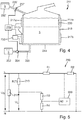
- FIG. 4 A third embodiment of a heating device 211 according to the invention is shown, which is designed as an evaporator.
- a heating device 211 For water 5 to be evaporated, it has a short upright pipe 213 corresponding to the fluid chamber, which has a circular cross section. Its diameter is larger than its height, but this can also vary significantly.
- a first heating element 217a is arranged all the way around or largely all the way around.
- a second heating element 217b of corresponding design On the outside of the tube 213 or its jacket side, a first heating element 217a is arranged all the way around or largely all the way around. Below this is arranged a second heating element 217b of corresponding design.
- the heating elements 217a and 217b can be similar to several heating conductors Fig. 3 with a horizontal parallel course.
- the heating elements 217a and 217b have a corresponding layer structure Fig.
- the heating elements 217a and 217b are connected to a controller 229.
- the dielectric insulation layers, not shown, are connected to a measuring device 230, which in turn is connected to the controller 229.
- the controller 229 can have or essentially consists of a controller, at least as far as the intelligent control functions are concerned. Above all, the controller 229 also controls the operation of the heating elements 217a and 217b, possibly independently of one another. With regard to the structure of the EP 3278691 A1 directed. Water 5 in the tube 213 is heated and evaporated by means of the heating elements 217a and 217b, so that the water vapor can escape from the heating device 211 at the top. As described there, temperature monitoring is of great importance, for which the invention also plays a role here due to the increased accuracy achieved.
- a relatively small calcification 239 is shown in simplified form at the top right. It has the effect that in this area the heating element 217a cannot give off its heat sufficiently well to the water 5 in the tube 213, so that an overheating mentioned at the beginning or a so-called hotspot can occur. This can be recognized particularly well with the detection of the temperature according to the invention.
- a water tank 232 is provided with a pump 234 controlled by the controller 239 in order to refill water 5 from the water tank 232 into the heating device 211 or into the fluid chamber of the pipe 213. This is done especially when it has been determined that the water level in tube 213 has dropped significantly. This is shown by the dashed line below the upper heating element 217a. At the latest then this upper heating element 217a will overheat considerably, and water must be topped up for an optimal function of the evaporation and above all for damage due to the overheating to prevent. This replenishment of water is then carried out by the controller 229 by means of the pump 234 when it has recognized the rising temperature.
- a further water tank 232 ' is shown with water 5 in the top left of the heating device 211. It is arranged above the tube 213, so that water can automatically flow into the tube 213 or the fluid chamber through a feed line 235 '.
- the control 229 can correspondingly open a valve 237 in the feed line 235 '.
- the measuring device 230 is shown in detail, which in turn is connected to the control 229 or the corresponding controller.
- the voltage U N is the line voltage and is applied to a single heating element 217, which is shown here. If there were several heating elements, they would probably be connected to the mains voltage U N in parallel with one another.
- the dielectric insulation layer is represented by the temperature-dependent resistor R (T) 219.
- the leakage voltage U L is present here with respect to ground N, since a corresponding leakage current flows out via the dielectric insulation layer.
- the two resistors R3 and R4 are provided as voltage dividers in the measuring device 230.
- the center tap goes directly to an AD input AD of the controller. This was explained at the beginning.
- a further voltage divider comprising resistors R1 and R2 is provided in order to tap the line voltage U N at phase L and also to pass it to an input of the controller of controller 229.
- the voltage dividers or a voltage divider network or resistance network formed thereby can also be designed differently.
- the leakage voltage U L is divided by the measured mains voltage U N , and this quotient is then advantageously multiplied by a compensation value.
- 230 is selected because the heating device 211 is to be operated with a mains voltage U N of 230 V. This gives you a standardized leak signal. This can then be evaluated with regard to its absolute value or with regard to its slope, that is to say the first derivative of the course. This is done with the 6 and 7 explained. Depending on which of the known overtemperature cases is recognized therefrom, water 5 can be refilled into the fluid chamber or the heating power of one of the heating elements 217 or all heating elements can be reduced or switched off.
- Fig. 6 it is shown over time t how the mains voltage U N and the leakage voltage U L dependent thereon run.
- the invention has not yet been implemented here.
- At the very bottom is shown corresponding to the right vertical axis as the activity state of the pump 234 corresponds Fig. 4 is whether water needs to be pumped in again.
- the operation of the evaporator with heating device 211 is such that something is briefly pumped every 28 seconds in order to refill water. This can be seen in the interval between 750 sec and 850 sec and from 890 sec.However, since there are jumps in the mains voltage U N , in particular if a further strong heating device of the baking oven is switched on or off as a consumer as a consumer when the heating device is arranged in an evaporator within a baking oven If the jumps are not negligible, an error occurs. These jumps up here occur at about 720 sec and about 860 sec. At about 805 sec and 950 sec the jumps occur downwards. This depends on switching the additional consumer on and off.
- the mains voltage U N fluctuates again, but at slightly different times. It can be seen that the detection and consideration of this fluctuation in the mains voltage U N at the heating device, which indeed influences the leakage voltage U L , can be compensated for in such a way that the pumping at the pump 234 takes place at the desired regular intervals. Above all, this can also be seen in the regularity of the course of the leakage voltage U L. If the jumps occur in the mains voltage U N , the leakage voltage U L does not change. This enables better temperature detection, and the heater 211 can also be operated better.
- This effect is easily imaginable, and is equally advantageous when recognizing, for example, a hotspot or local overheating by calcification 239 Fig. 4 ,
- This overheating causes the leakage voltage U L to increase , since an increased leakage current flows in this area.
- a sudden increase in the line voltage U N with which the heating element is operated and thus a corresponding jump in the leakage voltage inevitably occurs can be compensated for.
Abstract
Bei einem Verfahren zum Betrieb einer Heizeinrichtung wird zuerst Fluid in eine Fluidkammer eingefüllt, dann werden die Heizelemente der Heizeinrichtung eingeschaltet und ein Leckstrom als temperaturabhängiger Stromfluss durch eine dielektrische Isolationsschicht wird erfasst. Eine Versorgungsspannung der Heizeinrichtung wird gemessen und bei einer Auswertung der Temperatur an der Fluidkammer abhängig vom Leckstrom berücksichtigt. Der Leckstrom wird über einem Widerstand in eine Leckspannung umgewandelt, die dann durch die gemessene Versorgungsspannung dividiert wird. Anschließend kann der erhaltene Quotient mit einem Kompensationswert multipliziert werden, um ein normiertes Leck-Signal zu erhalten, das auf einen Grundwert der Versorgungsspannung normiert ist. Das normierte Leck-Signal wird genutzt, um bei Übersteigen eines bestimmten absoluten Wertes des Leck-Signals oder bei Übersteigen einer bestimmten Steigung des Verlaufs des Leck-Signals mehr Fluid in die Fluidkammer nachzufüllen und/oder die Heizleistung mindestens eines Heizelements zu reduzieren.In a method for operating a heating device, fluid is first filled into a fluid chamber, then the heating elements of the heating device are switched on and a leakage current as a temperature-dependent current flow through a dielectric insulation layer is detected. A supply voltage of the heating device is measured and taken into account when evaluating the temperature in the fluid chamber depending on the leakage current. The leakage current is converted into a leakage voltage via a resistor, which is then divided by the measured supply voltage. The quotient obtained can then be multiplied by a compensation value in order to obtain a standardized leak signal which is standardized to a basic value of the supply voltage. The standardized leak signal is used to refill more fluid into the fluid chamber and / or to reduce the heating power of at least one heating element if a certain absolute value of the leak signal is exceeded or if a certain slope of the course of the leak signal is exceeded.
Description
Die Erfindung betrifft eine Heizeinrichtung für Fluide, insbesondere für Flüssigkeiten wie Wasser, sowie ein Verfahren zum Betrieb einer solchen Heizeinrichtung, insbesondere bezüglich einer Temperaturerfassung oder Erfassung von temperaturabhängigen Vorgängen.The invention relates to a heating device for fluids, in particular for liquids such as water, and a method for operating such a heating device, in particular with regard to temperature detection or detection of temperature-dependent processes.
Aus der
Der Erfindung liegt die Aufgabe zugrunde, eine eingangs genannte Heizeinrichtung sowie ein Verfahren zu ihrem Betrieb zu schaffen, mit denen Probleme des Standes der Technik gelöst werden können und es insbesondere möglich ist, die Heizeinrichtung noch genauerer und noch sicherer betreiben zu können.The invention has for its object to provide a heating device mentioned above and a method for its operation with which problems of the prior art can be solved and in particular it is possible to operate the heating device even more precisely and safely.
Gelöst wird diese Aufgabe durch eine Heizeinrichtung mit den Merkmalen des Anspruchs 1 sowie durch ein Verfahren mit den Merkmalen des Anspruchs 10. Vorteilhafte sowie bevorzugte Ausgestaltungen der Erfindung sind Gegenstand der weiteren Ansprüche und werden im Folgenden näher erläutert. Dabei werden manche der Merkmale nur für die Heizeinrichtung oder nur für das Verfahren zu ihrem Betrieb beschrieben. Sie sollen jedoch unabhängig davon sowohl für die Heizeinrichtung als auch für das Verfahren zu ihrem Betrieb selbständig und unabhängig voneinander gelten können. Der Wortlaut der Ansprüche wird durch ausdrückliche Bezugnahme zum Inhalt der Beschreibung gemacht.This object is achieved by a heating device with the features of
Es ist vorgesehen, dass die Heizeinrichtung eine Fluidkammer aufweist. Diese kann unterschiedlich ausgebildet sein und als eine Art Fluidvorrat ausgebildet sein, alternativ im Wesentlichen für einen Durchlauf von Fluid, das erhitzt werden soll, beispielsweise als ein Kanal oder ein Rohr. An einer Außenseite der Fluidkammer, vorteilhaft vom Fluid abgewandt, ist mindestens ein Heizelement mit mindestens einem Heizleiter aufgebracht. Das Heizelement kann vielfältig ausgebildet sein und beispielsweise auch mehrere parallel und/oder seriell geschaltete Heizleiter aufweisen, wie dies an sich bekannt ist. Das Heizelement dient dazu, Fluid in der Fluidkammer zu erhitzen, beispielsweise Wasser, um es zu verdampfen.It is provided that the heating device has a fluid chamber. This can be designed differently and can be designed as a kind of fluid supply, alternatively essentially for a pass of fluid to be heated, for example as a channel or a pipe. At least one heating element with at least one heating conductor is applied to an outside of the fluid chamber, advantageously facing away from the fluid. The heating element can be of various designs and, for example, also have a plurality of heating conductors connected in parallel and / or in series, as is known per se. The heating element serves to heat fluid in the fluid chamber, for example water, in order to evaporate it.
Die Heizeinrichtung weist mindestens eine flächige dielektrische Isolationsschicht auf. Sie überdeckt im Wesentlichen das mindestens eine Heizelement bzw. überdeckt eine entsprechend große Fläche. Die Isolationsschicht kann direkt auf dem Heizelement aufgebracht sein, es können aber auch weitere Schichten dazwischenliegen. Des Weiteren weist die dielektrische Isolationsschicht einen temperaturabhängigen elektrischen Widerstand auf. Auf beiden Seiten der Isolationsschicht ist jeweils mindestens ein elektrisch leitfähiger Anschluss vorgesehen. Dies kann beispielsweise das Heizelement oder einer seiner Heizleiter sein, möglicherweise auch eine metallische Außenseite der Fluidkammer selbst, die vorteilhaft auch ein Träger für das Heizelement ist. Mindestens einer der elektrisch leitfähigen Anschlüsse kann flächig sein, vorteilhaft mit etwa derselben Fläche wie die Isolationsschicht. Insbesondere sind die beiden elektrisch leitfähigen Anschlüsse auf beiden Seiten der Isolationsschicht großflächig bzw. überdecken bzw. überlappen die Isolationsschicht.The heating device has at least one flat dielectric insulation layer. It essentially covers the at least one heating element or covers a correspondingly large area. The insulation layer can be applied directly to the heating element, but other layers can also be located in between. Furthermore, the dielectric insulation layer has a temperature-dependent electrical resistance. At least one electrically conductive connection is provided on each side of the insulation layer. This can be, for example, the heating element or one of its heating conductors, possibly also a metallic outside of the fluid chamber itself, which is advantageously also a carrier for the heating element. At least one of the electrically conductive connections can be flat, advantageously with approximately the same area as the insulation layer. In particular, the two electrically conductive connections on both sides of the insulation layer have a large area or cover or overlap the insulation layer.
Mindestens einer der elektrisch leitfähigen Anschlüsse ist an eine Steuerung bzw. an eine Messeinrichtung angeschlossen, um einen Leckstrom bzw. Ableitstrom als temperaturabhängigen Stromfluss durch die dielektrische Isolationsschicht hindurch zu erfassen. Auch dies ist für sich genommen aus dem vorgenannten Stand der Technik bekannt. Diese Steuerung weist Controller bzw. einen Mikrocontroller auf, der mindestens einen AD-Eingang aufweist. Des Weiteren sind Messmittel vorgesehen, um eine Versorgungsspannung der Heizeinrichtung zu messen. Diese Versorgungsspannung ist diejenige Spannung, an die die Heizeinrichtung angeschlossen ist bzw. mit der das mindestens eine Heizelement betrieben wird. Dies ist in der Regel die sogenannte Netzspannung, was jedoch nicht zwingend so sein muss. Die Messmittel können mindestens einen Widerstand oder ein Widerstands-Netzwerk als Spannungsteiler aufweisen, was nachfolgend noch näher erläutert wird. Des Weiteren sind die Messmittel mit dem AD-Eingang des Controllers verbunden, so dass der Controller die Information über die genaue Höhe der Versorgungsspannung erhält.At least one of the electrically conductive connections is connected to a controller or to a measuring device in order to detect a leakage current or leakage current as a temperature-dependent current flow through the dielectric insulation layer. This is also known per se from the aforementioned prior art. This controller has controllers or a microcontroller that has at least one AD input. Furthermore, measuring means are provided to measure a supply voltage of the heating device. This supply voltage is the voltage to which the heating device is connected or with which the at least one heating element is operated. This is usually the so-called mains voltage, but this does not necessarily have to be the case. The measuring means can have at least one resistor or a resistor network as a voltage divider, which will be explained in more detail below. Furthermore, the measuring devices are connected to the AD input of the controller, so that the controller receives information about the exact level of the supply voltage.
Somit ist es möglich, dass in der Steuerung bzw. in dem Controller nicht nur der temperaturabhängige Leckstrom erfasst wird, aus dem eben eine Temperatur an der Heizeinrichtung bzw. an der Fluidkammer ermittelt werden kann. Dies an sich ist aus dem eingangs genannten Stand der Technik ja bekannt. Es hat sich im Rahmen der Erfindung aber herausgestellt, dass hierbei Schwankungen der Versorgungsspannung stark störende Auswirkungen auf die Heizeinrichtung haben können, da die über der Isolationsschicht abfallende Leckspannung entsprechend dem Leckstrom direkt davon abhängt. Somit hängt auch der Leckstrom direkt von der Versorgungsspannung ab bzw. schwankt mit dieser. In der Steuerung kann es nun zu Problemen kommen, wenn Schwankungen des Leckstroms erfasst werden, da nicht erkannt werden kann, ob diese von Schwankungen in der Versorgungsspannung oder von einer Temperaturänderung kommen. Hierbei hat es sich beispielsweise als bereits sehr störend erwiesen, wenn in einem elektrischen Gerät, in dem die Heizeinrichtung eingebaut ist, andere starke elektrische Verbraucher ein- oder ausgeschaltet werden. Ist die Heizeinrichtung beispielsweise als Verdampfer in einem Dampfbackofen eingesetzt, der noch weitere elektrische Heizungen mit hoher Leistung aufweist, so kann ein im Betrieb vorgesehenes häufiges Ein- und Ausschalten dieser Heizeinrichtungen, beispielsweise als bestimmungsgemäßes Takten zum Halten einer Temperatur, zu Schwankungen in der Versorgungsspannung und somit zu Schwankungen des Leckstroms führen. Dies kann mit der Erfindung vermieden werden, wenn die Versorgungsspannung eben auch gemessen wird, da damit dann dieser Effekt sozusagen herausgerechnet werden kann.It is therefore possible that not only the temperature-dependent leakage current is recorded in the controller or in the controller, from which a temperature at the heating device or at the fluid chamber can be determined. This is in itself from the state mentioned at the beginning known to technology. It has been found within the scope of the invention, however, that fluctuations in the supply voltage can have highly disruptive effects on the heating device, since the leakage voltage dropping across the insulation layer depends directly on it in accordance with the leakage current. The leakage current therefore also depends directly on the supply voltage or fluctuates with it. Problems can now arise in the control system if fluctuations in the leakage current are detected, since it cannot be recognized whether these are caused by fluctuations in the supply voltage or by a change in temperature. Here, for example, it has already proven to be very disruptive when other strong electrical consumers are switched on or off in an electrical device in which the heating device is installed. If the heating device is used, for example, as an evaporator in a steam oven, which has other high-performance electrical heaters, frequent switching on and off of these heating devices during operation, for example as intended clocking for maintaining a temperature, for fluctuations in the supply voltage and thus lead to fluctuations in the leakage current. This can be avoided with the invention if the supply voltage is also measured, since this effect can then be calculated out, so to speak.
Es kann vorgesehen sein, dass die Messmittel einen Spannungsteiler mit mindestens zwei Widerständen aufweisen. Dieser Spannungsteiler kann mit einerseits der Versorgungsspannung verbunden sein, um diese zu verringern, so dass sie direkt mit dem AD-Eingang verbunden werden kann. Dies stellt eine sehr einfache Möglichkeit dar, wie der Controller die Information über die Versorgungsspannung erhalten kann.It can be provided that the measuring means have a voltage divider with at least two resistors. This voltage divider can be connected to the supply voltage in order to reduce it so that it can be connected directly to the AD input. This is a very simple way of how the controller can get the information about the supply voltage.
Vorteilhaft sind zwei AD-Eingänge vorgesehen, und zwar einer für die Versorgungsspannung und ein anderer für den Leckstrom bzw. Ableitstrom oder die entsprechende Spannung. Beide Werte können dann an AD-Eingängen des Controllers erfasst werden.Two AD inputs are advantageously provided, one for the supply voltage and another for the leakage current or leakage current or the corresponding voltage. Both values can then be recorded at the AD inputs of the controller.
Möglicherweise kann der Spannungsteiler auch als Spannungsteiler-Netzwerk ausgebildet sein und beispielsweise drei Widerstände aufweisen oder sogar noch mehr. Dabei können zwei Widerstände in Serie und ein Widerstand parallel dazu geschaltet sein. Hierfür können allgemein bekannte Möglichkeiten angewandt werden, die der Fachmann kennt.The voltage divider can possibly also be designed as a voltage divider network and, for example, have three resistors or even more. Two resistors can be connected in series and one resistor connected in parallel. For this, generally known possibilities can be used, which are known to the person skilled in the art.
In einer ersten vorteilhaften Ausgestaltung der Erfindung ist die Fluidkammer als ein Rohr ausgebildet, das aufrecht stehend oder liegend angeordnet sein kann. Möglicherweise kann es auch schräg verlaufen. Vorteilhaft ist mindestens ein Heizelement an einer Mantelwand des Rohrs angeordnet, möglicherweise auch ein Heizelement an seiner Unterseite.In a first advantageous embodiment of the invention, the fluid chamber is designed as a tube, which can be arranged upright or lying. It may also run at an angle. At least one heating element is advantageously arranged on a jacket wall of the tube, possibly also a heating element on its underside.
In einer anderen Ausgestaltung der Erfindung ist die Fluidkammer von beliebiger Form, beispielsweise auch als flache Schale, und weist nur an ihrer Unterseite ein Heizelement auf. Dann soll bezüglich einer Temperaturüberwachung vor allem erkannt und vermieden werden, dass kein zu verdampfendes Wasser mehr vorhanden ist, wodurch eine zu starke und zu schnelle Temperaturerhöhung mit möglicher Beschädigung der Heizeinrichtung eintreten könnte.In another embodiment of the invention, the fluid chamber is of any shape, for example also as a flat shell, and has a heating element only on its underside. Then, with regard to temperature monitoring, it should above all be recognized and avoided that there is no longer any water to be evaporated, as a result of which an excessive and rapid increase in temperature with possible damage to the heating device could occur.
In weiterer Ausgestaltung der Erfindung gemäß der ersten Alternative kann an der Außenseite der Fluidkammer, die ein aufrecht stehendes Rohr aufweist, mindestens ein Heizelement aufgebracht sein, vorteilhaft können zwei Heizelemente mit jeweils mehreren Heizleitern aufgebracht sein. Diese beiden Heizelemente können dann separat angesteuert werden. Sie sind vorteilhaft in getrennten Höhenabschnitten der Fluidkammer bzw. des Rohrs angeordnet, so dass eine von der Höhe abhängige unterschiedliche Beheizung möglich ist. Dabei kann ein zweites Heizelement über einem ersten Heizelement angeordnet sein. Hierbei kann eine genannte Temperaturerfassung nicht nur dazu dienen, lokale Überhitzungen an einem der Heizelemente festzustellen, wie sie durch Verkalkung entstehen können. Es kann auch festgestellt werden, ob zuerst an dem oberen zweiten Heizelement eine zu hohe Temperatur auftritt, bevor sie an dem unteren ersten Heizelement auftritt. Dies kann dann als Signal dafür gewertet werden, dass Fluid bzw. Wasser nachgefüllt werden muss zum Verdampfen. Durch eine langfristige Temperaturerhöhung über mehrere Minuten oder sogar mehrere Stunden des Betriebs hinweg kann eine großflächige Verkalkung erkannt werden, da dann die von dem Heizelement erzeugte Wärme nicht mehr so gut an das Fluid in der Fluidkammer abgegeben werden kann.In a further embodiment of the invention according to the first alternative, at least one heating element can be applied to the outside of the fluid chamber, which has an upright tube, advantageously two heating elements, each with a plurality of heating conductors, can be applied. These two heating elements can then be controlled separately. They are advantageously arranged in separate height sections of the fluid chamber or the tube, so that different heating depending on the height is possible. A second heating element can be arranged above a first heating element. In this case, a temperature measurement mentioned can not only serve to determine local overheating on one of the heating elements, as can occur due to calcification. It can also be determined whether too high a temperature occurs first on the upper second heating element before it occurs on the lower first heating element. This can then be interpreted as a signal that fluid or water has to be refilled to evaporate. Large-scale calcification can be recognized by a long-term increase in temperature over several minutes or even several hours of operation, since the heat generated by the heating element can then no longer be given off to the fluid in the fluid chamber as well.
In weiterer Ausgestaltung der Erfindung kann vorgesehen sein, dass die Heizeinrichtung eine Pumpe aufweist, mit der Fluid in die Fluidkammer gepumpt werden kann. Diese Pumpe ist von der Steuerung ansteuerbar, gerade in einem vorgenannten Fall, wenn erkannt wird, dass ein unerwarteter Temperaturanstieg vorliegt, weil nicht mehr genügend Fluid zur Beheizung da ist und deswegen die Temperatur zu stark ansteigt. Alternativ zu einer solchen Pumpe kann ein höher gelegener Wassertank vorgesehen sein mit einer Zuleitung zu der Fluidkammer mit einem Ventil darin, das von der Steuerung entsprechend angesteuert werden kann, um weiteres Wasser in die Fluidkammer einzulassen.In a further embodiment of the invention it can be provided that the heating device has a pump with which fluid can be pumped into the fluid chamber. This pump can be controlled by the control, especially in the aforementioned case, when it is recognized that there is an unexpected rise in temperature because there is no longer enough fluid for heating and the temperature therefore rises too much. As an alternative to such a pump, a water tank located at a higher level can be provided with a feed line to the fluid chamber with a valve therein, which can be controlled accordingly by the control in order to admit further water into the fluid chamber.
Eine Möglichkeit des erfindungsgemäßen Verfahrens ist es also, Fluid in die Fluidkammer einzufüllen bzw. in ausreichender Menge in der Fluidkammer zu halten. Dies kann stationär erfolgen oder auch im Durchfluss. Dann wird mindestens eines der Heizelemente eingeschaltet zum Aufheizen der Fluidkammer und des Fluids darin. Vorteilhaft können alle Heizelemente der Heizeinrichtung eingeschaltet werden. Der Leckstrom als temperaturabhängiger Stromfluss durch die dielektrische Isolationsschicht wird erfasst. Dies kann grundsätzlich beliebig erfolgen, vorteilhaft eben über einem Widerstand als Leckspannung, da diese leichter an einen AD-Anschluss des eingangs genannten Controllers gegeben werden kann. Schließlich wird die Versorgungsspannung der Heizeinrichtung gemessen und diese gemessene Versorgungsspannung bei der Auswertung der Temperatur, die von dem Leckstrom abhängt, berücksichtigt. So kann ein Einfluss von Schwankungen dieser Versorgungsspannung reduziert werden oder sogar möglichst ganz beseitigt werden.One possibility of the method according to the invention is therefore to fill fluid into the fluid chamber or to keep it in sufficient quantity in the fluid chamber. This can be done stationary or in flow. Then at least one of the heating elements is turned on to heat the fluid chamber and the fluid therein. All heating elements of the heating device can advantageously be switched on. The leakage current as a temperature-dependent current flow through the dielectric insulation layer is recorded. In principle, this can be done arbitrarily, advantageous just above a resistor as leakage voltage, since this can be more easily given to an AD connection of the above-mentioned controller. Finally, the supply voltage of the heating device is measured and this measured supply voltage is taken into account when evaluating the temperature, which depends on the leakage current. In this way, the influence of fluctuations in this supply voltage can be reduced or even eliminated as far as possible.
Vorteilhaft kann aus der gemessenen Versorgungsspannung und dem erfassten Leckstrom ein normiertes Leck-Signal in der Steuerung bzw. in einem Controller der Steuerung berechnet werden. Damit kann beispielsweise ein Nachfüllen von Fluid in die Fluidkammer beeinflusst werden. Ebenso kann eine Ansteuerung der Heizelemente berücksichtigt werden, insbesondere mit Leistungsreduzierung oder zumindest teilweiser Abschaltung.A standardized leak signal in the controller or in a controller of the controller can advantageously be calculated from the measured supply voltage and the detected leakage current. A refilling of fluid into the fluid chamber can thus be influenced, for example. Control of the heating elements can also be taken into account, in particular with power reduction or at least partial shutdown.
Eine Temperatur kann überwacht werden durch Auswerten des Leckstroms hinsichtlich seiner absoluten Höhe und/oder seiner Steigung. Somit kann er sozusagen im kurzzeitigen wie auch im längerfristigen Verlauf ausgewertet werden. Auch dies ist an sich aus dem eingangs genannten Stand der Technik bekannt.A temperature can be monitored by evaluating the leakage current with regard to its absolute height and / or its slope. Thus, it can be evaluated in a short-term as well as in the long-term course, so to speak. This is also known per se from the prior art mentioned at the outset.
In vorteilhafter Ausgestaltung der Erfindung ist es möglich, dass der Leckstrom über einem Widerstand eben in eine Leckspannung umgewandelt wird. Diese Leckspannung kann direkt an einen AD-Eingang der Steuerung gegeben werden zur weiteren Verarbeitung. In der Steuerung bzw. in dem Controller mit dem AD-Eingang wird die umgewandelte Leckspannung durch die gemessene Versorgungsspannung dividiert, die ebenfalls auf vorgenannte Art und Weise an den Controller gegeben werden kann. Anschließend kann vorteilhaft der erhaltene Quotient mit einem Kompensationswert multipliziert werden, um ein normiertes Leck-Signal zu erhalten, was aber nicht zwingender Bestandteil der Erfindung sein muss. Dieses ist dann eben auf einen Grundwert der Versorgungsspannung normiert. Der Kompensationswert kann beispielsweise 230 betragen bei einer grundsätzlichen Versorgungsspannung von 230 V. Der vorgenannte Quotient bzw. das normierte Leck-Signal werden dann genutzt, um bei Übersteigen eines bestimmten absoluten Werts des Leck-Signals oder bei Übersteigen einer bestimmten Steigung des Verlaufs des Leck-Signals mehr Fluid bzw. Wasser in die Fluidkammer nachzufüllen und/oder um die Heizleistung der Heizelemente zu reduzieren und/oder um einen Verkalkungsgrad in der Fluidkammer zu erkennen. So kann der Rechenvorgang leicht durchgeführt werden mit verringertem Aufwand.In an advantageous embodiment of the invention, it is possible for the leakage current to be converted into a leakage voltage via a resistor. This leakage voltage can be sent directly to an AD input of the control for further processing. In the controller or in the controller with the AD input, the converted leakage voltage is divided by the measured supply voltage, which can also be passed to the controller in the aforementioned manner. The quotient obtained can then advantageously be multiplied by a compensation value in order to obtain a standardized leak signal, which, however, need not be an integral part of the invention. This is then standardized to a basic value of the supply voltage. The compensation value can be 230, for example, with a basic supply voltage of 230 V. The aforementioned quotient or the standardized leak signal are then used to determine if the leak signal exceeds a certain absolute value or if the slope of the leak exceeds a certain slope. Signal to refill more fluid or water in the fluid chamber and / or to reduce the heating power of the heating elements and / or to detect a degree of calcification in the fluid chamber. So the calculation process can be carried out easily with reduced effort.
In einer Möglichkeit der Erfindung kann in dem Fall, dass das normierte Leck-Signal einen ersten Grenzwert übersteigt als Zeichen einer zu hohen Temperatur, eben mehr Fluid in die Fluidkammer nachgefüllt werden. Dieses Nachfüllen kann dann gestoppt werden, wenn das normierte Leck-Signal den ersten Grenzwert wieder unterschritten hat. Dann ist die Temperatur durch das nachgefüllte Fluid wieder unter den Grenzwert entsprechend einer bestimmten kritischen Temperatur gesunken.In one possibility of the invention, in the event that the standardized leak signal exceeds a first limit value as a sign of an excessively high temperature, more fluid can enter the Fluid chamber to be refilled. This refilling can then be stopped when the standardized leak signal has fallen below the first limit value again. Then the temperature has dropped again below the limit value corresponding to a certain critical temperature due to the refilled fluid.
In ähnlicher Form kann in dem Fall, dass die Steigung des Verlaufs des normierten Leck-Signals einen zweiten Grenzwert übersteigt, dies als Zeichen eines zu starken Temperaturanstiegs gewertet werden. Dann kann ebenfalls mehr Fluid in die Fluidkammer nachgefüllt werden. Auch hier wird das Nachfüllen gestoppt, wenn die Steigung des Verlaufs des normierten Leck-Signals den zweiten Grenzwert wieder unterschritten hat. So kann bei einem Verdampfer als Heizeinrichtung entsprechend der
Diese und weitere Merkmale gehen außer aus den Ansprüchen auch aus der Beschreibung und den Zeichnungen hervor, wobei die einzelnen Merkmale jeweils für sich allein oder zu mehreren in Form von Unterkombinationen bei einer Ausführungsform der Erfindung und auf anderen Gebieten verwirklicht sein und vorteilhafte sowie für sich schutzfähige Ausführungen darstellen können, für die hier Schutz beansprucht wird. Die Unterteilung der Anmeldung in einzelne Abschnitte sowie Zwischen-Überschriften beschränken die unter diesen gemachten Aussagen nicht in ihrer Allgemeingültigkeit.These and further features emerge from the claims and also from the description and the drawings, the individual features being realized individually or in groups in the form of sub-combinations in one embodiment of the invention and in other fields and being advantageous and capable of being protected by themselves Can represent versions for which protection is claimed here. The division of the application into individual sections and subheadings do not limit the general validity of the statements made under these.
Ausführungsbeispiele der Erfindung sind in den Zeichnungen schematisch dargestellt und werden im Folgenden näher erläutert. In den Zeichnungen zeigen:
- Fig. 1
- eine erste Ausführung einer erfindungsgemäßen Heizeinrichtung mit einem einzigen Heizelement mit Schichtaufbau in Explosionsdarstellung,
- Fig. 2
- eine zweite Ausführung einer erfindungsgemäßen Heizeinrichtung mit zwei Heizelementen in seitlicher Darstellung,
- Fig. 3
- eine Draufsicht auf die Heizeinrichtung aus
Fig. 2 , - Fig. 4
- eine dritte Ausführung einer erfindungsgemäßen Heizeinrichtung als aufrecht stehende Rohr mit zwei Heizelementen,
- Fig. 5
- eine vereinfachte Darstellung des Aufbaus der Messeinrichtung mit Spannungsteilern aus Widerständen,
- Fig. 6
- ein Diagramm mit Verläufen der Netzspannung, der Leckspannung und des Betriebs der Pumpe aus
Fig. 4 ohne die Erfindung und - Fig. 7
- das Diagramm mit Verläufen der Netzspannung, der Leckspannung und des Betriebs der Pumpe entsprechend
Fig. 6 mit der Erfindung.
- Fig. 1
- a first embodiment of a heating device according to the invention with a single heating element with a layer structure in an exploded view,
- Fig. 2
- a second embodiment of a heating device according to the invention with two heating elements in a side view,
- Fig. 3
- a top view of the heater
Fig. 2 . - Fig. 4
- a third embodiment of a heating device according to the invention as an upright tube with two heating elements,
- Fig. 5
- a simplified representation of the construction of the measuring device with voltage dividers from resistors,
- Fig. 6
- a diagram with curves of the mains voltage, the leakage voltage and the operation of the pump
Fig. 4 without the invention and - Fig. 7
- the diagram with curves of the mains voltage, the leakage voltage and the operation of the pump accordingly
Fig. 6 with the invention.
In
Auf der ersten Isolationsschicht 15 ist ein einziges Heizelement 17 mit mäanderförmigem Verlauf aufgebracht, das aus einzelnen hintereinander bzw. seriell geschalteten Heizleitern 17' besteht. Diese sind weitgehend gerade und durch gebogene Abschnitte verbunden. Es könnte aber auch ein einziger Heizleiter vorgesehen sein, der auch erheblich breiter ist als die hier dargestellten schmalen Heizleiter 17', siehe hierzu auch die
Über dem Heizelement 17 ist großflächig eine dielektrische Isolationsschicht 20 aufgebracht, die glasartig bzw. eine Glasschicht sein kann. Die dielektrische Isolationsschicht 20 verschließt sozusagen die Heizeinrichtung 11 bzw. isoliert das Heizelement 17 und verschließt dieses sowie den Schichtaufbau, insbesondere gegen schädliche oder aggressive Umwelteinflüsse. Zur elektrischen Kontaktierung an das Heizelement 17 bzw. dessen Heizleiterkontakte 18 weist die dielektrische Isolationsschicht 20 Fenster 21 genau über den Heizleiterkontakten 18 auf für ein an sich bekanntes Durchkontaktieren.A
Auf der dielektrischen Isolationsschicht 20 ist eine Elektrode 24 als elektrisch leitfähiger Anschluss aufgebracht, und zwar in Form einer großflächigen Schicht. Diese ist hier genau so groß wie der Träger 13 und die Isolationsschicht 15. Die Elektrode 24 sollte nicht direkt auf den Träger 13 oder das Heizelement 17 überlappen, da sie von Träger 13 und Heizelement 17 isoliert sein muss. Auf der Elektrode 24 kann sich eine weitere Abdeckung bzw. Isolationsschicht befinden, muss aber nicht. Sie weist an den Ecken zwei Ausschnitte 25 auf, die zusammen mit den darunterliegenden Fenstern 21 in der dielektrischen Isolationsschicht 20 eine zuvor beschriebene Kontaktierung an die Heizleiterkontakte 18 ermöglichen. Das Heizelement 17 bzw. dessen Heizleiter 17' bilden die andere bzw. erste Anschlussfläche.An
Dargestellt ist auch eine Steuerung 29 mit Leistungsversorgung für das Heizelement 17. Des Weiteren ist eine Messeinrichtung 30 dargestellt, die einerseits mit der Elektrode 24 über einen Elektrodenkontakt 26 und andererseits mit dem Heizelement 17 verbunden ist. Wie zuvor erläutert worden ist, ändern sich die dielektrischen bzw. resistiven Eigenschaften der dielektrischen Isolationsschicht 20 mit der Temperatur, und der von der Messeinrichtung 30 erfasste Leckstrom bzw. Ableitstrom ändert sich entsprechend bzw. steigt an mit ansteigender Temperatur. Die Messeinrichtung erfasst dann diese Änderung der Eigenschaften der dielektrischen Isolationsschicht 20 zwischen Heizelement 17 und Elektrode 24.A
In
An der Mediumseite 113 besteht die Gefahr einer Verkalkung der Heizeinrichtung 111 mit den genannten Risiken einer Überhöhung der Temperatur und Beschädigung oder sogar Zerstörung einzelner Heizelemente 117 oder der Heizeinrichtung 111. Deswegen ist gerade bei den hier genannten hohen Leistungsdichten darauf zu achten, dass dies nicht passiert.On the
An die Heizeinrichtung 111 sind entsprechend der
In der
Beide Heizelemente 117a und 117b weisen die gleiche Länge und jeweils vier Längsabschnitte auf. Beide Heizelemente 117a und 117b weisen auch an zwei nebeneinanderliegenden Längsabschnitten auf bekannte Art und Weise Unterbrechungen durch Kontaktbrücken auf. Damit kann lokal die Heizleistung etwas gesenkt werden. Eine elektrische Kontaktierung der Heizelemente 117a und 117b erfolgt über die einzelnen Kontaktfelder 118a und 118b sowie ein gemeinsames Kontaktfeld 118'. Schematisch zu erkennen ist auch ein Steckanschluss 122, der auf den Kontaktfeldern 118 bzw. auf den Träger 112 aufgebracht ist, vorteilhaft gemäß der
Auf die Heizelemente 117a und 117b ist eine einzige flächige dielektrische Isolationsschicht 119 aus einem geeigneten Material aufgebracht, hier dargestellt durch die Kreuzschraffierung. Sie überdeckt beide Heizelemente 117a und 117b vollständig und reicht bis an den Rand des Trägers 112 oder kurz davor.A single flat
Auf die dielektrische Isolationsschicht 119 wiederum ist eine Elektrodenfläche 121 als elektrisch leitfähiger Anschluss aufgebracht, und zwar hier als vollflächige Elektrode. Somit ist zwar keine separate Temperaturerfassung bzw. Erfassung einer Verkalkung möglich mit Unterscheidung in verschiedene Flächen, aber ein einfacher Aufbau gewährleistet. Die flächenmäßige Unterscheidung erfolgt ja durch den vorbeschriebenen getrennten einzelnen Betrieb der Heizelemente 117a und 117b. Die Elektrodenfläche 121 ist auf hier nicht dargestellte Art und Weise elektrisch kontaktiert, vorteilhaft mittels des Steckanschlusses 122.In turn, an
In der
An der Innenseite des Rohrs 213 ist rechts oben eine relativ kleine Verkalkung 239 vereinfacht dargestellt. Sie bewirkt, dass in diesem Bereich das Heizelement 217a seine Wärme nicht ausreichend gut an das Wasser 5 im Rohr 213 abgeben kann, somit kann es hier zu einer eingangs genannten Überhitzung bzw. zu einem sogenannten Hotspot kommen. Dies kann mit der Erfassung der Temperatur gemäß der Erfindung besonders gut erkannt werden.On the inside of the
In der Heizeinrichtung 211 gemäß
Alternativ ist links oben an der Heizeinrichtung 211 ein weitere Wassertank 232' dargestellt mit Wasser 5 darin. Er ist oberhalb des Rohrs 213 angeordnet, so dass durch eine Zuleitung 235' Wasser selbsttätig in das Rohr 213 bzw. die Fluidkammer einströmen kann. Hierzu kann die Steuerung 229 entsprechend ein Ventil 237 in der Zuleitung 235' öffnen.Alternatively, a further water tank 232 'is shown with
In
Ein weiterer Spannungsteiler aus dem Widerständen R1 und R2 ist vorgesehen, um die Netzspannung UN an der Phase L abzugreifen und ebenfalls an einen Eingang des Controllers der Steuerung 229 zu geben. Selbstverständlich ist hier leicht vorstellbar, dass die Spannungsteiler bzw. ein dadurch gebildetes Spannungsteiler-Netzwerk oder Widerstands-Netzwerk auch anders ausgebildet sein können.A further voltage divider comprising resistors R1 and R2 is provided in order to tap the line voltage U N at phase L and also to pass it to an input of the controller of
In der Steuerung 229 wird dann anhand der eingelesenen Spannungssignale die zuvor beschriebene Berechnung durchgeführt. Insbesondere wird die Leckspannung UL durch die gemessene Netzspannung UN dividiert, und dieser Quotient wird dann vorteilhaft mit einem Kompensationswert multipliziert. Dieser ist hierzu 230 gewählt, da die Heizeinrichtung 211 mit einer Netzspannung UN von 230 V betrieben werden soll. So erhält man ein normiertes Leck-Signal. Dieses kann dann ausgewertet werden hinsichtlich seines absoluten Werts oder hinsichtlich seiner Steigung, also der ersten Ableitung des Verlaufs. Dies wird nachfolgend mit den
In der
Eigentlich ist der Betrieb des Verdampfers mit Heizeinrichtung 211 so, dass etwas alle 28 sec kurzzeitig gepumpt wird, um Wasser nachzufüllen. Dies zeigt sich in dem Intervall zwischen 750 sec und 850 sec sowie ab 890 sec. Da jedoch in der Netzspannung UN Sprünge auftreten, insbesondere wenn bei Anordnung der Heizeinrichtung in einem Verdampfer innerhalb eines Backofens eine weitere starke Heizeinrichtung des Backofens als Verbraucher eingeschaltet oder ausgeschaltet wird, wobei die Sprünge durchaus nicht vernachlässigbar sind, entsteht ein Fehler. Diese Sprünge nach oben treten hier auf bei etwa 720 sec und etwa 860 sec. Bei etwa 805 sec und 950 sec treten die Sprünge nach unten auf. Dies hängt eben vom Einschalten und Ausschalten des weiteren Verbrauchers ab. Es zeigt sich, dass je nach den Sprüngen der Netzspannung UN nach oben die Pumpe 234 anspringt, und zwar eben zum Zeitpunkt von etwas über 720 sec und etwas über 860 sec. Hier wird also zu früh gepumpt. Dies weist vor allem den Nachteil auf, dass dann mehr Fluid in der Heizeinrichtung ist als eigentlich notwendig oder vorgesehen, so dass mehr Wasser erhitzt werden muss und das Verdampfen etwas verschlechtert werden kann. Es ist auch zu erkennen, dass gerade an diesen Sprüngen das relativ regelmäßige Muster der Leckspannung UL unterbrochen ist. Dies führt ja gerade zum ungewünschten Pumpen, ohne dass es eigentlich notwendig wäre.Actually, the operation of the evaporator with
In der
Dieser Effekt ist leicht vorstellbar genauso vorteilhaft bei der Erkennung beispielsweise eines Hotspots bzw. einer lokalen Überhitzung durch eine Verkalkung 239 entsprechend
Ähnliches gilt für eine großflächige Verkalkung, die ein insgesamt langsames Ansteigen der Leckspannung aufgrund langsam ansteigender Temperatur bewirkt.The same applies to large-scale calcification, which causes the leakage voltage to rise slowly overall due to the slowly rising temperature.
Claims (15)
Applications Claiming Priority (1)
| Application Number | Priority Date | Filing Date | Title |
|---|---|---|---|
| DE102018213869.9A DE102018213869B4 (en) | 2018-08-17 | 2018-08-17 | Heating device and method for operating a heating device |
Publications (2)
| Publication Number | Publication Date |
|---|---|
| EP3614797A1 true EP3614797A1 (en) | 2020-02-26 |
| EP3614797B1 EP3614797B1 (en) | 2022-04-20 |
Family
ID=67514288
Family Applications (1)
| Application Number | Title | Priority Date | Filing Date |
|---|---|---|---|
| EP19188759.5A Active EP3614797B1 (en) | 2018-08-17 | 2019-07-29 | Heating device and method for operating a heating device |
Country Status (6)
| Country | Link |
|---|---|
| US (1) | US11585574B2 (en) |
| EP (1) | EP3614797B1 (en) |
| KR (1) | KR20200020642A (en) |
| CN (1) | CN110836532B (en) |
| DE (1) | DE102018213869B4 (en) |
| PL (1) | PL3614797T3 (en) |
Families Citing this family (2)
| Publication number | Priority date | Publication date | Assignee | Title |
|---|---|---|---|---|
| DE102020207784A1 (en) * | 2020-06-23 | 2021-12-23 | E.G.O. Elektro-Gerätebau GmbH | Heating device with a temperature measuring device and method for temperature measurement on the heating device and for production |
| CN112462824A (en) * | 2020-11-12 | 2021-03-09 | 宣城睿晖宣晟企业管理中心合伙企业(有限合伙) | Heating control system and method for thin film deposition equipment |
Citations (8)
| Publication number | Priority date | Publication date | Assignee | Title |
|---|---|---|---|---|
| EP1152639A2 (en) | 2000-05-03 | 2001-11-07 | E.G.O. Elektro-Gerätebau GmbH | Electrical heating unit, particularly for liquid supports |
| WO2010008279A1 (en) * | 2008-07-15 | 2010-01-21 | Otter Controls Limited | Heating element and method for operating such a heating element |
| DE102010043727A1 (en) | 2010-11-10 | 2012-05-10 | E.G.O. Elektro-Gerätebau GmbH | pump |
| DE102013200277A1 (en) | 2013-01-10 | 2014-01-30 | E.G.O. Elektro-Gerätebau GmbH | Heating device has measuring device that is connected to planar electrode and heating conductor, for detecting temperature dependent current flow between heating conductor and covering layer and/or dielectric insulation layer |
| EP3096585A1 (en) | 2015-05-18 | 2016-11-23 | E.G.O. ELEKTRO-GERÄTEBAU GmbH | Heating device for heating fluids and a method for operating such a heating device |
| EP3145273A1 (en) | 2015-09-21 | 2017-03-22 | E.G.O. ELEKTRO-GERÄTEBAU GmbH | Heating device for heating water and a method for operating such a heating device |
| EP3197241A1 (en) * | 2016-01-19 | 2017-07-26 | E.G.O. ELEKTRO-GERÄTEBAU GmbH | Heating device and method for measuring the temperature on the heating element |
| EP3278691A1 (en) | 2016-08-02 | 2018-02-07 | E.G.O. ELEKTRO-GERÄTEBAU GmbH | Evaporator device for water and cooking device with same |
Family Cites Families (21)
| Publication number | Priority date | Publication date | Assignee | Title |
|---|---|---|---|---|
| US4092520A (en) * | 1976-12-16 | 1978-05-30 | Baxter Travenol Laboratories, Inc. | Leakage current thermostat |
| JP2652430B2 (en) * | 1988-10-21 | 1997-09-10 | 松下電工株式会社 | Multi-division heat-sensitive sheet heating element |
| CN2056983U (en) | 1989-05-18 | 1990-05-09 | 陈非 | Full-automatic electrothermic shower |
| DE19612170A1 (en) * | 1996-03-27 | 1997-10-02 | Patent Treuhand Ges Fuer Elektrische Gluehlampen Mbh | Circuit arrangement for operating electric lamps and operating methods for electric lamps |
| JPH10247579A (en) * | 1997-03-05 | 1998-09-14 | Furukawa Electric Co Ltd:The | Electric heater |
| ES2191346T3 (en) * | 1997-12-02 | 2003-09-01 | Koninkl Philips Electronics Nv | HEATING CONTAINER AND METHOD OF CONTROL OF THE HEATING ELEMENT OF A CONTAINER OF THIS TYPE. |
| IT1306477B1 (en) * | 1998-10-13 | 2001-06-11 | Hydor Srl | THERMOSTATIC HEATER DEVICE FOR LIQUIDS, IN PARTICULAR FOR AQUARIUM WATER. |
| NL1014601C2 (en) | 2000-03-10 | 2001-09-11 | Ferro Techniek Bv | Heating element, liquid container and method for detecting temperature changes. |
| JP2004281121A (en) | 2003-03-13 | 2004-10-07 | Sanyo Electric Co Ltd | Ground-fault interrupter |
| NL1027571C2 (en) | 2004-11-23 | 2006-05-24 | Ferro Techniek Holding Bv | Email composition for use as a dielectric, and use of such an email composition. |
| DE502005004134D1 (en) | 2005-09-23 | 2008-06-26 | Catem Gmbh & Co Kg | Heat generating element of a heating device |
| US7256372B2 (en) | 2005-12-07 | 2007-08-14 | Aos Holding Company | Fluid-heating apparatus, circuit for heating a fluid, and method of operating the same |
| NL2000081C2 (en) | 2006-05-23 | 2007-11-26 | Ferro Techniek Holding Bv | Electric heating device with temperature detection by dielectric layer. |
| US7576305B2 (en) | 2006-09-22 | 2009-08-18 | Catem Gmbh & Co. Kg | Heat-generating element of a heating device |
| US8378271B2 (en) | 2007-07-11 | 2013-02-19 | International Business Machines Corporation | Utilization of overvoltage and overcurrent compensation to extend the usable operating range of electronic devices |
| KR100965302B1 (en) | 2008-05-06 | 2010-06-22 | 중앙제어 주식회사 | A apparatus for sensing a water leakage |
| JP2011058962A (en) * | 2009-09-10 | 2011-03-24 | Kurimoto Ltd | Method of measuring material temperature in direct resistance heater using rectifier-type dc power supply and measuring instrument therefor |
| JP5349653B2 (en) | 2012-06-13 | 2013-11-20 | 三菱電機株式会社 | Induction heating cooker |
| DE102012213385A1 (en) * | 2012-07-30 | 2014-05-22 | E.G.O. Elektro-Gerätebau GmbH | Heating and electrical appliance with heating device |
| DE102013201903A1 (en) * | 2013-02-06 | 2014-08-07 | E.G.O. Elektro-Gerätebau GmbH | Heat pump device, use of a pump with heatable pumping chamber in a heat pump device and method of operating a heat pump device |
| US10117292B2 (en) | 2013-04-19 | 2018-10-30 | Chromalox, Inc. | Medium voltage heater elements moisture detection circuit |
-
2018
- 2018-08-17 DE DE102018213869.9A patent/DE102018213869B4/en active Active
-
2019
- 2019-07-29 EP EP19188759.5A patent/EP3614797B1/en active Active
- 2019-07-29 PL PL19188759.5T patent/PL3614797T3/en unknown
- 2019-08-15 US US16/541,246 patent/US11585574B2/en active Active
- 2019-08-16 KR KR1020190100481A patent/KR20200020642A/en unknown
- 2019-08-19 CN CN201910763938.1A patent/CN110836532B/en active Active
Patent Citations (8)
| Publication number | Priority date | Publication date | Assignee | Title |
|---|---|---|---|---|
| EP1152639A2 (en) | 2000-05-03 | 2001-11-07 | E.G.O. Elektro-Gerätebau GmbH | Electrical heating unit, particularly for liquid supports |
| WO2010008279A1 (en) * | 2008-07-15 | 2010-01-21 | Otter Controls Limited | Heating element and method for operating such a heating element |
| DE102010043727A1 (en) | 2010-11-10 | 2012-05-10 | E.G.O. Elektro-Gerätebau GmbH | pump |
| DE102013200277A1 (en) | 2013-01-10 | 2014-01-30 | E.G.O. Elektro-Gerätebau GmbH | Heating device has measuring device that is connected to planar electrode and heating conductor, for detecting temperature dependent current flow between heating conductor and covering layer and/or dielectric insulation layer |
| EP3096585A1 (en) | 2015-05-18 | 2016-11-23 | E.G.O. ELEKTRO-GERÄTEBAU GmbH | Heating device for heating fluids and a method for operating such a heating device |
| EP3145273A1 (en) | 2015-09-21 | 2017-03-22 | E.G.O. ELEKTRO-GERÄTEBAU GmbH | Heating device for heating water and a method for operating such a heating device |
| EP3197241A1 (en) * | 2016-01-19 | 2017-07-26 | E.G.O. ELEKTRO-GERÄTEBAU GmbH | Heating device and method for measuring the temperature on the heating element |
| EP3278691A1 (en) | 2016-08-02 | 2018-02-07 | E.G.O. ELEKTRO-GERÄTEBAU GmbH | Evaporator device for water and cooking device with same |
Also Published As
| Publication number | Publication date |
|---|---|
| CN110836532A (en) | 2020-02-25 |
| DE102018213869A1 (en) | 2020-02-20 |
| US11585574B2 (en) | 2023-02-21 |
| EP3614797B1 (en) | 2022-04-20 |
| KR20200020642A (en) | 2020-02-26 |
| PL3614797T3 (en) | 2022-09-12 |
| CN110836532B (en) | 2023-03-10 |
| DE102018213869B4 (en) | 2020-03-05 |
| US20200056811A1 (en) | 2020-02-20 |
Similar Documents
| Publication | Publication Date | Title |
|---|---|---|
| EP3145273B1 (en) | Heating device for heating water and a method for operating such a heating device | |
| EP3088800B1 (en) | Heating device for heating liquids, evaporator for an electric cooking apparatus and method for operating a heating device | |
| EP2693835B1 (en) | Heating device and electric device with a heating device | |
| EP1152639B1 (en) | Electrical heating unit, particularly for liquid supports | |
| EP3278691B1 (en) | Evaporator device for water and cooking device with same | |
| EP3096585B1 (en) | Heating device for heating fluids and a method for operating such a heating device | |
| EP1870641B1 (en) | Vaporiser device and method for operating the vaporiser device | |
| EP3100014B1 (en) | Temperature measurement on a surface heater for a household appliance | |
| EP3614797B1 (en) | Heating device and method for operating a heating device | |
| EP2793008B1 (en) | Calibrator for calibration of temperature measuring devices | |
| EP3250003A1 (en) | Heating device | |
| EP2840404B1 (en) | Electrical bare element continuous flow heater and method for controlling the same | |
| EP3197241B1 (en) | Heating device and method for measuring the temperature on the heating element | |
| DE3512659A1 (en) | Heater for electrically operated hot-water apparatuses | |
| WO2009027042A1 (en) | Heating device, method for operating a heating device and electric heating apparatus of such a heating device | |
| EP3637948B1 (en) | Heating device and method for detecting temperature on a heating device | |
| DE2343833A1 (en) | Electric hot-plate - has a glass-like or ceramic plate with at least one heater below it pressed to the plate | |
| DE60118378T2 (en) | TUBULAR HEATING ELEMENT | |
| DE102018212094A1 (en) | Heating device for a hob and hob | |
| DE102018203609B4 (en) | Method and device for detecting a temperature on a heating element | |
| DE19934319A1 (en) | Heater with lye temperature control | |
| DE102015218121A1 (en) | Heating device for heating water and method for operating such a heater | |
| EP3771287A1 (en) | Radiation heating device and hob with such a radiation heating device | |
| DE102015218120B4 (en) | Method for operating a heating device for heating water, heating device and dishwasher | |
| DE102015205496A1 (en) | Heating liquid in a household appliance |
Legal Events
| Date | Code | Title | Description |
|---|---|---|---|
| PUAI | Public reference made under article 153(3) epc to a published international application that has entered the european phase |
Free format text: ORIGINAL CODE: 0009012 |
|
| STAA | Information on the status of an ep patent application or granted ep patent |
Free format text: STATUS: THE APPLICATION HAS BEEN PUBLISHED |
|
| AK | Designated contracting states |
Kind code of ref document: A1 Designated state(s): AL AT BE BG CH CY CZ DE DK EE ES FI FR GB GR HR HU IE IS IT LI LT LU LV MC MK MT NL NO PL PT RO RS SE SI SK SM TR |
|
| AX | Request for extension of the european patent |
Extension state: BA ME |
|
| STAA | Information on the status of an ep patent application or granted ep patent |
Free format text: STATUS: REQUEST FOR EXAMINATION WAS MADE |
|
| 17P | Request for examination filed |
Effective date: 20200728 |
|
| RBV | Designated contracting states (corrected) |
Designated state(s): AL AT BE BG CH CY CZ DE DK EE ES FI FR GB GR HR HU IE IS IT LI LT LU LV MC MK MT NL NO PL PT RO RS SE SI SK SM TR |
|
| GRAP | Despatch of communication of intention to grant a patent |
Free format text: ORIGINAL CODE: EPIDOSNIGR1 |
|
| STAA | Information on the status of an ep patent application or granted ep patent |
Free format text: STATUS: GRANT OF PATENT IS INTENDED |
|
| INTG | Intention to grant announced |
Effective date: 20211222 |
|
| GRAS | Grant fee paid |
Free format text: ORIGINAL CODE: EPIDOSNIGR3 |
|
| GRAA | (expected) grant |
Free format text: ORIGINAL CODE: 0009210 |
|
| STAA | Information on the status of an ep patent application or granted ep patent |
Free format text: STATUS: THE PATENT HAS BEEN GRANTED |
|
| AK | Designated contracting states |
Kind code of ref document: B1 Designated state(s): AL AT BE BG CH CY CZ DE DK EE ES FI FR GB GR HR HU IE IS IT LI LT LU LV MC MK MT NL NO PL PT RO RS SE SI SK SM TR |
|
| REG | Reference to a national code |
Ref country code: GB Ref legal event code: FG4D Free format text: NOT ENGLISH |
|
| REG | Reference to a national code |
Ref country code: CH Ref legal event code: EP |
|
| REG | Reference to a national code |
Ref country code: IE Ref legal event code: FG4D Free format text: LANGUAGE OF EP DOCUMENT: GERMAN |
|
| REG | Reference to a national code |
Ref country code: DE Ref legal event code: R096 Ref document number: 502019004100 Country of ref document: DE |
|
| REG | Reference to a national code |
Ref country code: AT Ref legal event code: REF Ref document number: 1486180 Country of ref document: AT Kind code of ref document: T Effective date: 20220515 |
|
| REG | Reference to a national code |
Ref country code: LT Ref legal event code: MG9D |
|
| REG | Reference to a national code |
Ref country code: NL Ref legal event code: MP Effective date: 20220420 |
|
| PG25 | Lapsed in a contracting state [announced via postgrant information from national office to epo] |
Ref country code: NL Free format text: LAPSE BECAUSE OF FAILURE TO SUBMIT A TRANSLATION OF THE DESCRIPTION OR TO PAY THE FEE WITHIN THE PRESCRIBED TIME-LIMIT Effective date: 20220420 |
|
| PG25 | Lapsed in a contracting state [announced via postgrant information from national office to epo] |
Ref country code: SE Free format text: LAPSE BECAUSE OF FAILURE TO SUBMIT A TRANSLATION OF THE DESCRIPTION OR TO PAY THE FEE WITHIN THE PRESCRIBED TIME-LIMIT Effective date: 20220420 Ref country code: PT Free format text: LAPSE BECAUSE OF FAILURE TO SUBMIT A TRANSLATION OF THE DESCRIPTION OR TO PAY THE FEE WITHIN THE PRESCRIBED TIME-LIMIT Effective date: 20220822 Ref country code: NO Free format text: LAPSE BECAUSE OF FAILURE TO SUBMIT A TRANSLATION OF THE DESCRIPTION OR TO PAY THE FEE WITHIN THE PRESCRIBED TIME-LIMIT Effective date: 20220720 Ref country code: LT Free format text: LAPSE BECAUSE OF FAILURE TO SUBMIT A TRANSLATION OF THE DESCRIPTION OR TO PAY THE FEE WITHIN THE PRESCRIBED TIME-LIMIT Effective date: 20220420 Ref country code: HR Free format text: LAPSE BECAUSE OF FAILURE TO SUBMIT A TRANSLATION OF THE DESCRIPTION OR TO PAY THE FEE WITHIN THE PRESCRIBED TIME-LIMIT Effective date: 20220420 Ref country code: GR Free format text: LAPSE BECAUSE OF FAILURE TO SUBMIT A TRANSLATION OF THE DESCRIPTION OR TO PAY THE FEE WITHIN THE PRESCRIBED TIME-LIMIT Effective date: 20220721 Ref country code: FI Free format text: LAPSE BECAUSE OF FAILURE TO SUBMIT A TRANSLATION OF THE DESCRIPTION OR TO PAY THE FEE WITHIN THE PRESCRIBED TIME-LIMIT Effective date: 20220420 Ref country code: ES Free format text: LAPSE BECAUSE OF FAILURE TO SUBMIT A TRANSLATION OF THE DESCRIPTION OR TO PAY THE FEE WITHIN THE PRESCRIBED TIME-LIMIT Effective date: 20220420 Ref country code: BG Free format text: LAPSE BECAUSE OF FAILURE TO SUBMIT A TRANSLATION OF THE DESCRIPTION OR TO PAY THE FEE WITHIN THE PRESCRIBED TIME-LIMIT Effective date: 20220720 |
|
| PG25 | Lapsed in a contracting state [announced via postgrant information from national office to epo] |
Ref country code: RS Free format text: LAPSE BECAUSE OF FAILURE TO SUBMIT A TRANSLATION OF THE DESCRIPTION OR TO PAY THE FEE WITHIN THE PRESCRIBED TIME-LIMIT Effective date: 20220420 Ref country code: LV Free format text: LAPSE BECAUSE OF FAILURE TO SUBMIT A TRANSLATION OF THE DESCRIPTION OR TO PAY THE FEE WITHIN THE PRESCRIBED TIME-LIMIT Effective date: 20220420 Ref country code: IS Free format text: LAPSE BECAUSE OF FAILURE TO SUBMIT A TRANSLATION OF THE DESCRIPTION OR TO PAY THE FEE WITHIN THE PRESCRIBED TIME-LIMIT Effective date: 20220820 |
|
| REG | Reference to a national code |
Ref country code: DE Ref legal event code: R097 Ref document number: 502019004100 Country of ref document: DE |
|
| PG25 | Lapsed in a contracting state [announced via postgrant information from national office to epo] |
Ref country code: SM Free format text: LAPSE BECAUSE OF FAILURE TO SUBMIT A TRANSLATION OF THE DESCRIPTION OR TO PAY THE FEE WITHIN THE PRESCRIBED TIME-LIMIT Effective date: 20220420 Ref country code: SK Free format text: LAPSE BECAUSE OF FAILURE TO SUBMIT A TRANSLATION OF THE DESCRIPTION OR TO PAY THE FEE WITHIN THE PRESCRIBED TIME-LIMIT Effective date: 20220420 Ref country code: RO Free format text: LAPSE BECAUSE OF FAILURE TO SUBMIT A TRANSLATION OF THE DESCRIPTION OR TO PAY THE FEE WITHIN THE PRESCRIBED TIME-LIMIT Effective date: 20220420 Ref country code: EE Free format text: LAPSE BECAUSE OF FAILURE TO SUBMIT A TRANSLATION OF THE DESCRIPTION OR TO PAY THE FEE WITHIN THE PRESCRIBED TIME-LIMIT Effective date: 20220420 Ref country code: DK Free format text: LAPSE BECAUSE OF FAILURE TO SUBMIT A TRANSLATION OF THE DESCRIPTION OR TO PAY THE FEE WITHIN THE PRESCRIBED TIME-LIMIT Effective date: 20220420 Ref country code: CZ Free format text: LAPSE BECAUSE OF FAILURE TO SUBMIT A TRANSLATION OF THE DESCRIPTION OR TO PAY THE FEE WITHIN THE PRESCRIBED TIME-LIMIT Effective date: 20220420 |
|
| REG | Reference to a national code |
Ref country code: DE Ref legal event code: R119 Ref document number: 502019004100 Country of ref document: DE |
|
| PLBE | No opposition filed within time limit |
Free format text: ORIGINAL CODE: 0009261 |
|
| STAA | Information on the status of an ep patent application or granted ep patent |
Free format text: STATUS: NO OPPOSITION FILED WITHIN TIME LIMIT |
|
| PG25 | Lapsed in a contracting state [announced via postgrant information from national office to epo] |
Ref country code: MC Free format text: LAPSE BECAUSE OF FAILURE TO SUBMIT A TRANSLATION OF THE DESCRIPTION OR TO PAY THE FEE WITHIN THE PRESCRIBED TIME-LIMIT Effective date: 20220420 |
|
| REG | Reference to a national code |
Ref country code: CH Ref legal event code: PL |
|
| 26N | No opposition filed |
Effective date: 20230123 |
|
| REG | Reference to a national code |
Ref country code: BE Ref legal event code: MM Effective date: 20220731 |
|
| PG25 | Lapsed in a contracting state [announced via postgrant information from national office to epo] |
Ref country code: AL Free format text: LAPSE BECAUSE OF FAILURE TO SUBMIT A TRANSLATION OF THE DESCRIPTION OR TO PAY THE FEE WITHIN THE PRESCRIBED TIME-LIMIT Effective date: 20220420 |
|
| PG25 | Lapsed in a contracting state [announced via postgrant information from national office to epo] |
Ref country code: LU Free format text: LAPSE BECAUSE OF NON-PAYMENT OF DUE FEES Effective date: 20220729 Ref country code: LI Free format text: LAPSE BECAUSE OF NON-PAYMENT OF DUE FEES Effective date: 20220731 Ref country code: CH Free format text: LAPSE BECAUSE OF NON-PAYMENT OF DUE FEES Effective date: 20220731 |
|
| PG25 | Lapsed in a contracting state [announced via postgrant information from national office to epo] |
Ref country code: SI Free format text: LAPSE BECAUSE OF FAILURE TO SUBMIT A TRANSLATION OF THE DESCRIPTION OR TO PAY THE FEE WITHIN THE PRESCRIBED TIME-LIMIT Effective date: 20220420 Ref country code: DE Free format text: LAPSE BECAUSE OF NON-PAYMENT OF DUE FEES Effective date: 20230201 Ref country code: BE Free format text: LAPSE BECAUSE OF NON-PAYMENT OF DUE FEES Effective date: 20220731 |
|
| PG25 | Lapsed in a contracting state [announced via postgrant information from national office to epo] |
Ref country code: IE Free format text: LAPSE BECAUSE OF NON-PAYMENT OF DUE FEES Effective date: 20220729 |
|
| PGFP | Annual fee paid to national office [announced via postgrant information from national office to epo] |
Ref country code: PL Payment date: 20230630 Year of fee payment: 5 |
|
| PGFP | Annual fee paid to national office [announced via postgrant information from national office to epo] |
Ref country code: TR Payment date: 20230727 Year of fee payment: 5 Ref country code: IT Payment date: 20230731 Year of fee payment: 5 |
|
| PGFP | Annual fee paid to national office [announced via postgrant information from national office to epo] |
Ref country code: FR Payment date: 20230724 Year of fee payment: 5 |
|
| GBPC | Gb: european patent ceased through non-payment of renewal fee |
Effective date: 20230729 |
|
| PG25 | Lapsed in a contracting state [announced via postgrant information from national office to epo] |
Ref country code: HU Free format text: LAPSE BECAUSE OF FAILURE TO SUBMIT A TRANSLATION OF THE DESCRIPTION OR TO PAY THE FEE WITHIN THE PRESCRIBED TIME-LIMIT; INVALID AB INITIO Effective date: 20190729 |