EP3250003A1 - Heating device - Google Patents
Heating device Download PDFInfo
- Publication number
- EP3250003A1 EP3250003A1 EP17167149.8A EP17167149A EP3250003A1 EP 3250003 A1 EP3250003 A1 EP 3250003A1 EP 17167149 A EP17167149 A EP 17167149A EP 3250003 A1 EP3250003 A1 EP 3250003A1
- Authority
- EP
- European Patent Office
- Prior art keywords
- heating element
- heating
- element group
- elements
- heating elements
- Prior art date
- Legal status (The legal status is an assumption and is not a legal conclusion. Google has not performed a legal analysis and makes no representation as to the accuracy of the status listed.)
- Pending
Links
- 238000010438 heat treatment Methods 0.000 title claims abstract description 266
- 239000000463 material Substances 0.000 claims description 14
- OKTJSMMVPCPJKN-UHFFFAOYSA-N Carbon Chemical compound [C] OKTJSMMVPCPJKN-UHFFFAOYSA-N 0.000 claims description 6
- KDLHZDBZIXYQEI-UHFFFAOYSA-N Palladium Chemical compound [Pd] KDLHZDBZIXYQEI-UHFFFAOYSA-N 0.000 claims description 6
- 229910052799 carbon Inorganic materials 0.000 claims description 6
- 229910052709 silver Inorganic materials 0.000 claims description 6
- 239000004332 silver Substances 0.000 claims description 6
- 229910052763 palladium Inorganic materials 0.000 claims description 3
- 238000000034 method Methods 0.000 description 6
- 239000010408 film Substances 0.000 description 5
- BQCADISMDOOEFD-UHFFFAOYSA-N Silver Chemical compound [Ag] BQCADISMDOOEFD-UHFFFAOYSA-N 0.000 description 4
- 238000013461 design Methods 0.000 description 3
- 238000004519 manufacturing process Methods 0.000 description 3
- 238000011161 development Methods 0.000 description 2
- 238000012986 modification Methods 0.000 description 2
- 230000004048 modification Effects 0.000 description 2
- 238000012544 monitoring process Methods 0.000 description 2
- 229910000510 noble metal Inorganic materials 0.000 description 2
- 239000010409 thin film Substances 0.000 description 2
- XLYOFNOQVPJJNP-UHFFFAOYSA-N water Substances O XLYOFNOQVPJJNP-UHFFFAOYSA-N 0.000 description 2
- 235000008733 Citrus aurantifolia Nutrition 0.000 description 1
- 235000011941 Tilia x europaea Nutrition 0.000 description 1
- 238000009835 boiling Methods 0.000 description 1
- 239000003575 carbonaceous material Substances 0.000 description 1
- 230000020169 heat generation Effects 0.000 description 1
- 239000008236 heating water Substances 0.000 description 1
- 239000004571 lime Substances 0.000 description 1
- 238000005259 measurement Methods 0.000 description 1
- 238000013021 overheating Methods 0.000 description 1
- 238000005476 soldering Methods 0.000 description 1
- 238000003466 welding Methods 0.000 description 1
Images


Classifications
-
- H—ELECTRICITY
- H05—ELECTRIC TECHNIQUES NOT OTHERWISE PROVIDED FOR
- H05B—ELECTRIC HEATING; ELECTRIC LIGHT SOURCES NOT OTHERWISE PROVIDED FOR; CIRCUIT ARRANGEMENTS FOR ELECTRIC LIGHT SOURCES, IN GENERAL
- H05B3/00—Ohmic-resistance heating
- H05B3/10—Heater elements characterised by the composition or nature of the materials or by the arrangement of the conductor
- H05B3/12—Heater elements characterised by the composition or nature of the materials or by the arrangement of the conductor characterised by the composition or nature of the conductive material
- H05B3/14—Heater elements characterised by the composition or nature of the materials or by the arrangement of the conductor characterised by the composition or nature of the conductive material the material being non-metallic
- H05B3/145—Carbon only, e.g. carbon black, graphite
-
- H—ELECTRICITY
- H05—ELECTRIC TECHNIQUES NOT OTHERWISE PROVIDED FOR
- H05B—ELECTRIC HEATING; ELECTRIC LIGHT SOURCES NOT OTHERWISE PROVIDED FOR; CIRCUIT ARRANGEMENTS FOR ELECTRIC LIGHT SOURCES, IN GENERAL
- H05B1/00—Details of electric heating devices
- H05B1/02—Automatic switching arrangements specially adapted to apparatus ; Control of heating devices
- H05B1/0227—Applications
- H05B1/023—Industrial applications
- H05B1/0244—Heating of fluids
-
- H—ELECTRICITY
- H05—ELECTRIC TECHNIQUES NOT OTHERWISE PROVIDED FOR
- H05B—ELECTRIC HEATING; ELECTRIC LIGHT SOURCES NOT OTHERWISE PROVIDED FOR; CIRCUIT ARRANGEMENTS FOR ELECTRIC LIGHT SOURCES, IN GENERAL
- H05B1/00—Details of electric heating devices
- H05B1/02—Automatic switching arrangements specially adapted to apparatus ; Control of heating devices
- H05B1/0227—Applications
- H05B1/0288—Applications for non specified applications
- H05B1/0291—Tubular elements
-
- H—ELECTRICITY
- H05—ELECTRIC TECHNIQUES NOT OTHERWISE PROVIDED FOR
- H05B—ELECTRIC HEATING; ELECTRIC LIGHT SOURCES NOT OTHERWISE PROVIDED FOR; CIRCUIT ARRANGEMENTS FOR ELECTRIC LIGHT SOURCES, IN GENERAL
- H05B1/00—Details of electric heating devices
- H05B1/02—Automatic switching arrangements specially adapted to apparatus ; Control of heating devices
- H05B1/0227—Applications
- H05B1/0288—Applications for non specified applications
- H05B1/0294—Planar elements
-
- H—ELECTRICITY
- H05—ELECTRIC TECHNIQUES NOT OTHERWISE PROVIDED FOR
- H05B—ELECTRIC HEATING; ELECTRIC LIGHT SOURCES NOT OTHERWISE PROVIDED FOR; CIRCUIT ARRANGEMENTS FOR ELECTRIC LIGHT SOURCES, IN GENERAL
- H05B3/00—Ohmic-resistance heating
- H05B3/0019—Circuit arrangements
-
- H—ELECTRICITY
- H05—ELECTRIC TECHNIQUES NOT OTHERWISE PROVIDED FOR
- H05B—ELECTRIC HEATING; ELECTRIC LIGHT SOURCES NOT OTHERWISE PROVIDED FOR; CIRCUIT ARRANGEMENTS FOR ELECTRIC LIGHT SOURCES, IN GENERAL
- H05B3/00—Ohmic-resistance heating
- H05B3/02—Details
-
- H—ELECTRICITY
- H05—ELECTRIC TECHNIQUES NOT OTHERWISE PROVIDED FOR
- H05B—ELECTRIC HEATING; ELECTRIC LIGHT SOURCES NOT OTHERWISE PROVIDED FOR; CIRCUIT ARRANGEMENTS FOR ELECTRIC LIGHT SOURCES, IN GENERAL
- H05B3/00—Ohmic-resistance heating
- H05B3/02—Details
- H05B3/04—Waterproof or air-tight seals for heaters
-
- H—ELECTRICITY
- H05—ELECTRIC TECHNIQUES NOT OTHERWISE PROVIDED FOR
- H05B—ELECTRIC HEATING; ELECTRIC LIGHT SOURCES NOT OTHERWISE PROVIDED FOR; CIRCUIT ARRANGEMENTS FOR ELECTRIC LIGHT SOURCES, IN GENERAL
- H05B3/00—Ohmic-resistance heating
- H05B3/02—Details
- H05B3/06—Heater elements structurally combined with coupling elements or holders
-
- H—ELECTRICITY
- H05—ELECTRIC TECHNIQUES NOT OTHERWISE PROVIDED FOR
- H05B—ELECTRIC HEATING; ELECTRIC LIGHT SOURCES NOT OTHERWISE PROVIDED FOR; CIRCUIT ARRANGEMENTS FOR ELECTRIC LIGHT SOURCES, IN GENERAL
- H05B3/00—Ohmic-resistance heating
- H05B3/10—Heater elements characterised by the composition or nature of the materials or by the arrangement of the conductor
- H05B3/12—Heater elements characterised by the composition or nature of the materials or by the arrangement of the conductor characterised by the composition or nature of the conductive material
-
- H—ELECTRICITY
- H05—ELECTRIC TECHNIQUES NOT OTHERWISE PROVIDED FOR
- H05B—ELECTRIC HEATING; ELECTRIC LIGHT SOURCES NOT OTHERWISE PROVIDED FOR; CIRCUIT ARRANGEMENTS FOR ELECTRIC LIGHT SOURCES, IN GENERAL
- H05B3/00—Ohmic-resistance heating
- H05B3/20—Heating elements having extended surface area substantially in a two-dimensional plane, e.g. plate-heater
- H05B3/22—Heating elements having extended surface area substantially in a two-dimensional plane, e.g. plate-heater non-flexible
- H05B3/26—Heating elements having extended surface area substantially in a two-dimensional plane, e.g. plate-heater non-flexible heating conductor mounted on insulating base
-
- H—ELECTRICITY
- H05—ELECTRIC TECHNIQUES NOT OTHERWISE PROVIDED FOR
- H05B—ELECTRIC HEATING; ELECTRIC LIGHT SOURCES NOT OTHERWISE PROVIDED FOR; CIRCUIT ARRANGEMENTS FOR ELECTRIC LIGHT SOURCES, IN GENERAL
- H05B3/00—Ohmic-resistance heating
- H05B3/40—Heating elements having the shape of rods or tubes
- H05B3/42—Heating elements having the shape of rods or tubes non-flexible
- H05B3/44—Heating elements having the shape of rods or tubes non-flexible heating conductor arranged within rods or tubes of insulating material
-
- H—ELECTRICITY
- H05—ELECTRIC TECHNIQUES NOT OTHERWISE PROVIDED FOR
- H05B—ELECTRIC HEATING; ELECTRIC LIGHT SOURCES NOT OTHERWISE PROVIDED FOR; CIRCUIT ARRANGEMENTS FOR ELECTRIC LIGHT SOURCES, IN GENERAL
- H05B2203/00—Aspects relating to Ohmic resistive heating covered by group H05B3/00
- H05B2203/002—Heaters using a particular layout for the resistive material or resistive elements
- H05B2203/005—Heaters using a particular layout for the resistive material or resistive elements using multiple resistive elements or resistive zones isolated from each other
-
- H—ELECTRICITY
- H05—ELECTRIC TECHNIQUES NOT OTHERWISE PROVIDED FOR
- H05B—ELECTRIC HEATING; ELECTRIC LIGHT SOURCES NOT OTHERWISE PROVIDED FOR; CIRCUIT ARRANGEMENTS FOR ELECTRIC LIGHT SOURCES, IN GENERAL
- H05B2203/00—Aspects relating to Ohmic resistive heating covered by group H05B3/00
- H05B2203/002—Heaters using a particular layout for the resistive material or resistive elements
- H05B2203/007—Heaters using a particular layout for the resistive material or resistive elements using multiple electrically connected resistive elements or resistive zones
-
- H—ELECTRICITY
- H05—ELECTRIC TECHNIQUES NOT OTHERWISE PROVIDED FOR
- H05B—ELECTRIC HEATING; ELECTRIC LIGHT SOURCES NOT OTHERWISE PROVIDED FOR; CIRCUIT ARRANGEMENTS FOR ELECTRIC LIGHT SOURCES, IN GENERAL
- H05B2203/00—Aspects relating to Ohmic resistive heating covered by group H05B3/00
- H05B2203/011—Heaters using laterally extending conductive material as connecting means
-
- H—ELECTRICITY
- H05—ELECTRIC TECHNIQUES NOT OTHERWISE PROVIDED FOR
- H05B—ELECTRIC HEATING; ELECTRIC LIGHT SOURCES NOT OTHERWISE PROVIDED FOR; CIRCUIT ARRANGEMENTS FOR ELECTRIC LIGHT SOURCES, IN GENERAL
- H05B2203/00—Aspects relating to Ohmic resistive heating covered by group H05B3/00
- H05B2203/013—Heaters using resistive films or coatings
-
- H—ELECTRICITY
- H05—ELECTRIC TECHNIQUES NOT OTHERWISE PROVIDED FOR
- H05B—ELECTRIC HEATING; ELECTRIC LIGHT SOURCES NOT OTHERWISE PROVIDED FOR; CIRCUIT ARRANGEMENTS FOR ELECTRIC LIGHT SOURCES, IN GENERAL
- H05B2203/00—Aspects relating to Ohmic resistive heating covered by group H05B3/00
- H05B2203/017—Manufacturing methods or apparatus for heaters
-
- H—ELECTRICITY
- H05—ELECTRIC TECHNIQUES NOT OTHERWISE PROVIDED FOR
- H05B—ELECTRIC HEATING; ELECTRIC LIGHT SOURCES NOT OTHERWISE PROVIDED FOR; CIRCUIT ARRANGEMENTS FOR ELECTRIC LIGHT SOURCES, IN GENERAL
- H05B2203/00—Aspects relating to Ohmic resistive heating covered by group H05B3/00
- H05B2203/02—Heaters using heating elements having a positive temperature coefficient
-
- H—ELECTRICITY
- H05—ELECTRIC TECHNIQUES NOT OTHERWISE PROVIDED FOR
- H05B—ELECTRIC HEATING; ELECTRIC LIGHT SOURCES NOT OTHERWISE PROVIDED FOR; CIRCUIT ARRANGEMENTS FOR ELECTRIC LIGHT SOURCES, IN GENERAL
- H05B2203/00—Aspects relating to Ohmic resistive heating covered by group H05B3/00
- H05B2203/035—Electrical circuits used in resistive heating apparatus
-
- H—ELECTRICITY
- H05—ELECTRIC TECHNIQUES NOT OTHERWISE PROVIDED FOR
- H05B—ELECTRIC HEATING; ELECTRIC LIGHT SOURCES NOT OTHERWISE PROVIDED FOR; CIRCUIT ARRANGEMENTS FOR ELECTRIC LIGHT SOURCES, IN GENERAL
- H05B2203/00—Aspects relating to Ohmic resistive heating covered by group H05B3/00
- H05B2203/037—Heaters with zones of different power density
-
- H—ELECTRICITY
- H05—ELECTRIC TECHNIQUES NOT OTHERWISE PROVIDED FOR
- H05B—ELECTRIC HEATING; ELECTRIC LIGHT SOURCES NOT OTHERWISE PROVIDED FOR; CIRCUIT ARRANGEMENTS FOR ELECTRIC LIGHT SOURCES, IN GENERAL
- H05B2214/00—Aspects relating to resistive heating, induction heating and heating using microwaves, covered by groups H05B3/00, H05B6/00
- H05B2214/04—Heating means manufactured by using nanotechnology
Definitions
- the invention relates to a heating device with a carrier and at least one heating element group on the carrier, wherein such a heating element group has a heating element or a plurality of heating elements on the carrier.
- Such heaters are widely known from the prior art, see for example the DE 102012202065 B3 or the DE 102012200398 A1 ,
- the heating elements of such a heating element group run in series behind one another.
- the problem with such heaters may be local temperature increases, so-called hotspots. These can be caused by the fact that in a local area not enough heat is removed, for example, when the heater is adjacent to a not covered by heating elements to be heated water, even in the flow, and here lime deposits are formed.
- the invention has for its object to provide a heating device mentioned above, can be solved with the problems of the prior art and in particular it is possible to design a heater expedient for safe and reliable operation, preferably safe against operational disturbances such as local temperature increases is.
- the heating device has a carrier and at least one heating element group on the carrier, that is to say one heating element group or several heating element groups.
- a heating element group in turn has at least one heating element which is applied to the carrier, that is to say one heating element or a plurality of heating elements.
- it is a sheet-like Schichtheizelement, in particular a Dick Schweizerheizelement, as it is known per se from the prior art.
- each or the at least heating element group has two connection contacts for the heating element group, advantageously exactly two connection contacts per heating element group. These two terminals are electrically isolated from each other and electrically contact the sole heating element or all the heating elements of the heating element group to make a connection to a power supply, directly or indirectly.
- one heating element or a plurality of heating elements can be provided per heating element group whose electrical connection or its power connection or power connection takes place with only exactly these two connection contacts.
- a heating element can thus be defined by running between two connection contacts. It is also possible for other heating element groups or other heating elements to be connected to these connection contacts, but as far as a heating element group is concerned, there are only these two connection contacts for connection to the external or to a power supply or power supply.
- no two heater element groups are connected in parallel to each other, but always only serially in succession. Parallel heating elements particularly preferably always form a common heating element group.
- heating element group an arrangement is also understood which has only a single heating element, but according to general understanding, is not yet a group.
- an effective width of the single heating element or of all heating elements within a common heating element group is at least as great as an effective length of this single heating element or all of these heating elements of this heating element group in the course between the two connection contacts.
- this single heating element is wider than long or its effective width is at least as large or advantageously greater than its length between the two connection contacts.
- the width of the heating element extends between the terminal contacts, wherein the terminal contacts may be longer than a single heating element or all heating elements of the heating element group are wide.
- a heating element group has a plurality of heating elements, these are connected in parallel to one another because of their connection to these two single connection contacts. Their effective width is then the added width of all individual heating elements. In this case, provided between the heating elements of a heating element group gaps are not counted, since they actually do not play a role electrically because of the ratio between length and width and because of the parallel connection of the heating elements.
- a smaller hot spot which for example can have an area between 0.1% and 5% of a heating element or all heating elements of a heating element group, not so strong or harmful.
- a hot spot or at such a hot spot occurs in the prior art, an increase in temperature, whereby in a PTC behavior of a heating element and the temperature increase per se, for example, limescale deposits when heating water are enhanced, which in turn the temperature in turn increases more.
- the Schuelementstrom must but at this hot spot over and so damage or even burning of the heater can occur in the event of damage.
- the effective width of the single heating element or all heating elements together within the heating element group is at least twice as large as the effective length between the two connection contacts. It can be particularly advantageous three times to ten times as large. A failure of a few percent or even below one percent of this area or the heating power then falls only insignificant or hardly bothers.
- the effective length of the single heating element or all heating elements of a single common heating element group correspond to the distance between the two connection contacts in the region of the heating element or the heating elements.
- the effective width of several heating elements adds up from the common width of the area covered by the heating element material, this does not apply to the length. If the heating elements have different lengths, then an averaged value is used as the effective length. If all the heating elements of a common heating element group have the same length, which is a preferred embodiment, then the effective length corresponds to the length of a single heating element.
- connection contacts can still go to other heating element groups for electrical contact.
- they can also go into tracks to to be connected to other heating element groups or to the aforementioned power supply or power supply.
- the two connection contacts of a common heating element group run parallel to each other, at least corresponding to a length which corresponds at least to the effective width of the single heating element or all heating elements of the common heating element group.
- connection contacts of a common heating element group are a power connection for them.
- Further electrical contacts to a heating element group or to a heating element can be present, for example for the measurement of specific electrical quantities. These are then designed only as a signal connection and thus designed for significantly lower power flows. Furthermore, they do not affect the electrical properties, in particular the resistance and heating properties, of a heating element.
- these two connection contacts are also the only power connections of a common heating element group.
- an electrical contact between the terminal contacts and the at least one heating element takes place in that the heating element overlaps onto the connection contacts or their top or surface.
- a connection contact is first applied and then only the heating element with an at least partial overlap.
- a heating device has only a single heating element group.
- a plurality of heating element groups are arranged on the carrier, for example in order to achieve a larger area or a better area coverage.
- two to five heating element groups can be arranged on the carrier.
- These heating element groups are then formed in a particularly advantageous manner equal or have the same number and / or equal heating elements in each case. This can be a layout the heater are easier to create. In addition, as uniform as possible heat generation can be achieved by the heater.
- a surface heating power of the heater is substantially the same or identical at each point covered by heater material or heating element.
- a current density should be the same everywhere, at least during normal operation of an undamaged heater or without hotspots.
- all heating element groups and / or all heating elements are identical to each other or the same size.
- rectangular heating elements are advantageously provided.
- the at least one heating element group particularly advantageously all heating element groups of a heating device, only a single heating element between its two connection contacts. This achieves maximum area coverage.
- the at least one heating element between the two terminals of its associated heating element group has a constant thickness.
- a production, in particular by known per se thick-film process or thin-film process simplified.
- all heating elements of the heating device between their respective connection contacts on such a same thickness can be manufactured in a common or several common similar application method, which in turn simplifies the production.
- a heating element can advantageously be designed as a thin-film heating element or as a thick-film heating element.
- a boundary between these two types is about 10 ⁇ m to 20 ⁇ m thick.
- the advantage of a design as thick-film heating element is that this technique is proven and manageable for flat heating devices.
- the at least one heating element in particular all heating elements of a common heating element group or even the entire heating device, have a positive temperature coefficient of electrical resistance. Particularly advantageous always the same heating element material is used. By such a positive temperature coefficient can be achieved that in the case of a small or local very limited hotspots or a hot area where the electrical resistance rises there and a current flow passes or passes around this area to prevent further overheating and possible damage to the heater.
- the heating element can be made of any commonly used material as well as of a carbon-based material.
- the at least one heating element consists of a heating element material that is not carbon-based or has no carbon, at least no electrically conductive carbon.
- the heating element material may contain a noble metal such as silver. It can particularly advantageously contain silver and palladium, for example as so-called silver conductive paste.
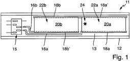
- a heater 11 is shown with a flat and elongate rectangular support 12.
- This support 12 could also be thought of as a development of a short tube of circular cross-section so that the left and right ends would be closed and the inside of the tube from the bottom the carrier 12 would be formed.
- a flat insulating layer 13 is applied on the carrier 12. This corresponds to a conventional structure.
- connection device 15 in the form of a plug or the like. appropriate. From this connection device 15 go from leads 16a and 16b, which open into connection contacts 18. The supply line 16a goes right down to a lower terminal contact 18a. Opposite is an upper terminal contact 18a ', said upper terminal contact 18a' passes directly into another upper terminal contact 18b. Actually, they form a common connection contact. Opposite the upper terminal contact 18b is below a terminal contact 18b ', which then merges into the lead 16b, and this goes to the terminal device 15th
- two heating elements 20a and 20b are provided, which are applied in an overlapping manner to the terminal contacts 18, as is known for Schichtußimplantation or Dick harshbuildbuildieri. Their lateral distance from each other is very small and is a few mm. Both heating elements 20a and 20b are of the same size and substantially the same or identical in design. As can be seen, their width is between three and four times their length, so they are very short or very wide.
- the two heating elements 20a and 20b each form a separate heating element group 22a and 22b. Thus, there are two heater groups 22a and 22b, even though each has only a single heating element 20, and they are connected in series with each other. If the heating elements 20a and 20b were connected in parallel, it would only be a single heating element group with two heating elements.
- the heating elements 20a and 20b are formed from a preferred heating element material which advantageously contains a noble metal, particularly advantageously silver and optionally also additionally palladium.
- the heater material advantageously has PTC properties.
- a heating element material is generally carbon-free or non-carbon-based, ie contains no carbon at least in the finished, ready-to-use state.
- Such heating element materials are known from the prior art and are mainly used for thick-film heating elements, as provided here. Possible application methods for the heater material are as known in the art.
- a constant or uniform thickness of the heating elements 20 is provided. This may for example be 20 microns to 70 microns, so are still in a thick film area.
- the area can be just under 40 cm 2 , so that at a voltage applied to the supply lines 16 voltage of 230 V, a power of about 2000 W is generated. This means a sheet resistance of 63 ⁇ / ⁇ and a surface load of just over 50 W / cm 2 .
- Fig. 1 is a so-called hotspot 24 drawn with an extension of about 5 mm by 5 mm. It is located in the left area of the right heating element 20a.
- the temperature increase occurring at the hotspot 24 also increases the electrical resistance in the heating element 20a in this region. Therefore, a current flow is lower here, this shifts into the relatively broader areas on the left and, of course, especially to the right.
- this area of the hotspot 24 again less heat energy is generated.
- a further increase in temperature can be slowed down or prevented and the hotspot 24 does not interfere strongly or can cause damage to the heating device 11.
- this hotspot 24 may be discovered and issued an indication to an operator that when using the heater 11 in a boiling water appliance or steam generator descaling should be made.
- the voltage may possibly also be monitored by monitoring the current flowing through the heating element 20a and the applied voltage at the connection contacts 18a 'and 18a, possibly via an additional contact at the connection contact 18a'. Changing these values can also be seen as a hotspot occurrence.
- a further heating device 111 is shown, which also has a flat and planar support 112, which is here substantially square, but otherwise its structure is similar in many respects to that of FIG Fig. 1 ,
- a connection device 115 is applied together with a connection device 115 with leads 116a and 116b.
- the lead 116a extends to terminals 118a and 118b.
- To each of these two parallel heating elements 120a and 120a 'and 120b and 120b' are provided. These are on the other end in turn connected to terminal contacts 118a 'and 118b' which converge.
- the supply line 116b extends to terminal contacts 118d 'and 118c.
- Two parallel heating elements 120d and 120d 'as well as 120c and 120c' are provided thereon. These are connected at the other end to terminal contacts 118d and 118c '. These terminals 118d and 118c 'are in turn connected to each other and to the terminals 118a' and 118b '.
- All heating elements 120 are identical and substantially square.
- the pairs of heating elements 120 connected in parallel and directly adjacent to one another could also cover the thin gap separating them and thus form a single heating element.
- two pairs of heating elements 120 form a heating element group 122a and 122b, thus a total of two heating element groups.
- a series connection of two sets of four heating elements is achieved, with the heating elements of each group of four connected in parallel. This can be recognized by the profile of the connection contacts 118.
- the heating elements 120 can those of Fig. 1 correspond.
- the carrier 112 could also be a development of a curved or even tubular support. A tubular support would then have a much greater length than width.
- connection contacts 218a and 218b are provided in the upper region, which are separate from each other or meet neither front nor on the back. Below, so to speak continuous or largely continuous a connection contact 218a '. Also, the lower terminal contact 218a 'may have a gap on the back, but it may also be continuous or circumferential.
- the terminal contact 218a is connected to a terminal contact pad 219a, which is like a kind of protrusion of the terminal 218a. Similarly, a terminal contact pad 219b departs from the terminal contact 218b.
- an electrical contact such as a line or the like. be attached.
- each heating element group 222a or 222b which are advantageously identical, is subject to the condition according to the invention.
- the individual heating elements 220a and 220b are in themselves elongated with a length which is several times the width. However, the effective length of the heating elements of a heating element group is less than their added width, so that here, too, an effective width of all heating elements together within a heating element group is greater than their effective length per heating element group.
- Fig. 4 is yet another heater 311 shown as a modification of those of Fig. 1 .
- the course of the leads 316a and 316b slightly different. This is because not only the terminal contact 318b is continuous as it already is in Fig. 1 was, but also a lower through terminal 318a is provided.
- a single heating element 320a which compared to that of the Fig. 1 again by a factor of 2 is wider than long. In particular, it is about seven times as wide as it is long.
- heating element group 322 with only a single heating element 320 is provided.
- heating element group is also used here, even if only a single heating element is contained therein.
- the heating element 320 in the middle could have a narrow gap extending over its length. It would then be two separate heating elements, but since they would be connected in parallel, their effective width would be only slightly reduced, namely only by the amount of the width of the strip left free. In addition, it would then only a single and common heating element group, since the two heating elements are indeed connected to the same connection contacts.
Landscapes
- Resistance Heating (AREA)
- Control Of Resistance Heating (AREA)
Abstract
Eine Heizeinrichtung (11) mit einem Träger (12) und mindestens einer Heizelementgruppe (22a, b) auf dem Träger weist mindestens ein Heizelement (20a, b) auf dem Träger und zwei Anschlusskontakte (18a, b) für die Heizelementgruppe auf. Die zwei Anschlusskontakte sind voneinander elektrisch getrennt und kontaktieren das einzige Heizelement oder alle Heizelemente (20a, b) der Heizelementgruppe (22a, b) elektrisch zum Anschließen an eine Stromversorgung bzw. als Leistungsanschluss. Eine effektive Breite aller Heizelemente (20a, b) innerhalb einer gemeinsamen Heizelementgruppe (22a, b) ist größer als eine effektive Länge des einzigen Heizelements oder aller Heizelemente dieser gemeinsamen Heizelementgruppe zwischen den beiden Anschlusskontakten (18a, b).A heating device (11) with a carrier (12) and at least one heating element group (22a, b) on the carrier has at least one heating element (20a, b) on the carrier and two connection contacts (18a, b) for the heating element group. The two terminal contacts are electrically isolated from each other and electrically contact the single heating element or all the heating elements (20a, b) of the heating element group (22a, b) for connection to a power supply or power connection. An effective width of all heating elements (20a, b) within a common heating element group (22a, b) is greater than an effective length of the single heating element or all heating elements of this common heating element group between the two connection contacts (18a, b).
Description
Die Erfindung betrifft eine Heizeinrichtung mit einem Träger und mindestens einer Heizelementgruppe auf dem Träger, wobei eine solche Heizelementgruppe ein Heizelement oder mehrere Heizelemente auf dem Träger aufweist.The invention relates to a heating device with a carrier and at least one heating element group on the carrier, wherein such a heating element group has a heating element or a plurality of heating elements on the carrier.
Derartige Heizeinrichtungen sind vielfältig bekannt aus dem Stand der Technik, siehe beispielsweise die
Der Erfindung liegt die Aufgabe zugrunde, eine eingangs genannte Heizeinrichtung zu schaffen, mit der Probleme des Standes der Technik gelöst werden können und es insbesondere möglich ist, eine Heizeinrichtung zweckmäßig auszugestalten für einen sicheren und zuverlässigen Betrieb, der vorzugsweise auch gegen Betriebsstörungen wie lokale Temperaturerhöhungen sicher ist.The invention has for its object to provide a heating device mentioned above, can be solved with the problems of the prior art and in particular it is possible to design a heater expedient for safe and reliable operation, preferably safe against operational disturbances such as local temperature increases is.
Gelöst wird diese Aufgabe durch eine Heizeinrichtung mit den Merkmalen des Anspruchs 1. Vorteilhafte sowie bevorzugte Ausgestaltungen der Erfindung sind Gegenstand der weiteren Ansprüche und werden im Folgenden näher erläutert. Der Wortlaut der Ansprüche wird durch ausdrückliche Bezugnahme zum Inhalt der Beschreibung gemacht.This object is achieved by a heating device with the features of claim 1. Advantageous and preferred embodiments of the invention are the subject of further claims and are explained in more detail below. The wording of the claims is incorporated herein by express reference.
Es ist vorgesehen, dass die Heizeinrichtung einen Träger und mindestens eine Heizelementgruppe auf dem Träger aufweist, also eine Heizelementgruppe oder mehrere Heizelementgruppen. Eine Heizelementgruppe wiederum weist mindestens ein Heizelement auf, das auf dem Träger aufgebracht ist, also ein Heizelement oder mehrere Heizelemente. Vorteilhaft ist es ein flächiges Schichtheizelement, insbesondere ein Dickschichtheizelement, wie es an sich aus dem Stand der Technik bekannt ist. Des Weiteren weist jede bzw. die mindestens Heizelementgruppe zwei Anschlusskontakte für die Heizelementgruppe auf, vorteilhaft genau zwei Anschlusskontakte pro Heizelementgruppe. Diese zwei Anschlusskontakte sind elektrisch voneinander getrennt und kontaktieren das einzige Heizelement oder alle Heizelemente der Heizelementgruppe elektrisch, um einen Anschluss an eine Stromversorgung bzw. Leistungsversorgung herzustellen, direkt oder indirekt. Dies bedeutet, dass in einer vorteilhaften Ausgestaltung der Erfindung pro Heizelementgruppe ein Heizelement oder mehrere Heizelemente vorgesehen sein können, deren elektrischer Anschluss bzw. deren Stromanschluss oder Leistungsanschluss mit nur genau diesen zwei Anschlusskontakten erfolgt. Ein Heizelement kann also dadurch definiert werden, dass es zwischen zwei Anschlusskontakten verläuft. An diese Anschlusskontakte können eventuell auch noch andere Heizelementgruppen oder andere Heizelemente angeschlossen sein, aber für eine Heizelementgruppe gesehen gibt es eben nur diese zwei Anschlusskontakte zum Anschließen nach extern bzw. an eine Stromversorgung bzw. Leistungsversorgung. Bevorzugt sind niemals zwei Heizelementgruppen parallel zueinander geschaltet, sondern immer nur seriell hintereinander. Parallel geschaltete Heizelemente bilden besonders bevorzugt immer eine gemeinsame Heizelementgruppe.It is provided that the heating device has a carrier and at least one heating element group on the carrier, that is to say one heating element group or several heating element groups. A heating element group in turn has at least one heating element which is applied to the carrier, that is to say one heating element or a plurality of heating elements. Advantageously, it is a sheet-like Schichtheizelement, in particular a Dickschichtheizelement, as it is known per se from the prior art. Furthermore, each or the at least heating element group has two connection contacts for the heating element group, advantageously exactly two connection contacts per heating element group. These two terminals are electrically isolated from each other and electrically contact the sole heating element or all the heating elements of the heating element group to make a connection to a power supply, directly or indirectly. This means that in an advantageous embodiment of the invention, one heating element or a plurality of heating elements can be provided per heating element group whose electrical connection or its power connection or power connection takes place with only exactly these two connection contacts. A heating element can thus be defined by running between two connection contacts. It is also possible for other heating element groups or other heating elements to be connected to these connection contacts, but as far as a heating element group is concerned, there are only these two connection contacts for connection to the external or to a power supply or power supply. Preferably, no two heater element groups are connected in parallel to each other, but always only serially in succession. Parallel heating elements particularly preferably always form a common heating element group.
Im Rahmen der vorliegenden Erfindung wird aus Gründen der einheitlichen Verwendung von Begriffen unter "Heizelementgruppe" auch eine Anordnung verstanden, die nur ein einziges Heizelement aufweist, nach allgemeinem Verständnis aber noch keine Gruppe ist.In the context of the present invention, for reasons of the uniform use of terms under "heating element group", an arrangement is also understood which has only a single heating element, but according to general understanding, is not yet a group.
Erfindungsgemäß ist vorgesehen, dass eine effektive Breite des einzigen Heizelements oder aller Heizelemente innerhalb einer gemeinsamen Heizelementgruppe mindestens so groß ist wie eine effektive Länge dieses einzigen Heizelements oder aller dieser Heizelemente dieser Heizelementgruppe im Verlauf zwischen den beiden Anschlusskontakten. In dem Fall, dass nur ein einziges Heizelement für die Heizelementgruppe vorgesehen ist, ist es erfindungsgemäß vorgesehen, dass dieses einzige Heizelement breiter ist als lang bzw. seine effektive Breite eben mindestens so groß ist oder vorteilhaft größer ist als seine Länge zwischen den beiden Anschlusskontakten. Dabei verläuft auch die Breite des Heizelements zwischen den Anschlusskontakten, wobei die Anschlusskontakte auch länger sein können als das eine einzige Heizelement oder alle Heizelemente der Heizelementgruppe breit sind. Weist eine Heizelementgruppe mehrere Heizelemente auf, so sind diese wegen ihres Anschlusses an diese beiden einzigen Anschlusskontakte parallel zueinander geschaltet. Ihre effektive Breite ist dann die aufaddierte Breite aller einzelnen Heizelemente. Dabei werden zwischen den Heizelementen einer Heizelementgruppe vorgesehene Zwischenräume nicht mitgezählt, da sie elektrisch eigentlich keine Rolle spielen wegen des Verhältnisses zwischen Länge und Breite und wegen der Parallelschaltung der Heizelemente.According to the invention, it is provided that an effective width of the single heating element or of all heating elements within a common heating element group is at least as great as an effective length of this single heating element or all of these heating elements of this heating element group in the course between the two connection contacts. In the event that only a single heating element is provided for the heating element group, it is provided according to the invention that this single heating element is wider than long or its effective width is at least as large or advantageously greater than its length between the two connection contacts. In this case, the width of the heating element extends between the terminal contacts, wherein the terminal contacts may be longer than a single heating element or all heating elements of the heating element group are wide. If a heating element group has a plurality of heating elements, these are connected in parallel to one another because of their connection to these two single connection contacts. Their effective width is then the added width of all individual heating elements. In this case, provided between the heating elements of a heating element group gaps are not counted, since they actually do not play a role electrically because of the ratio between length and width and because of the parallel connection of the heating elements.
Der Vorteil eines solchen Heizelements bzw. einer solchen Gruppe von Heizelementen besteht darin, dass sich mit der erfindungsgemäßen geometrischen Bedingung eine kleinere heiße Stelle, die beispielsweise eine Fläche zwischen 0,1% und 5% eines Heizelements bzw. aller Heizelemente einer Heizelementgruppe aufweisen kann, nicht so stark bzw. schädlich auswirkt. An einer solchen heißen Stelle bzw. an einem solchen Hotspot tritt im Stand der Technik eine Temperaturerhöhung auf, wodurch bei einem PTC-Verhalten eines Heizelements und der Temperaturerhöhung an sich beispielsweise Kalkablagerungen beim Heizen von Wasser noch verstärkt werden, wodurch die Temperatur in Folge wiederum noch stärker steigt. Der Heizelementstrom muss aber an dieser heißen Stelle vorbei und so kann im Schadensfall ein Beschädigen oder sogar Durchbrennen der Heizeinrichtung auftreten. Ist ein Heizelement bzw. eine Heizelementgruppe aber breiter als lang, um eine gewisse beheizte Fläche zu erreichen, so kann der Strom an im Verhältnis relativ kleinen heißen Stellen oder Hotspot sozusagen seitlich daneben vorbeifließen. Dadurch kühlt diese Stelle dann ab, da der Stromfluss erheblich geringer wird, und das Problem verstärkt sich zumindest nicht.The advantage of such a heating element or a group of heating elements is that, with the geometric condition according to the invention, a smaller hot spot, which for example can have an area between 0.1% and 5% of a heating element or all heating elements of a heating element group, not so strong or harmful. At such a hot spot or at such a hot spot occurs in the prior art, an increase in temperature, whereby in a PTC behavior of a heating element and the temperature increase per se, for example, limescale deposits when heating water are enhanced, which in turn the temperature in turn increases more. The Heizelementstrom must but at this hot spot over and so damage or even burning of the heater can occur in the event of damage. However, if a heating element or a heating element group is wider than it takes to reach a certain heated area, then the current can flow past at a relatively small hot spot or hot spot, as it were, laterally next to it. As a result, this point cools down, since the current flow is considerably lower, and at least the problem does not increase.
In vorteilhafter Ausgestaltung der Erfindung ist die effektive Breite des einzigen Heizelements oder aller Heizelemente zusammen innerhalb der Heizelementgruppe mindestens zweimal so groß wie die effektive Länge zwischen den beiden Anschlusskontakten. Besonders vorteilhaft kann sie dreimal bis zehnmal so groß sein. Ein Ausfall von wenigen Prozent oder sogar untern einem Prozent dieser Fläche bzw. der Heizleistung fällt dann nur unwesentlich ins Gewicht bzw. stört kaum.In an advantageous embodiment of the invention, the effective width of the single heating element or all heating elements together within the heating element group is at least twice as large as the effective length between the two connection contacts. It can be particularly advantageous three times to ten times as large. A failure of a few percent or even below one percent of this area or the heating power then falls only insignificant or hardly bothers.
In Ausgestaltung der Erfindung kann die effektive Länge des einzigen Heizelements oder aller Heizelemente einer einzigen gemeinsamen Heizelementgruppe dem Abstand zwischen den beiden Anschlusskontakten entsprechen im Bereich des Heizelements oder der Heizelemente. Während sich also die effektive Breite bei mehreren Heizelementen aufaddiert aus der gemeinsamen Breite des vom Heizelementmaterial überdeckten Bereichs, gilt dies für die Länge nicht. Sind die Heizelemente unterschiedlich lang, so wird ein gemittelter Wert als effektive Länge herangezogen. Sind alle Heizelemente einer gemeinsamen Heizelementgruppe gleich lang, was eine bevorzugte Ausgestaltung ist, so entspricht die effektive Länge der Länge eines einzigen Heizelements.In an embodiment of the invention, the effective length of the single heating element or all heating elements of a single common heating element group correspond to the distance between the two connection contacts in the region of the heating element or the heating elements. Thus, while the effective width of several heating elements adds up from the common width of the area covered by the heating element material, this does not apply to the length. If the heating elements have different lengths, then an averaged value is used as the effective length. If all the heating elements of a common heating element group have the same length, which is a preferred embodiment, then the effective length corresponds to the length of a single heating element.
Bevorzugt gilt für die beiden Anschlusskontakte einer gemeinsamen Heizelementgruppe, dass sie jeweils länger sind als ein minimaler Abstand zwischen ihnen beträgt. Dies gilt zumindest für den Bereich, in dem sie Heizelemente der gemeinsamen Heizelementgruppe kontaktieren. Darüber hinausgehend können die Anschlusskontakte noch an weitere Heizelementgruppen gehen zum elektrischen Kontakt. Schließlich können sie auch in Leiterbahnen übergehen, um an weitere Heizelementgruppen verbunden zu werden oder an die vorgenannte Stromversorgung bzw. Leistungsversorgung.Preferably applies to the two terminals of a common heating element group that they are each longer than a minimum distance between them. This applies at least to the area in which they contact heating elements of the common heating element group. In addition, the connection contacts can still go to other heating element groups for electrical contact. Finally, they can also go into tracks to to be connected to other heating element groups or to the aforementioned power supply or power supply.
In Ausgestaltung der Erfindung verlaufen die beiden Anschlusskontakte einer gemeinsamen Heizelementgruppe parallel zueinander, und zwar mindestens entsprechend einer Länge, die mindestens der effektiven Breite des einzigen Heizelements oder aller Heizelemente der gemeinsamen Heizelementgruppe entspricht. Durch einen solchen parallelen Verlauf der beiden Anschlusskontakte einer gemeinsamen Heizelementgruppe ist eine besonders einfache Ausgestaltung einer erfindungsgemäßen Heizeinrichtung möglich, da dann auch in dem Fall, dass mehrere Heizelemente innerhalb dieser Heizelementgruppe vorgesehen sind, diese alle gleich lang sind. Sie können auch gleich breit sein, was aber eigentlich nur eine untergeordnete Rolle spielt, da sie ohnehin parallel verschaltet sind. Die Schichtdicke bzw. Heizelementdicke sollte gleich sein, dazu wird noch mehr ausgeführt.In an embodiment of the invention, the two connection contacts of a common heating element group run parallel to each other, at least corresponding to a length which corresponds at least to the effective width of the single heating element or all heating elements of the common heating element group. By such a parallel course of the two terminals of a common Heizelementgruppe a particularly simple embodiment of a heating device according to the invention is possible because then even in the case that several heating elements are provided within this heating element group, they are all the same length. They can also be the same width, which actually plays only a minor role, since they are interconnected in parallel anyway. The layer thickness or heating element thickness should be the same, more will be done.
Vorteilhaft sind die beiden genannten Anschlusskontakte einer gemeinsamen Heizelementgruppe ein Leistungsanschluss für diese. Weitere elektrische Kontakte an eine Heizelementgruppe bzw. an ein Heizelement können vorhanden sein, beispielsweise zur Messung bestimmter elektrischer Größen. Diese sind dann aber lediglich als Signalanschluss ausgelegt und somit für erheblich geringere Stromflüsse ausgelegt. Des Weiteren beeinflussen sie die elektrischen Eigenschaften, insbesondere die Widerstands- und Heizeigenschaften, eines Heizelements nicht. Vorteilhaft sind diese beiden Anschlusskontakte auch die einzigen Leistungsanschlüsse einer gemeinsamen Heizelementgruppe.Advantageously, the two mentioned connection contacts of a common heating element group are a power connection for them. Further electrical contacts to a heating element group or to a heating element can be present, for example for the measurement of specific electrical quantities. These are then designed only as a signal connection and thus designed for significantly lower power flows. Furthermore, they do not affect the electrical properties, in particular the resistance and heating properties, of a heating element. Advantageously, these two connection contacts are also the only power connections of a common heating element group.
In weiterer Ausgestaltung der Erfindung erfolgt ein elektrischer Kontakt zwischen den Anschlusskontakten und dem mindestens einen Heizelement dadurch, dass das Heizelement auf die Anschlusskontakte bzw. deren Oberseite oder Oberfläche überlappt. Bei einem Herstellungsverfahren für die Heizeinrichtung wird also zuerst ein Anschlusskontakt aufgebracht und danach erst das Heizelement mit einer zumindest teilweisen Überdeckung. Dies ist aber grundsätzlich aus dem Stand der Technik bekannt und hat sich bewährt.In a further embodiment of the invention, an electrical contact between the terminal contacts and the at least one heating element takes place in that the heating element overlaps onto the connection contacts or their top or surface. In a manufacturing method for the heating device, therefore, a connection contact is first applied and then only the heating element with an at least partial overlap. However, this is basically known from the prior art and has proven itself.
Grundsätzlich ist es möglich, dass eine Heizeinrichtung nur eine einzige Heizelementgruppe aufweist. Vorteilhaft sind auf dem Träger mehrere Heizelementgruppen angeordnet, beispielsweise um eine größere Fläche oder eine bessere Flächenabdeckung zu erreichen. So können beispielsweise zwei bis fünf Heizelementgruppen auf dem Träger angeordnet sein. Diese Heizelementgruppen sind dann in sich besonders vorteilhaft gleich ausgebildet bzw. weisen jeweils gleich viele und/oder gleich große Heizelemente auf. Dadurch kann ein Layout der Heizeinrichtung leichter erstellt werden. Außerdem kann so eine möglichst gleichmäßige Wärmeerzeugung durch die Heizeinrichtung erreicht werden.In principle, it is possible that a heating device has only a single heating element group. Advantageously, a plurality of heating element groups are arranged on the carrier, for example in order to achieve a larger area or a better area coverage. For example, two to five heating element groups can be arranged on the carrier. These heating element groups are then formed in a particularly advantageous manner equal or have the same number and / or equal heating elements in each case. This can be a layout the heater are easier to create. In addition, as uniform as possible heat generation can be achieved by the heater.
In vorteilhafter Ausgestaltung der Erfindung ist eine Flächenheizleistung der Heizeinrichtung an jedem Punkt, der von Heizelementmaterial bzw. einem Heizelement bedeckt ist, überall im Wesentlichen gleich oder identisch. Somit sollte also auch eine Stromdichte überall gleich sein, zumindest im Normalbetrieb einer unbeschädigten Heizeinrichtung bzw. ohne Hotspots.In an advantageous embodiment of the invention, a surface heating power of the heater is substantially the same or identical at each point covered by heater material or heating element. Thus, a current density should be the same everywhere, at least during normal operation of an undamaged heater or without hotspots.
In vorteilhafter Ausgestaltung der Erfindung kann vorgesehen sein, dass alle Heizelementgruppen und/oder alle Heizelemente identisch zueinander bzw. gleich groß sind. Insbesondere werden vorteilhaft rechteckförmige Heizelemente vorgesehen.In an advantageous embodiment of the invention can be provided that all heating element groups and / or all heating elements are identical to each other or the same size. In particular, rectangular heating elements are advantageously provided.
Vorteilhaft weist in einer einfachen Ausgestaltung der Erfindung die mindestens eine Heizelementgruppe, besonders vorteilhaft alle Heizelementgruppen einer Heizeinrichtung, nur ein einziges Heizelement zwischen ihren beiden Anschlusskontakten auf. So wird eine maximale Flächenabdeckung erreicht.Advantageously, in a simple embodiment of the invention, the at least one heating element group, particularly advantageously all heating element groups of a heating device, only a single heating element between its two connection contacts. This achieves maximum area coverage.
In weiterer Ausgestaltung der Erfindung kann vorteilhaft vorgesehen sein, dass das mindestens eine Heizelement zwischen beiden Anschlusskontakten seiner zugehörigen Heizelementgruppe eine gleichbleibende Dicke aufweist. So ist eine Herstellung, insbesondere durch an sich bekannte Dickschichtverfahren oder Dünnschichtverfahren, vereinfacht. Besonders vorteilhaft weisen alle Heizelemente der Heizeinrichtung zwischen ihren jeweiligen Anschlusskontakten eine solche gleiche Dicke auf. So können alle Heizelemente einer Heizeinrichtung in einem gemeinsamen oder mehreren gemeinsamen gleichartigen Aufbringungsverfahren hergestellt werden, was die Herstellung wiederum vereinfacht. Außerdem kann so bevorzugt eine vorgenannte gleiche Stromdichte bzw. Flächenheizleistung erreicht werden.In a further embodiment of the invention can be advantageously provided that the at least one heating element between the two terminals of its associated heating element group has a constant thickness. Thus, a production, in particular by known per se thick-film process or thin-film process, simplified. Particularly advantageously, all heating elements of the heating device between their respective connection contacts on such a same thickness. Thus, all heating elements of a heater can be manufactured in a common or several common similar application method, which in turn simplifies the production. In addition, it is thus possible with preference to achieve the aforementioned same current density or surface heating power.
Ein Heizelement kann vorteilhaft als Dünnschichtheizelement oder als Dickschichtheizelement ausgebildet sein. Eine Grenze zwischen diesen beiden Arten liegt bei etwa 10 µm bis 20 µm Schichtdicke. Der Vorteil einer Ausgestaltung als Dickschichtheizelement liegt darin, dass diese Technik für flächige Heizeinrichtungen bewährt und beherrschbar ist.A heating element can advantageously be designed as a thin-film heating element or as a thick-film heating element. A boundary between these two types is about 10 μm to 20 μm thick. The advantage of a design as thick-film heating element is that this technique is proven and manageable for flat heating devices.
In Ausgestaltung der Erfindung kann das mindestens eine Heizelement, insbesondere alle Heizelemente einer gemeinsamen Heizelementgruppe oder sogar der gesamten Heizeinrichtung, einen positiven Temperaturkoeffizienten des elektrischen Widerstands aufweisen. Besonders vorteilhaft wird stets dasselbe Heizelementmaterial verwendet. Durch einen solchen positiven Temperaturkoeffizienten kann erreicht werden, dass im Falle eines kleinen bzw. lokal sehr begrenzten Hotspots oder eines heißen Bereichs der elektrische Widerstand dort ansteigt und ein Stromfluss um diesen Bereich herum verläuft bzw. vorbei läuft, um eine weitere Überhitzung und eine eventuelle Beschädigung der Heizeinrichtung zu vermeiden.In an embodiment of the invention, the at least one heating element, in particular all heating elements of a common heating element group or even the entire heating device, have a positive temperature coefficient of electrical resistance. Particularly advantageous always the same heating element material is used. By such a positive temperature coefficient can be achieved that in the case of a small or local very limited hotspots or a hot area where the electrical resistance rises there and a current flow passes or passes around this area to prevent further overheating and possible damage to the heater.
Das Heizelement kann aus einem beliebigen üblicherweise verwendeten Material sowie aus einem Kohlenstoff-basierten Material bestehen. In vorteilhafter Ausgestaltung der Erfindung besteht das mindestens eine Heizelement aus einem Heizelementmaterial, das nicht Kohlenstoff-basiert ist bzw. keinen Kohlenstoff aufweist, zumindest keinen elektrisch leitfähigen Kohlenstoff. Vorteilhaft kann das Heizelementmaterial ein Edelmetall wie beispielsweise Silber enthalten. Besonders vorteilhaft kann es Silber und Palladium enthalten, beispielsweise als sogenannte Silberleitpaste.The heating element can be made of any commonly used material as well as of a carbon-based material. In an advantageous embodiment of the invention, the at least one heating element consists of a heating element material that is not carbon-based or has no carbon, at least no electrically conductive carbon. Advantageously, the heating element material may contain a noble metal such as silver. It can particularly advantageously contain silver and palladium, for example as so-called silver conductive paste.
Diese und weitere Merkmale gehen außer aus den Ansprüchen auch aus der Beschreibung und den Zeichnungen hervor, wobei die einzelnen Merkmale jeweils für sich allein oder zu mehreren in Form von Unterkombinationen bei einer Ausführungsform der Erfindung und auf anderen Gebieten verwirklicht sein und vorteilhafte sowie für sich schutzfähige Ausführungen darstellen können, für die hier Schutz beansprucht wird. Die Unterteilung der Anmeldung in Zwischen-Überschriften und einzelne Abschnitte beschränkt die unter diesen gemachten Aussagen nicht in ihrer Allgemeingültigkeit.These and other features will become apparent from the claims but also from the description and drawings, wherein the individual features each alone or more in the form of sub-combinations in an embodiment of the invention and in other fields be realized and advantageous and protectable Represent embodiments for which protection is claimed here. The subdivision of the application into intermediate headings and individual sections does not limit the general validity of the statements made thereunder.
Ausführungsbeispiele der Erfindung sind in den Zeichnungen schematisch dargestellt und werden im Folgenden näher erläutert. In den Zeichnungen zeigen:
-
Fig. 1 eine Draufsicht auf eine erfindungsgemäße Heizeinrichtung mit zwei rechteckigen Heizelementen darauf, -
Fig. 2 eine alternative Heizeinrichtung mit einem in etwa quadratischen Träger und acht Heizelementen darauf, die jeweils paarweise parallel verschaltet sind, -
Fig. 3 eine Seitenansicht auf eine rohrförmige Heizeinrichtung, bei der auf die Außenseite eines rohrförmigen Trägers mehrere streifenförmige Heizelemente von unten nach oben verlaufen in zwei Heizelementgruppen und -
Fig. 4 eine Abwandlung der Heizeinrichtung ausFig. 1 mit einem einzigen sehr breiten Heizelement.
-
Fig. 1 a top view of a heater according to the invention with two rectangular heating elements on it, -
Fig. 2 an alternative heating device with an approximately square support and eight heating elements thereon, which are each connected in pairs in parallel, -
Fig. 3 a side view of a tubular heater in which on the outside of a tubular support a plurality of strip-shaped heating elements from bottom to top in two heating element groups and -
Fig. 4 a modification of the heaterFig. 1 with a single very wide heating element.
In der
Links ist auf dem Träger 12 eine Anschlusseinrichtung 15 in Form eines Steckers odgl. angebracht. Von dieser Anschlusseinrichtung 15 gehen Zuleitungen 16a und 16b ab, welche in Anschlusskontakte 18 münden. Die Zuleitung 16a geht rechts unten an einen unteren Anschlusskontakt 18a. Gegenüber liegt ein oberer Anschlusskontakt 18a', wobei dieser obere Anschlusskontakt 18a' direkt in einen weiteren oberen Anschlusskontakt 18b übergeht. Eigentlich bilden sie einen gemeinsamen Anschlusskontakt. Dem oberen Anschlusskontakt 18b gegenüber ist unten ein Anschlusskontakt 18b', der dann in die Zuleitung 16b übergeht, und diese geht an die Anschlusseinrichtung 15.Links is on the
Auf der Isolierschicht 13 sind zwei Heizelemente 20a und 20b vorgesehen, die in überlappender Weise auf die Anschlusskontakte 18 aufgebracht sind, wie dies für Schichtheizelemente bzw. Dickschichtheizelemente bekannt ist. Ihr seitlicher Abstand voneinander ist sehr gering und beträgt wenige mm. Beide Heizelemente 20a und 20b sind von der Fläche her gleich groß und im Wesentlichen auch gleich bzw. identisch ausgebildet. Wie zu erkennen ist, ist ihre Breite zwischen dreimal und viermal so groß wie ihre Länge, sie sind also sehr kurz bzw. sehr breit. Die beiden Heizelemente 20a und 20b bilden jeweils eine eigene Heizelementgruppe 22a und 22b. Es sind also zwei Heizelementgruppen 22a und 22b vorhanden, auch wenn jede nur ein einziges Heizelement 20 aufweist, und sie sind seriell miteinander verschaltet. Wären die Heizelemente 20a und 20b parallel geschaltet wäre es nur eine einzige Heizelementgruppe mit zwei Heizelementen.On the insulating
Die Heizelemente 20a und 20b sind aus einem bevorzugten Heizelementmaterial gebildet, welches vorteilhaft ein Edelmetall enthält, besonders vorteilhaft Silber und gegebenenfalls auch zusätzlich noch Palladium. Das Heizelementmaterial weist vorteilhaft PTC-Eigenschaften auf. Besonders vorteilhaft ist ganz allgemein ein Heizelementmaterial kohlenstofffrei bzw. nicht Kohlenstoff-basiert, enthält also zumindest im fertigen betriebsbereiten Zustand keinen Kohlenstoff. Derartige Heizelementmaterialien sind aus dem Stand der Technik bekannt und werden vor allem für Dickschicht-Heizelemente verwendet, wie sie hier vorgesehen sind. Mögliche Auftragverfahren für das Heizelementmaterial sind wie im Stand der Technik bekannt.The
Bei dem in der
In der
Durch eine an sich aus dem Stand der Technik in Form der
In der
Die Zuleitung 116b verläuft an Anschlusskontakte 118d' und 118c. Daran sind jeweils zwei parallele Heizelemente 120d und 120d' sowie 120c und 120c' vorgesehen. Diese sind am anderen Ende mit Anschlusskontakten 118d und 118c' verbunden. Diese Anschlusskontakte 118d und 118c' wiederum sind miteinander und mit den Anschlusskontakten 118a' und 118b' verbunden.The
Sämtliche Heizelemente 120 sind identisch ausgebildet und im Wesentlichen quadratisch. Die jeweils parallel geschalteten und direkt nebeneinanderliegenden Paare von Heizelementen 120 könnten auch die sie trennende dünne Lücke überdecken und somit ein einziges Heizelement bilden. Es bilden jeweils zwei Paare von Heizelementen 120 eine Heizelementgruppe 122a und 122b, insgesamt also zwei Heizelementgruppen. Erreicht wird mit dieser Konfiguration eine Reihenschaltung von zwei Vierergruppen von Heizelementen, wobei die Heizelemente jeder Vierergruppe in sich parallel geschaltet sind. Dies ist durch den Verlauf der Anschlusskontakte 118 zu erkennen. Auch vom Material und vom Auftragverfahren her können die Heizelemente 120 denjenigen der
In der
Der Anschlusskontakt 218a ist mit einem Anschlusskontaktfeld 219a verbunden, das wie eine Art Ausbuchtung des Anschlusskontakts 218a ist. Ähnlich geht von dem Anschlusskontakt 218b ein Anschlusskontaktfeld 219b ab. An die Anschlusskontaktfelder 219a und 219b kann, vorteilhaft durch Auflöten oder Aufschweißen, eine elektrische Kontaktierung wie beispielsweise eine Leitung odgl. angebracht werden.The
Zwischen den Anschlusskontakten 218a bzw. 218b auf der oberen Seite und dem unteren Anschlusskontakt 218a' verlaufen mehrere gleich breite, streifenförmige Heizelemente 220a und 220b. Dies bedeutet, dass hier also etwa zehn Heizelemente 220a bzw. 220b jeweils eine Heizelementgruppe bilden, und diese beiden Heizelementgruppen 222a und 222b sind dann seriell geschaltet. Auf jede Heizelementgruppe 222a bzw. 222b, die vorteilhaft identisch ausgebildet sind, trifft die erfindungsgemäße Bedingung zu. Die einzelnen Heizelemente 220a und 220b sind für sich genommen zwar länglich mit einer Länge, die das Mehrfache der Breite beträgt. Die effektive Länge der Heizelemente einer Heizelementgruppe ist jedoch geringer als ihre aufaddierte Breite, so dass auch hier pro Heizelementgruppe eine effektive Breite aller Heizelemente gemeinsam innerhalb einer Heizelementgruppe größer ist als deren effektive Länge.Between the
Da in der
In der
Bei der Heizeinrichtung 311 liegt also ein Fall vor, bei dem nur eine einzige Heizelementgruppe 322 mit nur einem einzigen Heizelement 320 vorgesehen ist. Wie eingangs erläutert worden ist, wird auch hier der Begriff der Heizelementgruppe verwendet, auch wenn darin nur ein einziges Heizelement enthalten ist.In the case of the
Durch Vergleich mit der Heizeinrichtung 11 aus
Claims (15)
wobei eine Heizelementgruppe aufweist:
eine effektive Breite des einzigen Heizelements oder aller Heizelemente (20, 120, 220, 320) gemeinsam innerhalb einer gemeinsamen Heizelementgruppe (22, 122, 222, 322) mindestens so groß ist wie eine effektive Länge des einzigen Heizelements oder aller Heizelemente dieser gemeinsamen Heizelementgruppe zwischen den beiden Anschlusskontakten (18, 118, 218, 318).
wherein a heating element group comprises:
an effective width of the single heating element or all heating elements (20, 120, 220, 320) together within a common heating element group (22, 122, 222, 322) is at least as large as an effective length of the single heating element or all heating elements of that common heating element group between the two connection contacts (18, 118, 218, 318).
Applications Claiming Priority (2)
| Application Number | Priority Date | Filing Date | Title |
|---|---|---|---|
| DE102015226053 | 2015-12-18 | ||
| DE102016209012.7A DE102016209012A1 (en) | 2015-12-18 | 2016-05-24 | heater |
Publications (1)
| Publication Number | Publication Date |
|---|---|
| EP3250003A1 true EP3250003A1 (en) | 2017-11-29 |
Family
ID=57629254
Family Applications (2)
| Application Number | Title | Priority Date | Filing Date |
|---|---|---|---|
| EP16203541.4A Active EP3182794B1 (en) | 2015-12-18 | 2016-12-12 | Heating device with a carrier and method of making it |
| EP17167149.8A Pending EP3250003A1 (en) | 2015-12-18 | 2017-04-19 | Heating device |
Family Applications Before (1)
| Application Number | Title | Priority Date | Filing Date |
|---|---|---|---|
| EP16203541.4A Active EP3182794B1 (en) | 2015-12-18 | 2016-12-12 | Heating device with a carrier and method of making it |
Country Status (7)
| Country | Link |
|---|---|
| US (1) | US20170181226A1 (en) |
| EP (2) | EP3182794B1 (en) |
| JP (2) | JP6800731B2 (en) |
| KR (1) | KR20170132695A (en) |
| CN (3) | CN107205288B (en) |
| DE (1) | DE102016209012A1 (en) |
| PL (1) | PL3182794T3 (en) |
Cited By (1)
| Publication number | Priority date | Publication date | Assignee | Title |
|---|---|---|---|---|
| DE102020207784A1 (en) | 2020-06-23 | 2021-12-23 | E.G.O. Elektro-Gerätebau GmbH | Heating device with a temperature measuring device and method for temperature measurement on the heating device and for production |
Families Citing this family (8)
| Publication number | Priority date | Publication date | Assignee | Title |
|---|---|---|---|---|
| DE102016211081A1 (en) | 2016-06-21 | 2017-12-21 | E.G.O. Elektro-Gerätebau GmbH | Method for producing a heating device and heating device |
| DE102016224069A1 (en) | 2016-12-02 | 2018-06-07 | E.G.O. Elektro-Gerätebau GmbH | Cooking utensil with a cooking plate and a heater underneath |
| US11382181B2 (en) * | 2016-12-02 | 2022-07-05 | Goodrich Corporation | Method to create carbon nanotube heaters with varying resistance |
| JP7089915B2 (en) * | 2018-03-27 | 2022-06-23 | 株式会社Lixil | Heat generator |
| EP3557144A1 (en) * | 2018-04-20 | 2019-10-23 | Future Carbon GmbH | Multi-layered composite system with a heatable layer and kit which is used to produce the multi-layered composite system |
| US11274853B2 (en) * | 2018-10-15 | 2022-03-15 | Goodrich Corporation | Additively manufactured heaters for water system components |
| CN111050435A (en) * | 2020-01-13 | 2020-04-21 | 华智算(广州)科技有限公司 | Resistance controllable heating plate along length direction and preparation process thereof |
| US11745879B2 (en) | 2020-03-20 | 2023-09-05 | Rosemount Aerospace Inc. | Thin film heater configuration for air data probe |
Citations (9)
| Publication number | Priority date | Publication date | Assignee | Title |
|---|---|---|---|---|
| EP1933598A1 (en) * | 2006-12-11 | 2008-06-18 | Behr GmbH & Co. KG | Electrical heater or supplementary heater, in particular for a heating or air conditioning assembly of a vehicle |
| US20110062140A1 (en) * | 2009-09-11 | 2011-03-17 | Canon Kabushiki Kaisha | Heater and image heating apparatus including the same |
| EP2444381A1 (en) * | 2010-10-19 | 2012-04-25 | Saint-Gobain Glass France | Transparent glazing |
| DE102012202065B3 (en) | 2012-02-10 | 2013-05-29 | E.G.O. Elektro-Gerätebau GmbH | Pump and method for heating a pump |
| DE102012200398A1 (en) | 2012-01-12 | 2013-07-18 | BSH Bosch und Siemens Hausgeräte GmbH | Water-guiding household appliance has guide path, which extends such that individual sections of guide path possesses minimum distance from one another, where liquid is guided in body with component radial to body wall |
| EP2618630A2 (en) * | 2012-01-19 | 2013-07-24 | FutureCarbon GmbH | Heating device and method for operating a heating device |
| DE102013200277A1 (en) | 2013-01-10 | 2014-01-30 | E.G.O. Elektro-Gerätebau GmbH | Heating device has measuring device that is connected to planar electrode and heating conductor, for detecting temperature dependent current flow between heating conductor and covering layer and/or dielectric insulation layer |
| DE102012213385A1 (en) | 2012-07-30 | 2014-05-22 | E.G.O. Elektro-Gerätebau GmbH | Heating and electrical appliance with heating device |
| US20160031420A1 (en) * | 2014-07-29 | 2016-02-04 | Hyundai Motor Company | Washer liquid heating apparatus integrated into washer reservoir |
Family Cites Families (26)
| Publication number | Priority date | Publication date | Assignee | Title |
|---|---|---|---|---|
| JPS5986689U (en) * | 1982-12-02 | 1984-06-12 | 東日電気株式会社 | Steam generator heater |
| DE19810848A1 (en) * | 1998-02-06 | 1999-08-12 | Heinz Zorn | Mirror heater |
| JP2002184558A (en) * | 2000-12-12 | 2002-06-28 | Ibiden Co Ltd | Heater |
| JP2003123945A (en) * | 2001-08-08 | 2003-04-25 | Fuji Name Plate Kk | Heater |
| JP2003123944A (en) * | 2001-10-05 | 2003-04-25 | Toshiba Ceramics Co Ltd | Resistance heating foil element, method of manufacturing the same and flat heater |
| EP1463380A1 (en) * | 2001-11-30 | 2004-09-29 | Ibiden Co., Ltd. | Ceramic heater |
| US7132628B2 (en) * | 2004-03-10 | 2006-11-07 | Watlow Electric Manufacturing Company | Variable watt density layered heater |
| DE102004058077A1 (en) * | 2004-12-01 | 2006-06-08 | Heraeus Noblelight Gmbh | CFC heaters |
| JP4756695B2 (en) * | 2006-02-20 | 2011-08-24 | コバレントマテリアル株式会社 | Sheet heater |
| US7741584B2 (en) * | 2007-01-21 | 2010-06-22 | Momentive Performance Materials Inc. | Encapsulated graphite heater and process |
| CN100466866C (en) * | 2007-02-05 | 2009-03-04 | 常熟市新力电子器件厂 | Electric heating tube with automatic temperature control and preventing dry burning |
| US8193475B2 (en) * | 2007-02-13 | 2012-06-05 | Advanced Materials Enterprises Company Limited | Heating apparatus and method for making the same |
| JP2009059539A (en) * | 2007-08-30 | 2009-03-19 | Harison Toshiba Lighting Corp | Planar heater, heating device, and image-forming device |
| US20100126985A1 (en) * | 2008-06-13 | 2010-05-27 | Tsinghua University | Carbon nanotube heater |
| AT508327A1 (en) * | 2008-07-29 | 2010-12-15 | Villinger Markus | HEATING DEVICE FOR DEPARTING AIRCRAFT PARTS |
| CN105810630A (en) * | 2008-08-29 | 2016-07-27 | 威科仪器有限公司 | Wafer carrier with varying thermal resistance |
| JP5430997B2 (en) * | 2009-03-30 | 2014-03-05 | 太平洋セメント株式会社 | Ceramic heater |
| KR101222639B1 (en) * | 2010-02-12 | 2013-01-16 | 성균관대학교산학협력단 | Flexible and transparent heating device using graphene and preparing method of the same |
| EP2436946B1 (en) * | 2010-09-29 | 2013-08-21 | Carl Freudenberg KG | Heating element for oscillation-based components |
| FR2968183B1 (en) * | 2010-12-06 | 2014-02-14 | Seb Sa | HOUSEHOLD APPLIANCE FOR HOT-WATER BEVERAGE PREPARATION WITH DOUBLE TANK |
| KR20110094174A (en) * | 2011-08-04 | 2011-08-22 | 한병완 | Method for manufacturing ptc film heater by roll to roll with thin metallic etched electrodes |
| US9210737B2 (en) * | 2012-02-16 | 2015-12-08 | Abominable Labs, Llc | Multiregion heated eye shield |
| JP5896142B2 (en) * | 2012-03-23 | 2016-03-30 | 東芝ライテック株式会社 | Ceramic heater and fixing device |
| WO2015048564A1 (en) * | 2013-09-29 | 2015-04-02 | Abominable Labs, Llc | Multiregion heated eye shield |
| JP2015210989A (en) * | 2014-04-28 | 2015-11-24 | 東芝ライテック株式会社 | Heater and image forming apparatus |
| CN204906731U (en) * | 2015-04-10 | 2015-12-23 | 张飞林 | Pottery electric heating assemblies |
-
2016
- 2016-05-24 DE DE102016209012.7A patent/DE102016209012A1/en active Pending
- 2016-12-12 PL PL16203541T patent/PL3182794T3/en unknown
- 2016-12-12 EP EP16203541.4A patent/EP3182794B1/en active Active
- 2016-12-16 CN CN201611273137.XA patent/CN107205288B/en active Active
- 2016-12-16 US US15/381,763 patent/US20170181226A1/en not_active Abandoned
- 2016-12-19 JP JP2016244979A patent/JP6800731B2/en active Active
-
2017
- 2017-04-19 EP EP17167149.8A patent/EP3250003A1/en active Pending
- 2017-05-10 JP JP2017093689A patent/JP2017212206A/en active Pending
- 2017-05-24 CN CN202210149836.2A patent/CN114679802A/en active Pending
- 2017-05-24 KR KR1020170064374A patent/KR20170132695A/en unknown
- 2017-05-24 CN CN201710373078.1A patent/CN107426835A/en active Pending
Patent Citations (9)
| Publication number | Priority date | Publication date | Assignee | Title |
|---|---|---|---|---|
| EP1933598A1 (en) * | 2006-12-11 | 2008-06-18 | Behr GmbH & Co. KG | Electrical heater or supplementary heater, in particular for a heating or air conditioning assembly of a vehicle |
| US20110062140A1 (en) * | 2009-09-11 | 2011-03-17 | Canon Kabushiki Kaisha | Heater and image heating apparatus including the same |
| EP2444381A1 (en) * | 2010-10-19 | 2012-04-25 | Saint-Gobain Glass France | Transparent glazing |
| DE102012200398A1 (en) | 2012-01-12 | 2013-07-18 | BSH Bosch und Siemens Hausgeräte GmbH | Water-guiding household appliance has guide path, which extends such that individual sections of guide path possesses minimum distance from one another, where liquid is guided in body with component radial to body wall |
| EP2618630A2 (en) * | 2012-01-19 | 2013-07-24 | FutureCarbon GmbH | Heating device and method for operating a heating device |
| DE102012202065B3 (en) | 2012-02-10 | 2013-05-29 | E.G.O. Elektro-Gerätebau GmbH | Pump and method for heating a pump |
| DE102012213385A1 (en) | 2012-07-30 | 2014-05-22 | E.G.O. Elektro-Gerätebau GmbH | Heating and electrical appliance with heating device |
| DE102013200277A1 (en) | 2013-01-10 | 2014-01-30 | E.G.O. Elektro-Gerätebau GmbH | Heating device has measuring device that is connected to planar electrode and heating conductor, for detecting temperature dependent current flow between heating conductor and covering layer and/or dielectric insulation layer |
| US20160031420A1 (en) * | 2014-07-29 | 2016-02-04 | Hyundai Motor Company | Washer liquid heating apparatus integrated into washer reservoir |
Cited By (2)
| Publication number | Priority date | Publication date | Assignee | Title |
|---|---|---|---|---|
| DE102020207784A1 (en) | 2020-06-23 | 2021-12-23 | E.G.O. Elektro-Gerätebau GmbH | Heating device with a temperature measuring device and method for temperature measurement on the heating device and for production |
| EP3930421A1 (en) | 2020-06-23 | 2021-12-29 | E.G.O. Elektro-Gerätebau GmbH | Heating device with a temperature measuring device and method for temperature measurement at the heating device and for its production |
Also Published As
| Publication number | Publication date |
|---|---|
| EP3182794B1 (en) | 2020-12-09 |
| EP3182794A1 (en) | 2017-06-21 |
| CN114679802A (en) | 2022-06-28 |
| CN107205288B (en) | 2022-10-28 |
| CN107426835A (en) | 2017-12-01 |
| DE102016209012A1 (en) | 2017-06-22 |
| KR20170132695A (en) | 2017-12-04 |
| PL3182794T3 (en) | 2021-05-17 |
| JP2017112114A (en) | 2017-06-22 |
| JP2017212206A (en) | 2017-11-30 |
| US20170181226A1 (en) | 2017-06-22 |
| JP6800731B2 (en) | 2020-12-16 |
| CN107205288A (en) | 2017-09-26 |
Similar Documents
| Publication | Publication Date | Title |
|---|---|---|
| EP3250003A1 (en) | Heating device | |
| EP3145273B1 (en) | Heating device for heating water and a method for operating such a heating device | |
| WO2013117603A1 (en) | Pump with integrated heating element | |
| EP3197241B1 (en) | Heating device and method for measuring the temperature on the heating element | |
| DE102018215879A1 (en) | Plug connection with redundancy and vehicle with such | |
| EP2859561A1 (en) | Contact element for a varistor | |
| EP3614797A1 (en) | Heating device and method for operating a heating device | |
| DE102018217239A1 (en) | Heater and method for temperature detection on a heater | |
| DE102008030262A1 (en) | Solar cell and process for producing a solar cell | |
| DE102015218121A1 (en) | Heating device for heating water and method for operating such a heater | |
| DD259026A5 (en) | ELECTRIC HEATING DEVICE FOR FLUIDS | |
| EP1467597A2 (en) | Heating apparatus | |
| DE102018208252A1 (en) | Method for producing a heating device and heating device produced therewith | |
| DE112019004929T5 (en) | Protective element | |
| EP3261409A1 (en) | Method of manufacturing a heating device and heating device | |
| DE2403117C2 (en) | High voltage circuit breaker | |
| DE554319C (en) | Extinguishing spark arrester with circuit breaker | |
| DE10058908C1 (en) | Arrangement for reducing overvoltages with several varistors | |
| EP3930421A1 (en) | Heating device with a temperature measuring device and method for temperature measurement at the heating device and for its production | |
| DE2222203A1 (en) | Device for quickly heating food in a container | |
| DE1588238C3 (en) | Surge protection device | |
| DE102015218120B4 (en) | Method for operating a heating device for heating water, heating device and dishwasher | |
| DE748900C (en) | Surge arresters | |
| AT200640B (en) | Valve arrester | |
| DE1615286C3 (en) | Control device |
Legal Events
| Date | Code | Title | Description |
|---|---|---|---|
| PUAI | Public reference made under article 153(3) epc to a published international application that has entered the european phase |
Free format text: ORIGINAL CODE: 0009012 |
|
| STAA | Information on the status of an ep patent application or granted ep patent |
Free format text: STATUS: THE APPLICATION HAS BEEN PUBLISHED |
|
| AK | Designated contracting states |
Kind code of ref document: A1 Designated state(s): AL AT BE BG CH CY CZ DE DK EE ES FI FR GB GR HR HU IE IS IT LI LT LU LV MC MK MT NL NO PL PT RO RS SE SI SK SM TR |
|
| AX | Request for extension of the european patent |
Extension state: BA ME |
|
| STAA | Information on the status of an ep patent application or granted ep patent |
Free format text: STATUS: REQUEST FOR EXAMINATION WAS MADE |
|
| 17P | Request for examination filed |
Effective date: 20180509 |
|
| RBV | Designated contracting states (corrected) |
Designated state(s): AL AT BE BG CH CY CZ DE DK EE ES FI FR GB GR HR HU IE IS IT LI LT LU LV MC MK MT NL NO PL PT RO RS SE SI SK SM TR |
|
| STAA | Information on the status of an ep patent application or granted ep patent |
Free format text: STATUS: EXAMINATION IS IN PROGRESS |
|
| 17Q | First examination report despatched |
Effective date: 20191111 |
|
| STAA | Information on the status of an ep patent application or granted ep patent |
Free format text: STATUS: EXAMINATION IS IN PROGRESS |
|
| STAA | Information on the status of an ep patent application or granted ep patent |
Free format text: STATUS: EXAMINATION IS IN PROGRESS |