EP3145273B1 - Heating device for heating water and a method for operating such a heating device - Google Patents
Heating device for heating water and a method for operating such a heating device Download PDFInfo
- Publication number
- EP3145273B1 EP3145273B1 EP16188807.8A EP16188807A EP3145273B1 EP 3145273 B1 EP3145273 B1 EP 3145273B1 EP 16188807 A EP16188807 A EP 16188807A EP 3145273 B1 EP3145273 B1 EP 3145273B1
- Authority
- EP
- European Patent Office
- Prior art keywords
- heating
- heating element
- carrier
- leakage current
- dielectric layer
- Prior art date
- Legal status (The legal status is an assumption and is not a legal conclusion. Google has not performed a legal analysis and makes no representation as to the accuracy of the status listed.)
- Active
Links
- 238000010438 heat treatment Methods 0.000 title claims description 267
- 238000000034 method Methods 0.000 title claims description 20
- 239000008236 heating water Substances 0.000 title claims description 8
- 239000004020 conductor Substances 0.000 claims description 58
- XLYOFNOQVPJJNP-UHFFFAOYSA-N water Substances O XLYOFNOQVPJJNP-UHFFFAOYSA-N 0.000 claims description 22
- 238000012544 monitoring process Methods 0.000 claims description 10
- 230000008859 change Effects 0.000 claims description 7
- 238000004140 cleaning Methods 0.000 claims description 3
- 230000004044 response Effects 0.000 claims description 2
- 230000015572 biosynthetic process Effects 0.000 claims 18
- 208000004434 Calcinosis Diseases 0.000 description 50
- 230000002308 calcification Effects 0.000 description 50
- 230000006378 damage Effects 0.000 description 11
- 238000013021 overheating Methods 0.000 description 8
- 238000009413 insulation Methods 0.000 description 5
- 239000000463 material Substances 0.000 description 5
- 230000011664 signaling Effects 0.000 description 5
- 238000010411 cooking Methods 0.000 description 4
- 230000007423 decrease Effects 0.000 description 4
- 238000001514 detection method Methods 0.000 description 4
- 230000008569 process Effects 0.000 description 4
- 239000011521 glass Substances 0.000 description 3
- 230000009467 reduction Effects 0.000 description 3
- 229910000831 Steel Inorganic materials 0.000 description 2
- 230000003247 decreasing effect Effects 0.000 description 2
- 238000010586 diagram Methods 0.000 description 2
- 238000009826 distribution Methods 0.000 description 2
- 239000002241 glass-ceramic Substances 0.000 description 2
- 239000002184 metal Substances 0.000 description 2
- 230000000630 rising effect Effects 0.000 description 2
- 239000007787 solid Substances 0.000 description 2
- 239000010959 steel Substances 0.000 description 2
- 238000012546 transfer Methods 0.000 description 2
- 239000002699 waste material Substances 0.000 description 2
- 235000019738 Limestone Nutrition 0.000 description 1
- 230000002159 abnormal effect Effects 0.000 description 1
- 230000006399 behavior Effects 0.000 description 1
- 230000008901 benefit Effects 0.000 description 1
- 230000033228 biological regulation Effects 0.000 description 1
- 238000009835 boiling Methods 0.000 description 1
- 238000007796 conventional method Methods 0.000 description 1
- 210000003298 dental enamel Anatomy 0.000 description 1
- 238000013461 design Methods 0.000 description 1
- 238000001035 drying Methods 0.000 description 1
- 238000010292 electrical insulation Methods 0.000 description 1
- 230000007613 environmental effect Effects 0.000 description 1
- 238000011156 evaluation Methods 0.000 description 1
- 239000006028 limestone Substances 0.000 description 1
- 238000012423 maintenance Methods 0.000 description 1
- 238000004519 manufacturing process Methods 0.000 description 1
- 229910001220 stainless steel Inorganic materials 0.000 description 1
- 239000010935 stainless steel Substances 0.000 description 1
- 230000002459 sustained effect Effects 0.000 description 1
- 230000002123 temporal effect Effects 0.000 description 1
- 230000000007 visual effect Effects 0.000 description 1
Images


Classifications
-
- H—ELECTRICITY
- H05—ELECTRIC TECHNIQUES NOT OTHERWISE PROVIDED FOR
- H05B—ELECTRIC HEATING; ELECTRIC LIGHT SOURCES NOT OTHERWISE PROVIDED FOR; CIRCUIT ARRANGEMENTS FOR ELECTRIC LIGHT SOURCES, IN GENERAL
- H05B1/00—Details of electric heating devices
- H05B1/02—Automatic switching arrangements specially adapted to apparatus ; Control of heating devices
- H05B1/0227—Applications
- H05B1/023—Industrial applications
- H05B1/0244—Heating of fluids
-
- A—HUMAN NECESSITIES
- A47—FURNITURE; DOMESTIC ARTICLES OR APPLIANCES; COFFEE MILLS; SPICE MILLS; SUCTION CLEANERS IN GENERAL
- A47L—DOMESTIC WASHING OR CLEANING; SUCTION CLEANERS IN GENERAL
- A47L15/00—Washing or rinsing machines for crockery or tableware
- A47L15/42—Details
- A47L15/4285—Water-heater arrangements
-
- F—MECHANICAL ENGINEERING; LIGHTING; HEATING; WEAPONS; BLASTING
- F24—HEATING; RANGES; VENTILATING
- F24H—FLUID HEATERS, e.g. WATER OR AIR HEATERS, HAVING HEAT-GENERATING MEANS, e.g. HEAT PUMPS, IN GENERAL
- F24H1/00—Water heaters, e.g. boilers, continuous-flow heaters or water-storage heaters
- F24H1/0018—Water heaters, e.g. boilers, continuous-flow heaters or water-storage heaters using electric energy supply
-
- F—MECHANICAL ENGINEERING; LIGHTING; HEATING; WEAPONS; BLASTING
- F24—HEATING; RANGES; VENTILATING
- F24H—FLUID HEATERS, e.g. WATER OR AIR HEATERS, HAVING HEAT-GENERATING MEANS, e.g. HEAT PUMPS, IN GENERAL
- F24H1/00—Water heaters, e.g. boilers, continuous-flow heaters or water-storage heaters
- F24H1/10—Continuous-flow heaters, i.e. heaters in which heat is generated only while the water is flowing, e.g. with direct contact of the water with the heating medium
- F24H1/101—Continuous-flow heaters, i.e. heaters in which heat is generated only while the water is flowing, e.g. with direct contact of the water with the heating medium using electric energy supply
- F24H1/102—Continuous-flow heaters, i.e. heaters in which heat is generated only while the water is flowing, e.g. with direct contact of the water with the heating medium using electric energy supply with resistance
-
- H—ELECTRICITY
- H05—ELECTRIC TECHNIQUES NOT OTHERWISE PROVIDED FOR
- H05B—ELECTRIC HEATING; ELECTRIC LIGHT SOURCES NOT OTHERWISE PROVIDED FOR; CIRCUIT ARRANGEMENTS FOR ELECTRIC LIGHT SOURCES, IN GENERAL
- H05B1/00—Details of electric heating devices
- H05B1/02—Automatic switching arrangements specially adapted to apparatus ; Control of heating devices
- H05B1/0227—Applications
- H05B1/0288—Applications for non specified applications
- H05B1/0294—Planar elements
-
- H—ELECTRICITY
- H05—ELECTRIC TECHNIQUES NOT OTHERWISE PROVIDED FOR
- H05B—ELECTRIC HEATING; ELECTRIC LIGHT SOURCES NOT OTHERWISE PROVIDED FOR; CIRCUIT ARRANGEMENTS FOR ELECTRIC LIGHT SOURCES, IN GENERAL
- H05B3/00—Ohmic-resistance heating
- H05B3/20—Heating elements having extended surface area substantially in a two-dimensional plane, e.g. plate-heater
- H05B3/22—Heating elements having extended surface area substantially in a two-dimensional plane, e.g. plate-heater non-flexible
- H05B3/26—Heating elements having extended surface area substantially in a two-dimensional plane, e.g. plate-heater non-flexible heating conductor mounted on insulating base
-
- A—HUMAN NECESSITIES
- A47—FURNITURE; DOMESTIC ARTICLES OR APPLIANCES; COFFEE MILLS; SPICE MILLS; SUCTION CLEANERS IN GENERAL
- A47L—DOMESTIC WASHING OR CLEANING; SUCTION CLEANERS IN GENERAL
- A47L2401/00—Automatic detection in controlling methods of washing or rinsing machines for crockery or tableware, e.g. information provided by sensors entered into controlling devices
- A47L2401/30—Variation of electrical, magnetical or optical quantities
-
- A—HUMAN NECESSITIES
- A47—FURNITURE; DOMESTIC ARTICLES OR APPLIANCES; COFFEE MILLS; SPICE MILLS; SUCTION CLEANERS IN GENERAL
- A47L—DOMESTIC WASHING OR CLEANING; SUCTION CLEANERS IN GENERAL
- A47L2501/00—Output in controlling method of washing or rinsing machines for crockery or tableware, i.e. quantities or components controlled, or actions performed by the controlling device executing the controlling method
- A47L2501/06—Water heaters
-
- F—MECHANICAL ENGINEERING; LIGHTING; HEATING; WEAPONS; BLASTING
- F24—HEATING; RANGES; VENTILATING
- F24H—FLUID HEATERS, e.g. WATER OR AIR HEATERS, HAVING HEAT-GENERATING MEANS, e.g. HEAT PUMPS, IN GENERAL
- F24H2250/00—Electrical heat generating means
- F24H2250/04—Positive or negative temperature coefficients, e.g. PTC, NTC
-
- H—ELECTRICITY
- H05—ELECTRIC TECHNIQUES NOT OTHERWISE PROVIDED FOR
- H05B—ELECTRIC HEATING; ELECTRIC LIGHT SOURCES NOT OTHERWISE PROVIDED FOR; CIRCUIT ARRANGEMENTS FOR ELECTRIC LIGHT SOURCES, IN GENERAL
- H05B2203/00—Aspects relating to Ohmic resistive heating covered by group H05B3/00
- H05B2203/002—Heaters using a particular layout for the resistive material or resistive elements
- H05B2203/005—Heaters using a particular layout for the resistive material or resistive elements using multiple resistive elements or resistive zones isolated from each other
-
- H—ELECTRICITY
- H05—ELECTRIC TECHNIQUES NOT OTHERWISE PROVIDED FOR
- H05B—ELECTRIC HEATING; ELECTRIC LIGHT SOURCES NOT OTHERWISE PROVIDED FOR; CIRCUIT ARRANGEMENTS FOR ELECTRIC LIGHT SOURCES, IN GENERAL
- H05B2203/00—Aspects relating to Ohmic resistive heating covered by group H05B3/00
- H05B2203/013—Heaters using resistive films or coatings
-
- H—ELECTRICITY
- H05—ELECTRIC TECHNIQUES NOT OTHERWISE PROVIDED FOR
- H05B—ELECTRIC HEATING; ELECTRIC LIGHT SOURCES NOT OTHERWISE PROVIDED FOR; CIRCUIT ARRANGEMENTS FOR ELECTRIC LIGHT SOURCES, IN GENERAL
- H05B2203/00—Aspects relating to Ohmic resistive heating covered by group H05B3/00
- H05B2203/019—Heaters using heating elements having a negative temperature coefficient
-
- H—ELECTRICITY
- H05—ELECTRIC TECHNIQUES NOT OTHERWISE PROVIDED FOR
- H05B—ELECTRIC HEATING; ELECTRIC LIGHT SOURCES NOT OTHERWISE PROVIDED FOR; CIRCUIT ARRANGEMENTS FOR ELECTRIC LIGHT SOURCES, IN GENERAL
- H05B2203/00—Aspects relating to Ohmic resistive heating covered by group H05B3/00
- H05B2203/02—Heaters using heating elements having a positive temperature coefficient
-
- H—ELECTRICITY
- H05—ELECTRIC TECHNIQUES NOT OTHERWISE PROVIDED FOR
- H05B—ELECTRIC HEATING; ELECTRIC LIGHT SOURCES NOT OTHERWISE PROVIDED FOR; CIRCUIT ARRANGEMENTS FOR ELECTRIC LIGHT SOURCES, IN GENERAL
- H05B2203/00—Aspects relating to Ohmic resistive heating covered by group H05B3/00
- H05B2203/021—Heaters specially adapted for heating liquids
-
- H—ELECTRICITY
- H05—ELECTRIC TECHNIQUES NOT OTHERWISE PROVIDED FOR
- H05B—ELECTRIC HEATING; ELECTRIC LIGHT SOURCES NOT OTHERWISE PROVIDED FOR; CIRCUIT ARRANGEMENTS FOR ELECTRIC LIGHT SOURCES, IN GENERAL
- H05B2203/00—Aspects relating to Ohmic resistive heating covered by group H05B3/00
- H05B2203/03—Heaters specially adapted for heating hand held tools
-
- H—ELECTRICITY
- H05—ELECTRIC TECHNIQUES NOT OTHERWISE PROVIDED FOR
- H05B—ELECTRIC HEATING; ELECTRIC LIGHT SOURCES NOT OTHERWISE PROVIDED FOR; CIRCUIT ARRANGEMENTS FOR ELECTRIC LIGHT SOURCES, IN GENERAL
- H05B2203/00—Aspects relating to Ohmic resistive heating covered by group H05B3/00
- H05B2203/037—Heaters with zones of different power density
Definitions
- the invention relates to a heater for heating water and a method for operating such a heater for heating water.
- a heating device in which, so to speak, by means of a dielectric layer between two electrically conductive pads a large-scale monitoring of the heater or a heating element and detection of localized or small-scale overheating or calcification is possible.
- a heating device in which a first dielectric layer made of enamel is applied to a hotplate made of steel. On top of that is applied a conductive thick film which is covered by a second dielectric layer. Heating conductors are first applied to this second dielectric layer. The heating conductors are exposed on their side facing away from the second dielectric layer side.
- a heater having a similar structure as described above is known.
- a carrier which may be made of steel
- an electrically insulating layer is applied, are applied to the two web-shaped elongated electrodes.
- a dielectric layer is applied, which is electrically insulating and advantageously has good thermal conductivity.
- heating conductors are applied, which are also exposed down.
- the invention has for its object to provide an aforementioned heating device and a method for their operation, with which problems of the prior art can be solved and it is in particular possible to recognize calcifications on a medium side of the carrier and thus a potential source of danger or to prevent damage to the heater.
- the heating device for heating water which is intended to flow through a carrier in particular or should flow past it, especially on a so-called medium side of the carrier, such a carrier.
- On this support at least one heating element is applied, which has a single heat conductor or has a plurality of heating conductors connected in series.
- This is advantageously a Dick SchweizerHeizelement with two electrical connections, between which extend the single or its individual successively connected or adjoining heating element.
- the heating conductors may each be straight sections of the heating element, which may in particular have a meandering course in particular. It can also be provided a plurality of such trained heating elements, advantageously at least two.
- the heating device has at least one planar dielectric layer, which essentially covers the heating conductors or the heating element.
- the dielectric layer does not necessarily have to rest directly on the or a heating element. It actually has electrically insulating properties, but at temperatures from 200 ° C or only from 300 ° C but decreases their electrical resistance.
- Such dielectric layers consist for example of glass or glass ceramic and are in the aforementioned DE 102013200277 A1 described in more detail.
- a dielectric layer is provided on both sides each with an electrically conductive pad.
- these pads are applied directly to the dielectric layer and can in particular detect a current flowing through the dielectric layer or so-called leakage current.
- the electrically conductive connection surfaces can have the same overlap, at least as far as an outer contour or maximum clamping of the surface is concerned, depending on how many dielectric layers are provided next to one another on or above the heating elements.
- One of the electrically conductive connection surfaces can advantageously also be formed over the entire surface or closed.
- At least one of the pads is connected to a controller or measuring device of a controller for evaluating a leakage current as a current flow through the dielectric layer. So just the leakage current can be monitored in terms of its time course or a possible rapid increase.
- the heating element with measuring means for monitoring a Schuleiterstroms by this heating element and thus connected by all its heating conductors.
- just the Schuleiterstrom can be monitored or evaluated, in particular with regard to a decrease due to increasing resistance of the heating element with increasing or too high temperature, if the heating element has a positive temperature coefficient of its resistance in one embodiment of the invention.
- the heating element in another embodiment of the invention has a negative temperature coefficient of its resistance, an increase in the Schuleiterstroms be recognized due to decreasing resistance of the heating element with increasing or too high temperature. Since the control or measuring device monitors the heating conductor current and, in addition, the voltage can be measured, the heat transfer can also be evaluated in the form of a thermal resistance.
- Such overheating is usually caused by calcifications, as will be explained in more detail below, or by emptying a water-filled heater or dry running when used in a pump.
- hot spots which are caused by a punctiform or small-scale, not complete detachment of a calcification, which is additionally hindered by a gap between the medium side of the carrier and the limestone layer, the heat transfer.
- dangerous overheating may occur, although small or locally very limited, but also could cause damage or destruction of the heater.
- the carrier is advantageously made of metal.
- an insulating layer is applied for a layer structure, on which in turn the heating element or the heating elements are applied.
- thick-film heating elements are preferred, for example with exactly one or more heat conductors in a total generated meander shape.
- planar dielectric layers applied, advantageously as a closed surface.
- a planar dielectric layer may substantially cover a rectangle.
- a dielectric layer also acts as electrical insulation, at least in the range of normal operating temperatures.
- an electrically conductive connection area can be applied to the dielectric layer with essentially the same area.
- any electrically conductive material can be used.
- the other electrically conductive pad to the dielectric layer is then formed by the heating element or the heating elements or its heating conductors. During operation of the heater these are connected to an operating voltage and flows through the Schuleiterstrom. As the insulation properties of a dielectric layer become smaller, a usually small current can then flow as leakage current through the dielectric layer to the other electrically conductive connection area. This can be detected by the aforementioned connection to a controller.
- the controller advantageously has a memory to store reference values for the heating element temperature, dielectric layer signals or a heating conductor current during normal operation. Values can also be stored for abnormal operating states, in particular for locally limited or small scale calcifications with regard to the then expected dielectric layer signals or a heating conductor current as well as values for the aforementioned hot spots and for surface or large-scale calcification. This can be, for example, a limit value for the dielectric current or leakage current, which may not be exceeded or, when it is reached, the heating device has to be switched off.
- a power density of the heating element may advantageously be at least 30 W / cm 2 or at least 100 W / cm 2 . Particularly advantageous, the power density can be a maximum of 150 W / cm 2 or even 200 W / cm 2 . So a fast responding and very powerful heater is given in a small footprint.
- the heating elements engage with one another or are arranged in an entangled manner, preferably with heat conductors as sections of the heating elements which run straight and parallel to one another.
- the heating elements can advantageously be bifilar, especially in meandering form. Between two parallel heating conductors of a heating element, at least one heating conductor of another heating element can run, in particular parallel thereto.
- each heating element runs close to each other, but are separated in terms of area or do not engage in each other.
- Each heating element takes so to speak, a surface with a closed outer contour, in particular a rectangular surface or a quadrangular surface into which no part of another heating element protrudes.
- the heating device has exactly two or three heating elements. Two heating elements can be interlocked or interlocked according to the first embodiment of the invention mentioned above. It may be provided an additional third heating element, which is then separated in terms of area. If exactly three heating elements are provided, they can advantageously according to the second aforementioned embodiment of the invention all three run close to each other and be separated in terms of area.
- At least two electrically separate and independently operable heating elements are mounted on the carrier and a single planar dielectric layer is provided on one side of the heating elements for connection to the control or measuring device for detecting a leakage current, wherein the dielectric layer substantially covers all the heating elements ,
- the one pad is then formed in each case by the heating elements.
- the other pad for example as an electrode, can either cover the entire surface of the dielectric layer or be divided into a plurality of pads or partial electrodes, the distribution of which in turn corresponds to the heating elements or covers them substantially exactly with their course. This has the advantage that even complicated courses for the heating elements, in particular intermeshing courses, can also be simulated with the connection surfaces.
- both the Schuleiterstrom by the heating element or by the heating element and a leakage through the dielectric layer are monitored during operation of the heater for heating water, including its temporal progressions are monitored and may also be stored as Radiotokollmaschine. There are three cases to be distinguished.
- a PTC heat conductor can be detected at a slow or so to slow drop of the Schuleiterstroms a large scale calcification on a medium side of the carrier or can such a slow drop of Schuleiterstroms as a such large scale calcification can be defined.
- a large scale calcification grows slowly over the operating time, the conductor temperature rises slowly with the operating time due to the decreasing heat capacity and the Schuleiterstrom falls off. It can various measures follow, such as an indication to a user that a descaling or cleaning of the heater is necessary, or a temporary temporary power reduction with simultaneous display.
- Such a slow drop in the heating conductor current is when it falls by at least 2% in less than 100 hours.
- a temperature sensor may be provided on the heating device, advantageously at a distance from the heating element or its heating conductors. This can be a small sensor, such as an NTC. The distance should be so large that the temperature sensor detects only the temperature at the carrier and thus the water.
- a large-scale calcification can be detected on a medium side of the carrier at a slow or so to slow rise of the Schuleiterstroms or can such a slow increase of the Schuleiterstroms as a such large scale calcification can be defined.
- the same values as previously explained for the first case may apply, namely that such a slow increase in the heating conductor current is present when it increases by at least 2% in less than 100 hours. It may also increase by at least 3% to 5% in less than 100 hours.
- too rapid a rise in the leakage current can be detected as a locally limited or small-scale calcification or an aforementioned hot spot on the medium side of the carrier. This should be noticeable to the controller, but does not necessarily have to lead to a reduction of the heating power or shutdown of the heater.
- Such a too rapid increase in leakage current occurs when the leakage current increases by at least 30% in less than 20 hours, possibly by at least 30% in less than 5 hours or by at least 50% in less than 10 hours.
- an absolute maximum value or limit value for the leakage current is exceeded, not only so that such a localized or small scale calcification or hot spot on the medium side of the carrier is detected, but thus at least reduced or the heating power even the heater is turned off.
- the limit value may be at least 200% of the leakage current which is present at the beginning of the operation of the heating device in the clean state or without calcification of the medium side of the carrier. It is also possible to provide an absolute limit value for the leakage current. Thus it can be provided that the leakage current may amount to a maximum of 20 mA or 30 mA, otherwise a shutdown occurs because of a hot spot.
- heating elements can be operated one after the other individually, wherein in each individual operating case the leakage current is detected at the at least one dielectric layer above the heating element currently being operated and under certain circumstances is also stored as operation logging.
- the leakage current in the individual operation of the heating elements is different or at least 10% different, in particular by at least 30% different, a localized or small scale calcification on the medium side of the carrier in the region of the heating element detected with the higher leakage current or it is detected an aforementioned hot spot.
- a visual and / or acoustic signaling to an operator.
- a cleaning or descaling of the heater or provided with the heater device should be made.
- the operation of the heater can still go on easily, either with full heating power or at least reduced Heating capacity.
- the heating power has to be reduced by 20% to 50%, but at least the heating device can continue to be operated.
- either the operation can then be continued only with low heating power, for example a maximum of 20% to 30%, or else the heating device is completely switched off.
- a reduction in the power of the heater can be evenly distributed to the individual heating elements if several of them are provided.
- the heating power of the affected heating element can be greatly reduced.
- this heating element or, alternatively, the entire heater can also be switched off immediately. This applies in particular if, as explained above, an absolute maximum value or limit value for the leakage current has also been exceeded. Otherwise, there is the risk of sustained damage or even destruction of the heater not only in the area of this heating element, but even the entire heater. Then it is possible that after a waiting time of 2 seconds to 20 seconds, the heater or the affected heating element is turned on again, advantageously with the same heating power as before or immediately with full heating power, so very fast.
- the performance of this heating element can be reduced or it can be switched off completely in one case after recognizing a locally limited or small scale calcification on the medium side of the carrier in the region of a heating element. At least one further heating element is then operated with unchanged performance, since it is safe in this case. In the other case that a large-scale calcification on the medium side of the carrier is detected, the heating element located there or generally a heating element with at least one further heating element can be connected in series to continue to operate the heater with a reduced overall power. These can generally be two different cases of emergency operation.
- the individual heating elements can be interconnected differently, preferably they can be operated serially or in parallel or individually.
- the heating elements have different power values. They can then be switched in parallel, by power, serial, single, or for maximum power.
- the heating conductor current drops significantly faster in a PTC heating conductor, and it increases significantly faster in an NTC heating conductor than in a large-scale calcification. There is no heat removed. Furthermore, the leakage current increases, but with almost the same speed as the Schuleiterstrom drops or increases, since it is not a local overheating, but a large area or full-surface. In this case, the entire heater should be shut down immediately, because otherwise a further operation makes no sense and above all the risk of damage is too great. In addition, a corresponding signal should be output to an operator.
- the method for operating a heating device according to the invention of a dishwasher is used, wherein advantageously the dishwasher has a controller for the operation of a water softening in the dishwasher. It can be provided that at the beginning of the operation of the dishwasher, ie after the first start-up, the water softening in the dishwasher is lowered for a lower water softening. This can be lowered or operated in the lowered state until over a corresponding slow drop or rise of Schuleiterstroms in the manner previously explained a large scale calcification on a medium side of the carrier is detected. In response, signaling to an operator may occur that the carrier or heater is to be descaled manually.
- the control of the dishwasher can automatically increase the water softening again, in particular increase briefly for a short time and then lower it again, in order to continue working with reduced water softening.
- a heating device according to the invention can for example be installed in a pump for heating and for conveying the water in the dishwasher, as for example the DE 102010043727 A1 shows.
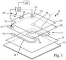
- the heater 11 is shown in an exploded view with an oblique view showing the layer structure. It corresponds to the one from the aforementioned DE 102013200277 A1 ,
- the heating device 11 has a carrier 13, which here consists of metal or stainless steel. It can be flat or flat, alternatively also tubular, as it is from the aforementioned DE 102010043727 A1 is known. On its underside or medium side is to be heated water or flows to be heated Waser over.
- a dielectric insulating layer 15 is provided as the base insulation of the carrier 13, which may consist of glass or glass ceramic. It must be electrically insulated, even at high temperatures. Such a material is known to those skilled in principle for insulation layers.
- a single heating element 17 is applied with meandering course, consisting of individual successively or serially connected heating conductors 17 '. These are largely straight and connected by curved sections. But it could also be provided a single heating element, which is also considerably wider than the narrow heating element 17 'shown here, see also the Fig. 2 ,
- the heating element 17 is formed as a thick-film heating element made of conventional material and applied by conventional methods. At its two ends are enlarged fields as Edelleiteressore 18, which may also be made of other material, such as a usual for thick film heat conductor contact material with significantly better electrical conductivity and especially better contacting properties.
- a dielectric layer 20 is applied over a large area, which may be glass-like or a glass layer.
- an electrode 24 is applied as an electrically conductive pad, in the form of a large-area layer. This is here just as large as the carrier 13 and the insulating layer 15.
- the electrode 24 should not overlap directly on the carrier 13 or the heating element 17, since it must be isolated from the carrier 13 and heating element 17.
- On the electrode 24 may be another cover or insulation layer, but need not. It has two cutouts 25 at the corners, which, together with the underlying windows 21 in the dielectric layer 20, allow a previously described contacting with the heat conductor contacts 18.
- the heating element 17 or its heating conductor 17 'form the other or first connection surface.
- the controller 29 has a memory 29 'on. This is known from the prior art and need not be explained in detail.
- a measuring device 30 is shown, which is connected on the one hand to the electrode 24 via an electrode contact 26 and on the other hand to the heating element 17. As previously explained, the dielectric and resistive properties of the second dielectric layer 20 change with temperature, and the current detected by the measuring device 30 correspondingly increases with increasing temperature. The measuring device then detects this change in the properties of the dielectric layer 20 between heating element 17 and electrode 24.
- Fig. 2 is an embodiment of a heater 111 according to the invention with layer structure to see in a very simplified side view.
- a carrier 112 which may form a container such as a tube, has at the bottom a medium side 113 as a bottom, along which water 5 flows or is present. This water 5 is to be heated by the heater 111.
- a base insulation 115 is provided as an insulating layer.
- a heating element 117 is applied, here as a planar heating element or in thick film technology.
- a dielectric layer 119 is applied, in a different planar configuration, as has been explained above and as shown by the Fig. 3 will be shown.
- an electrode surface 121 is applied as an upper connection surface to the dielectric layer 119 made of electrically conductive material.
- Their areal Design can also be variable.
- the heating element 117 also serves as the lower connection surface to the dielectric layer 119, as has been explained above.
- a controller to the heater 111 are corresponding to the Fig. 1 or the DE 102013200277 A1 a controller, a memory and a measuring device connected, which is not shown here, but is easy to imagine.
- the heater 111 which may be either flat or a tube, so that the Fig. 3 in this case shows the unwound carrier.
- two heating elements are applied, namely a first heating element 117a and a second heating element 117b.
- the heating element 117a forms a partial heating circuit and the heating element 117b forms a partial heating circuit.
- Both heating elements 117a and 117b are interlaced or run meander-shaped into each other, so that they ultimately heat the same surface of the carrier 112 when they are operated individually, in common operation anyway. Thus, so to speak, a different distribution of the heating power of the heater 111 in itself possible.
- both heating elements 117a and 117b are operated in parallel. At minimum desired heating power, the two heating elements 117a and 117b operated in series, possibly also in a kind of emergency operation as previously explained. At an intermediate desired heating power, one of the heating elements 117a and 117b is operated. If they have different power values, the respective power can be generated by the respective individual operation.
- Both heating elements 117a and 117b have the same length and four longitudinal sections. Both heating elements 117a and 117b also have interruptions by contact bridges on two adjacent longitudinal sections in a known manner. This can be reduced locally, the heating power. An electrical contacting of the heating elements 117a and 117b takes place via the individual contact fields 118a and 118b and a common contact field 118 '.
- a plug-in connection 122 which is applied to the contact fields 118 or to the carrier 112, can also be seen schematically, advantageously in accordance with FIG EP 1152639 A2 ,
- a third heating element could for example run separately next to the two heating elements 117a and 117b, or could engage in the central space between the inner heating conductors of the heating element 117a. Under certain circumstances, it could also run along both outer heating conductors of the heating element 117a and would therefore also be virtually interlocked.
- a single planar dielectric layer 119 is applied from a suitable material, shown here by the cross-hatching. It completely covers both heating elements 117a and 117b and extends as far as the edge of the carrier 112 or shortly before.
- an electrode surface 121 is applied to the dielectric layer 119, specifically as a full-area electrode.
- the distinction in terms of area is made by the above-described separate individual operation of the heating elements 117a and 117b.
- the electrode surface 121 is electrically contacted in a manner not shown here, advantageously by means of the plug connection 122.
- the dielectric layer could also be divided into two or correspondingly many partial dielectric layers with a profile corresponding to the underlying heating element. Then, a correspondingly formed partial electrode surface is also applied per partial dielectric layer.
- the production cost would be noticeably higher.
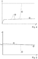
- Fig. 4 is shown schematically how the signal or a leakage current corresponding to the y-axis changes over time.
- the time course is shown here over many hours, for example over 160 hours as operating time.
- the solid curve shown A is a normal operation, the slight increase of the course A comes through a slow, flat calcification on the heater 11 or 111 or on the carrier 13 or 113 on the medium side.
- the dashed lines shown B represents the occurrence of a localized or small scale calcification or an aforementioned hot spot.
- the increase in the course of a few hours, for example, 1 hour to 5 hours to the maximum causes more than a doubling of the signal or leakage current at the maximum.
- the small-scale calcification has flaked off or has come off, which is why in this course B the leakage current or the signal just drops again and then again corresponds to the normal course A.
- the calcification has been completely or incompletely replaced here can not be distinguished on the basis of the waste alone. If the course B then continues parallel to the course A, but with an increased value, it can be assumed that the replacement was not complete. Although this can be recognized, countermeasures are not absolutely necessary.
- the dash-dotted curve C means, similar to the course B, forming a renewed localized or small scale calcification. Therefore, it should run in the rise area similar to the course B. However, the calcification does not dissolve here, a hot spot persists, which is why the leakage current or the signal continues to rise. If it reaches a limit value for the leakage current, in this case the limit value G L , which is, for example, slightly higher than four times the normal leakage current according to the curve A, then this is recognized as dangerous locally limited or small scale calcification with too high a temperature. Then the heat output at the single heating element 17 or at one of the heating elements 117a or 117b is correspondingly greatly reduced or even switched off in order to avoid damage. Via a signaling, not shown, the controller 29 can call an operator for maintenance or for descaling.
- Fig. 5 curves D and E are shown for the Wienleiterstrom I over the time t, again over a time axis of several hours.
- the continuous curve D corresponds to a normal operation, the slight drop of Schwarzleiterstroms represents a slow large scale or complete calcification on the medium side of the carrier 13 or 113 dar.
- a threshold value G H for the Wienleiterstrom is shown in broken lines, which may be, for example, 90% or 80% of the Schuleiterstroms at the beginning, here it is 90%. If this limit value G H is exceeded, the large-scale calcification on the medium side of the carrier 13 or 113 is too strong, consequently a heat loss through the water too low and the risk of overheating of the heater too large. This can therefore also be evaluated as a signal, so that the controller 29 reduces the heating power or the heater 11 or 111 turns off, including appropriate signaling to an operator. In the example shown this may be after about 10 to 20 hours.
- the dash-dotted line E is to show schematically how, at a certain point in time, the heating conductor current drops significantly more rapidly or faster when there is no water for heating and for removing the heat on the medium side of the carrier 13 or 113. This is the above-described case of empty cooking or dry-running in a PTC heating conductor. Then, the threshold value G H falls below quickly, which can be recognized by the controller 29 again. Since the drop of the Schuleiterstroms then but still significantly faster than the course D, just this special case of the reduced Schuleiterstroms can be determined. If at the same time the leakage current increases, for example, similar to the course C accordingly Fig.
- the controller 29 can not evaluate this as a case of a sudden localized or small scale calcification, also not as a case of large-scale calcification, but just as an event of empty cooking or drying. This can then be displayed in a special signaling to an operator. Furthermore, the controller 29 then turns off the heating device 11 or 111 in any case completely, since on the one hand there is otherwise the risk of damage and on the other hand heating makes no sense anyway.
- the heating conductor current falls, for example, within less than one minute, for example within 10 seconds to 30 seconds, so much that it falls below the limit value G H.
- the signal increases accordingly Fig. 4 ,
- the leakage current represented here by a corresponding voltage of the measuring device 30, in the second range behaves when switching on the heater 11 or 111 or the single heating element 17 or the two heating elements 117a and 117b.
- the solid curve is a normal operation, so that it can be seen that after one to two seconds the leakage current reaches a value that appears to be constant per se, with a course essentially corresponding to the curve A of FIG Fig. 4 equivalent.
- Is a hot spot or a localized or small scale calcification given already when switching on the heater 11 or 111 the leakage current increases according to the dashed curve to three times. However, if this calcification or hot spot does not become larger or worse, then a relatively stable state is also achieved, which manifests itself in the substantially constant course.
- the leakage current for the rise takes about 10 seconds, so it is also a very fast process.
- Fig. 7 It is shown how the Schuleiterstrom I behaves over time t (in minutes) when growing a large scale calcification.
- the Schuleiterstrom I is recorded on the left y-axis, on the right y-axis, the power P is recorded.
- the voltage U and the temperature T are recorded, these two without scaling, but with correct relative course.
- the time axis is not scaled in the area to the left of the double-dashed line as in the right, but within the two areas each already linear.
- the temperature T rises rather slowly until it reaches 65 ° C. This is here after about 18 minutes. Since the heating of the heating element due to the heating of the water now drops at a constant water temperature and thus the resulting proportion of change in the resistance of the heating element and thus the Schuleiterstroms I also eliminated, the waste is weaker or less. This is where the large-scale calcification begins. This starts even at a temperature of 65 ° C, well below that of boiling water. As a result of this large-scale calcification, the heating conductor current I drops further, in the example about 6% in 100 hours or 6000 minutes. The heating power drops accordingly, since the voltage U remains clearly identifiable.
Description
Die Erfindung betrifft eine Heizeinrichtung zum Erhitzen von Wasser sowie ein Verfahren zum Betrieb einer solchen Heizeinrichtung zum Erhitzen von Wasser.The invention relates to a heater for heating water and a method for operating such a heater for heating water.
Es ist aus der
Aus der
Aus der
Aus der
Der Erfindung liegt die Aufgabe zugrunde, eine eingangs genannte Heizeinrichtung sowie ein Verfahren zu ihrem Betrieb zu schaffen, mit denen Probleme des Standes der Technik gelöst werden können und es insbesondere möglich ist, Verkalkungen an einer Mediumseite des Trägers und somit eine potenzielle Gefahrenquelle zu erkennen bzw. eine Beschädigung der Heizeinrichtung zu verhindern.The invention has for its object to provide an aforementioned heating device and a method for their operation, with which problems of the prior art can be solved and it is in particular possible to recognize calcifications on a medium side of the carrier and thus a potential source of danger or to prevent damage to the heater.
Gelöst wird diese Aufgabe durch eine Heizeinrichtung mit den Merkmalen des Anspruchs 1 sowie ein Verfahren mit den Merkmalen des Anspruchs 5. Vorteilhafte sowie bevorzugte Ausgestaltungen der Erfindung sind Gegenstand der weiteren Ansprüche und werden im Folgenden näher erläutert. Dabei werden manche der Merkmale nur für die Heizeinrichtung oder nur für das Verfahren genannt. Sie sollen jedoch unabhängig davon sowohl für die Heizeinrichtung als auch für das Verfahren selbständig und unabhängig voneinander gelten können. Der Wortlaut der Ansprüche wird durch ausdrückliche Bezugnahme zum Inhalt der Beschreibung gemacht.This object is achieved by a heating device with the features of claim 1 and a method having the features of
Es ist vorgesehen, dass die Heizeinrichtung zum Erhitzen von Wasser, welches insbesondere durch einen Träger hindurchfließen soll bzw. an ihm vorbeifließen soll, vor allem an einer sogenannten Mediumseite des Trägers, einen solchen Träger aufweist. Auf diesem Träger ist mindestens ein Heizelement aufgebracht, welches einen einzigen Heizleiter aufweist oder mehrere hintereinander geschaltete Heizleiter aufweist. Vorteilhaft ist dies ein DickschichtHeizelement mit zwei elektrischen Anschlüssen, zwischen denen sich der einzige oder dessen einzelne hintereinander geschaltete bzw. aneinander anschließende Heizleiter erstrecken. So können die Heizleiter beispielsweise jeweils gerade Abschnitte des Heizelements sein, das insgesamt insbesondere einen mäanderförmigen Verlauf aufweisen kann. Es können auch mehrere solchermaßen ausgebildete Heizelemente vorgesehen sein, vorteilhaft mindestens zwei.It is provided that the heating device for heating water, which is intended to flow through a carrier in particular or should flow past it, especially on a so-called medium side of the carrier, such a carrier. On this support at least one heating element is applied, which has a single heat conductor or has a plurality of heating conductors connected in series. This is advantageously a DickschichtHeizelement with two electrical connections, between which extend the single or its individual successively connected or adjoining heating element. For example, the heating conductors may each be straight sections of the heating element, which may in particular have a meandering course in particular. It can also be provided a plurality of such trained heating elements, advantageously at least two.
Die Heizeinrichtung weist mindestens eine flächige Dielektrikumschicht auf, die im Wesentlichen die Heizleiter bzw. das Heizelement überdeckt. Die Dielektrikumschicht muss nicht zwingend direkt auf dem oder einem Heizelement aufliegen. Sie weist eigentlich elektrisch isolierende Eigenschaften auf, bei Temperaturen ab 200°C oder erst ab 300°C jedoch nimmt ihr elektrischer Widerstand ab. Derartige Dielektrikumschichten bestehen beispielsweise aus Glas oder Glaskeramik und sind in der vorgenannten
Eine Dielektrikumschicht ist auf beiden Seiten mit jeweils einer elektrisch leitfähigen Anschlussfläche versehen. Diese Anschlussflächen liegen also direkt an der Dielektrikumschicht an und können insbesondere einen durch die Dielektrikumschicht fließenden Strom bzw. sogenannten Leckstrom erfassen. Dabei können die elektrisch leitfähigen Anschlussflächen dieselbe Überdeckung haben, zumindest was eine äußere Kontur bzw. maximale Aufspannung der Fläche betrifft, abhängig davon, wie viele Dielektrikumschichten nebeneinander auf oder über den Heizelementen vorgesehen sind. Eine der elektrisch leitfähigen Anschlussflächen kann vorteilhaft auch vollflächig bzw. geschlossen ausgebildet sein.A dielectric layer is provided on both sides each with an electrically conductive pad. Thus, these pads are applied directly to the dielectric layer and can in particular detect a current flowing through the dielectric layer or so-called leakage current. In this case, the electrically conductive connection surfaces can have the same overlap, at least as far as an outer contour or maximum clamping of the surface is concerned, depending on how many dielectric layers are provided next to one another on or above the heating elements. One of the electrically conductive connection surfaces can advantageously also be formed over the entire surface or closed.
Mindestens eine der Anschlussflächen ist an eine Steuerung oder Messeinrichtung einer Steuerung zur Auswertung eines Leckstroms als Stromfluss durch die Dielektrikumschicht hindurch angeschlossen. So kann eben der Leckstrom überwacht werden hinsichtlich seines zeitlichen Verlaufs bzw. eines möglichen schnellen Anstiegs. Des Weiteren ist das Heizelement mit Messmitteln zur Überwachung eines Heizleiterstroms durch dieses Heizelement und somit durch seine sämtlichen Heizleiter verbunden. So kann eben auch der Heizleiterstrom überwacht bzw. ausgewertet werden, insbesondere hinsichtlich eines Abfalls aufgrund zunehmenden Widerstandes des Heizelements bei steigender bzw. wegen zu hoher Temperatur, wenn das Heizelement bei einer Ausgestaltung der Erfindung einen positiven Temperaturkoeffizienten seines Widerstands aufweist. Wenn das Heizelement bei einer anderen Ausgestaltung der Erfindung einen negativen Temperaturkoeffizienten seines Widerstands aufweist kann ein Anstieg des Heizleiterstroms aufgrund abnehmenden Widerstandes des Heizelements bei steigender bzw. wegen zu hoher Temperatur erkannt werden. Da die Steuerung bzw. Messeinrichtung den Heizleiterstrom überwacht und dazu auch die Spannung gemessen werden kann, lässt sich auch der Wärmetransfer in Form eines Wärmewiderstandes bewerten.At least one of the pads is connected to a controller or measuring device of a controller for evaluating a leakage current as a current flow through the dielectric layer. So just the leakage current can be monitored in terms of its time course or a possible rapid increase. Furthermore, the heating element with measuring means for monitoring a Heizleiterstroms by this heating element and thus connected by all its heating conductors. Thus, just the Heizleiterstrom can be monitored or evaluated, in particular with regard to a decrease due to increasing resistance of the heating element with increasing or too high temperature, if the heating element has a positive temperature coefficient of its resistance in one embodiment of the invention. If the heating element in another embodiment of the invention has a negative temperature coefficient of its resistance, an increase in the Heizleiterstroms be recognized due to decreasing resistance of the heating element with increasing or too high temperature. Since the control or measuring device monitors the heating conductor current and, in addition, the voltage can be measured, the heat transfer can also be evaluated in the form of a thermal resistance.
Somit ist es möglich, sowohl mittels des Leckstroms an der Dielektrikumschicht als auch mittels Überwachung des Heizleiterstroms die Temperaturverhältnisse am Heizelement bzw. an der Heizeinrichtung zu überwachen. Während eine Änderung des Heizleiterstroms zwar eher relativ langsam ist und sich auch insgesamt bei lokal begrenzter bzw. kleinflächiger Verkalkung nicht sehr stark ändert, da davon ja nur ein sehr kleiner Bereich des Heizelements betroffen ist, kann damit aber sozusagen eine über die Fläche gemittelte Temperatur und somit auch eine gemittelte Überhitzung an der Heizeinrichtung festgestellt werden. Das Feststellen einer lokal begrenzten bzw. kleinflächigen Überhitzung über Auswertung des Leckstroms an der Dielektrikumschicht ist zum Einen erheblich schneller und zum Anderen reicht hier sozusagen ein nur wenige Millimeter großer Bereich mit sehr hoher Temperatur, um hier den Leckstrom, der über die gesamte Fläche erfasst werden kann, schnell stark ansteigen zu lassen. Derartige Überhitzungen kommen in der Regel durch Verkalkungen zustande, wie nachfolgend noch näher erläutert wird, oder auch durch ein Leerkochen einer wassergefüllten Heizeinrichtung oder ein Trockengehen bei Einsatz in einer Pumpe. Es gibt auch sogenannte hot spots, die durch eine punktuelle oder kleinflächige, nicht vollständige Ablösung einer Verkalkung entstehen, wobei durch einen Zwischenraum zwischen der Mediumseite des Trägers und der Kalkschicht dann der Wärmetransfer zusätzlich behindert wird. Hier können gefährliche Überhitzungen auftreten, die zwar kleinflächig bzw. lokal sehr begrenzt sind, aber auch hier eine Beschädigung oder Zerstörung der Heizeinrichtung bewirken könnten.Thus, it is possible to monitor the temperature conditions on the heating element or on the heating device both by means of the leakage current at the dielectric layer and by monitoring the heating conductor current. While a change in the Heizleiterstroms is rather relatively slow and also not change very much in locally limited or small scale calcification, as this yes only a very small area of the heating element is affected, but so to speak, averaged over the surface temperature and Thus, an average overheating of the heater can be detected. The detection of a localized or small-area overheating on evaluation of the leakage current to the dielectric layer is on the one hand considerably faster and on the other hand, so to speak ranges only a few millimeters large area with very high temperature, here the leakage current, which are detected over the entire area can quickly increase sharply. Such overheating is usually caused by calcifications, as will be explained in more detail below, or by emptying a water-filled heater or dry running when used in a pump. There are also so-called hot spots, which are caused by a punctiform or small-scale, not complete detachment of a calcification, which is additionally hindered by a gap between the medium side of the carrier and the limestone layer, the heat transfer. Here, dangerous overheating may occur, although small or locally very limited, but also could cause damage or destruction of the heater.
Der Träger besteht vorteilhaft aus Metall. Auf ihm ist für einen Schichtaufbau eine Isolationsschicht aufgebracht, auf der wiederum das Heizelement oder die Heizelemente aufgebracht sind. Wie eingangs genannt werden Dickschichtheizelemente bevorzugt, beispielsweise mit genau einem oder mit mehreren Heizleitern in insgesamt erzeugter Mäanderform. Über bzw. auf das Heizelement oder die Heizelemente wiederum werden flächige Dielektrikumschichten aufgebracht, vorteilhaft als geschlossene Fläche. Eine flächige Dielektrikumschicht kann im Wesentlichen ein Rechteck bedecken. Eine Dielektrikumschicht wirkt auch als elektrische Isolation, zumindest im Bereich üblicher Betriebs-Temperaturen. Auf die Dielektrikumschicht wiederum kann mit im Wesentlichen derselben Fläche eine elektrisch leitfähige Anschlussfläche aufgebracht sein. Hier kann ein beliebiges elektrisch leitfähiges Material verwendet werden. Die andere elektrisch leitfähige Anschlussfläche an die Dielektrikumschicht wird dann von dem Heizelement bzw. den Heizelementen oder dessen Heizleitern gebildet. Im Betrieb der Heizeinrichtung werden diese an eine Betriebsspannung angeschlossen und von dem Heizleiterstrom durchflossen. Bei geringer werdender Isolationseigenschaften einer Dielektrikumschicht kann dann ein üblicherweise geringer Strom als Leckstrom durch die Dielektrikumschicht hindurch an die andere elektrisch leitfähige Anschlussfläche fließen. Durch den vorgenannten Anschluss an eine Steuerung kann dies erkannt werden.The carrier is advantageously made of metal. On it, an insulating layer is applied for a layer structure, on which in turn the heating element or the heating elements are applied. As mentioned above, thick-film heating elements are preferred, for example with exactly one or more heat conductors in a total generated meander shape. Be over or on the heating element or the heating elements turn planar dielectric layers applied, advantageously as a closed surface. A planar dielectric layer may substantially cover a rectangle. A dielectric layer also acts as electrical insulation, at least in the range of normal operating temperatures. In turn, an electrically conductive connection area can be applied to the dielectric layer with essentially the same area. Here, any electrically conductive material can be used. The other electrically conductive pad to the dielectric layer is then formed by the heating element or the heating elements or its heating conductors. During operation of the heater these are connected to an operating voltage and flows through the Heizleiterstrom. As the insulation properties of a dielectric layer become smaller, a usually small current can then flow as leakage current through the dielectric layer to the other electrically conductive connection area. This can be detected by the aforementioned connection to a controller.
Die Steuerung weist vorteilhaft einen Speicher auf, um Referenzwerte für die Heizelementtemperatur, Dielektrikumschicht-Signale oder einen Heizleiterstrom im normalen Betrieb abzuspeichern. Auch für abnormale Betriebszustände können Werte abgespeichert sein, insbesondere für lokal begrenzte bzw. kleinflächige Verkalkungen hinsichtlich der dann zu erwartenden Dielektrikumschicht-Signale oder eines Heizleiterstroms sowie Werte für vorgenannte hot spots und für flächige bzw. großflächige Verkalkung. Dies kann beispielsweise ein Grenzwert für den Dielektrikumstrom bzw. Leckstrom sein, der nicht überschritten werden darf bzw. bei dessen Erreichen die Heizeinrichtung abgeschaltet werden muss.The controller advantageously has a memory to store reference values for the heating element temperature, dielectric layer signals or a heating conductor current during normal operation. Values can also be stored for abnormal operating states, in particular for locally limited or small scale calcifications with regard to the then expected dielectric layer signals or a heating conductor current as well as values for the aforementioned hot spots and for surface or large-scale calcification. This can be, for example, a limit value for the dielectric current or leakage current, which may not be exceeded or, when it is reached, the heating device has to be switched off.
Eine Leistungsdichte des Heizelements kann vorteilhaft mindestens 30 W/cm2 oder mindestens 100 W/cm2 betragen. Besonders vorteilhaft kann die Leistungsdichte maximal 150 W/cm2 oder sogar 200 W/cm2 betragen. So ist eine schnell ansprechende und sehr leistungsfähige Heizeinrichtung bei kleinem Platzbedarf gegeben.A power density of the heating element may advantageously be at least 30 W / cm 2 or at least 100 W / cm 2 . Particularly advantageous, the power density can be a maximum of 150 W / cm 2 or even 200 W / cm 2 . So a fast responding and very powerful heater is given in a small footprint.
In Ausgestaltung der Erfindung greifen die Heizelemente ineinander bzw. sind verschränkt angeordnet, vorzugsweise mit Heizleitern als Abschnitte der Heizelemente, die gerade und parallel zueinander verlaufen. Somit können die Heizelemente vorteilhaft bifilar verlaufen, insbesondere in Mäanderform. Zwischen zwei parallelen Heizleitern eines Heizelements kann mindestens ein Heizleiter eines anderen Heizelements verlaufen, insbesondere parallel dazu.In an embodiment of the invention, the heating elements engage with one another or are arranged in an entangled manner, preferably with heat conductors as sections of the heating elements which run straight and parallel to one another. Thus, the heating elements can advantageously be bifilar, especially in meandering form. Between two parallel heating conductors of a heating element, at least one heating conductor of another heating element can run, in particular parallel thereto.
In alternativer Ausgestaltung der Erfindung verlaufen die Heizelemente zwar nahe beieinander, sind aber flächenmäßig getrennt bzw. greifen eben nicht ineinander. Jedes Heizelement nimmt sozusagen eine Fläche mit geschlossener Außenkontur ein, insbesondere eine Rechteckfläche oder eine Viereckfläche, in die kein Teil eines anderen Heizelements hineinragt.In an alternative embodiment of the invention, although the heating elements run close to each other, but are separated in terms of area or do not engage in each other. Each heating element takes so to speak, a surface with a closed outer contour, in particular a rectangular surface or a quadrangular surface into which no part of another heating element protrudes.
Vorteilhaft weist die Heizeinrichtung genau zwei oder drei Heizelemente auf. Zwei Heizelemente können gemäß der ersten vorgenannten Ausgestaltung der Erfindung ineinander greifen bzw. verschränkt angeordnet sein. Es kann ein zusätzliches drittes Heizelement vorgesehen sein, das dann aber flächenmäßig getrennt ist. Sind genau drei Heizelemente vorgesehen, so können sie vorteilhaft gemäß der zweiten vorgenannten Ausgestaltung der Erfindung alle drei nahe beieinander verlaufen und flächenmäßig getrennt sein.Advantageously, the heating device has exactly two or three heating elements. Two heating elements can be interlocked or interlocked according to the first embodiment of the invention mentioned above. It may be provided an additional third heating element, which is then separated in terms of area. If exactly three heating elements are provided, they can advantageously according to the second aforementioned embodiment of the invention all three run close to each other and be separated in terms of area.
Gemäß der Erfindung sind mindestens zwei elektrisch getrennte und unabhängig voneinander betreibbare Heizelemente auf dem Träger aufgebracht und es ist eine einzige flächige Dielektrikumschicht auf einer Seite der Heizelemente vorgesehen zum Anschluss an die Steuerung oder Messeinrichtung zur Erfassung eines Leckstroms, wobei die Dielektrikumschicht alle Heizelemente im Wesentlichen überdeckt. Die eine Anschlussfläche wird dann jeweils von den Heizelementen gebildet. Dadurch wird die flächenmäßige Unterscheidung der Heizelemente erreicht. Die andere Anschlussfläche, beispielsweise als Elektrode, kann die Dielektrikumschicht entweder vollflächig bedecken oder aber aufgeteilt in mehrere Anschlussflächen bzw. Teil-Elektroden sein, deren Aufteilung wiederum den Heizelementen entspricht bzw. diese im Wesentlichen mit ihrem Verlauf genau überdeckt. Dies weist den Vorteil auf, dass auch komplizierte Verläufe für die Heizelemente, insbesondere ineinander greifende Verläufe, mit den Anschlussflächen genauso nachgebildet werden können.According to the invention, at least two electrically separate and independently operable heating elements are mounted on the carrier and a single planar dielectric layer is provided on one side of the heating elements for connection to the control or measuring device for detecting a leakage current, wherein the dielectric layer substantially covers all the heating elements , The one pad is then formed in each case by the heating elements. As a result, the area discrimination of the heating elements is achieved. The other pad, for example as an electrode, can either cover the entire surface of the dielectric layer or be divided into a plurality of pads or partial electrodes, the distribution of which in turn corresponds to the heating elements or covers them substantially exactly with their course. This has the advantage that even complicated courses for the heating elements, in particular intermeshing courses, can also be simulated with the connection surfaces.
Bei dem erfindungsgemäßen Verfahren werden im Betrieb der Heizeinrichtung zum Erhitzen von Wasser sowohl der Heizleiterstrom durch das Heizelement bzw. durch die Heizleiter als auch ein Leckstrom durch die Dielektrikumschicht hindurch überwacht, wozu deren zeitliche Verläufe überwacht werden und unter Umständen auch abgespeichert werden als Betriebsprotokollierung. Dabei sind drei Fälle zu unterscheiden.In the method according to the invention, both the Heizleiterstrom by the heating element or by the heating element and a leakage through the dielectric layer are monitored during operation of the heater for heating water, including its temporal progressions are monitored and may also be stored as Betriebsprotokollierung. There are three cases to be distinguished.
In einem ersten Fall eines Heizleiters mit einem positiven Temperaturkoeffizienten, also eines PTC-Heizleiters, kann bei einem langsamen bzw. sozusagen zu langsamen Abfall des Heizleiterstroms eine großflächige Verkalkung an einer Mediumseite des Trägers erkannt werden bzw. kann ein solcher langsamer Abfall des Heizleiterstroms als eine solche großflächige Verkalkung definiert werden. Eine großflächige Verkalkung wächst langsam über die Betriebszeit auf, die Heizleitertemperatur steigt langsam mit der Betriebszeit wegen der geringer werdenden Wärmeabnahmefähigkeit und der Heizleiterstrom fällt ab. Daraus können verschiedene Maßnahmen folgen, wie beispielsweise eine Anzeige an einen Benutzer, dass eine Entkalkung bzw. Reinigung der Heizeinrichtung notwendig ist, oder eine vorübergehende temporäre Leistungsreduzierung mit gleichzeitiger Anzeige. Ein solcher langsamer Abfall des Heizleiterstroms liegt dann vor, wenn er um mindestens 2% in weniger als 100 Stunden abfällt. Unter Umständen kann er auch um mindestens 3% bis 5% in weniger als 100 Stunden abfallen, um als eine solche großflächige Verkalkung erkannt zu werden. Der Abfall des Heizleiterstroms wird bei annähernd gleicher Wassertemperatur bewertet, da der Heizleiterstrom beim Aufheizen des Wassers wegen der dabei ansteigenden Heizleitertemperatur ebenfalls fällt. Dies wird auch später anhand der
Es kann ein Temperatursensor an der Heizeinrichtung vorgesehen sein, vorteilhaft mit Abstand zu dem Heizelement bzw. dessen Heizleitern. Das kann ein kleiner Sensor sein, beispielsweise ein NTC. Der Abstand sollte so groß sein, dass der Temperatursensor nur die Temperatur am Träger und somit die des Wassers erfasst.A temperature sensor may be provided on the heating device, advantageously at a distance from the heating element or its heating conductors. This can be a small sensor, such as an NTC. The distance should be so large that the temperature sensor detects only the temperature at the carrier and thus the water.
In einem zweiten Fall eines Heizleiters mit einem negativen Temperaturkoeffizienten, also eines NTC-Heizleiters, kann bei einem langsamen bzw. sozusagen zu langsamen Anstieg des Heizleiterstroms eine großflächige Verkalkung an einer Mediumseite des Trägers erkannt werden bzw. kann ein solcher langsamer Anstieg des Heizleiterstroms als eine solche großflächige Verkalkung definiert werden. Es können aber ansonsten die gleichen Werte wie zuvor zum ersten Fall erläutert gelten, dass nämlich ein solcher langsamer Anstieg des Heizleiterstroms dann vorliegt, wenn er um mindestens 2% in weniger als 100 Stunden ansteigt. Unter Umständen kann er auch um mindestens 3% bis 5% in weniger als 100 Stunden ansteigen.In a second case of a heat conductor with a negative temperature coefficient, ie an NTC heat conductor, a large-scale calcification can be detected on a medium side of the carrier at a slow or so to slow rise of the Heizleiterstroms or can such a slow increase of the Heizleiterstroms as a such large scale calcification can be defined. Otherwise, however, the same values as previously explained for the first case may apply, namely that such a slow increase in the heating conductor current is present when it increases by at least 2% in less than 100 hours. It may also increase by at least 3% to 5% in less than 100 hours.
In einem dritten Fall kann ein zu schneller Anstieg des Leckstroms als eine lokal begrenzte bzw. kleinflächige Verkalkung bzw. ein vorgenannter hot spot an der Mediumseite des Trägers erkannt werden. Dies sollte der Steuerung auffallen, muss aber noch nicht zwingend zur Reduzierung der Heizleistung bzw. Abschalten der Heizeinrichtung führen. Ein solcher zu schneller Anstieg des Leckstroms liegt dann vor, wenn der Leckstrom um mindestens 30% in weniger als 20 Stunden ansteigt, unter Umständen auch um mindestens 30% in weniger als 5 Stunden oder um mindestens 50% in weniger als 10 Stunden. Als weitere Bedingung kann vorgesehen sein, dass ein absoluter Maximalwert bzw. Grenzwert für den Leckstrom überschritten wird, nicht nur damit eine solche lokal begrenzte bzw. kleinflächige Verkalkung oder ein hot spot an der Mediumseite des Trägers erkannt wird, sondern damit die Heizleistung zumindest reduziert oder sogar die Heizeinrichtung abgeschaltet wird. Dieser absolute Grenzwert kann insbesondere mindestens 200% des Leckstroms betragen, der zu Beginn des Betriebs der Heizeinrichtung im sauberen Zustand bzw. ohne Verkalkung der Mediumseite des Trägers vorliegt. Es kann auch ein absoluter Grenzwert für den Leckstrom vorgesehen werden. So kann vorgesehen sein, dass der Leckstrom maximal 20 mA oder 30mA betragen darf, ansonsten erfolgt eine Abschaltung wegen eines hot spot.In a third case, too rapid a rise in the leakage current can be detected as a locally limited or small-scale calcification or an aforementioned hot spot on the medium side of the carrier. This should be noticeable to the controller, but does not necessarily have to lead to a reduction of the heating power or shutdown of the heater. Such a too rapid increase in leakage current occurs when the leakage current increases by at least 30% in less than 20 hours, possibly by at least 30% in less than 5 hours or by at least 50% in less than 10 hours. As a further condition can be provided that an absolute maximum value or limit value for the leakage current is exceeded, not only so that such a localized or small scale calcification or hot spot on the medium side of the carrier is detected, but thus at least reduced or the heating power even the heater is turned off. This absolute In particular, the limit value may be at least 200% of the leakage current which is present at the beginning of the operation of the heating device in the clean state or without calcification of the medium side of the carrier. It is also possible to provide an absolute limit value for the leakage current. Thus it can be provided that the leakage current may amount to a maximum of 20 mA or 30 mA, otherwise a shutdown occurs because of a hot spot.
Hier können mehrere Heizelemente nacheinander einzeln betrieben werden, wobei in jedem einzelnen Betriebsfall der Leckstrom an der mindestens einen Dielektrikumschicht über dem jeweils gerade betriebenen Heizelement erfasst wird und unter Umständen auch abgespeichert wird als Betriebsprotokollierung. Dabei sind zwei Möglichkeiten zu unterscheiden. Bei einer ersten Möglichkeit, dass der Leckstrom bei dem einzelnen Betrieb der Heizelemente jeweils gleich ist, insbesondere um maximal 10% bis 20% unterschiedlich ist, wird eine großflächige Verkalkung an der Mediumseite des Trägers erkannt bzw. dies wird als großflächige Verkalkung gewertet. Bei einer zweiten Möglichkeit, dass der Leckstrom bei dem einzelnen Betrieb der Heizelemente unterschiedlich ist bzw. um mindestens 10% unterschiedlich ist, insbesondere um mindestens 30% unterschiedlich ist, wird eine lokal begrenzte bzw. kleinflächige Verkalkung an der Mediumseite des Trägers im Bereich des Heizelements mit dem höheren Leckstrom erkannt bzw. es wird ein vorgenannter hot spot erkannt.Here, several heating elements can be operated one after the other individually, wherein in each individual operating case the leakage current is detected at the at least one dielectric layer above the heating element currently being operated and under certain circumstances is also stored as operation logging. There are two ways to differentiate. In a first possibility that the leakage current in the individual operation of the heating elements is the same in each case, in particular by a maximum of 10% to 20% is different, a large-scale calcification on the medium side of the carrier is detected or this is considered as large-scale calcification. In a second possibility that the leakage current in the individual operation of the heating elements is different or at least 10% different, in particular by at least 30% different, a localized or small scale calcification on the medium side of the carrier in the region of the heating element detected with the higher leakage current or it is detected an aforementioned hot spot.
In weiterer Ausgestaltung der Erfindung kann vorgesehen sein, dass für den Fall, dass eine großflächige Verkalkung an der Mediumseite des Trägers erkannt worden ist, eine optische und/oder akustische Signalisierung an eine Bedienperson erfolgt. Damit sollte mitgeteilt werden, dass eine Reinigung bzw. Entkalkung der Heizeinrichtung bzw. des mit der Heizeinrichtung versehenen Geräts erfolgen sollte. In diesem Fall kann der Betrieb der Heizeinrichtung noch problemlos weitergehen, entweder mit voller Heizleistung oder aber zumindest mit reduzierter Heizleistung. Es kann auch vorgesehen sein, dass bei Erreichen eines ersten Grenzwerts für eine großflächige Verkalkung die Heizleistung um 20% bis 50% reduziert werden muss, aber zumindest die Heizeinrichtung noch weiter betrieben werden kann. Bei Erreichen eines zweiten Grenzwerts kann dann entweder der Betrieb nur noch mit geringer Heizleistung weitergeführt werden, beispielsweise maximal 20% bis 30%, oder aber die Heizeinrichtung wird ganz abgeschaltet. Eine Reduzierung der Leistung der Heizeinrichtung kann hier gleichmäßig auf die einzelnen Heizelemente verteilt werden wenn mehrere davon vorgesehen sind.In a further embodiment of the invention can be provided that in the event that a large-scale calcification has been recognized on the medium side of the carrier, a visual and / or acoustic signaling to an operator. This should be reported that a cleaning or descaling of the heater or provided with the heater device should be made. In this case, the operation of the heater can still go on easily, either with full heating power or at least reduced Heating capacity. It can also be provided that when a first limit value for a large-scale calcification has been reached, the heating power has to be reduced by 20% to 50%, but at least the heating device can continue to be operated. When a second limit value is reached, either the operation can then be continued only with low heating power, for example a maximum of 20% to 30%, or else the heating device is completely switched off. A reduction in the power of the heater can be evenly distributed to the individual heating elements if several of them are provided.
Für den Fall, dass eine lokal begrenzte bzw. kleinflächige Verkalkung oder ein hot spot erkannt worden ist durch zu schnellen starken Anstieg des Leckstroms wie zuvor erläutert, kann die Heizleistung des davon betroffenen Heizelements stark reduziert werden. Insbesondere kann dieses Heizelement oder, alternativ die gesamte Heizeinrichtung, auch sofort abgeschaltet werden. Dies gilt insbesondere dann, wenn, wie zuvor erläutert, auch ein absoluter Maximalwert bzw. Grenzwert für den Leckstrom überschritten worden ist. Ansonsten besteht nämlich die Gefahr einer nachhaltigen Beschädigung oder sogar Zerstörung der Heizeinrichtung nicht nur im Bereich dieses Heizelements, sondern sogar der gesamten Heizeinrichtung. Dann ist es möglich, dass nach einer Wartezeit von 2 Sekunden bis 20 Sekunden die Heizeinrichtung bzw. das betroffene Heizelement wieder eingeschaltet wird, vorteilhaft mit derselben Heizleistung wie zuvor bzw. sofort mit voller Heizleistung, also sehr schnell. Durch eine schnelle Temperaturänderung kann ein Abplatzen einer lokal begrenzten bzw. kleinflächigen Verkalkung bewirkt werden, evtl. auch beim hot spot. Dieser Vorgang kann unter Umständen auch mehrfach wiederholt werden, beispielsweise zweimal bis fünfmal oder sogar zehnmal. Erst wenn dann bei der Überwachung des Leckstroms und dessen erneutem sehr schnellen starken Anstieg sowie evtl. eines Unterschieds zwischen den einzelnen Heizelementen erkannt wird, dass immer noch eine lokal begrenzte bzw. kleinflächige Verkalkung oder der hot spot an der Heizeinrichtung bzw. dem betroffenen Heizelement vorliegt, welche dann offensichtlich nicht zum Abplatzen gebracht worden ist bzw. entfernt werden kann, sollte die Heizleistung an diesem Heizelement wie vorbeschrieben reduziert werden und dieses Heizelement oder unter Umständen sogar die gesamte Heizeinrichtung abgeschaltet werden zusammen mit einer entsprechenden Fehleranzeige an eine Bedienperson. Das Abplatzen bzw. Entfernen einer solchen lokal begrenzten bzw. kleinflächigen Verkalkung oder eines hot spot kann nämlich dadurch erkannt werden, dass bei erneutem Einschalten der Heizeinrichtung, insbesondere mit zuvor eingestellter bzw. voller Heizleistung, nicht sofort wieder ein schneller starker Anstieg des Leckstroms erfolgt.In the event that a localized or small-scale calcification or a hot spot has been recognized by rapid increase of the leakage current as explained above, the heating power of the affected heating element can be greatly reduced. In particular, this heating element or, alternatively, the entire heater can also be switched off immediately. This applies in particular if, as explained above, an absolute maximum value or limit value for the leakage current has also been exceeded. Otherwise, there is the risk of sustained damage or even destruction of the heater not only in the area of this heating element, but even the entire heater. Then it is possible that after a waiting time of 2 seconds to 20 seconds, the heater or the affected heating element is turned on again, advantageously with the same heating power as before or immediately with full heating power, so very fast. By a rapid change in temperature, a flaking of a localized or small scale calcification can be effected, possibly even at the hot spot. Under certain circumstances, this process can also be repeated several times, for example twice to five times or even ten times. Only when it is detected in the monitoring of the leakage current and its renewed very rapid increase and possibly a difference between the individual heating elements, that there is still a localized or small scale calcification or the hot spot on the heater or the heating element concerned , which then obviously has not been caused to flake or should be removed, the heating power should be reduced to this heating element as described above and this heating element or possibly even the entire heater are switched off together with a corresponding error message to an operator. The flaking or removal of such a localized or small-scale calcification or a hot spot can namely be recognized by the fact that when the heater is switched on again, in particular with previously set or full heating power, a rapid increase in the leakage current does not take place immediately.
Bei mehreren Heizelementen kann in einem Fall nach Erkennen einer lokal begrenzten bzw. kleinflächigen Verkalkung an der Mediumseite des Trägers im Bereich eines Heizelements die Leistung dieses Heizelements reduziert werden oder es kann ganz abgeschaltet werden. Mindestens ein weiteres Heizelement wird dann mit unveränderter Leistung weiter betrieben, da es bei diesem ja gefahrlos geht. In dem anderen Fall, dass eine großflächige Verkalkung an der Mediumseite des Trägers erkannt wird, kann das dort befindliche Heizelement oder allgemein ein Heizelement mit mindestens einem weiteren Heizelement in Serie geschaltet werden um die Heizeinrichtung mit insgesamt reduzierter Leistung weiter zu betreiben. Dies können allgemein zwei unterschiedliche Fälle eines Notfallbetriebs sein.In the case of several heating elements, the performance of this heating element can be reduced or it can be switched off completely in one case after recognizing a locally limited or small scale calcification on the medium side of the carrier in the region of a heating element. At least one further heating element is then operated with unchanged performance, since it is safe in this case. In the other case that a large-scale calcification on the medium side of the carrier is detected, the heating element located there or generally a heating element with at least one further heating element can be connected in series to continue to operate the heater with a reduced overall power. These can generally be two different cases of emergency operation.
Zur Einstellung unterschiedlicher Leistungen an der Heizeinrichtung können die einzelnen Heizelemente unterschiedlich zusammengeschaltet werden, vorzugsweise können sie seriell oder parallel oder einzeln betrieben werden. Vorteilhaft weisen die Heizelemente unterschiedliche Leistungswerte auf. Sie können dann nach Leistungsabstufung seriell, einzeln oder für maximale Leistung parallel geschaltet werden.To set different power to the heater, the individual heating elements can be interconnected differently, preferably they can be operated serially or in parallel or individually. Advantageously, the heating elements have different power values. They can then be switched in parallel, by power, serial, single, or for maximum power.
In weiterer Ausgestaltung der Erfindung kann vorgesehen sein, dass für den Fall, dass weder die Überwachung des Heizleiterstroms einen langsamen Abfall oder Anstieg noch die Überwachung des Leckstroms durch die Dielektrikumschicht einen schnellen starken Anstieg innerhalb Sekunden oder innerhalb 1 Minute zeigen, aber zu einem bestimmten Zeitpunkt sowohl ein starker Anstieg des Leckstroms als auch ein relativ schneller Abfall oder entsprechender Anstieg des Heizleiterstroms zur gleichen Zeit auftreten, der Fall eines Leerkochens eines mit der Heizeinrichtung versehenen Behälters oder ein Trockengehen bei Einsatz der Heizeinrichtung in einer Pumpe erkannt wird. Ein solches Leerkochen bzw. die daraus resultierende Überhitzung betrifft üblicherweise die gesamte Heizeinrichtung bzw. den gesamten Träger. Deswegen kann hier auch kein unterschiedliches Verhalten von mehreren Heizelementen festgestellt werden zusammen mit dem vorgenannten schnellen und in etwa gleichen Anstieg des Leckstroms. In diesem Fall fällt bei einem PTC-Heizleiter nämlich aufgrund der relativ schnellen Temperaturerhöhung der gesamten Heizeinrichtung der Heizleiterstrom deutlich schneller ab bzw. er steigt bei einem NTC-Heizleiter deutlich schneller an als bei einer großflächigen Verkalkung. Es wird ja keine Wärme mehr abgenommen. Des Weiteren steigt auch der Leckstrom an, allerdings mit quasi gleicher Geschwindigkeit wie der Heizleiterstrom abfällt bzw. ansteigt, da es ja keine lokale Überhitzung ist, sondern eine großflächige bzw. vollflächige. In diesem Fall sollte die gesamte Heizeinrichtung sofort abgeschaltet werden, da im Übrigen ein weiterer Betrieb auch keinen Sinn macht und vor allem die Gefahr einer Beschädigung zu groß ist. Zusätzlich sollte ein entsprechendes Signal an eine Bedienperson ausgegeben werden.In a further embodiment of the invention can be provided that in the event that neither the monitoring of the Heizleiterstroms a slow drop or increase nor the monitoring of the leakage current through the dielectric layer show a rapid sharp increase within seconds or within 1 minute, but at a certain time both a large increase in the leakage current and a relatively rapid decrease or increase in the heating conductor current occur at the same time, the case of emptying a heater provided container or dry running when the heater is used in a pump is detected. Such an empty cooking or the resulting overheating usually affects the entire heating device or the entire carrier. Therefore, no different behavior of several heating elements can be determined here together with the aforementioned rapid and approximately equal increase in the leakage current. In this case, because of the relatively rapid increase in the temperature of the entire heating device, the heating conductor current drops significantly faster in a PTC heating conductor, and it increases significantly faster in an NTC heating conductor than in a large-scale calcification. There is no heat removed. Furthermore, the leakage current increases, but with almost the same speed as the Heizleiterstrom drops or increases, since it is not a local overheating, but a large area or full-surface. In this case, the entire heater should be shut down immediately, because otherwise a further operation makes no sense and above all the risk of damage is too great. In addition, a corresponding signal should be output to an operator.
In einer weiteren bevorzugten Ausgestaltung der Erfindung wird das Verfahren zum Betrieb einer erfindungsgemäßen Heizeinrichtung einer Geschirrspülmaschine eingesetzt, wobei vorteilhaft die Geschirrspülmaschine eine Steuerung für den Betrieb einer Wasserenthärtung in der Geschirrspülmaschine aufweist. Es kann vorgesehen sein, dass zu Beginn des Betriebs der Geschirrspülmaschine, also nach der ersten Inbetriebnahme, die Wasserenthärtung in der Geschirrspülmaschine abgesenkt wird für eine niedrigere Wasserenthärtung. Diese kann solange abgesenkt werden oder im abgesenkten Zustand betrieben werden, bis über einen entsprechenden langsamen Abfall oder Anstieg des Heizleiterstroms auf zuvor erläuterte Art und Weise eine großflächige Verkalkung an einer Mediumseite des Trägers erkannt wird. Als Reaktion darauf kann eine Signalisierung an eine Bedienperson erfolgen, dass der Träger bzw. die Heizeinrichtung manuell zu entkalken ist. Die Steuerung der Geschirrspülmaschine kann die Wasserenthärtung automatisch wieder erhöhen, insbesondere kurzzeitig stark erhöhen und dann wieder etwas absenken, um dann mit verringerter Wasserenthärtung weiterzuarbeiten. Für den Einsatz in einer Geschirrspülmaschine kann eine solche erfindungsgemäße Heizeinrichtung beispielsweise in eine Pumpe zum Erhitzen und zum Fördern des Wassers in der Geschirrspülmaschine eingebaut werden, wie dies beispielsweise die
Diese und weitere Merkmale gehen außer aus den Ansprüchen auch aus der Beschreibung und den Zeichnungen hervor, wobei die einzelnen Merkmale jeweils für sich allein oder zu mehreren in Form von Unterkombinationen bei einer Ausführungsform der Erfindung und auf anderen Gebieten verwirklicht sein und vorteilhafte sowie für sich schutzfähige Ausführungen darstellen können, für die hier Schutz beansprucht wird. Die Unterteilung der Anmeldung in einzelne Abschnitte sowie Zwischen-Überschriften beschränken die unter diesen gemachten Aussagen nicht in ihrer Allgemeingültigkeit.These and other features will become apparent from the claims but also from the description and drawings, wherein the individual features each alone or more in the form of sub-combinations in an embodiment of the invention and in other fields be realized and advantageous and protectable Represent embodiments for which protection is claimed here. The subdivision of the application into individual sections as well as intermediate headings does not restrict the general validity of the statements made thereunder.
Ausführungsbeispiele der Erfindung sind in den Zeichnungen schematisch dargestellt und werden im Folgenden näher erläutert. In den Zeichnungen zeigen:
- Fig. 1
- eine Ausführung einer nicht von der Erfindung umfassten Heizeinrichtung mit einem einzigen Heizelement mit Schichtaufbau in Explosionsdarstellung,
- Fig. 2
- eine Ausführung einer erfindungsgemäßen Heizeinrichtung mit zwei Heiz-elementen in seitlicher Darstellung,
- Fig. 3
- eine Draufsicht auf die Heizeinrichtung aus
Fig. 2 , - Fig. 4
bis 6 - verschiedene Diagramme mit Verläufen des Leckstroms und des Heizleiter-stroms und
- Fig. 7
- ein Diagramm für einen Verlauf des Heizleiterstroms und der Leistung beim langsamen großflächigen Verkalken.
- Fig. 1
- an embodiment of a not included in the invention heater with a single heating element with layer structure in exploded view,
- Fig. 2
- an embodiment of a heating device according to the invention with two heating elements in a lateral view,
- Fig. 3
- a plan view of the heater off
Fig. 2 . - 4 to 6
- different diagrams with curves of the leakage current and the heating conductor current and
- Fig. 7
- a diagram for a course of Heizleiterstroms and the performance of slow large-scale calcification.
In
Auf der ersten Isolationsschicht 15 ist ein einziges Heizelement 17 mit mäanderförmigem Verlauf aufgebracht, das aus einzelnen hintereinander bzw. seriell geschalteten Heizleitern 17' besteht. Diese sind weitgehend gerade und durch gebogene Abschnitte verbunden. Es könnte aber auch ein einziger Heizleiter vorgesehen sein, der auch erheblich breiter ist als die hier dargestellten schmalen Heizleiter 17', siehe hierzu auch die
Über dem Heizelement 17 ist großflächig eine Dielektrikumschicht 20 aufgebracht, die glasartig bzw. eine Glasschicht sein kann. Die Dielektrikumschicht 20 verschließt sozusagen die Heizeinrichtung 11 bzw. isoliert das Heizelement 17 und verschließt dieses sowie den Schichtaufbau, insbesondere gegen schädliche oder aggressive Umwelteinflüsse. Zur elektrischen Kontaktierung an das Heizelement 17 bzw. dessen Heizleiterkontakte 18 weist die Dielektrikumschicht 20 Fenster 21 genau über den Heizleiterkontakten 18 auf für ein an sich bekanntes Durchkontaktieren.Over the
Auf der Dielektrikumschicht 20 ist eine Elektrode 24 als elektrisch leitfähige Anschlussfläche aufgebracht, und zwar in Form einer großflächigen Schicht. Diese ist hier genau so groß wie der Träger 13 und die Isolationsschicht 15. Die Elektrode 24 sollte nicht direkt auf den Träger 13 oder das Heizelement 17 überlappen, da sie von Träger 13 und Heizelement 17 isoliert sein muss. Auf der Elektrode 24 kann sich eine weitere Abdeckung bzw. Isolationsschicht befinden, muss aber nicht. Sie weist an den Ecken zwei Ausschnitte 25 auf, die zusammen mit den darunterliegenden Fenstern 21 in der Dielektrikumschicht 20 eine zuvor beschriebene Kontaktierung an die Heizleiterkontakte 18 ermöglichen. Das Heizelement 17 bzw. dessen Heizleiter 17' bilden die andere bzw. erste Anschlussfläche.On the
Dargestellt ist auch eine Steuerung 29 mit Leistungsversorgung für das Heizelement 17. Die Steuerung 29 weist einen Speicher 29' auf. Dies ist aus dem Stand der Technik bekannt und braucht nicht näher erläutert zu werden. Des Weiteren ist eine Messeinrichtung 30 dargestellt, die einerseits mit der Elektrode 24 über einen Elektrodenkontakt 26 und andererseits mit dem Heizelement 17 verbunden ist. Wie zuvor erläutert worden ist, ändern sich die dielektrischen bzw. resistiven Eigenschaften der zweiten Dielektrikumschicht 20 mit der Temperatur, und der von der Messeinrichtung 30 erfasste Strom bzw. Ableitstrom ändert sich entsprechend bzw. steigt an mit ansteigender Temperatur. Die Messeinrichtung erfasst dann diese Änderung der Eigenschaften der Dielektrikumschicht 20 zwischen Heizelement 17 und Elektrode 24.Shown is also a
In
An der Mediumseite 113 besteht die Gefahr einer Verkalkung der Heizeinrichtung 111 mit den genannten Risiken einer Überhöhung der Temperatur und Beschädigung oder sogar Zerstörung einzelner Heizelemente 117 oder der Heizeinrichtung 111. Deswegen ist gerade bei den hier genannten hohen Leistungsdichten darauf zu achten, dass dies nicht passiert.On the
An die Heizeinrichtung 111 sind entsprechend der
In der
Beide Heizelemente 117a und 117b weisen die gleiche Länge und jeweils vier Längsabschnitte auf. Beide Heizelemente 117a und 117b weisen auch an zwei nebeneinanderliegenden Längsabschnitten auf bekannte Art und Weise Unterbrechungen durch Kontaktbrücken auf. Damit kann lokal die Heizleistung etwas gesenkt werden. Eine elektrische Kontaktierung der Heizelemente 117a und 117b erfolgt über die einzelnen Kontaktfelder 118a und 118b sowie ein gemeinsames Kontaktfeld 118'. Schematisch zu erkennen ist auch ein Steckanschluss 122, der auf den Kontaktfeldern 118 bzw. auf den Träger 112 aufgebracht ist, vorteilhaft gemäß der
Es ist leicht vorstellbar, wie auch noch ein drittes Heizelement beispielsweise separat neben den beiden Heizelemente 117a und 117b verlaufen könnte, oder aber in den mittigen Zwischenraum zwischen den inneren Heizleitern des Heizelements 117a eingreifen könnte. Unter Umständen könnte es auch an beiden äußeren Heizleitern des Heizelements 117a entlang laufen und wäre somit auch quasi verschränkt.It is easy to imagine how even a third heating element could for example run separately next to the two
Auf die Heizelemente 117a und 117b ist eine einzige flächige Dielektrikumschicht 119 aus einem geeigneten Material aufgebracht, hier dargestellt durch die Kreuzschraffierung. Sie überdeckt beide Heizelemente 117a und 117b vollständig und reicht bis an den Rand des Trägers 112 oder kurz davor.On the
Auf die Dielektrikumschicht 119 wiederum ist eine Elektrodenfläche 121 aufgebracht, und zwar hier als vollflächige Elektrode. Somit ist zwar keine separate Temperaturerfassung bzw. Erfassung einer Verkalkung möglich mit Unterscheidung in verschiedene Flächen, aber ein einfacher Aufbau gewährleistet. Die flächenmäßige Unterscheidung erfolgt ja durch den vorbeschriebenen getrennten einzelnen Betrieb der Heizelemente 117a und 117b. Die Elektrodenfläche 121 ist auf hier nicht dargestellte Art und Weise elektrisch kontaktiert, vorteilhaft mittels des Steckanschlusses 122.In turn, an
Anhand der
In einer zweiten Ausgestaltung könnte auch die Dielektrikumschicht in zwei bzw. entsprechend viele Teil-Dielektrikumschichten aufgeteilt sein mit einem Verlauf entsprechend dem darunterliegenden Heizelement. Dann ist auch pro Teil-Dielektrikumschicht eine korrespondierend ausgebildete Teil-Elektrodenfläche aufgebracht. Hierbei wäre aber der Fertigungsaufwand erkennbar erheblich höher.In a second embodiment, the dielectric layer could also be divided into two or correspondingly many partial dielectric layers with a profile corresponding to the underlying heating element. Then, a correspondingly formed partial electrode surface is also applied per partial dielectric layer. Here, however, the production cost would be noticeably higher.
In der
Der gestrichelt dargestellte Verlauf B stellt das Auftreten einer lokal begrenzten bzw. kleinflächigen Verkalkung bzw. eines vorgenannten hot spot dar. Das Ansteigen im Verlauf einiger Stunden, beispielsweise 1 Stunde bis 5 Stunden bis zum Maximum, bewirkt mehr als eine Verdopplung des Signals bzw. Leckstroms am Maximum. Dann ist beim Verlauf B die kleinflächige Verkalkung abgeplatzt bzw. hat sich abgelöst, weswegen bei diesem Verlauf B der Leckstrom bzw. das Signal eben wieder abfällt und dann wieder dem normalen Verlauf A entspricht. Ob die Verkalkung hier vollständig oder unvollständig abgelöst worden ist kann aufgrund des Abfalls alleine nicht unterschieden werden. Sollte der Verlauf B dann parallel zum Verlauf A weiterlaufen, aber mit erhöhtem Wert, so ist davon auszugehen, dass die Ablösung nicht vollständig war. Dies kann zwar erkannt werden, Gegenmaßnahmen sind jedoch nicht unbedingt notwendig.The dashed lines shown B represents the occurrence of a localized or small scale calcification or an aforementioned hot spot. The increase in the course of a few hours, for example, 1 hour to 5 hours to the maximum causes more than a doubling of the signal or leakage current at the maximum. Then, during the course B, the small-scale calcification has flaked off or has come off, which is why in this course B the leakage current or the signal just drops again and then again corresponds to the normal course A. Whether the calcification has been completely or incompletely replaced here can not be distinguished on the basis of the waste alone. If the course B then continues parallel to the course A, but with an increased value, it can be assumed that the replacement was not complete. Although this can be recognized, countermeasures are not absolutely necessary.
Der strichpunktiert dargestellte Verlauf C bedeutet, ähnlich wie beim Verlauf B, das Bilden einer erneuten lokal begrenzten bzw. kleinflächigen Verkalkung. Deswegen sollte sie im Anstiegsbereich ähnlich verlaufen wie beim Verlauf B. Allerdings löst sich hier die Verkalkung nicht ab, ein hot spot besteht weiter, weswegen der Leckstrom bzw. das Signal weiter ansteigt. Wenn es einen Grenzwert für den Leckstrom erreicht, hier den Grenzwert GL, der beispielsweise etwas höher liegt als das Vierfache des normalen Leckstroms entsprechend dem Verlauf A, so wird dies als gefährliche lokal begrenzte bzw. kleinflächige Verkalkung erkannt mit einer zu hohen Temperatur. Dann wird die Heizleistung am einzigen Heizelement 17 oder an einem der Heizelemente 117a oder 117b entsprechend stark reduziert oder dieses sogar abgeschaltet, um eine Beschädigung zu vermeiden. Über eine nicht dargestellte Signalisierung kann die Steuerung 29 eine Bedienperson zur Wartung bzw. zur Entkalkung aufrufen.The dash-dotted curve C means, similar to the course B, forming a renewed localized or small scale calcification. Therefore, it should run in the rise area similar to the course B. However, the calcification does not dissolve here, a hot spot persists, which is why the leakage current or the signal continues to rise. If it reaches a limit value for the leakage current, in this case the limit value G L , which is, for example, slightly higher than four times the normal leakage current according to the curve A, then this is recognized as dangerous locally limited or small scale calcification with too high a temperature. Then the heat output at the
In
Der strichpunktiert dargestellte Verlauf E soll schematisch zeigen, wie ab einem bestimmten Zeitpunkt der Heizleiterstrom deutlich stärker bzw. schneller abfällt, wenn an der Mediumseite des Trägers 13 oder 113 kein Wasser zum Erhitzen und zur Abnahme der Wärme vorhanden ist. Dies ist der vorbeschriebene Fall des Leerkochens bzw. des Trockengehens bei einem PTC-Heizleiter. Dann wird der Grenzwert GH rasch unterschritten, was von der Steuerung 29 wieder erkannt werden kann. Da der Abfall des Heizleiterstroms dann aber noch erheblich schneller erfolgt als beim Verlauf D, kann eben dieser spezielle Fall des verringerten Heizleiterstroms festgestellt werden. Falls gleichzeitig auch der Leckstrom ansteigt, beispielsweise ähnlich wie beim Verlauf C entsprechend
Im Fall eines solchen Leerkochens bzw. Trockengehens fällt der Heizleiterstrom beispielsweise innerhalb weniger als einer Minute, beispielsweise innerhalb von 10 Sekunden bis 30 Sekunden, so stark ab, dass er den Grenzwert GH unterschreitet. Entsprechend schnell steigt dann auch das Signal entsprechend
In der
In
Nach dem Einschalten bei t=0 steigt der Heizleiterstrom I mit der ansteigenden Spannung auf einen Maximalwert an, die Leistung P auch, beispielsweise innerhalb weniger Sekunden, dann fallen beide ab. Die Temperatur T steigt eher langsam an, bis sie 65°C erreicht hat. Dies ist hier nach etwa 18 Minuten. Da die Erwärmung des Heizelements aufgrund der Erwärmung des Wassers nun bei konstanter Wassertemperatur wegfällt und somit der dadurch entstehende Anteil der Veränderung des Widerstands des Heizelements und somit des Heizleiterstroms I auch wegfällt, wird dessen Abfall schwächer bzw. geringer. Hier beginnt die großflächige Verkalkung. Diese startet also auch bereits bei einer Temperatur, die mit 65°C deutlich unter der von kochendem Wasser liegt. Durch diese entstehende großflächige Verkalkung fällt der Heizleiterstrom I weiter ab, im Beispiel etwa 6% in 100 Stunden bzw. 6000 Minuten. Die Heizleistung fällt entsprechend ab, da die Spannung U ja erkennbar gleich bleibt.After switching on at t = 0, the Heizleiterstrom I increases with the rising voltage to a maximum value, the power P also, for example within a few seconds, then both fall off. The temperature T rises rather slowly until it reaches 65 ° C. This is here after about 18 minutes. Since the heating of the heating element due to the heating of the water now drops at a constant water temperature and thus the resulting proportion of change in the resistance of the heating element and thus the Heizleiterstroms I also eliminated, the waste is weaker or less. This is where the large-scale calcification begins. This starts even at a temperature of 65 ° C, well below that of boiling water. As a result of this large-scale calcification, the heating conductor current I drops further, in the example about 6% in 100 hours or 6000 minutes. The heating power drops accordingly, since the voltage U remains clearly identifiable.
Claims (13)
- Heating device (111) for heating water (5), wherein- the heating device (111) has a carrier (112),- at least one heating element (117) is applied to the carrier,- the heating element (117) has precisely one heating conductor or a plurality of heating conductors which are connected one behind the other,- the heating device (111) has at least one flat dielectric layer (119) which substantially covers the at least one heating element (117),- an electrically conductive connection area (121) is in each case provided on both sides of the dielectric layer (119),- at least one of the connection areas (121) is connected to a controller or measuring device for detecting a leakage current as current flow through the dielectric layer (191),
characterized in that- the at least one heating element (117) is connected to measuring means for monitoring a heating conductor current through the heating element,- at least two heating elements (117a, 117b) which are electrically separated and can be operated independently of one another are applied to the carrier (112),- a single flat dielectric layer (119) is provided on one side of the heating elements (117a, 117b) for the purpose of connection to the controller or measuring device for detecting a leakage current,- the dielectric layer (119) substantially covers the heating elements (117a, 117b). - Heating device according to claim 1, characterized in that an insulating layer (115) is applied to the carrier (112), a heating element (117) being applied to the said insulating layer, wherein the flat dielectric layer (119) is applied over the heating element and covers, in particular, a closed area, such as substantially a rectangle, wherein an electrically conductive connection area (121) is applied to the dielectric layer, once again with substantially the same area, wherein the other electrically conductive connection area is formed by the heating element (117).
- Heating device according to claim 1 or 2, characterized in that the power density of the heating element (117) is at least 30 W/cm2, preferably at least 100 W/cm2.
- Heating device according to any of the preceding claims, characterized in that the heating elements (117a, 117b) engage one in the other or are arranged in an interleaved manner, preferably with heating conductors as sections of the heating elements which run in a straight line and parallel in relation to one another, wherein at least one heating conductor of another heating element (117b) runs between two parallel heating conductors of a heating element (117a), in particular parallel in relation to the said heating conductors.
- Method for operating a heating device (111) according to any of the preceding claims for heating water (5), characterized in that, during operation of the heating device, both a heating conductor current through the heating elements (117a, 117b) or the heating conductors and also a leakage current through the dielectric layer are monitored over time, wherein- in the case of a PTC heating conductor, limescale formation over a large surface area of a medium side of the carrier (112) is identified if there is an excessively slow drop in the heating conductor current of at least 2% in 100 hours,- in the case of an NTC heating conductor, limescale formation over a large surface area of a medium side of the carrier (112) is identified if there is an excessively slow increase in the heating conductor current of at least 2% in 100 hours,- locally limited limescale formation on or limescale formation over a small surface area of or a hotspot on a medium side of the carrier (112) is identified when there is an excessively rapid increase in the leakage current by at least 30% in less than 20 hours.
- Method according to claim 5, characterized in that the absolute maximum value is 200%, preferably at most 300%, of the leakage current at the beginning of operation of the heating device (111) without any limescale formation on a medium side of the carrier (112).
- Method according to claim 5 or 6, characterized in that, after limescale formation over a large surface area of a medium side of the carrier (112) is identified, a signal is sent to an operator that cleaning or limescale removal should be performed.
- Method according to any of claims 5 to 7, characterized in that in the case of locally limited limescale formation on or limescale formation over a small surface area of the medium side of the carrier (112) being identified, the heating power of that heating element (117a, 117b) in the region of which the locally limited limescale formation or limescale formation over a small surface area occurs is reduced, wherein, in particular, this heating element (117a, 117b) or the heating device (111) is immediately switched off and, after a waiting period of 2 seconds to 20 seconds, this heating element or the heating device is switched on again, wherein switching off and switching on of this heating element or of the heating device are preferably repeated several times in order to chip away the locally limited limescale or limescale over a small surface area due to a rapid change in temperature.
- Method according to any of claims 5 to 8, characterized in that, if neither monitoring of the heating conductor current indicates a slow drop or increase nor monitoring of the leakage current through the dielectric layer (119) indicates a rapid sharp increase, but both a rapid drop or increase in the heating conductor current and a rapid sharp increase in the leakage current occur at the same time at a specific point in time, this is assessed as a container which is provided with the heating device (111) having boiled dry.
- Method according to any of claims 5 to 9, characterized in that, when a limit value for the leakage current is exceeded and/or when there is an excessively sharp increase in the leakage current, a fault search is started and, to this end, the heating elements (117a, 117b) are operated individually one after the other, and the leakage current at the at least one dielectric layer (119) above the operated heating element is detected in each case, wherein- in the case of the leakage current in each case being the same, in particular differing by at most 10%, during individual operation of the heating elements (117a, 117b), limescale formation over a large surface area of the medium side of the carrier (112) is identified,- in the case of the leakage current differing by at least 10%, in particular differing by at least 30%, during individual operation of the heating elements (117a, 117b), locally limited limescale formation on or limescale formation over a small surface area of the medium side of the carrier (112) in the region of the heating element with the higher leakage current is identified.
- Method according to claim 10, characterized in that, in a case of the leakage current in each case being the same and in each case indicating a rapid sharp and approximately identical increase during individual operation of the heating elements (117a, 117b), in particular by at least 20% in less than 1 minute, this is identified as a container which is provided with the heating device (111) having boiled dry.
- Method according to claim 10 or 11, characterized in that, in a case of locally limited limescale formation on or limescale formation over a small surface area of the medium side of the carrier (112) in the region of a heating element (117a, 117b) being identified, the power of this heating element is reduced or switched off and at least one further heating element is further operated at an unchanged power, wherein, in a further case of limescale formation over a large surface area of the medium side of the carrier being identified, this heating element is connected in series with at least one further heating element in order to be further operated at a reduced power.
- Method according to any of claims 5 to 12 in a dishwasher, wherein a controller of the dishwasher lowers a setting for operation of a water-softening arrangement in the dishwasher for a lower level of water softening until limescale formation over a large surface area of a medium side of the carrier (112) is identified, preferably by means of a slow drop or a slow increase in the heating conductor current, wherein the controller automatically increases or intensifies the level of water softening again in response to the said limescale formation being identified.
Priority Applications (1)
| Application Number | Priority Date | Filing Date | Title |
|---|---|---|---|
| PL16188807T PL3145273T3 (en) | 2015-09-21 | 2016-09-14 | Heating device for heating water and a method for operating such a heating device |
Applications Claiming Priority (2)
| Application Number | Priority Date | Filing Date | Title |
|---|---|---|---|
| DE102015218120.0A DE102015218120B4 (en) | 2015-09-21 | 2015-09-21 | Method for operating a heating device for heating water, heating device and dishwasher |
| DE102015218121.9A DE102015218121A1 (en) | 2015-09-21 | 2015-09-21 | Heating device for heating water and method for operating such a heater |
Publications (2)
| Publication Number | Publication Date |
|---|---|
| EP3145273A1 EP3145273A1 (en) | 2017-03-22 |
| EP3145273B1 true EP3145273B1 (en) | 2019-08-07 |
Family
ID=56939888
Family Applications (1)
| Application Number | Title | Priority Date | Filing Date |
|---|---|---|---|
| EP16188807.8A Active EP3145273B1 (en) | 2015-09-21 | 2016-09-14 | Heating device for heating water and a method for operating such a heating device |
Country Status (5)
| Country | Link |
|---|---|
| US (1) | US20170086257A1 (en) |
| EP (1) | EP3145273B1 (en) |
| CN (1) | CN106993995A (en) |
| ES (1) | ES2751548T3 (en) |
| PL (1) | PL3145273T3 (en) |
Cited By (1)
| Publication number | Priority date | Publication date | Assignee | Title |
|---|---|---|---|---|
| DE102020207784A1 (en) | 2020-06-23 | 2021-12-23 | E.G.O. Elektro-Gerätebau GmbH | Heating device with a temperature measuring device and method for temperature measurement on the heating device and for production |
Families Citing this family (12)
| Publication number | Priority date | Publication date | Assignee | Title |
|---|---|---|---|---|
| DE102016224069A1 (en) * | 2016-12-02 | 2018-06-07 | E.G.O. Elektro-Gerätebau GmbH | Cooking utensil with a cooking plate and a heater underneath |
| JP2020029961A (en) * | 2016-12-14 | 2020-02-27 | 株式会社デンソー | Inspection method of fluid heating apparatus and manufacturing method of fluid heating apparatus |
| DE102017211123A1 (en) * | 2017-06-30 | 2019-01-03 | E.G.O. Elektro-Gerätebau GmbH | Method for processing an electrical component with layer structure |
| CN108414861B (en) * | 2018-03-07 | 2020-10-02 | 宁波弘讯科技股份有限公司 | Electric heating fault self-checking method, device and system and computer readable storage medium |
| DE102018213869B4 (en) | 2018-08-17 | 2020-03-05 | E.G.O. Elektro-Gerätebau GmbH | Heating device and method for operating a heating device |
| DE102018217239B4 (en) | 2018-10-09 | 2020-06-18 | E.G.O. Elektro-Gerätebau GmbH | Heating device and method for temperature detection on a heating device |
| US11044789B2 (en) | 2018-10-11 | 2021-06-22 | Goodrich Corporation | Three dimensionally printed heated positive temperature coefficient tubes |
| CN109973972A (en) * | 2019-04-08 | 2019-07-05 | 广东美的暖通设备有限公司 | Steam generation facility, control method and conditioner |
| US11614497B2 (en) | 2019-12-03 | 2023-03-28 | International Business Machines Corporation | Leakage characterization for electronic circuit temperature monitoring |
| EP3835654A1 (en) | 2019-12-13 | 2021-06-16 | E.G.O. Elektro-Gerätebau GmbH | Method of operating a steam generator, steam generator and cooking device |
| WO2021170232A1 (en) | 2020-02-26 | 2021-09-02 | E.G.O. Elektro-Gerätebau GmbH | Heating device |
| EP3901466B1 (en) | 2020-04-24 | 2023-10-25 | E.G.O. Elektro-Gerätebau GmbH | Method for operating a pump |
Family Cites Families (9)
| Publication number | Priority date | Publication date | Assignee | Title |
|---|---|---|---|---|
| GB2351894B (en) * | 1999-05-04 | 2003-10-15 | Otter Controls Ltd | Improvements relating to heating elements |
| DE10021512A1 (en) | 2000-05-03 | 2001-11-08 | Ego Elektro Geraetebau Gmbh | Electric heating unit, especially for liquid media |
| US20020192075A1 (en) * | 2001-06-13 | 2002-12-19 | Volker Block | Fan |
| US8890038B2 (en) * | 2004-03-30 | 2014-11-18 | Thermoceramix Inc. | Heating apparatus with multiple element array |
| NL2000081C2 (en) * | 2006-05-23 | 2007-11-26 | Ferro Techniek Holding Bv | Electric heating device with temperature detection by dielectric layer. |
| NL2001806C2 (en) * | 2008-07-15 | 2010-01-18 | Otter Controls Ltd | Heating element and method for operating such a heating element. |
| DE102010043727A1 (en) | 2010-11-10 | 2012-05-10 | E.G.O. Elektro-Gerätebau GmbH | pump |
| DE102012213385A1 (en) | 2012-07-30 | 2014-05-22 | E.G.O. Elektro-Gerätebau GmbH | Heating and electrical appliance with heating device |
| DE102013200277A1 (en) | 2013-01-10 | 2014-01-30 | E.G.O. Elektro-Gerätebau GmbH | Heating device has measuring device that is connected to planar electrode and heating conductor, for detecting temperature dependent current flow between heating conductor and covering layer and/or dielectric insulation layer |
-
2016
- 2016-09-14 PL PL16188807T patent/PL3145273T3/en unknown
- 2016-09-14 EP EP16188807.8A patent/EP3145273B1/en active Active
- 2016-09-14 ES ES16188807T patent/ES2751548T3/en active Active
- 2016-09-19 US US15/268,926 patent/US20170086257A1/en not_active Abandoned
- 2016-09-21 CN CN201610836727.2A patent/CN106993995A/en active Pending
Non-Patent Citations (1)
| Title |
|---|
| None * |
Cited By (2)
| Publication number | Priority date | Publication date | Assignee | Title |
|---|---|---|---|---|
| DE102020207784A1 (en) | 2020-06-23 | 2021-12-23 | E.G.O. Elektro-Gerätebau GmbH | Heating device with a temperature measuring device and method for temperature measurement on the heating device and for production |
| EP3930421A1 (en) | 2020-06-23 | 2021-12-29 | E.G.O. Elektro-Gerätebau GmbH | Heating device with a temperature measuring device and method for temperature measurement at the heating device and for its production |
Also Published As
| Publication number | Publication date |
|---|---|
| ES2751548T3 (en) | 2020-04-01 |
| PL3145273T3 (en) | 2020-03-31 |
| EP3145273A1 (en) | 2017-03-22 |
| CN106993995A (en) | 2017-08-01 |
| US20170086257A1 (en) | 2017-03-23 |
Similar Documents
| Publication | Publication Date | Title |
|---|---|---|
| EP3145273B1 (en) | Heating device for heating water and a method for operating such a heating device | |
| EP3088800B1 (en) | Heating device for heating liquids, evaporator for an electric cooking apparatus and method for operating a heating device | |
| EP3096585B1 (en) | Heating device for heating fluids and a method for operating such a heating device | |
| EP2693835B1 (en) | Heating device and electric device with a heating device | |
| EP3278691B1 (en) | Evaporator device for water and cooking device with same | |
| EP3250003A1 (en) | Heating device | |
| EP1152639B1 (en) | Electrical heating unit, particularly for liquid supports | |
| EP0471171A2 (en) | Device for regulating and limiting the power of a heating plate of ceramic or similar material | |
| EP2840404B1 (en) | Electrical bare element continuous flow heater and method for controlling the same | |
| EP3197241B1 (en) | Heating device and method for measuring the temperature on the heating element | |
| EP3614797B1 (en) | Heating device and method for operating a heating device | |
| EP3637948B1 (en) | Heating device and method for detecting temperature on a heating device | |
| DE102015218121A1 (en) | Heating device for heating water and method for operating such a heater | |
| EP2183943A1 (en) | Heating device, method for operating a heating device and electric heating apparatus of such a heating device | |
| WO2014001302A1 (en) | Water heater and method for operating a water heater | |
| EP3799527A1 (en) | Induction hob and method for controlling an induction hob | |
| DE102014000536A1 (en) | Method and device for detecting an electrical conductivity in a water heater | |
| DE102015218120B4 (en) | Method for operating a heating device for heating water, heating device and dishwasher | |
| EP3136822B1 (en) | Method for determining a temperature | |
| DE19934319A1 (en) | Heater with lye temperature control | |
| DE102018203609B4 (en) | Method and device for detecting a temperature on a heating element | |
| US20170347399A1 (en) | Heating device | |
| DE102007056917A1 (en) | Method for tolerance compensation of electrical consumers | |
| DE102015205496A1 (en) | Heating liquid in a household appliance | |
| DE102020201610B3 (en) | Method for controlling a heating device of a hob and hob |
Legal Events
| Date | Code | Title | Description |
|---|---|---|---|
| PUAI | Public reference made under article 153(3) epc to a published international application that has entered the european phase |
Free format text: ORIGINAL CODE: 0009012 |
|
| STAA | Information on the status of an ep patent application or granted ep patent |
Free format text: STATUS: THE APPLICATION HAS BEEN PUBLISHED |
|
| AK | Designated contracting states |
Kind code of ref document: A1 Designated state(s): AL AT BE BG CH CY CZ DE DK EE ES FI FR GB GR HR HU IE IS IT LI LT LU LV MC MK MT NL NO PL PT RO RS SE SI SK SM TR |
|
| AX | Request for extension of the european patent |
Extension state: BA ME |
|
| STAA | Information on the status of an ep patent application or granted ep patent |
Free format text: STATUS: REQUEST FOR EXAMINATION WAS MADE |
|
| 17P | Request for examination filed |
Effective date: 20170921 |
|
| RBV | Designated contracting states (corrected) |
Designated state(s): AL AT BE BG CH CY CZ DE DK EE ES FI FR GB GR HR HU IE IS IT LI LT LU LV MC MK MT NL NO PL PT RO RS SE SI SK SM TR |
|
| GRAP | Despatch of communication of intention to grant a patent |
Free format text: ORIGINAL CODE: EPIDOSNIGR1 |
|
| STAA | Information on the status of an ep patent application or granted ep patent |
Free format text: STATUS: GRANT OF PATENT IS INTENDED |
|
| INTG | Intention to grant announced |
Effective date: 20190225 |
|
| GRAS | Grant fee paid |
Free format text: ORIGINAL CODE: EPIDOSNIGR3 |
|
| GRAA | (expected) grant |
Free format text: ORIGINAL CODE: 0009210 |
|
| STAA | Information on the status of an ep patent application or granted ep patent |
Free format text: STATUS: THE PATENT HAS BEEN GRANTED |
|
| AK | Designated contracting states |
Kind code of ref document: B1 Designated state(s): AL AT BE BG CH CY CZ DE DK EE ES FI FR GB GR HR HU IE IS IT LI LT LU LV MC MK MT NL NO PL PT RO RS SE SI SK SM TR |
|
| REG | Reference to a national code |
Ref country code: GB Ref legal event code: FG4D Free format text: NOT ENGLISH |
|
| REG | Reference to a national code |
Ref country code: CH Ref legal event code: EP Ref country code: AT Ref legal event code: REF Ref document number: 1165859 Country of ref document: AT Kind code of ref document: T Effective date: 20190815 |
|
| REG | Reference to a national code |
Ref country code: DE Ref legal event code: R096 Ref document number: 502016005902 Country of ref document: DE |
|
| REG | Reference to a national code |
Ref country code: IE Ref legal event code: FG4D Free format text: LANGUAGE OF EP DOCUMENT: GERMAN |
|
| REG | Reference to a national code |
Ref country code: NL Ref legal event code: MP Effective date: 20190807 |
|
| REG | Reference to a national code |
Ref country code: LT Ref legal event code: MG4D |
|
| PG25 | Lapsed in a contracting state [announced via postgrant information from national office to epo] |
Ref country code: BG Free format text: LAPSE BECAUSE OF FAILURE TO SUBMIT A TRANSLATION OF THE DESCRIPTION OR TO PAY THE FEE WITHIN THE PRESCRIBED TIME-LIMIT Effective date: 20191107 Ref country code: SE Free format text: LAPSE BECAUSE OF FAILURE TO SUBMIT A TRANSLATION OF THE DESCRIPTION OR TO PAY THE FEE WITHIN THE PRESCRIBED TIME-LIMIT Effective date: 20190807 Ref country code: NL Free format text: LAPSE BECAUSE OF FAILURE TO SUBMIT A TRANSLATION OF THE DESCRIPTION OR TO PAY THE FEE WITHIN THE PRESCRIBED TIME-LIMIT Effective date: 20190807 Ref country code: NO Free format text: LAPSE BECAUSE OF FAILURE TO SUBMIT A TRANSLATION OF THE DESCRIPTION OR TO PAY THE FEE WITHIN THE PRESCRIBED TIME-LIMIT Effective date: 20191107 Ref country code: LT Free format text: LAPSE BECAUSE OF FAILURE TO SUBMIT A TRANSLATION OF THE DESCRIPTION OR TO PAY THE FEE WITHIN THE PRESCRIBED TIME-LIMIT Effective date: 20190807 Ref country code: FI Free format text: LAPSE BECAUSE OF FAILURE TO SUBMIT A TRANSLATION OF THE DESCRIPTION OR TO PAY THE FEE WITHIN THE PRESCRIBED TIME-LIMIT Effective date: 20190807 Ref country code: PT Free format text: LAPSE BECAUSE OF FAILURE TO SUBMIT A TRANSLATION OF THE DESCRIPTION OR TO PAY THE FEE WITHIN THE PRESCRIBED TIME-LIMIT Effective date: 20191209 Ref country code: HR Free format text: LAPSE BECAUSE OF FAILURE TO SUBMIT A TRANSLATION OF THE DESCRIPTION OR TO PAY THE FEE WITHIN THE PRESCRIBED TIME-LIMIT Effective date: 20190807 |
|
| PG25 | Lapsed in a contracting state [announced via postgrant information from national office to epo] |
Ref country code: GR Free format text: LAPSE BECAUSE OF FAILURE TO SUBMIT A TRANSLATION OF THE DESCRIPTION OR TO PAY THE FEE WITHIN THE PRESCRIBED TIME-LIMIT Effective date: 20191108 Ref country code: AL Free format text: LAPSE BECAUSE OF FAILURE TO SUBMIT A TRANSLATION OF THE DESCRIPTION OR TO PAY THE FEE WITHIN THE PRESCRIBED TIME-LIMIT Effective date: 20190807 Ref country code: LV Free format text: LAPSE BECAUSE OF FAILURE TO SUBMIT A TRANSLATION OF THE DESCRIPTION OR TO PAY THE FEE WITHIN THE PRESCRIBED TIME-LIMIT Effective date: 20190807 Ref country code: RS Free format text: LAPSE BECAUSE OF FAILURE TO SUBMIT A TRANSLATION OF THE DESCRIPTION OR TO PAY THE FEE WITHIN THE PRESCRIBED TIME-LIMIT Effective date: 20190807 Ref country code: IS Free format text: LAPSE BECAUSE OF FAILURE TO SUBMIT A TRANSLATION OF THE DESCRIPTION OR TO PAY THE FEE WITHIN THE PRESCRIBED TIME-LIMIT Effective date: 20191207 |
|
| REG | Reference to a national code |
Ref country code: ES Ref legal event code: FG2A Ref document number: 2751548 Country of ref document: ES Kind code of ref document: T3 Effective date: 20200401 |
|
| PG25 | Lapsed in a contracting state [announced via postgrant information from national office to epo] |
Ref country code: DK Free format text: LAPSE BECAUSE OF FAILURE TO SUBMIT A TRANSLATION OF THE DESCRIPTION OR TO PAY THE FEE WITHIN THE PRESCRIBED TIME-LIMIT Effective date: 20190807 Ref country code: EE Free format text: LAPSE BECAUSE OF FAILURE TO SUBMIT A TRANSLATION OF THE DESCRIPTION OR TO PAY THE FEE WITHIN THE PRESCRIBED TIME-LIMIT Effective date: 20190807 Ref country code: RO Free format text: LAPSE BECAUSE OF FAILURE TO SUBMIT A TRANSLATION OF THE DESCRIPTION OR TO PAY THE FEE WITHIN THE PRESCRIBED TIME-LIMIT Effective date: 20190807 |
|
| PG25 | Lapsed in a contracting state [announced via postgrant information from national office to epo] |
Ref country code: MC Free format text: LAPSE BECAUSE OF FAILURE TO SUBMIT A TRANSLATION OF THE DESCRIPTION OR TO PAY THE FEE WITHIN THE PRESCRIBED TIME-LIMIT Effective date: 20190807 Ref country code: CZ Free format text: LAPSE BECAUSE OF FAILURE TO SUBMIT A TRANSLATION OF THE DESCRIPTION OR TO PAY THE FEE WITHIN THE PRESCRIBED TIME-LIMIT Effective date: 20190807 Ref country code: SK Free format text: LAPSE BECAUSE OF FAILURE TO SUBMIT A TRANSLATION OF THE DESCRIPTION OR TO PAY THE FEE WITHIN THE PRESCRIBED TIME-LIMIT Effective date: 20190807 Ref country code: IS Free format text: LAPSE BECAUSE OF FAILURE TO SUBMIT A TRANSLATION OF THE DESCRIPTION OR TO PAY THE FEE WITHIN THE PRESCRIBED TIME-LIMIT Effective date: 20200224 Ref country code: SM Free format text: LAPSE BECAUSE OF FAILURE TO SUBMIT A TRANSLATION OF THE DESCRIPTION OR TO PAY THE FEE WITHIN THE PRESCRIBED TIME-LIMIT Effective date: 20190807 |
|
| REG | Reference to a national code |
Ref country code: CH Ref legal event code: PL |
|
| REG | Reference to a national code |
Ref country code: DE Ref legal event code: R097 Ref document number: 502016005902 Country of ref document: DE |
|
| PLBE | No opposition filed within time limit |
Free format text: ORIGINAL CODE: 0009261 |
|
| STAA | Information on the status of an ep patent application or granted ep patent |
Free format text: STATUS: NO OPPOSITION FILED WITHIN TIME LIMIT |
|
| PG2D | Information on lapse in contracting state deleted |
Ref country code: IS |
|
| PG25 | Lapsed in a contracting state [announced via postgrant information from national office to epo] |
Ref country code: CH Free format text: LAPSE BECAUSE OF NON-PAYMENT OF DUE FEES Effective date: 20190930 Ref country code: LI Free format text: LAPSE BECAUSE OF NON-PAYMENT OF DUE FEES Effective date: 20190930 Ref country code: LU Free format text: LAPSE BECAUSE OF NON-PAYMENT OF DUE FEES Effective date: 20190914 Ref country code: IE Free format text: LAPSE BECAUSE OF NON-PAYMENT OF DUE FEES Effective date: 20190914 |
|
| REG | Reference to a national code |
Ref country code: BE Ref legal event code: MM Effective date: 20190930 |
|
| 26N | No opposition filed |
Effective date: 20200603 |
|
| PG25 | Lapsed in a contracting state [announced via postgrant information from national office to epo] |
Ref country code: SI Free format text: LAPSE BECAUSE OF FAILURE TO SUBMIT A TRANSLATION OF THE DESCRIPTION OR TO PAY THE FEE WITHIN THE PRESCRIBED TIME-LIMIT Effective date: 20190807 Ref country code: BE Free format text: LAPSE BECAUSE OF NON-PAYMENT OF DUE FEES Effective date: 20190930 |
|
| PG25 | Lapsed in a contracting state [announced via postgrant information from national office to epo] |
Ref country code: CY Free format text: LAPSE BECAUSE OF FAILURE TO SUBMIT A TRANSLATION OF THE DESCRIPTION OR TO PAY THE FEE WITHIN THE PRESCRIBED TIME-LIMIT Effective date: 20190807 |
|
| PG25 | Lapsed in a contracting state [announced via postgrant information from national office to epo] |
Ref country code: HU Free format text: LAPSE BECAUSE OF FAILURE TO SUBMIT A TRANSLATION OF THE DESCRIPTION OR TO PAY THE FEE WITHIN THE PRESCRIBED TIME-LIMIT; INVALID AB INITIO Effective date: 20160914 Ref country code: MT Free format text: LAPSE BECAUSE OF FAILURE TO SUBMIT A TRANSLATION OF THE DESCRIPTION OR TO PAY THE FEE WITHIN THE PRESCRIBED TIME-LIMIT Effective date: 20190807 |
|
| PG25 | Lapsed in a contracting state [announced via postgrant information from national office to epo] |
Ref country code: MK Free format text: LAPSE BECAUSE OF FAILURE TO SUBMIT A TRANSLATION OF THE DESCRIPTION OR TO PAY THE FEE WITHIN THE PRESCRIBED TIME-LIMIT Effective date: 20190807 |
|
| REG | Reference to a national code |
Ref country code: AT Ref legal event code: MM01 Ref document number: 1165859 Country of ref document: AT Kind code of ref document: T Effective date: 20210914 |
|
| PG25 | Lapsed in a contracting state [announced via postgrant information from national office to epo] |
Ref country code: AT Free format text: LAPSE BECAUSE OF NON-PAYMENT OF DUE FEES Effective date: 20210914 |
|
| PGFP | Annual fee paid to national office [announced via postgrant information from national office to epo] |
Ref country code: TR Payment date: 20230906 Year of fee payment: 8 Ref country code: GB Payment date: 20230921 Year of fee payment: 8 |
|
| PGFP | Annual fee paid to national office [announced via postgrant information from national office to epo] |
Ref country code: PL Payment date: 20230811 Year of fee payment: 8 Ref country code: FR Payment date: 20230918 Year of fee payment: 8 Ref country code: DE Payment date: 20230921 Year of fee payment: 8 |
|
| PGFP | Annual fee paid to national office [announced via postgrant information from national office to epo] |
Ref country code: ES Payment date: 20231019 Year of fee payment: 8 |
|
| PGFP | Annual fee paid to national office [announced via postgrant information from national office to epo] |
Ref country code: IT Payment date: 20230929 Year of fee payment: 8 |