EP3145273B1 - Dispositif de chauffage d'eau et procede de fonctionnement d'un tel dispositif de chauffage - Google Patents
Dispositif de chauffage d'eau et procede de fonctionnement d'un tel dispositif de chauffage Download PDFInfo
- Publication number
- EP3145273B1 EP3145273B1 EP16188807.8A EP16188807A EP3145273B1 EP 3145273 B1 EP3145273 B1 EP 3145273B1 EP 16188807 A EP16188807 A EP 16188807A EP 3145273 B1 EP3145273 B1 EP 3145273B1
- Authority
- EP
- European Patent Office
- Prior art keywords
- heating
- heating element
- carrier
- leakage current
- dielectric layer
- Prior art date
- Legal status (The legal status is an assumption and is not a legal conclusion. Google has not performed a legal analysis and makes no representation as to the accuracy of the status listed.)
- Active
Links
- 238000010438 heat treatment Methods 0.000 title claims description 267
- 238000000034 method Methods 0.000 title claims description 20
- 239000008236 heating water Substances 0.000 title claims description 8
- 239000004020 conductor Substances 0.000 claims description 58
- XLYOFNOQVPJJNP-UHFFFAOYSA-N water Substances O XLYOFNOQVPJJNP-UHFFFAOYSA-N 0.000 claims description 22
- 238000012544 monitoring process Methods 0.000 claims description 10
- 230000008859 change Effects 0.000 claims description 7
- 238000004140 cleaning Methods 0.000 claims description 3
- 230000004044 response Effects 0.000 claims description 2
- 230000015572 biosynthetic process Effects 0.000 claims 18
- 208000004434 Calcinosis Diseases 0.000 description 50
- 230000002308 calcification Effects 0.000 description 50
- 230000006378 damage Effects 0.000 description 11
- 238000013021 overheating Methods 0.000 description 8
- 238000009413 insulation Methods 0.000 description 5
- 239000000463 material Substances 0.000 description 5
- 230000011664 signaling Effects 0.000 description 5
- 238000010411 cooking Methods 0.000 description 4
- 230000007423 decrease Effects 0.000 description 4
- 238000001514 detection method Methods 0.000 description 4
- 230000008569 process Effects 0.000 description 4
- 239000011521 glass Substances 0.000 description 3
- 230000009467 reduction Effects 0.000 description 3
- 229910000831 Steel Inorganic materials 0.000 description 2
- 230000003247 decreasing effect Effects 0.000 description 2
- 238000010586 diagram Methods 0.000 description 2
- 238000009826 distribution Methods 0.000 description 2
- 239000002241 glass-ceramic Substances 0.000 description 2
- 239000002184 metal Substances 0.000 description 2
- 230000000630 rising effect Effects 0.000 description 2
- 239000007787 solid Substances 0.000 description 2
- 239000010959 steel Substances 0.000 description 2
- 238000012546 transfer Methods 0.000 description 2
- 239000002699 waste material Substances 0.000 description 2
- 235000019738 Limestone Nutrition 0.000 description 1
- 230000002159 abnormal effect Effects 0.000 description 1
- 230000006399 behavior Effects 0.000 description 1
- 230000008901 benefit Effects 0.000 description 1
- 230000033228 biological regulation Effects 0.000 description 1
- 238000009835 boiling Methods 0.000 description 1
- 238000007796 conventional method Methods 0.000 description 1
- 210000003298 dental enamel Anatomy 0.000 description 1
- 238000013461 design Methods 0.000 description 1
- 238000001035 drying Methods 0.000 description 1
- 238000010292 electrical insulation Methods 0.000 description 1
- 230000007613 environmental effect Effects 0.000 description 1
- 238000011156 evaluation Methods 0.000 description 1
- 239000006028 limestone Substances 0.000 description 1
- 238000012423 maintenance Methods 0.000 description 1
- 238000004519 manufacturing process Methods 0.000 description 1
- 229910001220 stainless steel Inorganic materials 0.000 description 1
- 239000010935 stainless steel Substances 0.000 description 1
- 230000002459 sustained effect Effects 0.000 description 1
- 230000002123 temporal effect Effects 0.000 description 1
- 230000000007 visual effect Effects 0.000 description 1
Images


Classifications
-
- H—ELECTRICITY
- H05—ELECTRIC TECHNIQUES NOT OTHERWISE PROVIDED FOR
- H05B—ELECTRIC HEATING; ELECTRIC LIGHT SOURCES NOT OTHERWISE PROVIDED FOR; CIRCUIT ARRANGEMENTS FOR ELECTRIC LIGHT SOURCES, IN GENERAL
- H05B1/00—Details of electric heating devices
- H05B1/02—Automatic switching arrangements specially adapted to apparatus ; Control of heating devices
- H05B1/0227—Applications
- H05B1/023—Industrial applications
- H05B1/0244—Heating of fluids
-
- A—HUMAN NECESSITIES
- A47—FURNITURE; DOMESTIC ARTICLES OR APPLIANCES; COFFEE MILLS; SPICE MILLS; SUCTION CLEANERS IN GENERAL
- A47L—DOMESTIC WASHING OR CLEANING; SUCTION CLEANERS IN GENERAL
- A47L15/00—Washing or rinsing machines for crockery or tableware
- A47L15/42—Details
- A47L15/4285—Water-heater arrangements
-
- F—MECHANICAL ENGINEERING; LIGHTING; HEATING; WEAPONS; BLASTING
- F24—HEATING; RANGES; VENTILATING
- F24H—FLUID HEATERS, e.g. WATER OR AIR HEATERS, HAVING HEAT-GENERATING MEANS, e.g. HEAT PUMPS, IN GENERAL
- F24H1/00—Water heaters, e.g. boilers, continuous-flow heaters or water-storage heaters
- F24H1/0018—Water heaters, e.g. boilers, continuous-flow heaters or water-storage heaters using electric energy supply
-
- F—MECHANICAL ENGINEERING; LIGHTING; HEATING; WEAPONS; BLASTING
- F24—HEATING; RANGES; VENTILATING
- F24H—FLUID HEATERS, e.g. WATER OR AIR HEATERS, HAVING HEAT-GENERATING MEANS, e.g. HEAT PUMPS, IN GENERAL
- F24H1/00—Water heaters, e.g. boilers, continuous-flow heaters or water-storage heaters
- F24H1/10—Continuous-flow heaters, i.e. heaters in which heat is generated only while the water is flowing, e.g. with direct contact of the water with the heating medium
- F24H1/101—Continuous-flow heaters, i.e. heaters in which heat is generated only while the water is flowing, e.g. with direct contact of the water with the heating medium using electric energy supply
- F24H1/102—Continuous-flow heaters, i.e. heaters in which heat is generated only while the water is flowing, e.g. with direct contact of the water with the heating medium using electric energy supply with resistance
-
- H—ELECTRICITY
- H05—ELECTRIC TECHNIQUES NOT OTHERWISE PROVIDED FOR
- H05B—ELECTRIC HEATING; ELECTRIC LIGHT SOURCES NOT OTHERWISE PROVIDED FOR; CIRCUIT ARRANGEMENTS FOR ELECTRIC LIGHT SOURCES, IN GENERAL
- H05B1/00—Details of electric heating devices
- H05B1/02—Automatic switching arrangements specially adapted to apparatus ; Control of heating devices
- H05B1/0227—Applications
- H05B1/0288—Applications for non specified applications
- H05B1/0294—Planar elements
-
- H—ELECTRICITY
- H05—ELECTRIC TECHNIQUES NOT OTHERWISE PROVIDED FOR
- H05B—ELECTRIC HEATING; ELECTRIC LIGHT SOURCES NOT OTHERWISE PROVIDED FOR; CIRCUIT ARRANGEMENTS FOR ELECTRIC LIGHT SOURCES, IN GENERAL
- H05B3/00—Ohmic-resistance heating
- H05B3/20—Heating elements having extended surface area substantially in a two-dimensional plane, e.g. plate-heater
- H05B3/22—Heating elements having extended surface area substantially in a two-dimensional plane, e.g. plate-heater non-flexible
- H05B3/26—Heating elements having extended surface area substantially in a two-dimensional plane, e.g. plate-heater non-flexible heating conductor mounted on insulating base
-
- A—HUMAN NECESSITIES
- A47—FURNITURE; DOMESTIC ARTICLES OR APPLIANCES; COFFEE MILLS; SPICE MILLS; SUCTION CLEANERS IN GENERAL
- A47L—DOMESTIC WASHING OR CLEANING; SUCTION CLEANERS IN GENERAL
- A47L2401/00—Automatic detection in controlling methods of washing or rinsing machines for crockery or tableware, e.g. information provided by sensors entered into controlling devices
- A47L2401/30—Variation of electrical, magnetical or optical quantities
-
- A—HUMAN NECESSITIES
- A47—FURNITURE; DOMESTIC ARTICLES OR APPLIANCES; COFFEE MILLS; SPICE MILLS; SUCTION CLEANERS IN GENERAL
- A47L—DOMESTIC WASHING OR CLEANING; SUCTION CLEANERS IN GENERAL
- A47L2501/00—Output in controlling method of washing or rinsing machines for crockery or tableware, i.e. quantities or components controlled, or actions performed by the controlling device executing the controlling method
- A47L2501/06—Water heaters
-
- F—MECHANICAL ENGINEERING; LIGHTING; HEATING; WEAPONS; BLASTING
- F24—HEATING; RANGES; VENTILATING
- F24H—FLUID HEATERS, e.g. WATER OR AIR HEATERS, HAVING HEAT-GENERATING MEANS, e.g. HEAT PUMPS, IN GENERAL
- F24H2250/00—Electrical heat generating means
- F24H2250/04—Positive or negative temperature coefficients, e.g. PTC, NTC
-
- H—ELECTRICITY
- H05—ELECTRIC TECHNIQUES NOT OTHERWISE PROVIDED FOR
- H05B—ELECTRIC HEATING; ELECTRIC LIGHT SOURCES NOT OTHERWISE PROVIDED FOR; CIRCUIT ARRANGEMENTS FOR ELECTRIC LIGHT SOURCES, IN GENERAL
- H05B2203/00—Aspects relating to Ohmic resistive heating covered by group H05B3/00
- H05B2203/002—Heaters using a particular layout for the resistive material or resistive elements
- H05B2203/005—Heaters using a particular layout for the resistive material or resistive elements using multiple resistive elements or resistive zones isolated from each other
-
- H—ELECTRICITY
- H05—ELECTRIC TECHNIQUES NOT OTHERWISE PROVIDED FOR
- H05B—ELECTRIC HEATING; ELECTRIC LIGHT SOURCES NOT OTHERWISE PROVIDED FOR; CIRCUIT ARRANGEMENTS FOR ELECTRIC LIGHT SOURCES, IN GENERAL
- H05B2203/00—Aspects relating to Ohmic resistive heating covered by group H05B3/00
- H05B2203/013—Heaters using resistive films or coatings
-
- H—ELECTRICITY
- H05—ELECTRIC TECHNIQUES NOT OTHERWISE PROVIDED FOR
- H05B—ELECTRIC HEATING; ELECTRIC LIGHT SOURCES NOT OTHERWISE PROVIDED FOR; CIRCUIT ARRANGEMENTS FOR ELECTRIC LIGHT SOURCES, IN GENERAL
- H05B2203/00—Aspects relating to Ohmic resistive heating covered by group H05B3/00
- H05B2203/019—Heaters using heating elements having a negative temperature coefficient
-
- H—ELECTRICITY
- H05—ELECTRIC TECHNIQUES NOT OTHERWISE PROVIDED FOR
- H05B—ELECTRIC HEATING; ELECTRIC LIGHT SOURCES NOT OTHERWISE PROVIDED FOR; CIRCUIT ARRANGEMENTS FOR ELECTRIC LIGHT SOURCES, IN GENERAL
- H05B2203/00—Aspects relating to Ohmic resistive heating covered by group H05B3/00
- H05B2203/02—Heaters using heating elements having a positive temperature coefficient
-
- H—ELECTRICITY
- H05—ELECTRIC TECHNIQUES NOT OTHERWISE PROVIDED FOR
- H05B—ELECTRIC HEATING; ELECTRIC LIGHT SOURCES NOT OTHERWISE PROVIDED FOR; CIRCUIT ARRANGEMENTS FOR ELECTRIC LIGHT SOURCES, IN GENERAL
- H05B2203/00—Aspects relating to Ohmic resistive heating covered by group H05B3/00
- H05B2203/021—Heaters specially adapted for heating liquids
-
- H—ELECTRICITY
- H05—ELECTRIC TECHNIQUES NOT OTHERWISE PROVIDED FOR
- H05B—ELECTRIC HEATING; ELECTRIC LIGHT SOURCES NOT OTHERWISE PROVIDED FOR; CIRCUIT ARRANGEMENTS FOR ELECTRIC LIGHT SOURCES, IN GENERAL
- H05B2203/00—Aspects relating to Ohmic resistive heating covered by group H05B3/00
- H05B2203/03—Heaters specially adapted for heating hand held tools
-
- H—ELECTRICITY
- H05—ELECTRIC TECHNIQUES NOT OTHERWISE PROVIDED FOR
- H05B—ELECTRIC HEATING; ELECTRIC LIGHT SOURCES NOT OTHERWISE PROVIDED FOR; CIRCUIT ARRANGEMENTS FOR ELECTRIC LIGHT SOURCES, IN GENERAL
- H05B2203/00—Aspects relating to Ohmic resistive heating covered by group H05B3/00
- H05B2203/037—Heaters with zones of different power density
Definitions
- the invention relates to a heater for heating water and a method for operating such a heater for heating water.
- a heating device in which, so to speak, by means of a dielectric layer between two electrically conductive pads a large-scale monitoring of the heater or a heating element and detection of localized or small-scale overheating or calcification is possible.
- a heating device in which a first dielectric layer made of enamel is applied to a hotplate made of steel. On top of that is applied a conductive thick film which is covered by a second dielectric layer. Heating conductors are first applied to this second dielectric layer. The heating conductors are exposed on their side facing away from the second dielectric layer side.
- a heater having a similar structure as described above is known.
- a carrier which may be made of steel
- an electrically insulating layer is applied, are applied to the two web-shaped elongated electrodes.
- a dielectric layer is applied, which is electrically insulating and advantageously has good thermal conductivity.
- heating conductors are applied, which are also exposed down.
- the invention has for its object to provide an aforementioned heating device and a method for their operation, with which problems of the prior art can be solved and it is in particular possible to recognize calcifications on a medium side of the carrier and thus a potential source of danger or to prevent damage to the heater.
- the heating device for heating water which is intended to flow through a carrier in particular or should flow past it, especially on a so-called medium side of the carrier, such a carrier.
- On this support at least one heating element is applied, which has a single heat conductor or has a plurality of heating conductors connected in series.
- This is advantageously a Dick SchweizerHeizelement with two electrical connections, between which extend the single or its individual successively connected or adjoining heating element.
- the heating conductors may each be straight sections of the heating element, which may in particular have a meandering course in particular. It can also be provided a plurality of such trained heating elements, advantageously at least two.
- the heating device has at least one planar dielectric layer, which essentially covers the heating conductors or the heating element.
- the dielectric layer does not necessarily have to rest directly on the or a heating element. It actually has electrically insulating properties, but at temperatures from 200 ° C or only from 300 ° C but decreases their electrical resistance.
- Such dielectric layers consist for example of glass or glass ceramic and are in the aforementioned DE 102013200277 A1 described in more detail.
- a dielectric layer is provided on both sides each with an electrically conductive pad.
- these pads are applied directly to the dielectric layer and can in particular detect a current flowing through the dielectric layer or so-called leakage current.
- the electrically conductive connection surfaces can have the same overlap, at least as far as an outer contour or maximum clamping of the surface is concerned, depending on how many dielectric layers are provided next to one another on or above the heating elements.
- One of the electrically conductive connection surfaces can advantageously also be formed over the entire surface or closed.
- At least one of the pads is connected to a controller or measuring device of a controller for evaluating a leakage current as a current flow through the dielectric layer. So just the leakage current can be monitored in terms of its time course or a possible rapid increase.
- the heating element with measuring means for monitoring a Schuleiterstroms by this heating element and thus connected by all its heating conductors.
- just the Schuleiterstrom can be monitored or evaluated, in particular with regard to a decrease due to increasing resistance of the heating element with increasing or too high temperature, if the heating element has a positive temperature coefficient of its resistance in one embodiment of the invention.
- the heating element in another embodiment of the invention has a negative temperature coefficient of its resistance, an increase in the Schuleiterstroms be recognized due to decreasing resistance of the heating element with increasing or too high temperature. Since the control or measuring device monitors the heating conductor current and, in addition, the voltage can be measured, the heat transfer can also be evaluated in the form of a thermal resistance.
- Such overheating is usually caused by calcifications, as will be explained in more detail below, or by emptying a water-filled heater or dry running when used in a pump.
- hot spots which are caused by a punctiform or small-scale, not complete detachment of a calcification, which is additionally hindered by a gap between the medium side of the carrier and the limestone layer, the heat transfer.
- dangerous overheating may occur, although small or locally very limited, but also could cause damage or destruction of the heater.
- the carrier is advantageously made of metal.
- an insulating layer is applied for a layer structure, on which in turn the heating element or the heating elements are applied.
- thick-film heating elements are preferred, for example with exactly one or more heat conductors in a total generated meander shape.
- planar dielectric layers applied, advantageously as a closed surface.
- a planar dielectric layer may substantially cover a rectangle.
- a dielectric layer also acts as electrical insulation, at least in the range of normal operating temperatures.
- an electrically conductive connection area can be applied to the dielectric layer with essentially the same area.
- any electrically conductive material can be used.
- the other electrically conductive pad to the dielectric layer is then formed by the heating element or the heating elements or its heating conductors. During operation of the heater these are connected to an operating voltage and flows through the Schuleiterstrom. As the insulation properties of a dielectric layer become smaller, a usually small current can then flow as leakage current through the dielectric layer to the other electrically conductive connection area. This can be detected by the aforementioned connection to a controller.
- the controller advantageously has a memory to store reference values for the heating element temperature, dielectric layer signals or a heating conductor current during normal operation. Values can also be stored for abnormal operating states, in particular for locally limited or small scale calcifications with regard to the then expected dielectric layer signals or a heating conductor current as well as values for the aforementioned hot spots and for surface or large-scale calcification. This can be, for example, a limit value for the dielectric current or leakage current, which may not be exceeded or, when it is reached, the heating device has to be switched off.
- a power density of the heating element may advantageously be at least 30 W / cm 2 or at least 100 W / cm 2 . Particularly advantageous, the power density can be a maximum of 150 W / cm 2 or even 200 W / cm 2 . So a fast responding and very powerful heater is given in a small footprint.
- the heating elements engage with one another or are arranged in an entangled manner, preferably with heat conductors as sections of the heating elements which run straight and parallel to one another.
- the heating elements can advantageously be bifilar, especially in meandering form. Between two parallel heating conductors of a heating element, at least one heating conductor of another heating element can run, in particular parallel thereto.
- each heating element runs close to each other, but are separated in terms of area or do not engage in each other.
- Each heating element takes so to speak, a surface with a closed outer contour, in particular a rectangular surface or a quadrangular surface into which no part of another heating element protrudes.
- the heating device has exactly two or three heating elements. Two heating elements can be interlocked or interlocked according to the first embodiment of the invention mentioned above. It may be provided an additional third heating element, which is then separated in terms of area. If exactly three heating elements are provided, they can advantageously according to the second aforementioned embodiment of the invention all three run close to each other and be separated in terms of area.
- At least two electrically separate and independently operable heating elements are mounted on the carrier and a single planar dielectric layer is provided on one side of the heating elements for connection to the control or measuring device for detecting a leakage current, wherein the dielectric layer substantially covers all the heating elements ,
- the one pad is then formed in each case by the heating elements.
- the other pad for example as an electrode, can either cover the entire surface of the dielectric layer or be divided into a plurality of pads or partial electrodes, the distribution of which in turn corresponds to the heating elements or covers them substantially exactly with their course. This has the advantage that even complicated courses for the heating elements, in particular intermeshing courses, can also be simulated with the connection surfaces.
- both the Schuleiterstrom by the heating element or by the heating element and a leakage through the dielectric layer are monitored during operation of the heater for heating water, including its temporal progressions are monitored and may also be stored as Radiotokollmaschine. There are three cases to be distinguished.
- a PTC heat conductor can be detected at a slow or so to slow drop of the Schuleiterstroms a large scale calcification on a medium side of the carrier or can such a slow drop of Schuleiterstroms as a such large scale calcification can be defined.
- a large scale calcification grows slowly over the operating time, the conductor temperature rises slowly with the operating time due to the decreasing heat capacity and the Schuleiterstrom falls off. It can various measures follow, such as an indication to a user that a descaling or cleaning of the heater is necessary, or a temporary temporary power reduction with simultaneous display.
- Such a slow drop in the heating conductor current is when it falls by at least 2% in less than 100 hours.
- a temperature sensor may be provided on the heating device, advantageously at a distance from the heating element or its heating conductors. This can be a small sensor, such as an NTC. The distance should be so large that the temperature sensor detects only the temperature at the carrier and thus the water.
- a large-scale calcification can be detected on a medium side of the carrier at a slow or so to slow rise of the Schuleiterstroms or can such a slow increase of the Schuleiterstroms as a such large scale calcification can be defined.
- the same values as previously explained for the first case may apply, namely that such a slow increase in the heating conductor current is present when it increases by at least 2% in less than 100 hours. It may also increase by at least 3% to 5% in less than 100 hours.
- too rapid a rise in the leakage current can be detected as a locally limited or small-scale calcification or an aforementioned hot spot on the medium side of the carrier. This should be noticeable to the controller, but does not necessarily have to lead to a reduction of the heating power or shutdown of the heater.
- Such a too rapid increase in leakage current occurs when the leakage current increases by at least 30% in less than 20 hours, possibly by at least 30% in less than 5 hours or by at least 50% in less than 10 hours.
- an absolute maximum value or limit value for the leakage current is exceeded, not only so that such a localized or small scale calcification or hot spot on the medium side of the carrier is detected, but thus at least reduced or the heating power even the heater is turned off.
- the limit value may be at least 200% of the leakage current which is present at the beginning of the operation of the heating device in the clean state or without calcification of the medium side of the carrier. It is also possible to provide an absolute limit value for the leakage current. Thus it can be provided that the leakage current may amount to a maximum of 20 mA or 30 mA, otherwise a shutdown occurs because of a hot spot.
- heating elements can be operated one after the other individually, wherein in each individual operating case the leakage current is detected at the at least one dielectric layer above the heating element currently being operated and under certain circumstances is also stored as operation logging.
- the leakage current in the individual operation of the heating elements is different or at least 10% different, in particular by at least 30% different, a localized or small scale calcification on the medium side of the carrier in the region of the heating element detected with the higher leakage current or it is detected an aforementioned hot spot.
- a visual and / or acoustic signaling to an operator.
- a cleaning or descaling of the heater or provided with the heater device should be made.
- the operation of the heater can still go on easily, either with full heating power or at least reduced Heating capacity.
- the heating power has to be reduced by 20% to 50%, but at least the heating device can continue to be operated.
- either the operation can then be continued only with low heating power, for example a maximum of 20% to 30%, or else the heating device is completely switched off.
- a reduction in the power of the heater can be evenly distributed to the individual heating elements if several of them are provided.
- the heating power of the affected heating element can be greatly reduced.
- this heating element or, alternatively, the entire heater can also be switched off immediately. This applies in particular if, as explained above, an absolute maximum value or limit value for the leakage current has also been exceeded. Otherwise, there is the risk of sustained damage or even destruction of the heater not only in the area of this heating element, but even the entire heater. Then it is possible that after a waiting time of 2 seconds to 20 seconds, the heater or the affected heating element is turned on again, advantageously with the same heating power as before or immediately with full heating power, so very fast.
- the performance of this heating element can be reduced or it can be switched off completely in one case after recognizing a locally limited or small scale calcification on the medium side of the carrier in the region of a heating element. At least one further heating element is then operated with unchanged performance, since it is safe in this case. In the other case that a large-scale calcification on the medium side of the carrier is detected, the heating element located there or generally a heating element with at least one further heating element can be connected in series to continue to operate the heater with a reduced overall power. These can generally be two different cases of emergency operation.
- the individual heating elements can be interconnected differently, preferably they can be operated serially or in parallel or individually.
- the heating elements have different power values. They can then be switched in parallel, by power, serial, single, or for maximum power.
- the heating conductor current drops significantly faster in a PTC heating conductor, and it increases significantly faster in an NTC heating conductor than in a large-scale calcification. There is no heat removed. Furthermore, the leakage current increases, but with almost the same speed as the Schuleiterstrom drops or increases, since it is not a local overheating, but a large area or full-surface. In this case, the entire heater should be shut down immediately, because otherwise a further operation makes no sense and above all the risk of damage is too great. In addition, a corresponding signal should be output to an operator.
- the method for operating a heating device according to the invention of a dishwasher is used, wherein advantageously the dishwasher has a controller for the operation of a water softening in the dishwasher. It can be provided that at the beginning of the operation of the dishwasher, ie after the first start-up, the water softening in the dishwasher is lowered for a lower water softening. This can be lowered or operated in the lowered state until over a corresponding slow drop or rise of Schuleiterstroms in the manner previously explained a large scale calcification on a medium side of the carrier is detected. In response, signaling to an operator may occur that the carrier or heater is to be descaled manually.
- the control of the dishwasher can automatically increase the water softening again, in particular increase briefly for a short time and then lower it again, in order to continue working with reduced water softening.
- a heating device according to the invention can for example be installed in a pump for heating and for conveying the water in the dishwasher, as for example the DE 102010043727 A1 shows.
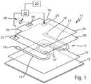
- the heater 11 is shown in an exploded view with an oblique view showing the layer structure. It corresponds to the one from the aforementioned DE 102013200277 A1 ,
- the heating device 11 has a carrier 13, which here consists of metal or stainless steel. It can be flat or flat, alternatively also tubular, as it is from the aforementioned DE 102010043727 A1 is known. On its underside or medium side is to be heated water or flows to be heated Waser over.
- a dielectric insulating layer 15 is provided as the base insulation of the carrier 13, which may consist of glass or glass ceramic. It must be electrically insulated, even at high temperatures. Such a material is known to those skilled in principle for insulation layers.
- a single heating element 17 is applied with meandering course, consisting of individual successively or serially connected heating conductors 17 '. These are largely straight and connected by curved sections. But it could also be provided a single heating element, which is also considerably wider than the narrow heating element 17 'shown here, see also the Fig. 2 ,
- the heating element 17 is formed as a thick-film heating element made of conventional material and applied by conventional methods. At its two ends are enlarged fields as Edelleiteressore 18, which may also be made of other material, such as a usual for thick film heat conductor contact material with significantly better electrical conductivity and especially better contacting properties.
- a dielectric layer 20 is applied over a large area, which may be glass-like or a glass layer.
- an electrode 24 is applied as an electrically conductive pad, in the form of a large-area layer. This is here just as large as the carrier 13 and the insulating layer 15.
- the electrode 24 should not overlap directly on the carrier 13 or the heating element 17, since it must be isolated from the carrier 13 and heating element 17.
- On the electrode 24 may be another cover or insulation layer, but need not. It has two cutouts 25 at the corners, which, together with the underlying windows 21 in the dielectric layer 20, allow a previously described contacting with the heat conductor contacts 18.
- the heating element 17 or its heating conductor 17 'form the other or first connection surface.
- the controller 29 has a memory 29 'on. This is known from the prior art and need not be explained in detail.
- a measuring device 30 is shown, which is connected on the one hand to the electrode 24 via an electrode contact 26 and on the other hand to the heating element 17. As previously explained, the dielectric and resistive properties of the second dielectric layer 20 change with temperature, and the current detected by the measuring device 30 correspondingly increases with increasing temperature. The measuring device then detects this change in the properties of the dielectric layer 20 between heating element 17 and electrode 24.
- Fig. 2 is an embodiment of a heater 111 according to the invention with layer structure to see in a very simplified side view.
- a carrier 112 which may form a container such as a tube, has at the bottom a medium side 113 as a bottom, along which water 5 flows or is present. This water 5 is to be heated by the heater 111.
- a base insulation 115 is provided as an insulating layer.
- a heating element 117 is applied, here as a planar heating element or in thick film technology.
- a dielectric layer 119 is applied, in a different planar configuration, as has been explained above and as shown by the Fig. 3 will be shown.
- an electrode surface 121 is applied as an upper connection surface to the dielectric layer 119 made of electrically conductive material.
- Their areal Design can also be variable.
- the heating element 117 also serves as the lower connection surface to the dielectric layer 119, as has been explained above.
- a controller to the heater 111 are corresponding to the Fig. 1 or the DE 102013200277 A1 a controller, a memory and a measuring device connected, which is not shown here, but is easy to imagine.
- the heater 111 which may be either flat or a tube, so that the Fig. 3 in this case shows the unwound carrier.
- two heating elements are applied, namely a first heating element 117a and a second heating element 117b.
- the heating element 117a forms a partial heating circuit and the heating element 117b forms a partial heating circuit.
- Both heating elements 117a and 117b are interlaced or run meander-shaped into each other, so that they ultimately heat the same surface of the carrier 112 when they are operated individually, in common operation anyway. Thus, so to speak, a different distribution of the heating power of the heater 111 in itself possible.
- both heating elements 117a and 117b are operated in parallel. At minimum desired heating power, the two heating elements 117a and 117b operated in series, possibly also in a kind of emergency operation as previously explained. At an intermediate desired heating power, one of the heating elements 117a and 117b is operated. If they have different power values, the respective power can be generated by the respective individual operation.
- Both heating elements 117a and 117b have the same length and four longitudinal sections. Both heating elements 117a and 117b also have interruptions by contact bridges on two adjacent longitudinal sections in a known manner. This can be reduced locally, the heating power. An electrical contacting of the heating elements 117a and 117b takes place via the individual contact fields 118a and 118b and a common contact field 118 '.
- a plug-in connection 122 which is applied to the contact fields 118 or to the carrier 112, can also be seen schematically, advantageously in accordance with FIG EP 1152639 A2 ,
- a third heating element could for example run separately next to the two heating elements 117a and 117b, or could engage in the central space between the inner heating conductors of the heating element 117a. Under certain circumstances, it could also run along both outer heating conductors of the heating element 117a and would therefore also be virtually interlocked.
- a single planar dielectric layer 119 is applied from a suitable material, shown here by the cross-hatching. It completely covers both heating elements 117a and 117b and extends as far as the edge of the carrier 112 or shortly before.
- an electrode surface 121 is applied to the dielectric layer 119, specifically as a full-area electrode.
- the distinction in terms of area is made by the above-described separate individual operation of the heating elements 117a and 117b.
- the electrode surface 121 is electrically contacted in a manner not shown here, advantageously by means of the plug connection 122.
- the dielectric layer could also be divided into two or correspondingly many partial dielectric layers with a profile corresponding to the underlying heating element. Then, a correspondingly formed partial electrode surface is also applied per partial dielectric layer.
- the production cost would be noticeably higher.
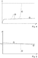
- Fig. 4 is shown schematically how the signal or a leakage current corresponding to the y-axis changes over time.
- the time course is shown here over many hours, for example over 160 hours as operating time.
- the solid curve shown A is a normal operation, the slight increase of the course A comes through a slow, flat calcification on the heater 11 or 111 or on the carrier 13 or 113 on the medium side.
- the dashed lines shown B represents the occurrence of a localized or small scale calcification or an aforementioned hot spot.
- the increase in the course of a few hours, for example, 1 hour to 5 hours to the maximum causes more than a doubling of the signal or leakage current at the maximum.
- the small-scale calcification has flaked off or has come off, which is why in this course B the leakage current or the signal just drops again and then again corresponds to the normal course A.
- the calcification has been completely or incompletely replaced here can not be distinguished on the basis of the waste alone. If the course B then continues parallel to the course A, but with an increased value, it can be assumed that the replacement was not complete. Although this can be recognized, countermeasures are not absolutely necessary.
- the dash-dotted curve C means, similar to the course B, forming a renewed localized or small scale calcification. Therefore, it should run in the rise area similar to the course B. However, the calcification does not dissolve here, a hot spot persists, which is why the leakage current or the signal continues to rise. If it reaches a limit value for the leakage current, in this case the limit value G L , which is, for example, slightly higher than four times the normal leakage current according to the curve A, then this is recognized as dangerous locally limited or small scale calcification with too high a temperature. Then the heat output at the single heating element 17 or at one of the heating elements 117a or 117b is correspondingly greatly reduced or even switched off in order to avoid damage. Via a signaling, not shown, the controller 29 can call an operator for maintenance or for descaling.
- Fig. 5 curves D and E are shown for the Wienleiterstrom I over the time t, again over a time axis of several hours.
- the continuous curve D corresponds to a normal operation, the slight drop of Schwarzleiterstroms represents a slow large scale or complete calcification on the medium side of the carrier 13 or 113 dar.
- a threshold value G H for the Wienleiterstrom is shown in broken lines, which may be, for example, 90% or 80% of the Schuleiterstroms at the beginning, here it is 90%. If this limit value G H is exceeded, the large-scale calcification on the medium side of the carrier 13 or 113 is too strong, consequently a heat loss through the water too low and the risk of overheating of the heater too large. This can therefore also be evaluated as a signal, so that the controller 29 reduces the heating power or the heater 11 or 111 turns off, including appropriate signaling to an operator. In the example shown this may be after about 10 to 20 hours.
- the dash-dotted line E is to show schematically how, at a certain point in time, the heating conductor current drops significantly more rapidly or faster when there is no water for heating and for removing the heat on the medium side of the carrier 13 or 113. This is the above-described case of empty cooking or dry-running in a PTC heating conductor. Then, the threshold value G H falls below quickly, which can be recognized by the controller 29 again. Since the drop of the Schuleiterstroms then but still significantly faster than the course D, just this special case of the reduced Schuleiterstroms can be determined. If at the same time the leakage current increases, for example, similar to the course C accordingly Fig.
- the controller 29 can not evaluate this as a case of a sudden localized or small scale calcification, also not as a case of large-scale calcification, but just as an event of empty cooking or drying. This can then be displayed in a special signaling to an operator. Furthermore, the controller 29 then turns off the heating device 11 or 111 in any case completely, since on the one hand there is otherwise the risk of damage and on the other hand heating makes no sense anyway.
- the heating conductor current falls, for example, within less than one minute, for example within 10 seconds to 30 seconds, so much that it falls below the limit value G H.
- the signal increases accordingly Fig. 4 ,
- the leakage current represented here by a corresponding voltage of the measuring device 30, in the second range behaves when switching on the heater 11 or 111 or the single heating element 17 or the two heating elements 117a and 117b.
- the solid curve is a normal operation, so that it can be seen that after one to two seconds the leakage current reaches a value that appears to be constant per se, with a course essentially corresponding to the curve A of FIG Fig. 4 equivalent.
- Is a hot spot or a localized or small scale calcification given already when switching on the heater 11 or 111 the leakage current increases according to the dashed curve to three times. However, if this calcification or hot spot does not become larger or worse, then a relatively stable state is also achieved, which manifests itself in the substantially constant course.
- the leakage current for the rise takes about 10 seconds, so it is also a very fast process.
- Fig. 7 It is shown how the Schuleiterstrom I behaves over time t (in minutes) when growing a large scale calcification.
- the Schuleiterstrom I is recorded on the left y-axis, on the right y-axis, the power P is recorded.
- the voltage U and the temperature T are recorded, these two without scaling, but with correct relative course.
- the time axis is not scaled in the area to the left of the double-dashed line as in the right, but within the two areas each already linear.
- the temperature T rises rather slowly until it reaches 65 ° C. This is here after about 18 minutes. Since the heating of the heating element due to the heating of the water now drops at a constant water temperature and thus the resulting proportion of change in the resistance of the heating element and thus the Schuleiterstroms I also eliminated, the waste is weaker or less. This is where the large-scale calcification begins. This starts even at a temperature of 65 ° C, well below that of boiling water. As a result of this large-scale calcification, the heating conductor current I drops further, in the example about 6% in 100 hours or 6000 minutes. The heating power drops accordingly, since the voltage U remains clearly identifiable.
Landscapes
- Engineering & Computer Science (AREA)
- Physics & Mathematics (AREA)
- Thermal Sciences (AREA)
- Chemical & Material Sciences (AREA)
- Combustion & Propulsion (AREA)
- Mechanical Engineering (AREA)
- General Engineering & Computer Science (AREA)
- Control Of Resistance Heating (AREA)
- Resistance Heating (AREA)
Claims (13)
- Dispositif de chauffage (111) destiné à chauffer de l'eau (5),- le dispositif de chauffage (111) comportant un support (112),- au moins un élément chauffant (117) étant appliqué sur le support,- l'élément chauffant (117) comportant exactement un conducteur chauffant ou une pluralité de conducteurs chauffants montés en série,- le dispositif de chauffage (111) comportant au moins une couche diélectrique (119) sensiblement bidimensionnelle qui recouvre sensiblement l'au moins un élément chauffant (117),- une surface de raccordement (121) électriquement conductrice étant prévue sur les deux côtés de la couche diélectrique (119),- l'une au moins des surfaces de raccordement (121) étant raccordée à un dispositif de commande ou de mesure destiné à détecter un courant de fuite se présentant sous la forme d'un flux de courant à travers la couche diélectrique (119),
caractérisé en ce que- l'au moins un élément chauffant (117) est relié à des moyens de mesure destinés à surveiller un courant de conducteur de chauffant à travers l'élément chauffant,- au moins deux éléments chauffants (117a, 117b), électriquement séparés et pouvant être commandés indépendamment l'un de l'autre, sont appliqués sur le support (112),- une seule couche diélectrique (119) sensiblement bidimensionnelle est prévue sur un côté des éléments chauffants (117a, 117b) pour le raccordement au dispositif de commande ou de mesure afin de détecter un courant de fuite,- la couche diélectrique (119) recouvre sensiblement les éléments chauffants (117a, 117b). - Dispositif de chauffage selon la revendication 1, caractérisé en ce qu'une couche isolante (115), sur laquelle est appliqué un élément chauffant (117), est appliquée sur le support (112), la couche diélectrique (119) sensiblement bidimensionnelle étant appliquée sur l'élément chauffant et recouvrant en particulier une surface fermée telle que sensiblement un rectangle, une surface de raccordement (121) électriquement conductrice étant appliquée sur la couche diélectrique sur sensiblement la même surface, l'autre surface de raccordement électriquement conductrice étant formée par l'élément chauffant (117).
- Dispositif de chauffage selon la revendication 1 ou 2, caractérisé en ce que la densité de puissance de l'élément chauffant (117) est d'au moins 30 W/cm2, de préférence d'au moins 100 W/cm2.
- Dispositif de chauffage selon l'une des revendications précédentes, caractérisé en ce que les éléments chauffants (117a, 117b) s'engagent les uns dans les autres ou sont disposés de manière entrelacée, de préférence avec des conducteurs chauffants servant de parties des éléments chauffants qui s'étendent de manière rectiligne et parallèlement les uns aux autres, au moins un conducteur chauffant d'un autre élément chauffant (117b) s'étendant entre deux conducteurs chauffants parallèles d'un élément chauffant (117a), en particulier parallèlement à ceux-ci.
- Procédé de fonctionnement d'un dispositif de chauffage (111) selon l'une des revendications précédentes pour chauffer de l'eau (5), caractérisé en ce qu'un courant de conducteur chauffant circulant à travers les éléments chauffants (117a, 117b) ou les conducteurs chauffants et un courant de fuite circulant à travers la couche diélectrique sont surveillés au cours du temps pendant le fonctionnement du dispositif de chauffage,- dans le cas d'un conducteur chauffant CTP, lorsque le courant de conducteur chauffant diminue trop lentement d'au moins 2 % en 100 heures, un entartrage sur une grande surface est détecté du côté milieu du support (112),- dans le cas d'un conducteur chauffant NTC, lorsque le courant de conducteur chauffant augmente trop lentement d'au moins 2 % en 100 heures, un entartrage sur une grande surface est détecté du côté milieu du support (112),- si le courant de fuite augmente trop rapidement d'au moins 30 % en moins de 20 heures, un entartrage localisé ou sur une petite surface ou un point chaud est détecté sur un côté milieu du support (112).
- Procédé selon la revendication 5, caractérisé en ce que la valeur maximale absolue est de 200 % du courant de fuite au début du fonctionnement du dispositif de chauffage (111) sans aucun entartrage du côté milieu du support (112), de préférence de 300 % maximum.
- Procédé selon la revendication 5 ou 6, caractérisé en ce que, après la détection d'un entartrage sur une grande surface du côté milieu du support (112), un opérateur est informé qu'un nettoyage ou un détartrage doit être effectué.
- Procédé selon l'une des revendications 5 à 7, caractérisé en ce que dans le cas où un entartrage localisé ou sur une petite surface du côté milieu du support (112) est détecté, la puissance de chauffage de l'élément chauffant (117a, 117b) dans la zone duquel se produit l'entartrage localisé ou sur petite surface est réduite, cet élément chauffant (117a, 117b) ou le dispositif de chauffage (111) étant en particulier désactivé immédiatement et, après un temps d'attente de 2 secondes à 20 secondes, cet élément chauffant ou le dispositif de chauffage étant réactivé, la désactivation et l'activation de cet élément chauffant ou du dispositif de chauffage étant de préférence répétées plusieurs fois afin d'effectuer un éclatement rapide de l'entartrage local ou sur une petite surface par variation rapide de la température.
- Procédé selon l'une des revendications 5 à 8, caractérisé en ce que, dans le cas où la surveillance du courant de conducteur chauffant ne montre pas une lente diminution ou augmentation et la surveillance du courant de fuite à travers la couche diélectrique (119) ne montre pas une forte augmentation rapide, mais à un instant déterminé une diminution ou une augmentation rapide du courant de conducteur chauffant ainsi qu'une forte augmentation rapide du courant de fuite se produisent en même temps, cela est évalué comme une cuisson à vide d'un récipient pourvu du dispositif de chauffage (111).
- Procédé selon l'une des revendications 5 à 9, caractérisé en ce que, lors du franchissement vers le bas d'une valeur limite du courant de fuite et/ou lors d'une trop forte augmentation du courant de fuite, une recherche d'erreur est démarrée et les éléments chauffants (117a, 117b) sont pour cela activés individuellement les uns après les autres et, dans chaque cas, le courant de fuite est détecté au niveau de l'au moins une couche diélectrique (119) au-dessus des éléments chauffants activés,- dans le cas où le courant de fuite, lors de l'activation individuelle des éléments chauffants (117a, 117b), est le même, en particulier est différent de 10 % maximum, un entartrage sur une grande surface est détecté du côté milieu du support (112),- dans le cas où le courant de fuite, lors de l'activation individuelle des éléments chauffants (117a, 117b), est différent d'au moins 10 %, en particulier d'au moins 30 %, un entartrage localement limité ou sur une petite surface est détecté sur le côté moyen du support (112) dans la région de l'élément chauffant avec un courant de fuite plus élevé.
- Procédé selon la revendication 10, caractérisé en ce que, dans le cas où le courant de fuite, lors de l'activation individuelle des éléments chauffants (117a, 117b), est le même et montre une forte augmentation rapide et à peu près la même, notamment d'au moins 20 % en moins d'une minute, cela est détecté comme une cuisson à vide d'un récipient pourvu de l'élément chauffant (111).
- Procédé selon la revendication 10 ou 11, caractérisé en ce que, dans le cas où un entartrage localisé ou sur une petite surface est détecté du côté milieu du support (112) dans la région d'un élément chauffant (117a, 117b), cet élément chauffant est réduit en termes de puissance ou désactivé et au moins un autre élément chauffant est activé avec une puissance inchangée ; dans un autre cas où un entartrage sur une grande surface est détecté du côté milieu du support, cet élément chauffant est monté en série avec au moins un autre élément chauffant afin de continuer à fonctionner avec une puissance réduite.
- Procédé selon l'une des revendications 5 à 12 dans un lave-vaisselle, un dispositif de commande du lave-vaisselle diminuant un réglage de l'adoucissement d'eau dans le lave-vaisselle afin de réduire l'adoucissement de l'eau en vue d'un détartrage plus faible de l'eau jusqu'à détecter de préférence un entartrage sur une grande surface du côté milieu du support (112) lors d'une plus lente diminution ou une plus lente augmentation du courant de conducteur chauffant, le dispositif de commande augmentant ou renforçant encore, en réponse, automatiquement l'adoucissement de l'eau.
Priority Applications (1)
| Application Number | Priority Date | Filing Date | Title |
|---|---|---|---|
| PL16188807T PL3145273T3 (pl) | 2015-09-21 | 2016-09-14 | Urządzenie grzewcze do ogrzewania wody i sposób działania takiego urządzenia grzewczego |
Applications Claiming Priority (2)
| Application Number | Priority Date | Filing Date | Title |
|---|---|---|---|
| DE102015218121.9A DE102015218121A1 (de) | 2015-09-21 | 2015-09-21 | Heizeinrichtung zum Erhitzen von Wasser und Verfahren zum Betrieb einer solchen Heizeinrichtung |
| DE102015218120.0A DE102015218120B4 (de) | 2015-09-21 | 2015-09-21 | Verfahren zum Betrieb einer Heizeinrichtung zum Erhitzen von Wasser , Heizeinrichtung und Geschirrspülmaschine |
Publications (2)
| Publication Number | Publication Date |
|---|---|
| EP3145273A1 EP3145273A1 (fr) | 2017-03-22 |
| EP3145273B1 true EP3145273B1 (fr) | 2019-08-07 |
Family
ID=56939888
Family Applications (1)
| Application Number | Title | Priority Date | Filing Date |
|---|---|---|---|
| EP16188807.8A Active EP3145273B1 (fr) | 2015-09-21 | 2016-09-14 | Dispositif de chauffage d'eau et procede de fonctionnement d'un tel dispositif de chauffage |
Country Status (5)
| Country | Link |
|---|---|
| US (1) | US20170086257A1 (fr) |
| EP (1) | EP3145273B1 (fr) |
| CN (1) | CN106993995A (fr) |
| ES (1) | ES2751548T3 (fr) |
| PL (1) | PL3145273T3 (fr) |
Cited By (1)
| Publication number | Priority date | Publication date | Assignee | Title |
|---|---|---|---|---|
| DE102020207784A1 (de) | 2020-06-23 | 2021-12-23 | E.G.O. Elektro-Gerätebau GmbH | Heizeinrichtung mit einer Temperaturmesseinrichtung und Verfahren zur Temperaturmessung an der Heizeinrichtung und zur Herstellung |
Families Citing this family (13)
| Publication number | Priority date | Publication date | Assignee | Title |
|---|---|---|---|---|
| DE102016224069A1 (de) * | 2016-12-02 | 2018-06-07 | E.G.O. Elektro-Gerätebau GmbH | Kochgerät mit einer Kochplatte und einer Heizeinrichtung darunter |
| JP2020029961A (ja) * | 2016-12-14 | 2020-02-27 | 株式会社デンソー | 流体加熱装置の検査方法、および流体加熱装置の製造方法 |
| DE102017211123A1 (de) * | 2017-06-30 | 2019-01-03 | E.G.O. Elektro-Gerätebau GmbH | Verfahren zum Bearbeiten eines elektrischen Bauteils mit Schichtaufbau |
| CN108414861B (zh) * | 2018-03-07 | 2020-10-02 | 宁波弘讯科技股份有限公司 | 电热故障自检方法、装置、系统及计算机可读存储介质 |
| DE102018213869B4 (de) * | 2018-08-17 | 2020-03-05 | E.G.O. Elektro-Gerätebau GmbH | Heizeinrichtung und Verfahren zum Betrieb einer Heizeinrichtung |
| DE102018217239B4 (de) * | 2018-10-09 | 2020-06-18 | E.G.O. Elektro-Gerätebau GmbH | Heizvorrichtung und Verfahren zur Temperaturerfassung an einer Heizvorrichtung |
| US11044789B2 (en) | 2018-10-11 | 2021-06-22 | Goodrich Corporation | Three dimensionally printed heated positive temperature coefficient tubes |
| CN109973972B (zh) * | 2019-04-08 | 2024-06-18 | 广东美的暖通设备有限公司 | 蒸汽发生装置、控制方法及空气调节装置 |
| US11614497B2 (en) * | 2019-12-03 | 2023-03-28 | International Business Machines Corporation | Leakage characterization for electronic circuit temperature monitoring |
| EP3835654B1 (fr) | 2019-12-13 | 2024-10-09 | E.G.O. Elektro-Gerätebau GmbH | Procédé de fonctionnement d'un générateur de vapeur, générateur de vapeur et appareil de cuisson |
| PL3840528T3 (pl) | 2019-12-16 | 2023-02-20 | E.G.O. Elektro-Gerätebau GmbH | Sposób działania wytwornicy pary, wytwornica pary i urządzenie do gotowania z wytwornicą pary |
| WO2021170232A1 (fr) | 2020-02-26 | 2021-09-02 | E.G.O. Elektro-Gerätebau GmbH | Dispositif de chauffage |
| EP3901466B1 (fr) | 2020-04-24 | 2023-10-25 | E.G.O. Elektro-Gerätebau GmbH | Procédé de fonctionnement d'une pompe |
Family Cites Families (9)
| Publication number | Priority date | Publication date | Assignee | Title |
|---|---|---|---|---|
| GB2351894B (en) * | 1999-05-04 | 2003-10-15 | Otter Controls Ltd | Improvements relating to heating elements |
| DE10021512A1 (de) | 2000-05-03 | 2001-11-08 | Ego Elektro Geraetebau Gmbh | Elektrische Heizeinheit, insbesondere für flüssige Medien |
| US20020192075A1 (en) * | 2001-06-13 | 2002-12-19 | Volker Block | Fan |
| US8890038B2 (en) * | 2004-03-30 | 2014-11-18 | Thermoceramix Inc. | Heating apparatus with multiple element array |
| NL2000081C2 (nl) * | 2006-05-23 | 2007-11-26 | Ferro Techniek Holding Bv | Elektrische verwarmingsinrichting met temperatuurdetectie door dielektrische laag. |
| NL2001806C2 (en) * | 2008-07-15 | 2010-01-18 | Otter Controls Ltd | Heating element and method for operating such a heating element. |
| DE102010043727A1 (de) | 2010-11-10 | 2012-05-10 | E.G.O. Elektro-Gerätebau GmbH | Pumpe |
| DE102012213385A1 (de) * | 2012-07-30 | 2014-05-22 | E.G.O. Elektro-Gerätebau GmbH | Heizeinrichtung und Elektrogerät mit Heizeinrichtung |
| DE102013200277A1 (de) | 2013-01-10 | 2014-01-30 | E.G.O. Elektro-Gerätebau GmbH | Heizeinrichtung und Verfahren zur Temperaturmessung an der Heizeinrichtung |
-
2016
- 2016-09-14 EP EP16188807.8A patent/EP3145273B1/fr active Active
- 2016-09-14 PL PL16188807T patent/PL3145273T3/pl unknown
- 2016-09-14 ES ES16188807T patent/ES2751548T3/es active Active
- 2016-09-19 US US15/268,926 patent/US20170086257A1/en not_active Abandoned
- 2016-09-21 CN CN201610836727.2A patent/CN106993995A/zh active Pending
Non-Patent Citations (1)
| Title |
|---|
| None * |
Cited By (2)
| Publication number | Priority date | Publication date | Assignee | Title |
|---|---|---|---|---|
| DE102020207784A1 (de) | 2020-06-23 | 2021-12-23 | E.G.O. Elektro-Gerätebau GmbH | Heizeinrichtung mit einer Temperaturmesseinrichtung und Verfahren zur Temperaturmessung an der Heizeinrichtung und zur Herstellung |
| EP3930421A1 (fr) | 2020-06-23 | 2021-12-29 | E.G.O. Elektro-Gerätebau GmbH | Dispositif de chauffage doté d'un dispositif de mesure de la température et procédé de mesure de la température sur le dispositif de chauffage et de fabrication |
Also Published As
| Publication number | Publication date |
|---|---|
| CN106993995A (zh) | 2017-08-01 |
| ES2751548T3 (es) | 2020-04-01 |
| PL3145273T3 (pl) | 2020-03-31 |
| US20170086257A1 (en) | 2017-03-23 |
| EP3145273A1 (fr) | 2017-03-22 |
Similar Documents
| Publication | Publication Date | Title |
|---|---|---|
| EP3145273B1 (fr) | Dispositif de chauffage d'eau et procede de fonctionnement d'un tel dispositif de chauffage | |
| EP3088800B1 (fr) | Dispositif de chauffage de liquides, evaporateur pour un appareil de cuisson electrique et procede de fonctionnement d'un dispositif de chauffage | |
| EP3096585B1 (fr) | Dispositif de chauffage destiné à chauffer des fluides et procédé de fonctionnement d'un tel dispositif de chauffage | |
| EP3278691B1 (fr) | Évaporateur et appareil de cuisson comprenant un tel dispositif | |
| EP2693835B1 (fr) | Dispositif de chauffage et appareil électrique doté d'un dispositif de chauffage | |
| EP3250003A1 (fr) | Dispositif de chauffage | |
| EP1152639B1 (fr) | Unité de chauffage électrique, particulièrement destiné à des milieux liquides | |
| EP0471171A2 (fr) | Dispositif pour la régulation et le limitation de la puissance d'une surface de chauffage en céramique ou un matériau similaire | |
| EP3197241B1 (fr) | Dispositif de chauffage et procede de mesure des temperatures sur un dispositif de chauffage | |
| EP2840404B1 (fr) | Chauffe-eau électrique instantané à fil nu et procédé de commande de celui-ci | |
| EP3614797B1 (fr) | Dispositif de chauffage et procédé de fonctionnement d'un dispositif de chauffage | |
| EP3637948B1 (fr) | Dispositif de chauffage et procédé d'enregistrement de température sur un dispositif de chauffage | |
| DE102015218121A1 (de) | Heizeinrichtung zum Erhitzen von Wasser und Verfahren zum Betrieb einer solchen Heizeinrichtung | |
| EP2183943A1 (fr) | Dispositif de chauffage, procédé pour faire fonctionner un dispositif de chauffage et appareil de chauffage électrique appartenant à un tel dispositif de chauffage | |
| WO2014001302A1 (fr) | Chauffe-eau et procédé permettant de faire fonctionner un chauffe-eau | |
| DE102015218120B4 (de) | Verfahren zum Betrieb einer Heizeinrichtung zum Erhitzen von Wasser , Heizeinrichtung und Geschirrspülmaschine | |
| EP3799527A1 (fr) | Plaque de cuisson à induction et procédé de commande d'une plaque de cuisson à induction | |
| EP3136822B1 (fr) | Procede de determination de temperature | |
| DE19934319A1 (de) | Heizvorrichtung mit Laugentemperaturregelung | |
| DE102018203609B4 (de) | Verfahren und Vorrichtung zur Erfassung einer Temperatur an einem Heizelement | |
| DE102007056917A1 (de) | Verfahren zum Fertigungstoleranzausgleich von elektrischen Verbrauchern | |
| DE102015205496A1 (de) | Erhitzen von Flüssigkeit in einem Haushaltsgerät | |
| DE102019219604A1 (de) | Verfahren zum Betrieb einer Verdampfereinrichtung, Verdampfereinrichtung und Dampfgarer | |
| DE10110791C1 (de) | Keramisches Kochsystem mit Glaskeramikplatte, Isolationsschicht und Heizelement | |
| EP2001267B1 (fr) | Procédé destiné à la commande d'un champ de cuisson et dispositif d'exécution du procédé |
Legal Events
| Date | Code | Title | Description |
|---|---|---|---|
| PUAI | Public reference made under article 153(3) epc to a published international application that has entered the european phase |
Free format text: ORIGINAL CODE: 0009012 |
|
| STAA | Information on the status of an ep patent application or granted ep patent |
Free format text: STATUS: THE APPLICATION HAS BEEN PUBLISHED |
|
| AK | Designated contracting states |
Kind code of ref document: A1 Designated state(s): AL AT BE BG CH CY CZ DE DK EE ES FI FR GB GR HR HU IE IS IT LI LT LU LV MC MK MT NL NO PL PT RO RS SE SI SK SM TR |
|
| AX | Request for extension of the european patent |
Extension state: BA ME |
|
| STAA | Information on the status of an ep patent application or granted ep patent |
Free format text: STATUS: REQUEST FOR EXAMINATION WAS MADE |
|
| 17P | Request for examination filed |
Effective date: 20170921 |
|
| RBV | Designated contracting states (corrected) |
Designated state(s): AL AT BE BG CH CY CZ DE DK EE ES FI FR GB GR HR HU IE IS IT LI LT LU LV MC MK MT NL NO PL PT RO RS SE SI SK SM TR |
|
| GRAP | Despatch of communication of intention to grant a patent |
Free format text: ORIGINAL CODE: EPIDOSNIGR1 |
|
| STAA | Information on the status of an ep patent application or granted ep patent |
Free format text: STATUS: GRANT OF PATENT IS INTENDED |
|
| INTG | Intention to grant announced |
Effective date: 20190225 |
|
| GRAS | Grant fee paid |
Free format text: ORIGINAL CODE: EPIDOSNIGR3 |
|
| GRAA | (expected) grant |
Free format text: ORIGINAL CODE: 0009210 |
|
| STAA | Information on the status of an ep patent application or granted ep patent |
Free format text: STATUS: THE PATENT HAS BEEN GRANTED |
|
| AK | Designated contracting states |
Kind code of ref document: B1 Designated state(s): AL AT BE BG CH CY CZ DE DK EE ES FI FR GB GR HR HU IE IS IT LI LT LU LV MC MK MT NL NO PL PT RO RS SE SI SK SM TR |
|
| REG | Reference to a national code |
Ref country code: GB Ref legal event code: FG4D Free format text: NOT ENGLISH |
|
| REG | Reference to a national code |
Ref country code: CH Ref legal event code: EP Ref country code: AT Ref legal event code: REF Ref document number: 1165859 Country of ref document: AT Kind code of ref document: T Effective date: 20190815 |
|
| REG | Reference to a national code |
Ref country code: DE Ref legal event code: R096 Ref document number: 502016005902 Country of ref document: DE |
|
| REG | Reference to a national code |
Ref country code: IE Ref legal event code: FG4D Free format text: LANGUAGE OF EP DOCUMENT: GERMAN |
|
| REG | Reference to a national code |
Ref country code: NL Ref legal event code: MP Effective date: 20190807 |
|
| REG | Reference to a national code |
Ref country code: LT Ref legal event code: MG4D |
|
| PG25 | Lapsed in a contracting state [announced via postgrant information from national office to epo] |
Ref country code: BG Free format text: LAPSE BECAUSE OF FAILURE TO SUBMIT A TRANSLATION OF THE DESCRIPTION OR TO PAY THE FEE WITHIN THE PRESCRIBED TIME-LIMIT Effective date: 20191107 Ref country code: SE Free format text: LAPSE BECAUSE OF FAILURE TO SUBMIT A TRANSLATION OF THE DESCRIPTION OR TO PAY THE FEE WITHIN THE PRESCRIBED TIME-LIMIT Effective date: 20190807 Ref country code: NL Free format text: LAPSE BECAUSE OF FAILURE TO SUBMIT A TRANSLATION OF THE DESCRIPTION OR TO PAY THE FEE WITHIN THE PRESCRIBED TIME-LIMIT Effective date: 20190807 Ref country code: NO Free format text: LAPSE BECAUSE OF FAILURE TO SUBMIT A TRANSLATION OF THE DESCRIPTION OR TO PAY THE FEE WITHIN THE PRESCRIBED TIME-LIMIT Effective date: 20191107 Ref country code: LT Free format text: LAPSE BECAUSE OF FAILURE TO SUBMIT A TRANSLATION OF THE DESCRIPTION OR TO PAY THE FEE WITHIN THE PRESCRIBED TIME-LIMIT Effective date: 20190807 Ref country code: FI Free format text: LAPSE BECAUSE OF FAILURE TO SUBMIT A TRANSLATION OF THE DESCRIPTION OR TO PAY THE FEE WITHIN THE PRESCRIBED TIME-LIMIT Effective date: 20190807 Ref country code: PT Free format text: LAPSE BECAUSE OF FAILURE TO SUBMIT A TRANSLATION OF THE DESCRIPTION OR TO PAY THE FEE WITHIN THE PRESCRIBED TIME-LIMIT Effective date: 20191209 Ref country code: HR Free format text: LAPSE BECAUSE OF FAILURE TO SUBMIT A TRANSLATION OF THE DESCRIPTION OR TO PAY THE FEE WITHIN THE PRESCRIBED TIME-LIMIT Effective date: 20190807 |
|
| PG25 | Lapsed in a contracting state [announced via postgrant information from national office to epo] |
Ref country code: GR Free format text: LAPSE BECAUSE OF FAILURE TO SUBMIT A TRANSLATION OF THE DESCRIPTION OR TO PAY THE FEE WITHIN THE PRESCRIBED TIME-LIMIT Effective date: 20191108 Ref country code: AL Free format text: LAPSE BECAUSE OF FAILURE TO SUBMIT A TRANSLATION OF THE DESCRIPTION OR TO PAY THE FEE WITHIN THE PRESCRIBED TIME-LIMIT Effective date: 20190807 Ref country code: LV Free format text: LAPSE BECAUSE OF FAILURE TO SUBMIT A TRANSLATION OF THE DESCRIPTION OR TO PAY THE FEE WITHIN THE PRESCRIBED TIME-LIMIT Effective date: 20190807 Ref country code: RS Free format text: LAPSE BECAUSE OF FAILURE TO SUBMIT A TRANSLATION OF THE DESCRIPTION OR TO PAY THE FEE WITHIN THE PRESCRIBED TIME-LIMIT Effective date: 20190807 Ref country code: IS Free format text: LAPSE BECAUSE OF FAILURE TO SUBMIT A TRANSLATION OF THE DESCRIPTION OR TO PAY THE FEE WITHIN THE PRESCRIBED TIME-LIMIT Effective date: 20191207 |
|
| REG | Reference to a national code |
Ref country code: ES Ref legal event code: FG2A Ref document number: 2751548 Country of ref document: ES Kind code of ref document: T3 Effective date: 20200401 |
|
| PG25 | Lapsed in a contracting state [announced via postgrant information from national office to epo] |
Ref country code: DK Free format text: LAPSE BECAUSE OF FAILURE TO SUBMIT A TRANSLATION OF THE DESCRIPTION OR TO PAY THE FEE WITHIN THE PRESCRIBED TIME-LIMIT Effective date: 20190807 Ref country code: EE Free format text: LAPSE BECAUSE OF FAILURE TO SUBMIT A TRANSLATION OF THE DESCRIPTION OR TO PAY THE FEE WITHIN THE PRESCRIBED TIME-LIMIT Effective date: 20190807 Ref country code: RO Free format text: LAPSE BECAUSE OF FAILURE TO SUBMIT A TRANSLATION OF THE DESCRIPTION OR TO PAY THE FEE WITHIN THE PRESCRIBED TIME-LIMIT Effective date: 20190807 |
|
| PG25 | Lapsed in a contracting state [announced via postgrant information from national office to epo] |
Ref country code: MC Free format text: LAPSE BECAUSE OF FAILURE TO SUBMIT A TRANSLATION OF THE DESCRIPTION OR TO PAY THE FEE WITHIN THE PRESCRIBED TIME-LIMIT Effective date: 20190807 Ref country code: CZ Free format text: LAPSE BECAUSE OF FAILURE TO SUBMIT A TRANSLATION OF THE DESCRIPTION OR TO PAY THE FEE WITHIN THE PRESCRIBED TIME-LIMIT Effective date: 20190807 Ref country code: SK Free format text: LAPSE BECAUSE OF FAILURE TO SUBMIT A TRANSLATION OF THE DESCRIPTION OR TO PAY THE FEE WITHIN THE PRESCRIBED TIME-LIMIT Effective date: 20190807 Ref country code: IS Free format text: LAPSE BECAUSE OF FAILURE TO SUBMIT A TRANSLATION OF THE DESCRIPTION OR TO PAY THE FEE WITHIN THE PRESCRIBED TIME-LIMIT Effective date: 20200224 Ref country code: SM Free format text: LAPSE BECAUSE OF FAILURE TO SUBMIT A TRANSLATION OF THE DESCRIPTION OR TO PAY THE FEE WITHIN THE PRESCRIBED TIME-LIMIT Effective date: 20190807 |
|
| REG | Reference to a national code |
Ref country code: CH Ref legal event code: PL |
|
| REG | Reference to a national code |
Ref country code: DE Ref legal event code: R097 Ref document number: 502016005902 Country of ref document: DE |
|
| PLBE | No opposition filed within time limit |
Free format text: ORIGINAL CODE: 0009261 |
|
| STAA | Information on the status of an ep patent application or granted ep patent |
Free format text: STATUS: NO OPPOSITION FILED WITHIN TIME LIMIT |
|
| PG2D | Information on lapse in contracting state deleted |
Ref country code: IS |
|
| PG25 | Lapsed in a contracting state [announced via postgrant information from national office to epo] |
Ref country code: CH Free format text: LAPSE BECAUSE OF NON-PAYMENT OF DUE FEES Effective date: 20190930 Ref country code: LI Free format text: LAPSE BECAUSE OF NON-PAYMENT OF DUE FEES Effective date: 20190930 Ref country code: LU Free format text: LAPSE BECAUSE OF NON-PAYMENT OF DUE FEES Effective date: 20190914 Ref country code: IE Free format text: LAPSE BECAUSE OF NON-PAYMENT OF DUE FEES Effective date: 20190914 |
|
| REG | Reference to a national code |
Ref country code: BE Ref legal event code: MM Effective date: 20190930 |
|
| 26N | No opposition filed |
Effective date: 20200603 |
|
| PG25 | Lapsed in a contracting state [announced via postgrant information from national office to epo] |
Ref country code: SI Free format text: LAPSE BECAUSE OF FAILURE TO SUBMIT A TRANSLATION OF THE DESCRIPTION OR TO PAY THE FEE WITHIN THE PRESCRIBED TIME-LIMIT Effective date: 20190807 Ref country code: BE Free format text: LAPSE BECAUSE OF NON-PAYMENT OF DUE FEES Effective date: 20190930 |
|
| PG25 | Lapsed in a contracting state [announced via postgrant information from national office to epo] |
Ref country code: CY Free format text: LAPSE BECAUSE OF FAILURE TO SUBMIT A TRANSLATION OF THE DESCRIPTION OR TO PAY THE FEE WITHIN THE PRESCRIBED TIME-LIMIT Effective date: 20190807 |
|
| PG25 | Lapsed in a contracting state [announced via postgrant information from national office to epo] |
Ref country code: HU Free format text: LAPSE BECAUSE OF FAILURE TO SUBMIT A TRANSLATION OF THE DESCRIPTION OR TO PAY THE FEE WITHIN THE PRESCRIBED TIME-LIMIT; INVALID AB INITIO Effective date: 20160914 Ref country code: MT Free format text: LAPSE BECAUSE OF FAILURE TO SUBMIT A TRANSLATION OF THE DESCRIPTION OR TO PAY THE FEE WITHIN THE PRESCRIBED TIME-LIMIT Effective date: 20190807 |
|
| PG25 | Lapsed in a contracting state [announced via postgrant information from national office to epo] |
Ref country code: MK Free format text: LAPSE BECAUSE OF FAILURE TO SUBMIT A TRANSLATION OF THE DESCRIPTION OR TO PAY THE FEE WITHIN THE PRESCRIBED TIME-LIMIT Effective date: 20190807 |
|
| REG | Reference to a national code |
Ref country code: AT Ref legal event code: MM01 Ref document number: 1165859 Country of ref document: AT Kind code of ref document: T Effective date: 20210914 |
|
| PG25 | Lapsed in a contracting state [announced via postgrant information from national office to epo] |
Ref country code: AT Free format text: LAPSE BECAUSE OF NON-PAYMENT OF DUE FEES Effective date: 20210914 |
|
| PGFP | Annual fee paid to national office [announced via postgrant information from national office to epo] |
Ref country code: TR Payment date: 20230906 Year of fee payment: 8 |
|
| PGFP | Annual fee paid to national office [announced via postgrant information from national office to epo] |
Ref country code: PL Payment date: 20230811 Year of fee payment: 8 |
|
| PGFP | Annual fee paid to national office [announced via postgrant information from national office to epo] |
Ref country code: ES Payment date: 20231019 Year of fee payment: 8 |
|
| PGFP | Annual fee paid to national office [announced via postgrant information from national office to epo] |
Ref country code: IT Payment date: 20230929 Year of fee payment: 8 |
|
| PGFP | Annual fee paid to national office [announced via postgrant information from national office to epo] |
Ref country code: DE Payment date: 20240919 Year of fee payment: 9 |
|
| PGFP | Annual fee paid to national office [announced via postgrant information from national office to epo] |
Ref country code: GB Payment date: 20240923 Year of fee payment: 9 |
|
| PGFP | Annual fee paid to national office [announced via postgrant information from national office to epo] |
Ref country code: FR Payment date: 20240930 Year of fee payment: 9 |