CN110836532B - Heating device and method for operating a heating device - Google Patents
Heating device and method for operating a heating device Download PDFInfo
- Publication number
- CN110836532B CN110836532B CN201910763938.1A CN201910763938A CN110836532B CN 110836532 B CN110836532 B CN 110836532B CN 201910763938 A CN201910763938 A CN 201910763938A CN 110836532 B CN110836532 B CN 110836532B
- Authority
- CN
- China
- Prior art keywords
- heating device
- heating
- fluid chamber
- fluid
- supply voltage
- Prior art date
- Legal status (The legal status is an assumption and is not a legal conclusion. Google has not performed a legal analysis and makes no representation as to the accuracy of the status listed.)
- Active
Links
- 238000010438 heat treatment Methods 0.000 title claims abstract description 201
- 238000000034 method Methods 0.000 title claims abstract description 19
- 239000012530 fluid Substances 0.000 claims abstract description 85
- 238000009413 insulation Methods 0.000 claims abstract description 20
- 230000001419 dependent effect Effects 0.000 claims abstract description 14
- XLYOFNOQVPJJNP-UHFFFAOYSA-N water Substances O XLYOFNOQVPJJNP-UHFFFAOYSA-N 0.000 claims description 32
- 239000004020 conductor Substances 0.000 claims description 19
- 230000002308 calcification Effects 0.000 claims description 11
- 238000005086 pumping Methods 0.000 claims description 5
- 208000004434 Calcinosis Diseases 0.000 description 10
- 238000013021 overheating Methods 0.000 description 8
- 238000001514 detection method Methods 0.000 description 6
- 239000000463 material Substances 0.000 description 5
- 230000006378 damage Effects 0.000 description 3
- 230000000694 effects Effects 0.000 description 3
- 230000008020 evaporation Effects 0.000 description 3
- 238000001704 evaporation Methods 0.000 description 3
- 230000008569 process Effects 0.000 description 3
- 230000008859 change Effects 0.000 description 2
- 238000010586 diagram Methods 0.000 description 2
- 239000011521 glass Substances 0.000 description 2
- 230000007774 longterm Effects 0.000 description 2
- 239000002184 metal Substances 0.000 description 2
- 238000012544 monitoring process Methods 0.000 description 2
- 230000007704 transition Effects 0.000 description 2
- 238000007796 conventional method Methods 0.000 description 1
- 230000000254 damaging effect Effects 0.000 description 1
- 230000001066 destructive effect Effects 0.000 description 1
- 230000010259 detection of temperature stimulus Effects 0.000 description 1
- 238000005516 engineering process Methods 0.000 description 1
- 230000007613 environmental effect Effects 0.000 description 1
- 239000002241 glass-ceramic Substances 0.000 description 1
- 238000007689 inspection Methods 0.000 description 1
- 239000007788 liquid Substances 0.000 description 1
- 230000007257 malfunction Effects 0.000 description 1
- 238000012545 processing Methods 0.000 description 1
- 230000009467 reduction Effects 0.000 description 1
- 230000004044 response Effects 0.000 description 1
- 229910001220 stainless steel Inorganic materials 0.000 description 1
- 239000010935 stainless steel Substances 0.000 description 1
- 238000012546 transfer Methods 0.000 description 1
- 230000001052 transient effect Effects 0.000 description 1
Images


Classifications
-
- H—ELECTRICITY
- H05—ELECTRIC TECHNIQUES NOT OTHERWISE PROVIDED FOR
- H05B—ELECTRIC HEATING; ELECTRIC LIGHT SOURCES NOT OTHERWISE PROVIDED FOR; CIRCUIT ARRANGEMENTS FOR ELECTRIC LIGHT SOURCES, IN GENERAL
- H05B3/00—Ohmic-resistance heating
- H05B3/40—Heating elements having the shape of rods or tubes
- H05B3/42—Heating elements having the shape of rods or tubes non-flexible
-
- F—MECHANICAL ENGINEERING; LIGHTING; HEATING; WEAPONS; BLASTING
- F24—HEATING; RANGES; VENTILATING
- F24H—FLUID HEATERS, e.g. WATER OR AIR HEATERS, HAVING HEAT-GENERATING MEANS, e.g. HEAT PUMPS, IN GENERAL
- F24H9/00—Details
- F24H9/20—Arrangement or mounting of control or safety devices
- F24H9/2007—Arrangement or mounting of control or safety devices for water heaters
- F24H9/2014—Arrangement or mounting of control or safety devices for water heaters using electrical energy supply
- F24H9/2021—Storage heaters
-
- H—ELECTRICITY
- H05—ELECTRIC TECHNIQUES NOT OTHERWISE PROVIDED FOR
- H05B—ELECTRIC HEATING; ELECTRIC LIGHT SOURCES NOT OTHERWISE PROVIDED FOR; CIRCUIT ARRANGEMENTS FOR ELECTRIC LIGHT SOURCES, IN GENERAL
- H05B3/00—Ohmic-resistance heating
- H05B3/20—Heating elements having extended surface area substantially in a two-dimensional plane, e.g. plate-heater
- H05B3/22—Heating elements having extended surface area substantially in a two-dimensional plane, e.g. plate-heater non-flexible
- H05B3/26—Heating elements having extended surface area substantially in a two-dimensional plane, e.g. plate-heater non-flexible heating conductor mounted on insulating base
-
- F—MECHANICAL ENGINEERING; LIGHTING; HEATING; WEAPONS; BLASTING
- F22—STEAM GENERATION
- F22B—METHODS OF STEAM GENERATION; STEAM BOILERS
- F22B1/00—Methods of steam generation characterised by form of heating method
- F22B1/28—Methods of steam generation characterised by form of heating method in boilers heated electrically
- F22B1/284—Methods of steam generation characterised by form of heating method in boilers heated electrically with water in reservoirs
-
- F—MECHANICAL ENGINEERING; LIGHTING; HEATING; WEAPONS; BLASTING
- F24—HEATING; RANGES; VENTILATING
- F24H—FLUID HEATERS, e.g. WATER OR AIR HEATERS, HAVING HEAT-GENERATING MEANS, e.g. HEAT PUMPS, IN GENERAL
- F24H1/00—Water heaters, e.g. boilers, continuous-flow heaters or water-storage heaters
- F24H1/18—Water-storage heaters
- F24H1/185—Water-storage heaters using electric energy supply
-
- F—MECHANICAL ENGINEERING; LIGHTING; HEATING; WEAPONS; BLASTING
- F24—HEATING; RANGES; VENTILATING
- F24H—FLUID HEATERS, e.g. WATER OR AIR HEATERS, HAVING HEAT-GENERATING MEANS, e.g. HEAT PUMPS, IN GENERAL
- F24H1/00—Water heaters, e.g. boilers, continuous-flow heaters or water-storage heaters
- F24H1/18—Water-storage heaters
- F24H1/20—Water-storage heaters with immersed heating elements, e.g. electric elements or furnace tubes
- F24H1/201—Water-storage heaters with immersed heating elements, e.g. electric elements or furnace tubes using electric energy supply
- F24H1/202—Water-storage heaters with immersed heating elements, e.g. electric elements or furnace tubes using electric energy supply with resistances
-
- F—MECHANICAL ENGINEERING; LIGHTING; HEATING; WEAPONS; BLASTING
- F24—HEATING; RANGES; VENTILATING
- F24H—FLUID HEATERS, e.g. WATER OR AIR HEATERS, HAVING HEAT-GENERATING MEANS, e.g. HEAT PUMPS, IN GENERAL
- F24H15/00—Control of fluid heaters
- F24H15/10—Control of fluid heaters characterised by the purpose of the control
- F24H15/124—Preventing or detecting electric faults, e.g. electric leakage
-
- F—MECHANICAL ENGINEERING; LIGHTING; HEATING; WEAPONS; BLASTING
- F24—HEATING; RANGES; VENTILATING
- F24H—FLUID HEATERS, e.g. WATER OR AIR HEATERS, HAVING HEAT-GENERATING MEANS, e.g. HEAT PUMPS, IN GENERAL
- F24H15/00—Control of fluid heaters
- F24H15/10—Control of fluid heaters characterised by the purpose of the control
- F24H15/128—Preventing overheating
-
- F—MECHANICAL ENGINEERING; LIGHTING; HEATING; WEAPONS; BLASTING
- F24—HEATING; RANGES; VENTILATING
- F24H—FLUID HEATERS, e.g. WATER OR AIR HEATERS, HAVING HEAT-GENERATING MEANS, e.g. HEAT PUMPS, IN GENERAL
- F24H15/00—Control of fluid heaters
- F24H15/10—Control of fluid heaters characterised by the purpose of the control
- F24H15/14—Cleaning; Sterilising; Preventing contamination by bacteria or microorganisms, e.g. by replacing fluid in tanks or conduits
-
- F—MECHANICAL ENGINEERING; LIGHTING; HEATING; WEAPONS; BLASTING
- F24—HEATING; RANGES; VENTILATING
- F24H—FLUID HEATERS, e.g. WATER OR AIR HEATERS, HAVING HEAT-GENERATING MEANS, e.g. HEAT PUMPS, IN GENERAL
- F24H15/00—Control of fluid heaters
- F24H15/20—Control of fluid heaters characterised by control inputs
-
- F—MECHANICAL ENGINEERING; LIGHTING; HEATING; WEAPONS; BLASTING
- F24—HEATING; RANGES; VENTILATING
- F24H—FLUID HEATERS, e.g. WATER OR AIR HEATERS, HAVING HEAT-GENERATING MEANS, e.g. HEAT PUMPS, IN GENERAL
- F24H15/00—Control of fluid heaters
- F24H15/30—Control of fluid heaters characterised by control outputs; characterised by the components to be controlled
- F24H15/305—Control of valves
- F24H15/31—Control of valves of valves having only one inlet port and one outlet port, e.g. flow rate regulating valves
-
- F—MECHANICAL ENGINEERING; LIGHTING; HEATING; WEAPONS; BLASTING
- F24—HEATING; RANGES; VENTILATING
- F24H—FLUID HEATERS, e.g. WATER OR AIR HEATERS, HAVING HEAT-GENERATING MEANS, e.g. HEAT PUMPS, IN GENERAL
- F24H15/00—Control of fluid heaters
- F24H15/30—Control of fluid heaters characterised by control outputs; characterised by the components to be controlled
- F24H15/335—Control of pumps, e.g. on-off control
-
- F—MECHANICAL ENGINEERING; LIGHTING; HEATING; WEAPONS; BLASTING
- F24—HEATING; RANGES; VENTILATING
- F24H—FLUID HEATERS, e.g. WATER OR AIR HEATERS, HAVING HEAT-GENERATING MEANS, e.g. HEAT PUMPS, IN GENERAL
- F24H15/00—Control of fluid heaters
- F24H15/30—Control of fluid heaters characterised by control outputs; characterised by the components to be controlled
- F24H15/355—Control of heat-generating means in heaters
- F24H15/37—Control of heat-generating means in heaters of electric heaters
-
- F—MECHANICAL ENGINEERING; LIGHTING; HEATING; WEAPONS; BLASTING
- F24—HEATING; RANGES; VENTILATING
- F24H—FLUID HEATERS, e.g. WATER OR AIR HEATERS, HAVING HEAT-GENERATING MEANS, e.g. HEAT PUMPS, IN GENERAL
- F24H9/00—Details
- F24H9/18—Arrangement or mounting of grates or heating means
- F24H9/1809—Arrangement or mounting of grates or heating means for water heaters
- F24H9/1818—Arrangement or mounting of electric heating means
-
- F—MECHANICAL ENGINEERING; LIGHTING; HEATING; WEAPONS; BLASTING
- F24—HEATING; RANGES; VENTILATING
- F24H—FLUID HEATERS, e.g. WATER OR AIR HEATERS, HAVING HEAT-GENERATING MEANS, e.g. HEAT PUMPS, IN GENERAL
- F24H9/00—Details
- F24H9/40—Arrangements for preventing corrosion
- F24H9/45—Arrangements for preventing corrosion for preventing galvanic corrosion, e.g. cathodic or electrolytic means
-
- G—PHYSICS
- G01—MEASURING; TESTING
- G01F—MEASURING VOLUME, VOLUME FLOW, MASS FLOW OR LIQUID LEVEL; METERING BY VOLUME
- G01F23/00—Indicating or measuring liquid level or level of fluent solid material, e.g. indicating in terms of volume or indicating by means of an alarm
- G01F23/22—Indicating or measuring liquid level or level of fluent solid material, e.g. indicating in terms of volume or indicating by means of an alarm by measuring physical variables, other than linear dimensions, pressure or weight, dependent on the level to be measured, e.g. by difference of heat transfer of steam or water
- G01F23/24—Indicating or measuring liquid level or level of fluent solid material, e.g. indicating in terms of volume or indicating by means of an alarm by measuring physical variables, other than linear dimensions, pressure or weight, dependent on the level to be measured, e.g. by difference of heat transfer of steam or water by measuring variations of resistance of resistors due to contact with conductor fluid
- G01F23/246—Indicating or measuring liquid level or level of fluent solid material, e.g. indicating in terms of volume or indicating by means of an alarm by measuring physical variables, other than linear dimensions, pressure or weight, dependent on the level to be measured, e.g. by difference of heat transfer of steam or water by measuring variations of resistance of resistors due to contact with conductor fluid thermal devices
-
- H—ELECTRICITY
- H05—ELECTRIC TECHNIQUES NOT OTHERWISE PROVIDED FOR
- H05B—ELECTRIC HEATING; ELECTRIC LIGHT SOURCES NOT OTHERWISE PROVIDED FOR; CIRCUIT ARRANGEMENTS FOR ELECTRIC LIGHT SOURCES, IN GENERAL
- H05B1/00—Details of electric heating devices
- H05B1/02—Automatic switching arrangements specially adapted to apparatus ; Control of heating devices
- H05B1/0227—Applications
- H05B1/0252—Domestic applications
- H05B1/0258—For cooking
- H05B1/0261—For cooking of food
- H05B1/0263—Ovens
-
- H—ELECTRICITY
- H05—ELECTRIC TECHNIQUES NOT OTHERWISE PROVIDED FOR
- H05B—ELECTRIC HEATING; ELECTRIC LIGHT SOURCES NOT OTHERWISE PROVIDED FOR; CIRCUIT ARRANGEMENTS FOR ELECTRIC LIGHT SOURCES, IN GENERAL
- H05B1/00—Details of electric heating devices
- H05B1/02—Automatic switching arrangements specially adapted to apparatus ; Control of heating devices
- H05B1/0227—Applications
- H05B1/0252—Domestic applications
- H05B1/0275—Heating of spaces, e.g. rooms, wardrobes
- H05B1/0283—For heating of fluids, e.g. water heaters
-
- H—ELECTRICITY
- H05—ELECTRIC TECHNIQUES NOT OTHERWISE PROVIDED FOR
- H05B—ELECTRIC HEATING; ELECTRIC LIGHT SOURCES NOT OTHERWISE PROVIDED FOR; CIRCUIT ARRANGEMENTS FOR ELECTRIC LIGHT SOURCES, IN GENERAL
- H05B1/00—Details of electric heating devices
- H05B1/02—Automatic switching arrangements specially adapted to apparatus ; Control of heating devices
- H05B1/0227—Applications
- H05B1/0297—Heating of fluids for non specified applications
-
- H—ELECTRICITY
- H05—ELECTRIC TECHNIQUES NOT OTHERWISE PROVIDED FOR
- H05B—ELECTRIC HEATING; ELECTRIC LIGHT SOURCES NOT OTHERWISE PROVIDED FOR; CIRCUIT ARRANGEMENTS FOR ELECTRIC LIGHT SOURCES, IN GENERAL
- H05B3/00—Ohmic-resistance heating
- H05B3/02—Details
-
- H—ELECTRICITY
- H05—ELECTRIC TECHNIQUES NOT OTHERWISE PROVIDED FOR
- H05B—ELECTRIC HEATING; ELECTRIC LIGHT SOURCES NOT OTHERWISE PROVIDED FOR; CIRCUIT ARRANGEMENTS FOR ELECTRIC LIGHT SOURCES, IN GENERAL
- H05B3/00—Ohmic-resistance heating
- H05B3/20—Heating elements having extended surface area substantially in a two-dimensional plane, e.g. plate-heater
- H05B3/22—Heating elements having extended surface area substantially in a two-dimensional plane, e.g. plate-heater non-flexible
- H05B3/26—Heating elements having extended surface area substantially in a two-dimensional plane, e.g. plate-heater non-flexible heating conductor mounted on insulating base
- H05B3/265—Heating elements having extended surface area substantially in a two-dimensional plane, e.g. plate-heater non-flexible heating conductor mounted on insulating base the insulating base being an inorganic material, e.g. ceramic
-
- H—ELECTRICITY
- H05—ELECTRIC TECHNIQUES NOT OTHERWISE PROVIDED FOR
- H05B—ELECTRIC HEATING; ELECTRIC LIGHT SOURCES NOT OTHERWISE PROVIDED FOR; CIRCUIT ARRANGEMENTS FOR ELECTRIC LIGHT SOURCES, IN GENERAL
- H05B2203/00—Aspects relating to Ohmic resistive heating covered by group H05B3/00
- H05B2203/013—Heaters using resistive films or coatings
Abstract
In a method for operating a heating device, a fluid is first introduced into a fluid chamber, then a heating element of the heating device is switched on, and a leakage current is detected as a temperature-dependent current flowing through a dielectric insulation layer. The supply voltage of the heating device is measured and taken into account when evaluating the temperature at the fluid chamber from the leakage current. The leakage current is converted into a leakage voltage by means of a resistor, and the leakage voltage is then divided by the measured supply voltage. The obtained quotient may then be multiplied by the compensation value in order to obtain a normalized leakage signal, which is normalized to the base value of the supply voltage. If a specific absolute value of the leakage signal is exceeded or if a specific slope of the distribution of the leakage signal is exceeded, the normalized leakage signal is used in order to replenish the fluid chamber with more fluid and/or to reduce the heating power of the at least one heating element.
Description
Technical Field
The present invention relates to a heating device for a fluid, in particular for a liquid such as water, and to a method for operating such a heating device, in particular to temperature detection or detection of temperature-related processes.
Background
Heating devices of this type are known in principle from DE 102013200277 A1, EP 3096585 A1 and EP 3145273 A1. They comprise a heating element having at least one heating conductor, which is covered by an extended dielectric insulating layer. The insulating layer has a temperature-dependent resistance, so that a so-called leakage current or ground current or fault current can be detected thereby and used as a measure for the temperature of the heating device. Thus, both transient processes such as local overheating (e.g. due to calcification at a certain location) and large area short term overheating due to insufficient water level can be determined. And then may implement a situation-dependent response thereto.
Disclosure of Invention
It is an object of the invention to provide a heating device as mentioned in the introduction and a method of operating the same, with which the problems of the prior art can be solved, and in particular with which it is possible to operate the heating device more accurately and even more safely.
This object is achieved by a heating device according to the basic aspect of the invention and a method according to the basic aspect of the invention. Advantageous and preferred configurations of the invention are the subject of preferred embodiments of the invention and will be explained in more detail below. In this case, the features are mostly described only for the heating device or only for its method of operation. However, in any case, they are intended to be applicable both to the heating device and to the method for its operation, separately and independently of one another. The wording of the claims is included in the content of the description by explicit reference.
Provision is made for the heating device to comprise a fluid chamber. The fluid chamber can be constructed in different ways and can be constructed as a fluid reservoir or as an alternative to the flow of a fluid intended to be heated, for example as a channel or a tube. On the outside of the fluid chamber, advantageously facing away from the fluid, at least one heating element having at least one heating conductor is applied. The heating element may be constructed in various ways and may for example also comprise a plurality of heating conductors connected in parallel and/or in series, as is known per se. The heating element may be used to heat a fluid (e.g., water) in the fluid chamber in order to vaporize it.
The heating device includes at least one extended dielectric insulating layer. The dielectric insulating layer substantially covers the at least one heating element, or a corresponding large area. The insulating layer may be applied directly on the heating element, but further layers may also be applied between them. Furthermore, the dielectric insulating layer has a temperature dependent resistance. At least one conductive connector is disposed on each side of the insulating layer. The connection can be, for example, the heating element or one of its heating conductors, or possibly also the metal-containing outer side of the fluid chamber itself, which advantageously is also the carrier for the heating element. At least one of the conductive connections may be extended, advantageously having approximately the same area as the insulating layer. In particular, the two conductive connections on both sides of the insulating layer are over a large area, either covering or overlapping the insulating layer.
At least one of the electrically conductive connections is connected to a control unit or a measuring device in order to detect a leakage current or a ground current as a temperature dependent current flowing through the dielectric insulation layer. Which is also known per se from the aforementioned prior art. The control unit comprises a controller or microcontroller comprising at least one AD input. Furthermore, a measuring device is provided for measuring the supply voltage of the heating device. The supply voltage is the voltage to which the heating device is connected or the voltage at which the at least one heating element is operated. It is usually, but not necessarily, a so-called supply voltage. The measuring means may comprise at least one resistor or a resistor network as a voltage divider, which will be explained in more detail below. Furthermore, the measuring means are connected to the AD input of the controller, so that the controller receives information about the exact level of the supply voltage.
It is therefore possible that a temperature-dependent leakage current, from which the temperature at the heating device or at the fluid chamber can be determined, is detected not only in the control unit or in the controller. In fact, this is known per se from the prior art mentioned in the introduction. Within the scope of the present invention, it has however been found that variations in the supply voltage may have a very damaging effect on the heating device, since the leakage voltage across the insulating layer, which corresponds to the leakage current, is directly dependent thereon. Thus, the leakage current also depends directly on or varies with the supply voltage. In the control unit problems may arise when changes in the leakage current are detected, since it is not possible to determine whether these problems originate from changes in the supply voltage or from temperature changes. In this case, for example, it has been found that it is highly destructive when other heavy electrical loads are switched on or off in the electrical apparatus in which the heating device is installed. For example, if heating devices are used as evaporators in steam ovens that also include other electric heaters with high power, frequent switching on and off of these heating devices during operation (e.g., as expected cycles to maintain temperature) may result in variations in the supply voltage and, thus, variations in the leakage current. If the supply voltage is also measured, this can be avoided by the invention, since it can be said that the influence can be calculated therefrom.
Provision can be made for the measuring device to comprise a voltage divider with at least two resistors. The voltage divider is connectable on the one hand to the supply voltage in order to reduce the supply voltage so that it can be connected directly to the AD input. This represents a very simple possibility for the controller to be able to receive information about the supply voltage.
Advantageously, two AD inputs are provided, in particular one for the voltage supply and the other for the leakage current or the ground current, or the respective voltage. These two values can then be detected at the AD input of the controller.
Possibly, the voltage divider may also be constructed as a voltage divider network and for example comprise three or even more resistors. In this case, two resistors may be connected in series, and one resistor may be connected in parallel thereto. Widely known possibilities known to the person skilled in the art can be used for this.
In a first advantageous configuration of the invention, the fluid chamber is configured as a tube, which can be arranged vertically or horizontally. It may also extend obliquely. Advantageously, at least one heating element is arranged on the circumferential wall of the tube, and possibly also on its underside.
In another configuration of the invention, the fluid chamber has an arbitrary shape, for example even as a shallow bowl, and comprises the heating element only on its underside. With regard to temperature monitoring, it is then intended, inter alia, to detect and avoid that no more water is evaporated, whereby an excessively large and excessively fast temperature rise may occur, while at the same time the heating device may be damaged.
In a further configuration of the invention according to the first alternative, at least one heating element can be applied on the outside of the fluid chamber, which comprises a vertical tube, and advantageously both heating elements each have a plurality of heating conductors which can be applied. The two heating elements may then be driven individually. They are advantageously arranged in separate height sections of the fluid chamber or tube, so that a height-dependent differential heating is possible. In this case, the second heating element may be arranged on the first heating element. In this case, the aforementioned temperature detection may not only be used to establish local overheating at one of the heating elements, such as may occur due to calcification. It is also possible to determine whether an excessive temperature occurs first at the upper second heating element before an excessive temperature occurs at the lower first heating element. This may be interpreted as indicating that a makeup fluid or water is required for evaporation. By a long-term temperature rise of the operation within a few minutes or even hours, large-area calcification can be identified, since the heat generated by the heating element can then no longer be dissipated so well to the fluid in the fluid chamber.
In a further embodiment of the invention, it can be provided that the heating device comprises a pump, with which the fluid can be pumped into the fluid chamber. The pump may be driven by the control unit, in particular in the above case, when it is recognized that there is an unexpected temperature rise, since there is no longer enough fluid for heating and therefore the temperature rises too quickly. As an alternative to such a pump, a higher positioned fluid tank may be provided having a delivery line with a valve therein to the fluid chamber, which is correspondingly driven by the control unit in order to introduce more fluid into the fluid chamber.
One possibility of the method according to the invention is therefore to introduce the fluid into the fluid chamber or to keep the fluid in the fluid chamber in a sufficient amount. This may be done statically or alternatively over-flow. At least one of the heating elements is then switched on in order to heat the fluid chamber and the fluid. Advantageously, all heating elements of the heating device can be switched on. The leakage current is detected as a temperature-dependent current flowing through the dielectric insulating layer. In principle, this can be done in any desired manner, but advantageously by means of a resistor as leakage voltage, since this can be transferred more easily to the AD connection of the controller mentioned in the introduction. Finally, the supply voltage of the heating device is measured and this measured supply voltage is taken into account when evaluating the temperature, which depends on the leakage current. Thus, the influence of variations in the supply voltage can be reduced or even eliminated as much as possible.
Advantageously, based on the measured supply voltage and the detected leakage current, a normalized leakage signal may be calculated in the control unit or in a controller of the control unit. In this way, for example, the replenishment of the fluid chamber with fluid can be influenced. The drive of the heating element can likewise be taken into account, in particular in the case of a reduction in power or at least partial switching off.
The temperature may be monitored by evaluating the leakage current in terms of its absolute level and/or its slope. It can be said that it can be evaluated in terms of short-term and long-term distribution. Which is also known per se from the prior art mentioned in the introduction.
In an advantageous configuration of the invention, it is possible to convert the leakage current into a leakage voltage by means of a resistor. This leakage voltage may be passed directly to the AD input of the controller for further processing. In the control unit or in the controller with the AD input, the converted leakage voltage is divided by the measured supply voltage, which can likewise be passed to the controller in the manner described above. The obtained quotient may advantageously be subsequently multiplied by a compensation value in order to obtain a normalized leakage signal, although this is not necessarily a part of the invention. And then normalized to the base value of the supply voltage. For example, in case the base supply voltage is 230V, the compensation value may for example be 230. If a certain absolute value of the leakage signal is exceeded or if the slope of the distribution of the leakage signal is exceeded, the above-mentioned quotient or normalized leakage signal is used in order to replenish the fluid chamber with more fluid or water and/or to reduce the heating power of the heating element and/or to identify the degree of calcification in the fluid chamber. Therefore, the calculation process can be easily implemented with reduced expenditure.
In one possibility of the invention, the fluid chamber can be replenished with more fluid in the case of a normalized leakage signal exceeding a first limit value as an indication of an excessively high temperature. When the normalized leakage current has returned below the first limit value, the replenishment can then be stopped. The temperature has then returned below the limit value corresponding to a certain critical temperature due to the replenished fluid.
In a similar way, in case the slope of the distribution of the normalized leakage signal exceeds the second limit value, this can be interpreted as an indication of an excessive temperature rise. The fluid chamber is then likewise replenished with more fluid. Here, similarly, when the slope of the distribution of normalized leakage signals has returned to the second limit value or less, the replenishment is stopped. Thus, the replenishment of water can be well controlled in the evaporator as a heating device corresponding to EP 3145273 A1.
These and other features are disclosed by the claims as well as by the description and drawings; the individual features can be implemented individually or jointly in the embodiments of the invention and in other fields in sub-combinations and can represent advantageous and inherently protectable embodiments as claimed herein. The subdivision of the application into separate sections and sub-headings does not limit the general applicability of the statements made therein.
Drawings
Exemplary embodiments of the invention are schematically illustrated in the drawings and will be explained in more detail below. In the drawings:
fig. 1 shows a first embodiment of a heating device according to the invention with a layer structure, in exploded view, with a single heating element,
fig. 2 shows a second embodiment of the heating device according to the invention in a side view, with two heating elements,
figure 3 shows a plan view of the heating device of figure 2,
fig. 4 shows a third embodiment of a heating device according to the invention, which is a vertical tube with two heating elements,
figure 5 shows a simplified illustration of the structure of a measuring device with a voltage divider formed by resistors,
FIG. 6 shows a schematic diagram of the supply voltage, the distribution of leakage voltage and the operation of the pump of FIG. 4 without the present invention, an
Fig. 7 shows a schematic diagram of the supply voltage, the distribution of the leakage voltage and the operation of the pump corresponding to fig. 6 with the present invention.
Detailed Description
Fig. 1 shows a first embodiment of a heating device 11 according to the invention in an exploded illustration by means of an oblique view, which shows its layer structure. This corresponds to the heating device of the aforementioned DE 102013200277 A1. The heating device 11 comprises a carrier 13, in which case the carrier 13 consists of metal or stainless steel. It may be flat or planar, as shown here, or alternatively it may be tubular, as is known from the aforementioned DE 102010043727 A1, see also fig. 4. On its underside or fluid side, the water to be heated or the water to be heated when the fluid flows through. An insulating layer 15 is provided on the carrier 13 as a base insulating layer of the carrier 13, the insulating layer 15 being made of glass or glass ceramic. The insulating layer 15 must be electrically insulating, even at high temperatures. Such materials are basically known to the person skilled in the art of insulating layers.
A single heating element 17 having a meandering profile is applied to the first insulating layer 15, the heating element 17 being formed by individual heating conductors 17' which are connected in succession or in series. These heating conductors are substantially straight and connected by curved sections. However, it is also possible to provide a single heating conductor which is also considerably wider than the narrow heating conductor 17' represented here, in this respect also see fig. 2. The heating element 17 is constructed as a thick film heating element made of conventional materials and applied by conventional methods. At both its ends there are enlarged areas as heating conductor contacts 18, which may possibly also consist of different materials, such as conventional contact materials for thick-film heating conductors with significantly better electrical conductivity and especially better contact properties.
On the heating element 17, a dielectric insulating layer 20, which may be a vitreous or glass layer, may be applied over a large area. The dielectric insulation layer 20 can be said to seal the heating device 11 or to insulate the heating element 17 and to seal the heating element 17 and the layer structure, in particular against harmful or aggressive environmental influences. For the electrical contacting to the heating element 17 or its heating conductor contact 18, the dielectric insulation layer 20 comprises a window 21 for through-contacting, which is known per se, just above the heating conductor contact 18.
Electrodes 24 (particularly in the form of a large-area layer) are applied as electrically conductive connections to the dielectric insulating layer 20. Here it is just as large as the carrier 13 and the insulating layer 15. The electrode 24 should not directly overlap onto the carrier 13 or the heating element 17, since it must be insulated from the carrier 13 and the heating element 17. There may be additional covers or insulating layers over the electrodes 24, although this is not required. At the corners, the electrode 24 comprises two cut-outs 25, which cut-outs 25 together with the windows 21 in the underlying dielectric insulation layer 20 allow the above-mentioned contact to the heating conductor contacts 18. The heating element 17 or its heating conductor 17' forms another or first connection surface.
A control unit 29 with a power supply for the heating element 17 is also shown. Furthermore, a measuring device 30 is shown, which is connected on the one hand to the electrode 24 by means of the electrode contact 26 and on the other hand to the heating element 17. As explained above, the dielectric or resistive properties of the dielectric insulating layer 20 change with temperature, and the leakage current or ground current detected by the measuring device 30 also changes accordingly, i.e. it increases with increasing temperature. The measuring device then detects this change in the properties of the dielectric insulating layer 20 between the heating element 17 and the electrode 24.
Fig. 2 shows a second exemplary embodiment of a heating device 111 according to the invention in a very simplified lateral illustration, which has a layer structure. The carrier 112, which may optionally form a container (e.g. a tube) as a fluid chamber, comprises at the bottom a fluid side 113 as a lower side, at which fluid side water 5 flows as a fluid along or water 5 is present. The water 5 is intended to be heated by the heating means 111. On the upper side of the carrier 112, a base insulating layer 115 is provided as an insulating layer. The heating element 117 is in turn applied thereon, in this case as an extended heating element or in thick film technology. A dielectric insulation layer 119 is applied on the heating element 117, in particular in a different expanded configuration, as explained above and illustrated by means of fig. 3. On the dielectric insulation layer 119, the electrode surface 121 is in turn applied as an upper connection on the dielectric insulation layer 119, the dielectric insulation layer 119 being made of an electrically conductive material. The configuration of its extension may possibly also vary. In this case, the heating element 117 is also used as a lower connection with the dielectric insulation layer 119, as explained above.
On the medium side 113, there is a risk of calcification of the heating device 111 in the case of the above-mentioned excessively elevated temperatures and damage or even destruction of the individual heating elements 117 or heating devices 111. For this reason, care is taken not to occur in the case of the high power densities mentioned here just.
A control unit and a measuring device (not shown here but explained below) are connected to the heating device 111 in a manner corresponding to fig. 1 or DE 102013200277 A1.
The plan view in fig. 3 shows a heating device 111, which may be a flat or short tube, so that fig. 3 in this case shows the spread-out carrier, see also fig. 4. Two heating elements are applied on the carrier 112, a first heating element 117a and a second heating element 117b. Heating element 117a forms a localized heating circuit and heating element 117b forms a localized heating circuit. The two heating elements 117a and 117b are staggered with respect to one another or extend in a meandering shape with respect to one another, so that they ultimately heat the same region of the carrier 112 both when operated individually and in any case jointly. In this way, it can be said that a differential distribution of the heating power of the heating device 111 itself is possible.
The two heating elements 117a and 117b have the same length and four longitudinal sections, respectively. The two heating elements 117a and 117b also comprise interruptions through contact bridges located in a known manner on two longitudinal sections adjacent to each other. The heating power can thus be reduced slightly locally. The electrical contacting of the heating elements 117a and 117b is carried out by means of separate contact regions 118a and 118b and a common contact region 118'. Also schematically visible is a plug-in connection 122, which is advantageously applied to contact region 118 or to carrier 112 according to EP 1152639 A2.
A single extended dielectric insulation layer 119, here indicated by cross-hatching, of a suitable material is applied to the heating elements 117a and 117b. It completely covers the two heating elements 117a and 117b and extends as far as the edge of the carrier 112 or just short of the edge of the carrier 112.
The electrode surface 121, which is a conductive connection, is in turn applied to the dielectric insulation layer 119, in particular here as a surface-wide electrode. Although it is not possible to perform a separate temperature detection or calcification detection by differentiating into different zones, a simple structure is ensured. In practice, the distinction according to the zones is carried out by the above-mentioned individual operation of the heating elements 117a and 117b. Electrode surface 121 is electrically contacted in a manner not represented here, advantageously by means of plug-in connection 122.
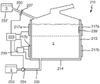
Fig. 4 shows a third exemplary embodiment of a heating device 211 according to the invention, which is designed as an evaporator. For the water 5 to be evaporated, it comprises a short vertical tube 213 corresponding to the fluid chamber, the short vertical tube 213 having a circular cross section. The short vertical tube 213 has a diameter greater than its height, although it may vary significantly. At the top on the outside of the tube 213 or at the circumferential side thereof, the first heating element 217a is arranged around the entire or substantially the entire tube 213. A second correspondingly identically constructed heating element 217b is arranged below. The heating elements 217a and 217b may comprise a plurality of heating conductors having a horizontal parallel profile similar to that of figure 3. The heating elements 217a and 217b are provided with a layer structure corresponding to fig. 2 or are applied externally to the tube 213. The dielectric insulating layer and the conductive connection are not shown. The heating elements 217a and 217b are connected to a control unit 229. The dielectric insulation layer (not shown) is connected to a measuring device 230, which measuring device 230 is in turn connected to a control unit 229. The control unit 229 may comprise, or at least essentially consist of, a controller at least in view of intelligent control functions. In particular, the control unit 229 also controls the operation of the heating elements 217a and 217b, possibly also operating independently of each other. In this respect, reference is made to EP 3278691 A1 with respect to this structure. The water 5 in the pipe 213 is heated and evaporated by means of the heating elements 217a and 217b, so that steam can be discharged from the heating device 211 at the top. In this case, as described previously, temperature monitoring is very important, and for this purpose the invention also works in particular in this case, since an improved accuracy is achieved.
On the inside of the tube 213, at the upper right, a relatively small calcification 239 is shown in a simplified manner. It has the following effects: in this region, the heating element 217a cannot dissipate its heat sufficiently well to the water 5 in the pipe 213, so that overheating or so-called hot spots as described in the introduction may occur here. The calcification can be identified particularly well by the temperature detection according to the invention.
In the heating device 211 according to fig. 4, two possibilities of replenishment with water 5 are implemented. At the lower left there is a water tank 232, the water tank 232 having a pump 234 driven by a control unit 239 for replenishing the fluid chamber of the heating device 211 or the pipe 213 with water 5 from the water tank 232. This is primarily done when it has been determined that the water level in the tube 213 has dropped significantly. This is indicated by the dashed line below the upper heating element 217 a. At the latest, this upper heating element 217a is heavily overheated and water must be replenished to achieve the best function of evaporation and in particular in order to prevent damage caused by overheating. The control unit 229 effects this replenishment of water by means of the pump 234 each time the control unit 229 has identified an elevated temperature.
Alternatively, an additional water tank 232' with water 5 therein is shown at the upper left on the heating device 211. Which is disposed above the tube 213 so that water can automatically flow through the delivery line 235' into the tube 213 or fluid chamber. In this case, the control unit 229 may accordingly open the valve 237 in the transfer line 235'.
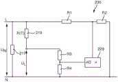
Fig. 5 shows the measuring device 230 in detail, the measuring device 230 in turn being connected to a control unit 229 or a corresponding controller. Voltage U N Is the supply voltage and is applied to the single heating element 217 shown here. If there are a plurality of heating elements, they are very likely to be applied to the supply voltage U in parallel with one another N . Further, the dielectric insulation layer is represented by a temperature dependent resistance R (T) 219. Where a leakage voltage U is applied with respect to ground N L Since in this case the corresponding leakage current flows away through the dielectric insulation layer. To detect this leakage voltage, two resistors R3 and R4 are provided in the measuring device 230 as a voltage divider. The center tap is applied directly to the AD input AD of the controller. This has in fact been explained in the introduction.
A further voltage divider formed by resistors R1 and R2 is provided for connecting the supply voltage U at stage L N And also passes it on to the input of the controller of the control unit 229. Of course, it is easily conceivable in this case that the voltage divider or the voltage divider network or the resistor network formed therefrom can also be constructed differently.
In the control unit 229, the above-described calculation is then carried out with the aid of the read-in voltage signal. In particular, the leakage voltage U L Divided by the measured supply voltage U N And then advantageously multiplies the quotient by the compensation value. For this purpose, the compensation value is chosen to be 230, since the heating device 211 is intended to be supplied with a supply voltage U of 230V N And (5) operating. Thus obtaining a normalized leakage signal. The leakage signal can then be evaluated in terms of its absolute value or in terms of its slope (i.e. the first derivative of the curve). This will be as followsThis is explained by means of fig. 6 and 7. Depending on which known overheating situation is identified therefrom, the fluid chamber may be replenished with water 5, or the heating power of one or all of the heating elements 217 may be reduced or switched off.
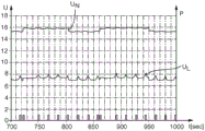
FIG. 6 shows the supply voltage U as a function of time t N And is dependent on the supply voltage U N Leakage voltage U of L The manner of behavior of (c). In this case, the present invention has not been implemented. At the very bottom there is a representation corresponding to the right vertical axis of the active state of the pump 234 of fig. 4, i.e. whether or not it is necessary to pump water again.
In fact, the operation of the evaporator with the heating device 211 is such that pumping is carried out briefly, approximately every 28 seconds, in order to replenish the water. This is shown in the interval between 750 seconds and 850 seconds and over 890 seconds. However, due to the voltage at the power supply U N Particularly when the heating device is arranged in the evaporator inside the furnace, the otherwise powerful heating device of the furnace is switched on or off as a load, which jump is completely non-negligible and therefore malfunctions. Here, these transitions occur upward at about 720 seconds and about 860 seconds. At approximately 805 seconds and 950 seconds, the jump down occurs. This depends precisely on the switching on and off of the further load. It has been found that pump 234 is at supply voltage U N The jump up is followed by a start, in particular at a time slightly longer than 720 seconds and slightly longer than 860 seconds. Thus, pumping occurs prematurely. This has the following disadvantages, among others: i.e. more fluid in the heating device than actually needed or expected, so that more water needs to be heated and evaporation may be slightly reduced. It can also be seen that the leakage voltage U L Is interrupted at exactly these transitions. This leads to just undesired pumping, which is not necessary in practice.
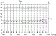
In fig. 7, the compensation or calculation according to the invention has now been carried out. Supply voltage U N Again, but at a slightly different time. However, by inspection and by consideration, it has been found that the supply voltage U at the heating device N Does influence the leakage voltage U L May be controlled in such a way thatThe equation is compensated for so that pumping occurs at pump 234 at the required regular intervals. In particular, this is also at the leakage voltage U L The regularity of the distribution of (c) is shown. When at the power supply voltage U N Leakage voltage U when medium jump occurs L And is not changed. Better temperature detection is thus possible and therefore also better operation of the heating device 211 is possible.
It is easily conceivable that such an effect is also advantageous in detecting hot spots or local overheating, for example due to the calcification 239 corresponding to fig. 4. Leakage voltage U L Due to this overheating, since an increased leakage current flows in this region. It is possible to compensate the supply voltage U at which the heating element operates N And therefore also the corresponding jump in the leakage voltage has to be compensated for.
The same applies to large area calcifications, which lead to an overall slow rise in the leakage voltage due to a slow rise in temperature.
Claims (24)
1. A heating device for a fluid, the heating device comprising a fluid chamber, wherein:
at least one heating element is applied on the outside of the fluid chamber, the heating element having at least one heating conductor,
-the heating means comprises at least one extended dielectric insulation layer substantially covering the at least one heating element,
-the dielectric insulating layer has a temperature dependent resistance,
-at least one electrically conductive connection is arranged on both sides of the dielectric insulation layer,
at least one of the electrically conductive connections is connected to a control unit or a measuring device in order to detect a leakage current as a temperature dependent current flowing through the dielectric insulation layer,
-the control unit of the heating device comprises a controller or microcontroller comprising an AD input,
-a measuring device is provided for measuring the supply voltage of the heating device,
-the measuring means are connected to an AD input,
the control unit is configured such that the measured supply voltage is taken into account when evaluating the temperature at the fluid chamber, which temperature depends on the leakage current.
2. The heating device according to claim 1, wherein the at least one electrically conductive connection is arranged on both sides of the dielectric insulating layer with the same coverage as the dielectric insulating layer, respectively.
3. A heating device as claimed in claim 1 or 2, characterized in that the measuring means comprise a voltage divider with at least two resistors, which are connected to the supply voltage in order to reduce the supply voltage for connection to the AD input.
4. A heating device as claimed in claim 3, characterized in that the voltage divider is constructed as a voltage divider network with three resistors, two resistors being connected in series and one resistor being connected in parallel therewith.
5. A heating device as claimed in claim 1 or 2, wherein the fluid chamber comprises a tube.
6. A heating device as claimed in claim 5, characterized in that the tube is vertical.
7. The heating device of claim 6, wherein the tube has a height greater than a diameter of the tube.
8. A heating device as claimed in claim 5, characterized in that the tube is horizontal.
9. The heating device according to claim 5, characterized in that the at least one heating element is applied on the circumferential outside of the tube.
10. The heating device of claim 9, wherein the bottom of the tube is configured as a down connection to the fluid chamber without heating.
11. A heating device as claimed in claim 1 or 2, characterized in that the fluid chamber comprises a flat bottom, the at least one heating element being applied on the underside of the bottom.
12. A heating device as claimed in claim 1 or 2, characterized in that at least two heating elements are applied on the outside of the fluid chamber, each heating element having a plurality of heating conductors, the two heating elements being drivable individually.
13. The heating device of claim 12, wherein the fluid chamber comprises a tube, the two heating elements being separately drivable and arranged in separate height sections of the fluid chamber or the tube.
14. A heating device as claimed in claim 1 or 2, characterized in that the heating device comprises a pump for pumping water into the fluid chamber, which pump can be driven by the control unit of the heating device.
15. A heating device as claimed in claim 14, characterized in that the heating device comprises a higher positioned fluid tank having a delivery line to the fluid chamber with a valve therein, which valve is correspondingly drivable by the control unit in order to introduce more fluid into the fluid chamber, the pump being drivable by the control unit of the heating device.
16. A heating device as claimed in claim 1 or 2, characterized in that a steam outlet is provided above the fluid chamber as a water chamber.
17. A heating device as claimed in claim 1 or 2, characterized in that the electrically conductive connection is an electrically conductive connection surface.
18. Method for operating a heating device according to claim 1 or 2, with the following steps:
-introducing a fluid into the fluid chamber,
-switching on one of the heating elements,
-detecting a leakage current as a temperature dependent current flowing through the dielectric insulation layer,
-measuring a supply voltage of the heating device,
-taking into account the measured supply voltage when evaluating the temperature at the fluid chamber from the leakage current.
19. The method of claim 18, wherein all of the heating elements of the heating device are initially turned on.
20. Method according to claim 18, characterized in that on the basis of the measured supply voltage and the detected leakage current a leakage signal is calculated in the control unit, by means of which leakage signal the replenishment of the fluid chamber with fluid and/or the driving of the heating element is influenced.
21. The method of claim 18, wherein the temperature at the dielectric insulation layer is monitored by evaluating the leakage current in terms of absolute level and/or slope.
22. The method of claim 18, wherein:
-converting the leakage current into a leakage voltage by means of a resistor,
-dividing the converted leakage voltage by the measured supply voltage,
-subsequently multiplying the obtained quotient by the compensation value in order to obtain a normalized leakage signal, which is normalized to the base value of the supply voltage,
-using a normalized leakage signal if a certain absolute value of the leakage signal is exceeded or if a certain slope of the leakage signal is exceeded, in order to replenish the fluid chamber with more fluid and/or to reduce the heating power of at least one heating element and/or to identify the degree of calcification on the wall of the fluid chamber.
23. The method according to claim 22, characterized in that in case the normalized leakage signal exceeds a first limit value as an indication of a too high temperature, the fluid chamber is replenished with more fluid, and the replenishment is stopped when the normalized leakage current has returned below the first limit value.
24. The method of claim 22, wherein in the event that the slope of the normalized leakage signal profile exceeds a second limit value that is an indication of an excessive rise in temperature, the fluid chamber is replenished with more fluid, and the replenishment is stopped when the slope of the normalized leakage signal profile has returned below the second limit value.
Applications Claiming Priority (2)
| Application Number | Priority Date | Filing Date | Title |
|---|---|---|---|
| DE102018213869.9 | 2018-08-17 | ||
| DE102018213869.9A DE102018213869B4 (en) | 2018-08-17 | 2018-08-17 | Heating device and method for operating a heating device |
Publications (2)
| Publication Number | Publication Date |
|---|---|
| CN110836532A CN110836532A (en) | 2020-02-25 |
| CN110836532B true CN110836532B (en) | 2023-03-10 |
Family
ID=67514288
Family Applications (1)
| Application Number | Title | Priority Date | Filing Date |
|---|---|---|---|
| CN201910763938.1A Active CN110836532B (en) | 2018-08-17 | 2019-08-19 | Heating device and method for operating a heating device |
Country Status (6)
| Country | Link |
|---|---|
| US (1) | US11585574B2 (en) |
| EP (1) | EP3614797B1 (en) |
| KR (1) | KR20200020642A (en) |
| CN (1) | CN110836532B (en) |
| DE (1) | DE102018213869B4 (en) |
| PL (1) | PL3614797T3 (en) |
Families Citing this family (2)
| Publication number | Priority date | Publication date | Assignee | Title |
|---|---|---|---|---|
| DE102020207784A1 (en) * | 2020-06-23 | 2021-12-23 | E.G.O. Elektro-Gerätebau GmbH | Heating device with a temperature measuring device and method for temperature measurement on the heating device and for production |
| CN112462824A (en) * | 2020-11-12 | 2021-03-09 | 宣城睿晖宣晟企业管理中心合伙企业(有限合伙) | Heating control system and method for thin film deposition equipment |
Citations (12)
| Publication number | Priority date | Publication date | Assignee | Title |
|---|---|---|---|---|
| CN2056983U (en) * | 1989-05-18 | 1990-05-09 | 陈非 | Full-automatic electrothermic shower |
| JP2004281121A (en) * | 2003-03-13 | 2004-10-07 | Sanyo Electric Co Ltd | Ground-fault interrupter |
| CN1937860A (en) * | 2005-09-23 | 2007-03-28 | 凯特姆两合公司 | Heat-generating element of a heating device |
| CN1991272A (en) * | 2005-12-07 | 2007-07-04 | Aos控股公司 | Fluid-heating apparatus, circuit for heating a fluid, and method of operating the same |
| CN200950672Y (en) * | 2006-05-23 | 2007-09-19 | 费罗技术控股公司 | Electric heating unit for performing temperature detection through dielectric layer |
| CN101061076A (en) * | 2004-11-23 | 2007-10-24 | 费罗技术控股公司 | Heating element and method for detecting temperature changes |
| CN101576430A (en) * | 2008-05-06 | 2009-11-11 | 中央制御株式会社 | Leakage detection equipment |
| CN102160456A (en) * | 2008-07-15 | 2011-08-17 | 奥特控制有限公司 | Heating element and method for operating such a heating element |
| JP2012178365A (en) * | 2012-06-13 | 2012-09-13 | Mitsubishi Electric Corp | Induction heating cooker |
| CN105229883A (en) * | 2013-04-19 | 2016-01-06 | 科模热思股份有限公司 | Middle voltage heating element moisture detection circuit |
| CN106993995A (en) * | 2015-09-21 | 2017-08-01 | E.G.O.电气设备制造股份有限公司 | For heating the heater of water and method for operating such heater |
| EP3278691A1 (en) * | 2016-08-02 | 2018-02-07 | E.G.O. ELEKTRO-GERÄTEBAU GmbH | Evaporator device for water and cooking device with same |
Family Cites Families (17)
| Publication number | Priority date | Publication date | Assignee | Title |
|---|---|---|---|---|
| US4092520A (en) * | 1976-12-16 | 1978-05-30 | Baxter Travenol Laboratories, Inc. | Leakage current thermostat |
| JP2652430B2 (en) * | 1988-10-21 | 1997-09-10 | 松下電工株式会社 | Multi-division heat-sensitive sheet heating element |
| DE19612170A1 (en) * | 1996-03-27 | 1997-10-02 | Patent Treuhand Ges Fuer Elektrische Gluehlampen Mbh | Circuit arrangement for operating electric lamps and operating methods for electric lamps |
| JPH10247579A (en) * | 1997-03-05 | 1998-09-14 | Furukawa Electric Co Ltd:The | Electric heater |
| WO1999027828A1 (en) * | 1997-12-02 | 1999-06-10 | Koninklijke Philips Electronics N.V. | Heating vessel and method of controlling the heating element of such a vessel |
| IT1306477B1 (en) * | 1998-10-13 | 2001-06-11 | Hydor Srl | THERMOSTATIC HEATER DEVICE FOR LIQUIDS, IN PARTICULAR FOR AQUARIUM WATER. |
| NL1014601C2 (en) | 2000-03-10 | 2001-09-11 | Ferro Techniek Bv | Heating element, liquid container and method for detecting temperature changes. |
| DE10021512A1 (en) | 2000-05-03 | 2001-11-08 | Ego Elektro Geraetebau Gmbh | Electric heating unit, especially for liquid media |
| US7576305B2 (en) | 2006-09-22 | 2009-08-18 | Catem Gmbh & Co. Kg | Heat-generating element of a heating device |
| US8378271B2 (en) | 2007-07-11 | 2013-02-19 | International Business Machines Corporation | Utilization of overvoltage and overcurrent compensation to extend the usable operating range of electronic devices |
| JP2011058962A (en) * | 2009-09-10 | 2011-03-24 | Kurimoto Ltd | Method of measuring material temperature in direct resistance heater using rectifier-type dc power supply and measuring instrument therefor |
| DE102010043727A1 (en) * | 2010-11-10 | 2012-05-10 | E.G.O. Elektro-Gerätebau GmbH | pump |
| DE102012213385A1 (en) * | 2012-07-30 | 2014-05-22 | E.G.O. Elektro-Gerätebau GmbH | Heating and electrical appliance with heating device |
| DE102013200277A1 (en) * | 2013-01-10 | 2014-01-30 | E.G.O. Elektro-Gerätebau GmbH | Heating device has measuring device that is connected to planar electrode and heating conductor, for detecting temperature dependent current flow between heating conductor and covering layer and/or dielectric insulation layer |
| DE102013201903A1 (en) * | 2013-02-06 | 2014-08-07 | E.G.O. Elektro-Gerätebau GmbH | Heat pump device, use of a pump with heatable pumping chamber in a heat pump device and method of operating a heat pump device |
| EP3096585B1 (en) * | 2015-05-18 | 2017-12-20 | E.G.O. ELEKTRO-GERÄTEBAU GmbH | Heating device for heating fluids and a method for operating such a heating device |
| PL3197241T3 (en) * | 2016-01-19 | 2020-11-16 | E.G.O. Elektro-Gerätebau GmbH | Heating device and method for measuring the temperature on the heating element |
-
2018
- 2018-08-17 DE DE102018213869.9A patent/DE102018213869B4/en active Active
-
2019
- 2019-07-29 EP EP19188759.5A patent/EP3614797B1/en active Active
- 2019-07-29 PL PL19188759.5T patent/PL3614797T3/en unknown
- 2019-08-15 US US16/541,246 patent/US11585574B2/en active Active
- 2019-08-16 KR KR1020190100481A patent/KR20200020642A/en unknown
- 2019-08-19 CN CN201910763938.1A patent/CN110836532B/en active Active
Patent Citations (12)
| Publication number | Priority date | Publication date | Assignee | Title |
|---|---|---|---|---|
| CN2056983U (en) * | 1989-05-18 | 1990-05-09 | 陈非 | Full-automatic electrothermic shower |
| JP2004281121A (en) * | 2003-03-13 | 2004-10-07 | Sanyo Electric Co Ltd | Ground-fault interrupter |
| CN101061076A (en) * | 2004-11-23 | 2007-10-24 | 费罗技术控股公司 | Heating element and method for detecting temperature changes |
| CN1937860A (en) * | 2005-09-23 | 2007-03-28 | 凯特姆两合公司 | Heat-generating element of a heating device |
| CN1991272A (en) * | 2005-12-07 | 2007-07-04 | Aos控股公司 | Fluid-heating apparatus, circuit for heating a fluid, and method of operating the same |
| CN200950672Y (en) * | 2006-05-23 | 2007-09-19 | 费罗技术控股公司 | Electric heating unit for performing temperature detection through dielectric layer |
| CN101576430A (en) * | 2008-05-06 | 2009-11-11 | 中央制御株式会社 | Leakage detection equipment |
| CN102160456A (en) * | 2008-07-15 | 2011-08-17 | 奥特控制有限公司 | Heating element and method for operating such a heating element |
| JP2012178365A (en) * | 2012-06-13 | 2012-09-13 | Mitsubishi Electric Corp | Induction heating cooker |
| CN105229883A (en) * | 2013-04-19 | 2016-01-06 | 科模热思股份有限公司 | Middle voltage heating element moisture detection circuit |
| CN106993995A (en) * | 2015-09-21 | 2017-08-01 | E.G.O.电气设备制造股份有限公司 | For heating the heater of water and method for operating such heater |
| EP3278691A1 (en) * | 2016-08-02 | 2018-02-07 | E.G.O. ELEKTRO-GERÄTEBAU GmbH | Evaporator device for water and cooking device with same |
Also Published As
| Publication number | Publication date |
|---|---|
| DE102018213869B4 (en) | 2020-03-05 |
| US11585574B2 (en) | 2023-02-21 |
| DE102018213869A1 (en) | 2020-02-20 |
| EP3614797B1 (en) | 2022-04-20 |
| PL3614797T3 (en) | 2022-09-12 |
| EP3614797A1 (en) | 2020-02-26 |
| CN110836532A (en) | 2020-02-25 |
| US20200056811A1 (en) | 2020-02-20 |
| KR20200020642A (en) | 2020-02-26 |
Similar Documents
| Publication | Publication Date | Title |
|---|---|---|
| US7256372B2 (en) | Fluid-heating apparatus, circuit for heating a fluid, and method of operating the same | |
| US20170086257A1 (en) | Heating device for heating water and method for operating a heating device of this kind | |
| CN110836532B (en) | Heating device and method for operating a heating device | |
| US20160316516A1 (en) | Heating device for heating liquids, evaporator for an electric cooking appliance and method for operating a heating device | |
| RU2717955C2 (en) | Heating device for heating fluids and a method of controlling such a device | |
| US9288846B2 (en) | Induction cooker and method of operation | |
| EP2378836B1 (en) | Inductive heating apparatus | |
| JP5128589B2 (en) | Home appliances for liquid heating | |
| US7941884B2 (en) | Method for operating a washing machine having a heating unit | |
| RU2480544C2 (en) | Washing machine, in particular, washing or washing-drying machine for laundry or dishwasher, method of determining submerged or protruding condition of electrical resistance used in washing machine, method for removal of lime deposits from electrical resistance | |
| US11622421B2 (en) | Electric heaters with low drift resistance feedback | |
| US20140029928A1 (en) | Heating device and electric appliance with heating device | |
| JP7073329B2 (en) | Adaptive control heater bundle and current leakage reduction method | |
| EP1266542B1 (en) | Heating element, liquid container and method for detecting temperature changes | |
| US20220071433A1 (en) | A liquid heating appliance for making a beverage and associated method, power management system and microcontroller readable medium | |
| CN111024254A (en) | Heating device and method for temperature detection at a heating device | |
| KR101113018B1 (en) | Electric heater, temperature control module, and method for controlling the temperature of the electric heater | |
| US20210396599A1 (en) | Heating device comprising a temperature measuring device and methods for temperature measurement at the heating device and for production | |
| JP4794681B1 (en) | Induction heating cooker | |
| JP2016200049A (en) | Submerged pump control device and submerged pump control method | |
| WO2023158814A1 (en) | Steam generator | |
| CN106821258A (en) | Water flow temperature detection means and method in dish-washing machine and the pump housing | |
| JPH0646661U (en) | Water level detector for dishwasher | |
| ITRM20100363A1 (en) | WATER HEATING SYSTEM, IN PARTICULAR FOR DISHWASHER |
Legal Events
| Date | Code | Title | Description |
|---|---|---|---|
| PB01 | Publication | ||
| PB01 | Publication | ||
| SE01 | Entry into force of request for substantive examination | ||
| SE01 | Entry into force of request for substantive examination | ||
| GR01 | Patent grant | ||
| GR01 | Patent grant |