EP3614100A1 - Device for levelling cast material such as flowing plaster, pumping concrete or the like and measuring device comprising such a device - Google Patents
Device for levelling cast material such as flowing plaster, pumping concrete or the like and measuring device comprising such a device Download PDFInfo
- Publication number
- EP3614100A1 EP3614100A1 EP19191901.8A EP19191901A EP3614100A1 EP 3614100 A1 EP3614100 A1 EP 3614100A1 EP 19191901 A EP19191901 A EP 19191901A EP 3614100 A1 EP3614100 A1 EP 3614100A1
- Authority
- EP
- European Patent Office
- Prior art keywords
- marking
- leveling
- height
- casting compound
- measuring device
- Prior art date
- Legal status (The legal status is an assumption and is not a legal conclusion. Google has not performed a legal analysis and makes no representation as to the accuracy of the status listed.)
- Granted
Links
- 239000000463 material Substances 0.000 title 1
- 239000011505 plaster Substances 0.000 title 1
- 238000005086 pumping Methods 0.000 title 1
- 238000005266 casting Methods 0.000 claims abstract description 70
- 150000001875 compounds Chemical class 0.000 claims abstract description 54
- 239000007788 liquid Substances 0.000 claims abstract description 17
- 230000008878 coupling Effects 0.000 claims description 15
- 239000007819 coupling partner Substances 0.000 claims description 15
- 238000010168 coupling process Methods 0.000 claims description 15
- 238000005859 coupling reaction Methods 0.000 claims description 15
- 230000003993 interaction Effects 0.000 claims description 6
- GHYOCDFICYLMRF-UTIIJYGPSA-N (2S,3R)-N-[(2S)-3-(cyclopenten-1-yl)-1-[(2R)-2-methyloxiran-2-yl]-1-oxopropan-2-yl]-3-hydroxy-3-(4-methoxyphenyl)-2-[[(2S)-2-[(2-morpholin-4-ylacetyl)amino]propanoyl]amino]propanamide Chemical compound C1(=CCCC1)C[C@@H](C(=O)[C@@]1(OC1)C)NC([C@H]([C@@H](C1=CC=C(C=C1)OC)O)NC([C@H](C)NC(CN1CCOCC1)=O)=O)=O GHYOCDFICYLMRF-UTIIJYGPSA-N 0.000 description 16
- 229940125797 compound 12 Drugs 0.000 description 16
- -1 liquid screed Chemical class 0.000 description 8
- 238000004140 cleaning Methods 0.000 description 6
- 239000003550 marker Substances 0.000 description 4
- 230000003287 optical effect Effects 0.000 description 3
- 206010017577 Gait disturbance Diseases 0.000 description 2
- 230000005540 biological transmission Effects 0.000 description 2
- SZUVGFMDDVSKSI-WIFOCOSTSA-N (1s,2s,3s,5r)-1-(carboxymethyl)-3,5-bis[(4-phenoxyphenyl)methyl-propylcarbamoyl]cyclopentane-1,2-dicarboxylic acid Chemical compound O=C([C@@H]1[C@@H]([C@](CC(O)=O)([C@H](C(=O)N(CCC)CC=2C=CC(OC=3C=CC=CC=3)=CC=2)C1)C(O)=O)C(O)=O)N(CCC)CC(C=C1)=CC=C1OC1=CC=CC=C1 SZUVGFMDDVSKSI-WIFOCOSTSA-N 0.000 description 1
- 238000006243 chemical reaction Methods 0.000 description 1
- 230000001427 coherent effect Effects 0.000 description 1
- 229940126543 compound 14 Drugs 0.000 description 1
- 230000001419 dependent effect Effects 0.000 description 1
- 230000000694 effects Effects 0.000 description 1
- 230000010354 integration Effects 0.000 description 1
- 238000005259 measurement Methods 0.000 description 1
- 238000000034 method Methods 0.000 description 1
- 230000005855 radiation Effects 0.000 description 1
- 238000007789 sealing Methods 0.000 description 1
- 239000007787 solid Substances 0.000 description 1
Images


Classifications
-
- G—PHYSICS
- G01—MEASURING; TESTING
- G01C—MEASURING DISTANCES, LEVELS OR BEARINGS; SURVEYING; NAVIGATION; GYROSCOPIC INSTRUMENTS; PHOTOGRAMMETRY OR VIDEOGRAMMETRY
- G01C15/00—Surveying instruments or accessories not provided for in groups G01C1/00 - G01C13/00
- G01C15/002—Active optical surveying means
- G01C15/004—Reference lines, planes or sectors
-
- E—FIXED CONSTRUCTIONS
- E04—BUILDING
- E04G—SCAFFOLDING; FORMS; SHUTTERING; BUILDING IMPLEMENTS OR AIDS, OR THEIR USE; HANDLING BUILDING MATERIALS ON THE SITE; REPAIRING, BREAKING-UP OR OTHER WORK ON EXISTING BUILDINGS
- E04G21/00—Preparing, conveying, or working-up building materials or building elements in situ; Other devices or measures for constructional work
- E04G21/02—Conveying or working-up concrete or similar masses able to be heaped or cast
- E04G21/10—Devices for levelling, e.g. templates or boards
-
- G—PHYSICS
- G01—MEASURING; TESTING
- G01C—MEASURING DISTANCES, LEVELS OR BEARINGS; SURVEYING; NAVIGATION; GYROSCOPIC INSTRUMENTS; PHOTOGRAMMETRY OR VIDEOGRAMMETRY
- G01C5/00—Measuring height; Measuring distances transverse to line of sight; Levelling between separated points; Surveyors' levels
Definitions
- the present invention relates to a device for leveling casting compounds such as liquid screed, pumped concrete or the like. Furthermore, the invention relates to a measuring device with such a device.
- leveling should be understood to mean filling in particular a space with the casting compound to the desired height.
- Floating screed is an example of pouring compound to be emphasized.
- a pouring compound is to be understood as a mass which is so liquid when introduced into the room that it can be conveyed by means of a feed pump. Once the desired volume of casting compound has been introduced into the room, the casting compound is allowed to dry for a certain time, as a result of which the casting compound hardens. Due to the fact that the casting compound is liquid during introduction into the room, it distributes itself more or less quickly evenly in the room and assumes a uniform level. It is therefore not necessary to smooth the casting compound.
- leveling blocks In order to be able to level a room to the desired height with liquid screed, so-called leveling blocks are used, such as those from the DE 100 49 867 A1 or the DE 200 17 303 U1 are known.
- leveling brackets usually have three legs on which a threaded rod is attached, along which a level plate can be moved by turning.
- the leveling stand is placed on the floor of the room that is to be filled with the casting compound.
- the casting compound is pumped into the room with a feed pump until the surface of the casting compound is flush with the leveling disc.
- the casting mass is now at the desired height. Then the leveling stand is removed.
- a device which is not unlike a trestle is in the US 6 760 974 B1 disclosed.
- This device has a plurality of tubes arranged telescopically and displaceable relative to one another.
- the pipes are arranged vertically when used as intended.
- At the bottom tube there is a base that can be placed on the floor of the room.
- a height indicator is arranged on the lowest tube, which has a similar function as the leveling disc of a leveling block.
- the height indicator can be adjusted to the desired height by moving the pipes relative to each other. With the help of locking elements, the displaceability of the pipes can be prevented if the height indicator is set to the desired height. Similar to the leveling stand, the desired height of the casting compound is reached when the surface of the casting compound is flush with the height indicator.
- a leveling block allows the casting compound to be leveled only at one point in the room.
- the height of the casting compound should be determined at several points in the room. Therefore, several leveling stands are used.
- the leveling blocks of the respective rooms must be set to a different level, which is cumbersome and time-consuming and can cause errors.
- leveling trestles represent a certain obstacle. It is not uncommon for people to get caught on the leveling trestles and stumble. If the leveling bracket falls into the liquid screed when it falls over, the leveling bracket must then be cleaned thoroughly and time-consuming.
- the casting compound has the desired height when it is flush with the level plate.
- the leveling stand is therefore up to the level disc in the casting compound, so that it must be cleaned thoroughly even after operation. The more leveling blocks are used, the greater the cleaning effort.
- AT 514 294 A1 discloses a device for leveling fill, in which a pull-off strip is pulled over the fill in a manner similar to a rake in order to bring it to a uniform height.
- the device disclosed there is only suitable for solids, but not for casting compounds which can be conveyed with a feed pump.
- An object of an embodiment of the present invention is to provide a device with which it is possible with simple means to cast a casting compound with high accuracy and reliability with a reduced expenditure of time compared to the leveling trestles discussed above to level. In particular, the cleaning effort should be reduced and the risk of getting caught and stumbling should be prevented. Furthermore, an embodiment of the present invention has for its object to provide a measuring device which, even in large rooms and in several rooms with different floor levels, enables a casting compound to be leveled in a simple and at least almost error-free manner with little expenditure of time.
- One embodiment of the invention relates to a device for leveling casting compounds such as self-leveling screed, pumped concrete or the like, comprising a buoyancy body which floats on the casting compound to be leveled, a marking section which is designed as a marking body connected to the buoyancy body or is formed by the buoyancy body, and a marking arranged on the marking section, with which the height of the casting compound can be determined.
- the buoyancy body is plate-shaped or disk-shaped.
- the marking body can be designed as a tube or funnel-shaped.
- the sources used to determine the height of the casting compound for generating electromagnetic waves may only be arranged at a certain distance from the floor of the space to be filled with the casting compound. To bridge the gap, the marker body must be made long enough. Adjusting the length of the marker body is very easy to do with a tube.
- the marking on the pipe can be read equally well from all sides. In addition, a pipe can be easily gripped so that the device is easy to handle.
- the diameter of the marking body widens towards the buoyancy body. Ideally, the funnel-shaped marking body is flush with the buoyancy body.
- the funnel-shaped design has the additional advantage that the casting compound can run off and areas that are difficult to access can be avoided.
- the surface of the marking body can be flat in relation to a sectional plane running through the central axis of the marking body, so that a conical section is created. Alternatively, the surface can be curved. It also increases the funnel-shaped Design of the marker body, the stability of the device.
- the buoyancy body and the marking body can be designed as separate components and connected to one another by suitable means.
- the bodies of the device do not have to be connected to one another in an additional operation. Detachment of the bodies from one another is also prevented.
- a further developed embodiment is characterized in that the device has a coupling unit for coupling the device to a coupling partner.
- the proposed device floats on the casting compound. It is therefore located close to the ground.
- the coupling partner can comprise a rod which can interact with the coupling unit. With the coupling partner, the device can be quickly and easily distributed in the room. It is therefore possible in a simple manner to determine the height of the casting compound at several points in the room with only one device during the filling of the casting compound, as a result of which the determination is very precise.
- the coupling unit is designed as a hook or an eyelet.
- Hooks and eyes are simple embodiments of the coupling unit that can be gripped well with the coupling partner. Also detaching the coupling partner from the coupling unit is easy to do. Alternatively, magnets or the like can also be used.
- Another embodiment is characterized in that the marking is designed for interaction with electromagnetic waves.
- the use of electromagnetic waves enables very precise leveling, since these can be emitted in a very precisely defined plane with almost no height deviations.
- the waves have no significant disturbing influence on the work to be carried out in the room.
- the proposed device can be used for very precise leveling in this embodiment.
- the interaction with the electromagnetic waves can take place, for example, in that the electromagnetic waves are reflected in a defined manner by the marking, so that the reflected electromagnetic waves can be received by a detector when the electromagnetic waves hit the marking. When the electromagnetic waves hit the marking, the desired height of the casting mass is reached.
- the device has a sensor which registers the interaction of the marking with the electromagnetic waves and which generates a corresponding signal.
- the sensor can be configured as a photodiode.
- the photodiode When a light beam hits the marking, the photodiode generates a corresponding signal, which can be transmitted to a receiver, for example, which emits an acoustic or optical signal.
- the receiver can be arranged in the device itself, but the receiver can also be located at the light source or at any one other device. Integration into a smartphone application is conceivable, so that a responsible person receives an indication that the casting compound has reached the desired height, even if this person is further away from the rooms in question.
- One embodiment of the invention relates to a measuring device for leveling casting compounds such as self-leveling screed, pump concrete or the like, comprising a source for generating and for the height-defined transmission of electromagnetic waves, and at least one device according to one of the preceding embodiments, the marking with the electromagnetic waves for leveling the casting compounds interact.
- the source with which the electromagnetic waves are generated must be aligned as precisely as possible horizontally and brought to a height which, when the electromagnetic waves interact with the marking, indicates that the casting compound has reached the desired height. It is sufficient to use only one device, while when using leveling trestles, in particular in larger or several rooms, each of the leveling trestles used has to be set to the desired height of the casting compound. When using the proposed device, this is not necessary even if Rooms with different floor levels are to be filled with the casting compound.
- the source can be designed as a laser source that generates laser beams.
- Laser beams are often used to determine distances, so that laser sources are widespread and therefore quickly and inexpensively available.
- the measuring device comprises a stand for receiving the source.
- the tripod ensures that the source is safely picked up and the risk of tipping over is kept low.
- the stand has a height-adjustable holder for the source.
- the electromagnetic waves can be emitted horizontally at the desired height with sufficient accuracy.
- the measuring device comprises a coupling partner for coupling with the device.
- the coupling partner can comprise a rod which can interact with the coupling unit.
- the device can be quickly and easily distributed and collected in the room without a person having to bend down.
- FIG. 1 A first exemplary embodiment of a device 10 1 according to the invention for leveling casting compounds 12 such as liquid screed, pumped concrete or the like (see FIG. 6) is shown on the basis of a basic side view.
- the device 10 1 comprises a buoyancy body 14, which floats on the casting compound 12 to be leveled, a marking section 16, which as one with the buoyancy body 14 connected marking body 18 is formed, and a marking 20 arranged on the marking section 16, with which the height of the casting compound 12 can be determined.
- the marking 20 is designed as a colored line, in particular as a black line that stands out clearly from the marking body 18.
- the buoyancy body 14 is plate-shaped and has a rectangular cross section in the plan view (see Figure 5 ).
- the buoyancy provided by the buoyancy body 14 is selected in such a way that it holds the entire device 10 1 upright on the casting compound 12 and virtually does not immerse into the casting compound 12.
- the device 10 1 and in particular the buoyancy body 14 are designed such that the underside of the buoyancy body 14 is almost flush with the surface of the casting compound 12 (cf. Figure 6 ).
- the marking body 18 is designed as a tube 22 and connected to the buoyancy body 14 in a suitable manner.
- the tube 22 can be welded to the buoyancy body 14.
- the marking 20 is arranged on the tube 22.
- An embodiment is not shown in which the marking body 18 and the buoyancy body 14 are made in one piece.
- the device 10 1 has a coupling unit 24, which in the exemplary embodiments shown is designed as a hook 26.
- FIG. 2 A second exemplary embodiment of the device 10 2 according to the invention is shown on the basis of a basic side sectional view.
- the structure of the device 10 1 according to the second embodiment essentially corresponds the structure of the device 10 1 according to the first embodiment, the marking body 18 of the device 10 2 according to the second embodiment being funnel-shaped.
- the diameter of the marking body 18 initially remains constant, so that the marking body 18 in the second exemplary embodiment has a tubular section. Thereafter, the diameter of the marking body 18 increases constantly towards the buoyancy body 14 until the diameter of the marking body 18 and the buoyancy body 14 are the same. Consequently, the marking body 18 has a funnel-shaped and in this case conical section. This increases the stability of the device 10 2 and simplifies cleaning due to the good accessibility of the surfaces.
- the device 10 2 according to the second embodiment is made in one piece, the buoyancy body 14 and the marking body 18 consequently form a coherent component.
- FIG 3 A third exemplary embodiment of a device 10 3 according to the invention is shown on the basis of a basic side view.
- the structure of the device 10 3 according to the third exemplary embodiment essentially corresponds to the structure of the device 10 1 according to the first exemplary embodiment, the marking 20 being designed for interaction with electromagnetic waves 40 (see Figure 5 ).
- the marking 20 does not necessarily have to be visible to the human eye.
- the device 10 3 has a sensor 30 which monitors the interaction the mark 20 registered with the electromagnetic waves 40 and which generates a corresponding signal.
- a coupling partner 32 is shown on the basis of a basic illustration, which can be coupled to the device 10 according to one of the exemplary embodiments.
- the coupling partner 32 has a rod 33, on which a hook 34 is arranged at one end, which can be brought into engagement with the hook 26 of the device 10.
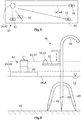
- Figure 5 shows a basic plan view and Figure 6 a side view of a measuring device 36 according to the invention for leveling casting compounds 12 such as liquid screed, pumped concrete or the like.
- the measuring device 36 comprises a source 38 for generating and for the height-defined transmission of electromagnetic waves 40 and a device 10 according to one of the previous exemplary embodiments.
- the Figure 5 is to be understood in such a way that the same device 10 is arranged at different times in four different locations. Alternatively, several devices 10 can also be used at the same time, but this is not absolutely necessary.
- the source 38 is designed as a laser source 42, which generates laser beams 44 and emits them in 360 °.
- the measuring device 36 comprises a height-adjustable stand 46 for receiving the source 38, the stand 46 having three legs 48 which taper to a point at their free ends. It should be noted that the illustrated relationship of the stand 46 to the device 10 does not correspond to the actual conditions. Usually the device 10 and the stand 46 are approximately the same height.
- the measuring device 36 is operated in the following way:
- the stand 46 is placed on a floor 49 of a room 50 which is to be filled with a casting compound 12, for example with a liquid screed.
- the laser source 42 is then firmly connected to a receptacle 52 of the stand 46.
- the laser source 42 can be self-leveling, so that it is not necessary to align the laser source 42 exactly horizontally.
- the receptacle 52 is adjustable in height. The procedure for arranging the laser source 42 at the correct height is as follows.
- a so-called meter crack can be used as the starting point for the calculation of the height at which the laser source 42 has to be arranged, which is to be understood as meaning a line marking applied to the walls of a shell.
- a meter crack with the designation OKFF + 1.00 m can be used, the designation OKFF standing for "top edge of the finished floor”.
- the meter crack OKFF + 1.00 m is therefore 1 m above the top edge of the finished floor.
- the height of the floor covering for example a laminate of 0.01 m height
- the value is 1.01 m, which has to be subtracted from the meter crack OKFF + 1m.
- This value still has to be corrected by the height HM of the marking 20 of the device 10, which can be, for example, 0.2 m.
- the laser source 42 must therefore be set to a height of 0.81 m below the meter crack so that the laser beam 44 hits the marking 20 when the desired height HGW of the casting compound 12 has been reached.
- the distance of 0.81 m below the meter crack can be marked by means of a line on the wall of the room, so that the laser beams 44 emitted by the laser source 42 can be aligned with this line.
- the laser source 42 After the laser source 42 has been aligned, one of the devices 10 according to the invention with the coupling partner 24 is arranged anywhere in the room 50.
- the laser source 42 is now switched on. Like from the Figures 5 and 6 As can be seen, the laser source 42 emits the laser beams 44 in an almost horizontal plane through the entire or almost the entire space 50, wherein a sector-shaped radiation is also conceivable.
- the casting compound 12 is conveyed into the space 50 by means of a feed pump, not shown.
- the level of the casting compound 12 gradually increases.
- the current height of the casting compound 12 is in Figure 6 designated with HGA.
- the device 10 As the volume of the casting compound 12 pumped into the space 50, the device 10 is also raised.
- the laser beams 44 strike the marking 20 of the device 10 when the casting compound 12 has reached the desired height HGW.
- the marker 20 is not designed to interact with the laser beams 44, the person must observe the device 10 and check the position of the laser beams 44. If it detects that the laser beams 44 hit the mark 20 or are just before it, it switches off the feed pump. In order to make it easier to check the position of the laser beams 44 on the marking section 16, the latter can be designed in particular in terms of color that the laser beams 44 are particularly well visible when they hit the marking 20.
- the marking 20 is designed to interact with the electromagnetic waves 40, in this case with the laser beams 44.
- the sensor 30 registers the impact of the laser beams 44 on the marking 20 and generates a corresponding signal, for example an optical or an acoustic signal.
- the device 10 3 according to the third exemplary embodiment has two LEDs 58 (see Figure 3 ), which in this case output an optical signal.
- the lower one of the LEDs 58 can light up when the casting compound 12 has not yet reached the desired height HMW. If the desired height HMW is exceeded, the upper of the LEDs 58 can light up. If the desired height HMW is reached, a responsible person can stop the feed pump. Alternatively or cumulatively, the sensor 30 can also generate a radio signal which is sent to a person's smartphone.
- the person collects the device 10 with the coupling partner 32 and takes the stand 46 together with the laser source 42 from the casting compound 12 Figure 6 recognizable, the stand 46 has a holding section 56 with which the person can grip the stand 46.
- the desired height HGW of the casting compound 12 is usually not very large. Typical heights, which can also be referred to as layer thicknesses, are between 2 and 20 cm, in most cases the layer thicknesses being less than 7 cm.
- the tripod 46 must be designed so that the Laser source 42 can be arranged at a correspondingly small distance above the floor 49 of the room 50.
- the height HM of the marking can also be adapted so that the desired height of the casting compound can be determined with commercially available laser sources and with the necessary precision, even in the case of thin layers.
- the marking body 18 designed as the tube 22 can be made correspondingly longer. It is also conceivable to plug an extension onto the marking body 18, which has a marking, so as to increase the height HM of the marking.
Landscapes
- Engineering & Computer Science (AREA)
- Physics & Mathematics (AREA)
- General Physics & Mathematics (AREA)
- Radar, Positioning & Navigation (AREA)
- Remote Sensing (AREA)
- Architecture (AREA)
- Mechanical Engineering (AREA)
- Civil Engineering (AREA)
- Structural Engineering (AREA)
- Measurement Of Levels Of Liquids Or Fluent Solid Materials (AREA)
- On-Site Construction Work That Accompanies The Preparation And Application Of Concrete (AREA)
- Road Paving Machines (AREA)
- Level Indicators Using A Float (AREA)
Abstract
Die vorliegende Erfindung betrifft eine Vorrichtung (10) zum Nivellieren von Gussmassen (12) wie Fließestrich, Pumpbeton oder dergleichen, umfassend einen Auftriebskörper (14), welcher auf der zu nivellierenden Gussmasse (12) schwimmt, einen Markierungsabschnitt (16), welcher als ein mit dem Auftriebskörper (14) verbundener Markierungskörper (18) ausgebildet ist oder vom Auftriebskörper (14) gebildet wird, und eine auf dem Markierungsabschnitt (16) angeordnete Markierung (20), mit welcher die Höhe der Gussmasse (12) bestimmbar ist. Weiterhin betrifft die Erfindung eine Messeinrichtung (36) mit einer derartigen Vorrichtung (10).The invention relates to a device (10) for leveling casting compounds (12) such as liquid screed, pumped concrete or the like, comprising a buoyancy body (14) which floats on the casting compound (12) to be leveled, a marking section (16) which acts as a a marking body (18) connected to the buoyancy body (14) is formed or is formed by the buoyancy body (14), and a marking (20) arranged on the marking section (16), with which the height of the casting compound (12) can be determined. The invention further relates to a measuring device (36) with such a device (10).
Description
Die vorliegende Erfindung betrifft eine Vorrichtung zum Nivellieren von Gussmassen wie Fließestrich, Pumpbeton oder dergleichen. Weiterhin betrifft die Erfindung eine Messeinrichtung mit einer derartigen Vorrichtung.The present invention relates to a device for leveling casting compounds such as liquid screed, pumped concrete or the like. Furthermore, the invention relates to a measuring device with such a device.
Unter Nivellieren soll im Folgenden das Ausfüllen insbesondere eines Raums mit der Gussmasse auf die gewünschte Höhe verstanden werden. Ein hervorzuhebendes Beispiel von Gussmassen stellt Fließestrich dar. Unter einer Gussmasse soll eine Masse verstanden werden, welche beim Einbringen in den Raum so flüssig ist, dass sie mittels einer Förderpumpe förderbar ist. Ist das gewünschte Volumen an Gussmasse in den Raum eingebracht, lässt man die Gussmasse für eine bestimmte Zeit trocknen, wodurch die Gussmasse aushärtet. Aufgrund der Tatsache, dass die Gussmasse während des Einbringens in den Raum flüssig ist, verteilt sie sich mehr oder weniger schnell gleichmäßig im Raum und nimmt ein einheitliches Niveau ein. Es ist daher nicht notwendig, die Gussmasse zu glätten.In the following, leveling should be understood to mean filling in particular a space with the casting compound to the desired height. Floating screed is an example of pouring compound to be emphasized. A pouring compound is to be understood as a mass which is so liquid when introduced into the room that it can be conveyed by means of a feed pump. Once the desired volume of casting compound has been introduced into the room, the casting compound is allowed to dry for a certain time, as a result of which the casting compound hardens. Due to the fact that the casting compound is liquid during introduction into the room, it distributes itself more or less quickly evenly in the room and assumes a uniform level. It is therefore not necessary to smooth the casting compound.
Um einen Raum auf die gewünschte Höhe mit Fließestrich nivellieren zu können, werden sogenannte Nivellierböcke eingesetzt, wie sie beispielsweise aus der
Zum Nivellieren der Gussmasse wird der Nivellierbock auf den Boden des Raums gestellt, der mit der Gussmasse ausgefüllt werden soll. Die Gussmasse wird mit einer Förderpumpe solange in den Raum gefördert, bis dass die Oberfläche der Gussmasse bündig mit der Nivellierscheibe ist. Die Gussmasse weist nun die gewünschte Höhe auf. Anschließend wird der Nivellierbock entfernt.To level the casting compound, the leveling stand is placed on the floor of the room that is to be filled with the casting compound. The casting compound is pumped into the room with a feed pump until the surface of the casting compound is flush with the leveling disc. The casting mass is now at the desired height. Then the leveling stand is removed.
Eine Vorrichtung, welche einem Nivellierbock nicht unähnlich ist, ist in der
Ein Nivellierbock ermöglicht die Nivellierung der Gussmasse nur an einer Stelle im Raum. Um eine möglichst genaue Nivellierung zu erreichen, sollte die Höhe der Gussmasse an mehreren Stellen des Raums bestimmt werden. Daher werden mehrere Nivellierböcke verwendet. Insbesondere bei Umbauten kann es vorkommen, dass die Böden der Räume ein unterschiedliches Niveau haben, welche mit dem Fließestrich ausgeglichen werden sollen. In diesem Fall müssen die Nivellierböcke der jeweiligen Räume auf ein unterschiedliches Niveau eingestellt werden, was umständlich und zeitaufwendig ist und Fehler verursachen kann.A leveling block allows the casting compound to be leveled only at one point in the room. In order to achieve the most accurate leveling possible, the height of the casting compound should be determined at several points in the room. Therefore, several leveling stands are used. In the case of conversions in particular, it can happen that the floors of the rooms have different levels, which are balanced with the liquid screed should be. In this case, the leveling blocks of the respective rooms must be set to a different level, which is cumbersome and time-consuming and can cause errors.
Darüber hinaus stellen die Nivellierböcke ein gewisses Hindernis dar. Nicht selten kommt es vor, dass Personen an den Nivellierböcken hängen bleiben und stolpern. Wenn der Nivellierbock beim Umfallen in den Fließestrich fällt, muss der Nivellierbock anschließend gründlich und zeitintensiv gereinigt werden.In addition, the leveling trestles represent a certain obstacle. It is not uncommon for people to get caught on the leveling trestles and stumble. If the leveling bracket falls into the liquid screed when it falls over, the leveling bracket must then be cleaned thoroughly and time-consuming.
Wie eingangs erwähnt, weist die Gussmasse dann die gewünschte Höhe auf, wenn sie bündig mit der Niveauscheibe abschließt. Der Nivellierbock steht folglich bis zur Niveauscheibe in der Gussmasse, so dass er auch nach dem Betrieb gründlich gereinigt werden muss. Je mehr Nivellierböcke eingesetzt werden, desto größer ist der Reinigungsaufwand.As mentioned at the beginning, the casting compound has the desired height when it is flush with the level plate. The leveling stand is therefore up to the level disc in the casting compound, so that it must be cleaned thoroughly even after operation. The more leveling blocks are used, the greater the cleaning effort.
In der
Aufgabe einer Ausführungsform der vorliegenden Erfindung ist es, eine Vorrichtung zu schaffen, mit welcher es mit einfachen Mitteln möglich ist, eine Gussmasse mit hoher Genauigkeit und Zuverlässigkeit bei im Vergleich zu den oben diskutieren Nivellierböcken einem verringerten Zeitaufwand zu nivellieren. Insbesondere soll der Reinigungsaufwand reduziert werden und die Gefahr des Hängenbleibens und des Stolperns verhindert werden. Des Weiteren liegt einer Ausgestaltung der vorliegenden Erfindung die Aufgabe zugrunde, eine Messeinrichtung zu schaffen, die es auch in großen Räumen und in mehreren Räumen mit unterschiedlichen Bodenniveaus auf einfache und zumindest nahezu fehlerfreie Weise bei geringem Zeitaufwand ermöglicht, eine Gussmasse zu nivellieren.An object of an embodiment of the present invention is to provide a device with which it is possible with simple means to cast a casting compound with high accuracy and reliability with a reduced expenditure of time compared to the leveling trestles discussed above to level. In particular, the cleaning effort should be reduced and the risk of getting caught and stumbling should be prevented. Furthermore, an embodiment of the present invention has for its object to provide a measuring device which, even in large rooms and in several rooms with different floor levels, enables a casting compound to be leveled in a simple and at least almost error-free manner with little expenditure of time.
Diese Aufgabe wird mit den in den Ansprüchen 1 und 9 angegebenen Merkmalen gelöst. Vorteilhafte Ausführungsformen sind Gegenstand der Unteransprüche.This object is achieved with the features specified in claims 1 and 9. Advantageous embodiments are the subject of the dependent claims.
Eine Ausführungsform der Erfindung betrifft eine Vorrichtung zum Nivellieren von Gussmassen wie Fließestrich, Pumpbeton oder dergleichen, umfassend einen Auftriebskörper, welcher auf der zu nivellierenden Gussmasse schwimmt, einen Markierungsabschnitt, welcher als ein mit dem Auftriebskörper verbundener Markierungskörper ausgebildet ist oder vom Auftriebskörper gebildet wird, und eine auf dem Markierungsabschnitt angeordnete Markierung, mit welcher die Höhe der Gussmasse bestimmbar ist.One embodiment of the invention relates to a device for leveling casting compounds such as self-leveling screed, pumped concrete or the like, comprising a buoyancy body which floats on the casting compound to be leveled, a marking section which is designed as a marking body connected to the buoyancy body or is formed by the buoyancy body, and a marking arranged on the marking section, with which the height of the casting compound can be determined.
Aufgrund der im Vergleich zu Nivellierböcken einfacheren und besser zugänglichen Form ist bei der vorschlagsgemäßen Vorrichtung der Reinigungsaufwand geringer, weshalb die zum Reinigen benötigte Zeit gegenüber Nivellierböcken deutlich verringert werden kann. Zudem wird die Gefahr des Stolperns verringert.Due to the simpler and more accessible shape compared to leveling trestles, the cleaning effort is lower in the proposed device, which is why the time required for cleaning can be significantly reduced compared to leveling trestles. In addition, the risk of stumbling is reduced.
Nach Maßgabe einer weiteren Ausführungsform ist der Auftriebskörper plattenförmig oder scheibenförmig ausgebildet.According to another embodiment, the buoyancy body is plate-shaped or disk-shaped.
Diese Formgebung der Auftriebskörper verleiht der Vorrichtung eine gute Stabilität. Ein unbeabsichtigtes Umkippen der Vorrichtung wird verhindert.This shape of the buoyancy body gives the device good stability. This prevents the device from accidentally tipping over.
In einer weitergebildeten Ausführungsform kann der Markierungskörper als ein Rohr oder trichterförmig ausgebildet sein. Wie später beschrieben wird, kann es sein, dass die zur Bestimmung der Höhe der Gussmasse verwendeten Quellen zum Erzeugen von elektromagnetischen Wellen nur mit einem bestimmten Abstand zum Boden des Raums, der mit der Gussmasse ausgefüllt werden soll, angeordnet werden kann. Um den Abstand zu überbrücken, muss der Markierungskörper entsprechend lang ausgeführt werden. Die Anpassung der Länge des Markierungskörpers lässt sich mit einem Rohr sehr einfach umsetzen. Zudem kann die auf dem Rohr angeordnete Markierung von allen Seiten gleichgut abgelesen werden. Darüber hinaus lässt sich ein Rohr gut ergreifen, so dass die Vorrichtung handlich ist.In a further developed embodiment, the marking body can be designed as a tube or funnel-shaped. As will be described later, the sources used to determine the height of the casting compound for generating electromagnetic waves may only be arranged at a certain distance from the floor of the space to be filled with the casting compound. To bridge the gap, the marker body must be made long enough. Adjusting the length of the marker body is very easy to do with a tube. In addition, the marking on the pipe can be read equally well from all sides. In addition, a pipe can be easily gripped so that the device is easy to handle.
Bei einer trichterförmigen Ausbildung des Markierungskörpers erweitert sich der Durchmesser des Markierungskörpers zum Auftriebskörper hin. Idealerweise schließt der trichterförmige Markierungskörper bündig mit dem Auftriebskörper ab. Neben den oben diskutierten Vorteilen der rohrförmigen Ausbildung kommt bei der trichterförmigen Ausgestaltung der Vorteil hinzu, dass die Gussmasse ablaufen kann und schwer zugängliche Bereiche vermieden werden können. Bei der trichterförmigen Ausgestaltung kann die Oberfläche des Markierungskörpers bezogen auf eine durch die Mittelachse des Markierungskörpers verlaufende Schnittebene eben sein, so dass ein kegelförmiger Abschnitt entsteht. Alternativ kann die Oberfläche gewölbt sein. Zudem erhöht die trichterförmige Ausgestaltung des Markierungskörpers die Stabilität der Vorrichtung.In the case of a funnel-shaped design of the marking body, the diameter of the marking body widens towards the buoyancy body. Ideally, the funnel-shaped marking body is flush with the buoyancy body. In addition to the advantages of the tubular design discussed above, the funnel-shaped design has the additional advantage that the casting compound can run off and areas that are difficult to access can be avoided. In the case of the funnel-shaped configuration, the surface of the marking body can be flat in relation to a sectional plane running through the central axis of the marking body, so that a conical section is created. Alternatively, the surface can be curved. It also increases the funnel-shaped Design of the marker body, the stability of the device.
Grundsätzlich können der Auftriebskörper und der Markierungskörper als separate Bauteile ausgebildet und mit geeigneten Mitteln miteinander verbunden sein. Es ist aber genauso gut möglich, die Vorrichtung einteilig auszuführen und alle Körper zu einem Bauteil zusammenzufassen. In der einteiligen Ausführung müssen die Körper der Vorrichtung nicht in einem zusätzlichen Arbeitsgang miteinander verbunden werden. Auch ein Lösen der Körper voneinander wird verhindert.In principle, the buoyancy body and the marking body can be designed as separate components and connected to one another by suitable means. However, it is equally possible to design the device in one piece and to combine all the bodies into one component. In the one-piece design, the bodies of the device do not have to be connected to one another in an additional operation. Detachment of the bodies from one another is also prevented.
Eine weitergebildete Ausführungsform zeichnet sich dadurch aus, dass die Vorrichtung eine Kopplungseinheit zum Koppeln der Vorrichtung mit einem Kopplungspartner aufweist. Wie eingangs erwähnt, schwimmt die vorschlagsgemäße Vorrichtung auf der Gussmasse. Sie ist daher in Bodennähe angeordnet. Der Kopplungspartner kann eine Stange umfassen, die mit der Kopplungseinheit zusammenwirken kann. Mit dem Kopplungspartner kann die Vorrichtung schnell und einfach im Raum verteilt werden. Es ist daher auf einfache Weise möglich, nur mit einer einzigen Vorrichtung die Höhe der Gussmasse während des Auffüllens der Gussmasse an mehreren Stellen des Raums zu bestimmen, wodurch die Bestimmung sehr genau ist.A further developed embodiment is characterized in that the device has a coupling unit for coupling the device to a coupling partner. As mentioned at the beginning, the proposed device floats on the casting compound. It is therefore located close to the ground. The coupling partner can comprise a rod which can interact with the coupling unit. With the coupling partner, the device can be quickly and easily distributed in the room. It is therefore possible in a simple manner to determine the height of the casting compound at several points in the room with only one device during the filling of the casting compound, as a result of which the determination is very precise.
Nach Maßgabe einer weiteren Ausführungsform ist die Kopplungseinheit als ein Haken oder eine Öse ausgebildet. Haken und Ösen sind einfache Ausführungsformen der Kopplungseinheit, die mit dem Kopplungspartner gut ergriffen werden können. Auch das Lösen des Kopplungspartners von der Kopplungseinheit ist einfach durchführbar. Alternativ können auch Magnete oder dergleichen eingesetzt werden.According to a further embodiment, the coupling unit is designed as a hook or an eyelet. Hooks and eyes are simple embodiments of the coupling unit that can be gripped well with the coupling partner. Also detaching the coupling partner from the coupling unit is easy to do. Alternatively, magnets or the like can also be used.
Eine weitere Ausführungsform zeichnet sich dadurch aus, dass die Markierung zur Interaktion mit elektromagnetischen Wellen ausgebildet ist. Die Verwendung von elektromagnetischen Wellen ermöglicht eine sehr genaue Nivellierung, da diese in einer sehr genau definierten Ebene nahezu ohne Höhenabweichungen ausgestrahlt werden können. Darüber hinaus haben die Wellen keinen nennenswerten störenden Einfluss auf die im Raum auszuführenden Arbeiten. Insofern kann in dieser Ausführungsform die vorschlagsgemäße Vorrichtung für sehr genaue Nivellierungen verwendet werden. Die Interaktion mit den elektromagnetischen Wellen kann beispielsweise dadurch geschehen, dass die elektromagnetischen Wellen von der Markierung definiert reflektiert werden, so dass die reflektierten elektromagnetischen Wellen von einem Detektor dann empfangen werden können, wenn die elektromagnetischen Wellen auf die Markierung treffen. Wenn die elektromagnetischen Wellen auf die Markierung treffen, ist die gewünschte Höhe der Gussmasse erreicht.Another embodiment is characterized in that the marking is designed for interaction with electromagnetic waves. The use of electromagnetic waves enables very precise leveling, since these can be emitted in a very precisely defined plane with almost no height deviations. In addition, the waves have no significant disturbing influence on the work to be carried out in the room. In this respect, the proposed device can be used for very precise leveling in this embodiment. The interaction with the electromagnetic waves can take place, for example, in that the electromagnetic waves are reflected in a defined manner by the marking, so that the reflected electromagnetic waves can be received by a detector when the electromagnetic waves hit the marking. When the electromagnetic waves hit the marking, the desired height of the casting mass is reached.
Nach Maßgabe einer weiteren Ausführungsform weist die Vorrichtung einen Sensor auf, welcher die Interaktion der Markierung mit den elektromagnetischen Wellen registriert und welcher ein entsprechendes Signal erzeugt. Beispielsweisekann der Sensor als Photodiode ausgestaltet sein. Wenn ein Lichtstrahl auf die Markierung trifft, erzeugt die Photodiode ein entsprechendes Signal, welches beispielsweise an einen Empfänger übermittelt werden kann, der ein akustisches oder optisches Signal ausgibt. Der Empfänger kann in der Vorrichtung selbst angeordnet sein, allerdings kann der Empfänger auch an der Lichtquelle oder an einem beliebigen anderen Gerät angeordnet sein. Eine Integration in eine Smartphone-Application ist denkbar, so dass eine zuständige Person einen Hinweis bekommt, dass die Gussmasse die gewünschte Höhe erreicht hat, auch wenn sich diese Person weiter entfernt von den betreffenden Räumen aufhält.According to a further embodiment, the device has a sensor which registers the interaction of the marking with the electromagnetic waves and which generates a corresponding signal. For example, the sensor can be configured as a photodiode. When a light beam hits the marking, the photodiode generates a corresponding signal, which can be transmitted to a receiver, for example, which emits an acoustic or optical signal. The receiver can be arranged in the device itself, but the receiver can also be located at the light source or at any one other device. Integration into a smartphone application is conceivable, so that a responsible person receives an indication that the casting compound has reached the desired height, even if this person is further away from the rooms in question.
Eine Ausgestaltung der Erfindung betrifft eine Messeinrichtung zum Nivellieren von Gussmassen wie Fließestrich, Pumpbeton oder dergleichen, umfassend eine Quelle zum Erzeugen und zum höhendefinierten Aussenden von elektromagnetischen Wellen, und zumindest eine Vorrichtung nach einem der vorherigen Ausführungsformen, wobei die Markierung mit den elektromagnetischen Wellen zum Nivellieren der Gussmassen zusammenwirkt.One embodiment of the invention relates to a measuring device for leveling casting compounds such as self-leveling screed, pump concrete or the like, comprising a source for generating and for the height-defined transmission of electromagnetic waves, and at least one device according to one of the preceding embodiments, the marking with the electromagnetic waves for leveling the casting compounds interact.
Die technischen Effekte und Vorteile, die sich mit der vorschlagsgemäßen Messeinrichtung erreichen lassen, entsprechen denjenigen, die für die vorliegende Vorrichtung erörtert worden sind. Zusammenfassend sei darauf hingewiesen, dass die Gefahr des Stolperns und der Reinigungsaufwand gegenüber Nivellierböcken reduziert wird.The technical effects and advantages that can be achieved with the proposed measuring device correspond to those that have been discussed for the present device. In summary, it should be pointed out that the risk of tripping and the cleaning effort compared to leveling trestles is reduced.
Die Quelle, mit welcher die elektromagnetischen Wellen erzeugt werden, muss möglichst exakt horizontal ausgerichtet und auf eine Höhe gebracht werden, welche dann, wenn die elektromagnetischen Wellen mit der Markierung zusammenwirken, anzeigt, dass die Gussmasse die gewünschte Höhe erreicht hat. Es genügt, nur eine Vorrichtung zu verwenden, während bei der Verwendung von Nivellierböcken insbesondere bei größeren oder mehreren Räumen jeder der eingesetzten Nivellierböcke auf die gewünschte Höhe der Gussmasse eingestellt werden muss. Bei der Verwendung der vorschlagsgemäßen Vorrichtung ist dies selbst dann nicht notwendig, wenn Räume mit unterschiedlichen Bodenniveaus mit der Gussmasse ausgefüllt werden sollen.The source with which the electromagnetic waves are generated must be aligned as precisely as possible horizontally and brought to a height which, when the electromagnetic waves interact with the marking, indicates that the casting compound has reached the desired height. It is sufficient to use only one device, while when using leveling trestles, in particular in larger or several rooms, each of the leveling trestles used has to be set to the desired height of the casting compound. When using the proposed device, this is not necessary even if Rooms with different floor levels are to be filled with the casting compound.
In einer weiteren Ausgestaltung kann die Quelle als eine Laserquelle ausgebildet sein, welche Laserstrahlen erzeugt. Laserstrahlen werden zum Bestimmen von Entfernungen häufig verwendet, so dass Laserquellen weit verbreitet und daher schnell und kostengünstig verfügbar sind.In a further embodiment, the source can be designed as a laser source that generates laser beams. Laser beams are often used to determine distances, so that laser sources are widespread and therefore quickly and inexpensively available.
Nach Maßgabe einer fortgebildeten Ausgestaltung umfasst die Messeinrichtung ein Stativ zum Aufnehmen der Quelle. Das Stativ sorgt dafür, dass die Quelle sicher aufgenommen wird und die Gefahr des Umkippens gering gehalten wird.In accordance with a further development, the measuring device comprises a stand for receiving the source. The tripod ensures that the source is safely picked up and the risk of tipping over is kept low.
Nach einer weitergebildeten Ausgestaltung weist das Stativ eine höhenverstellbare Aufnahme für die Quelle auf. Mit der höhenverstellbaren Aufnahme können die elektromagnetischen Wellen in der gewünschten Höhe ausreichend genau horizontal ausgesendet werden.According to a further development, the stand has a height-adjustable holder for the source. With the height-adjustable holder, the electromagnetic waves can be emitted horizontally at the desired height with sufficient accuracy.
Gemäß einer weiterentwickelten Ausgestaltung umfasst die Messeinrichtung einen Kopplungspartner zum Koppeln mit der Vorrichtung. Der Kopplungspartner kann eine Stange umfassen, die mit der Kopplungseinheit zusammenwirken kann. Die Vorrichtung kann auf einfache und schnelle Weise im Raum verteilt und wieder eingesammelt werden, ohne dass sich eine Person bücken muss.According to a further developed embodiment, the measuring device comprises a coupling partner for coupling with the device. The coupling partner can comprise a rod which can interact with the coupling unit. The device can be quickly and easily distributed and collected in the room without a person having to bend down.
Beispielhafte Ausführungsformen der Erfindung werden im Folgenden unter Bezugnahme auf die beigefügten Zeichnungen näher erläutert. Es zeigen
- Figur 1
- eine erste Ausführungsform einer erfindungsgemäßen Vorrichtung zum Nivellieren von Gussmassen wie Fließestrich, Pumpbeton oder dergleichen,
- Figur 2
- eine zweite Ausführungsform einer erfindungsgemäßen Vorrichtung zum Nivellieren von Gussmassen wie Fließestrich, Pumpbeton oder dergleichen,
- Figur 3
- eine dritte Ausführungsform einer erfindungsgemäßen Vorrichtung zum Nivellieren von Gussmassen wie Fließestrich, Pumpbeton oder dergleichen, jeweils anhand einer prinzipiellen Seitenansicht,
- Figur 4
- eine Ausführungsform eines Kopplungspartners, der mit der Vorrichtung koppelbar ist,
- Figur 5
- eine prinzipielle Draufsicht einer erfindungsgemäßen Messeinrichtung zum Nivellieren von Gussmassen wie Fließestrich, Pumpbeton oder dergleichen, und
- Figur 6
- eine prinzipielle Seitenansicht einer erfindungsgemäßen Messeinrichtung zum Nivellieren von Gussmassen wie Fließestrich, Pumpbeton oder dergleichen.
- Figure 1
- a first embodiment of a device according to the invention for leveling casting compounds such as liquid screed, pumped concrete or the like,
- Figure 2
- a second embodiment of a device according to the invention for leveling casting compounds such as liquid screed, pumped concrete or the like,
- Figure 3
- A third embodiment of a device according to the invention for leveling pouring compounds such as liquid screed, pumped concrete or the like, in each case on the basis of a basic side view,
- Figure 4
- one embodiment of a coupling partner that can be coupled to the device,
- Figure 5
- a basic plan view of a measuring device according to the invention for leveling casting compounds such as liquid screed, pump concrete or the like, and
- Figure 6
- a basic side view of a measuring device according to the invention for leveling casting compounds such as liquid screed, pump concrete or the like.
In
Der Auftriebskörper 14 ist plattenförmig ausgestaltet und weist in der Draufsicht einen rechteckigen Querschnitt auf (siehe
Der Markierungskörper 18 ist als ein Rohr 22 ausgestaltet und mit dem Auftriebskörper 14 auf eine geeignete Weise verbunden. Beispielsweise kann das Rohr 22 am Auftriebskörper 14 angeschweißt sein. Auf dem Rohr 22 ist die Markierung 20 angeordnet. Nicht dargestellt ist eine Ausführungsform, in welcher der Markierungskörper 18 und der Auftriebskörper 14 einteilig ausgeführt sind.The marking body 18 is designed as a tube 22 and connected to the
Darüber hinaus weist die Vorrichtung 101 eine Kopplungseinheit 24 auf, die in den dargestellten Ausführungsbeispielen als ein Haken 26 ausgestaltet ist.In addition, the device 10 1 has a coupling unit 24, which in the exemplary embodiments shown is designed as a hook 26.
In
In
Zudem weist die Vorrichtung 103 nach dem dritten Ausführungsbeispiel einen Sensor 30 auf, welcher die Interaktion der Markierung 20 mit den elektromagnetischen Wellen 40 registriert und welcher ein entsprechendes Signal erzeugt.In addition, the
In
Die Quelle 38 ist als eine Laserquelle 42 ausgebildet, welche Laserstrahlen 44 erzeugt und in 360° aussendet.The source 38 is designed as a laser source 42, which generates laser beams 44 and emits them in 360 °.
Wie aus
Die Messeinrichtung 36 wird auf folgende Weise betrieben: Das Stativ 46 wird auf einem Boden 49 eines Raums 50, welcher mit einer Gussmasse 12, beispielsweise mit Fließestrich, ausgefüllt werden soll, gestellt. Anschließend wird die Laserquelle 42 fest mit einer Aufnahme 52 des Stativs 46 verbunden. Die Laserquelle 42 kann selbstnivellierend sein, so dass es nicht notwendig ist, die Laserquelle 42 exakt horizontal auszurichten. Die Aufnahme 52 ist höhenverstellbar. Um die Laserquelle 42 in der korrekten Höhe anzuordnen, kann wie folgt vorgegangen werden.The measuring
Als Ausgangspunkt für die Berechnung der Höhe, in welcher die Laserquelle 42 angeordnet werden muss, kann ein sogenannter Meterriss verwendet werden, worunter eine auf den Wänden eines Rohbaus aufgebrachte Strichmarkierung zu verstehen ist. Beispielsweise kann ein Meterriss mit der Bezeichnung OKFF + 1,00 m verwendet werden, wobei die Bezeichnung OKFF für "Oberkante des fertigen Fußbodens" steht. Der Meterriss OKFF + 1,00 m befindet sich folglich 1 m über der Oberkante des fertigen Fußbodens.A so-called meter crack can be used as the starting point for the calculation of the height at which the laser source 42 has to be arranged, which is to be understood as meaning a line marking applied to the walls of a shell. For example, a meter crack with the designation OKFF + 1.00 m can be used, the designation OKFF standing for "top edge of the finished floor". The meter crack OKFF + 1.00 m is therefore 1 m above the top edge of the finished floor.
Zur Berechnung der gewünschten Höhe HGW der Gussmasse 12 wird die Höhe des Fußbodenbelags, beispielsweise ein Laminat von 0,01 m Höhe, zu den 1 m des Meterrisses hinzu addiert, so dass man in diesem Fall auf einen Wert von 1,01 m kommt, der vom Meterriss OKFF + 1m abgezogen werden muss. Dieser Wert muss noch um die Höhe HM der Markierung 20 der Vorrichtung 10 korrigiert werden, die beispielsweise 0,2 m betragen kann. Die Laserquelle 42 muss daher auf eine Höhe von 0,81 m unter dem Meterriss eingestellt werden, damit der Laserstrahl 44 auf die Markierung 20 trifft, wenn die gewünschte Höhe HGW der Gussmasse 12 erreicht ist. Der Abstand von 0,81 m unter dem Meterriss kann mittels eines Strichs an der Wand des Raums angezeichnet werden, so dass die von der Laserquelle 42 ausgesendeten Laserstrahlen 44 auf diesen Strich ausgerichtet werden kann.To calculate the desired height HGW of the casting
Nachdem die Laserquelle 42 ausgerichtet worden ist, wird eine der erfindungsgemäßen Vorrichtungen 10 mit dem Kopplungspartner 24 an eine beliebige Stelle im Raum 50 angeordnet. Die Laserquelle 42 wird nun eingeschaltet. Wie aus den
Wenn die Markierung 20 nicht zur Interaktion mit den Laserstrahlen 44 ausgebildet ist, muss die Person die Vorrichtung 10 beobachten und die Position der Laserstrahlen 44 kontrollieren. Wenn er erkennt, dass die Laserstrahlen 44 auf die Markierung 20 treffen oder kurz davor sind, schaltet er die Förderpumpe ab. Um die Kontrolle der Position der Laserstrahlen 44 auf dem Markierungsabschnitt 16 zu erleichtern, kann dieser insbesondere farblich so gestaltet werden, dass die Laserstrahlen 44 besonders gut sichtbar sind, wenn diese auf die Markierung 20 treffen.If the
Je nach Ausgestaltung der Vorrichtung 10 ist die Markierung 20 zur Interaktion mit den elektromagnetischen Wellen 40, in diesem Fall mit den Laserstrahlen 44, ausgebildet. In diesem Fall registriert der Sensor 30 das Auftreffen der Laserstrahlen 44 auf die Markierung 20 und erzeugt ein entsprechendes Signal, beispielsweise ein optisches oder ein akustisches Signal. Die Vorrichtung 103 nach dem dritten Ausführungsbeispiel weist zwei LEDs 58 auf (siehe
Nachdem die Förderpumpe abgeschaltet ist, sammelt die Person die Vorrichtung 10 mit dem Kopplungspartner 32 ein und nimmt das Stativ 46 zusammen mit der Laserquelle 42 aus der Gussmasse 12. Wie aus
Üblicherweise ist die gewünschte Höhe HGW der Gussmasse 12 nicht sehr groß. Typische Höhen, die auch als Schichtdicken bezeichnet werden können, betragen zwischen 2 und 20 cm, wobei in den meisten Fällen die Schichtdicken unter 7 cm betragen. Das Stativ 46 muss so ausgestaltet sein, dass die Laserquelle 42 in einem entsprechend geringen Abstand über dem Boden 49 des Raums 50 angeordnet werden kann. Auch die Höhe HM der Markierung kann so angepasst werden, dass eine Bestimmung der gewünschten Höhe der Gussmasse auch bei geringen Schichtdicken mit handelsüblichen Laserquellen und mit der notwendigen Präzision möglich ist. Hierbei kann beispielsweise der als das Rohr 22 ausgebildete Markierungskörper 18 entsprechend länger ausgebildet werden. Ebenfalls ist es denkbar, eine Verlängerung auf den Markierungskörper 18 aufzustecken, der eine Markierung aufweist, um so die Höhe HM der Markierung zu vergrößern.The desired height HGW of the casting
- 10, 101 - 103 10, 10 1 - 10 3
- Vorrichtungcontraption
- 1212
- GussmasseSealing compound
- 1414
- Auftriebskörperbuoyancy
- 1616
- Markierungsabschnittmark section
- 1818
- Markierungskörpermarking body
- 2020
- Markierungmark
- 2222
- Rohrpipe
- 2424
- Kopplungseinheitcoupling unit
- 2626
- Hakenhook
- 3030
- Sensorsensor
- 3232
- Kopplungspartnercoupling partner
- 3333
- Stangepole
- 3434
- Hakenhook
- 3636
- Messeinrichtungmeasuring device
- 3838
- Quellesource
- 4040
- elektromagnetische Wellenelectromagnetic waves
- 4242
- Laserquellelaser source
- 4444
- Laserstrahllaser beam
- 4646
- Stativtripod
- 4848
- Standbeinfoothold
- 4949
- Bodenground
- 5050
- Raumroom
- 5252
- Aufnahmeadmission
- 5454
- Messskalameasurement scale
- 5656
- Halteabschnittholding section
- 5858
- LEDLED
- HMHM
- Höhe MarkierungHeight marking
- HGAHGA
- aktuelle Höhe der Gussmassecurrent height of the casting compound
- HGWHGW
- gewünschte Höhe der Gussmassedesired height of the casting compound
Claims (13)
dadurch gekennzeichnet, dass der Auftriebskörper (14) plattenförmig oder scheibenförmig ausgebildet ist.Device according to claim 1,
characterized in that the buoyancy body (14) is plate-shaped or disk-shaped.
dadurch gekennzeichnet, dass der Markierungskörper (18) als ein Rohr (22) oder trichterförmig ausgebildet ist.Device according to one of claims 1 or 2,
characterized in that the marking body (18) is designed as a tube (22) or funnel-shaped.
dadurch gekennzeichnet, dass die Vorrichtung einteilig ausgeführt ist.Device according to claims 2 and 3,
characterized in that the device is made in one piece.
dadurch gekennzeichnet, dass die Vorrichtung eine Kopplungseinheit (24) zum Koppeln der Vorrichtung (10) mit einem Kopplungspartner (32) aufweist.Device according to one of the preceding claims,
characterized in that the device has a coupling unit (24) for coupling the device (10) to a coupling partner (32).
dadurch gekennzeichnet, dass die Kopplungseinheit (24) als ein Haken (26) oder eine Öse ausgebildet ist.Device according to claim 5,
characterized in that the coupling unit (24) is designed as a hook (26) or an eyelet.
dadurch gekennzeichnet, dass die Markierung (20) zur Interaktion mit elektromagnetischen Wellen (40) ausgebildet ist.Device according to one of the preceding claims,
characterized in that the marking (20) is designed to interact with electromagnetic waves (40).
dadurch gekennzeichnet, dass die Vorrichtung (10) einen Sensor (30) aufweist, welcher die Interaktion der Markierung (20) mit den elektromagnetischen Wellen (40) registriert und welcher ein entsprechendes Signal erzeugt.Device according to claim 7,
characterized in that the device (10) has a sensor (30) which registers the interaction of the marking (20) with the electromagnetic waves (40) and which generates a corresponding signal.
dadurch gekennzeichnet, dass die Quelle (38) als eine Laserquelle (42) ausgebildet ist, welche Laserstrahlen (44) erzeugt.Measuring device according to claim 9,
characterized in that the source (38) is designed as a laser source (42) which generates laser beams (44).
dadurch gekennzeichnet, dass das Stativ (46) eine höhenverstellbare Aufnahme (52) für die Quelle (38) aufweist.Measuring device according to claim 11,
characterized in that the stand (46) has a height-adjustable receptacle (52) for the source (38).
Applications Claiming Priority (1)
| Application Number | Priority Date | Filing Date | Title |
|---|---|---|---|
| DE102018120299.7A DE102018120299A1 (en) | 2018-08-21 | 2018-08-21 | Device for leveling casting compounds such as liquid screed, pumped concrete or the like, and measuring device with such a device |
Publications (3)
| Publication Number | Publication Date |
|---|---|
| EP3614100A1 true EP3614100A1 (en) | 2020-02-26 |
| EP3614100C0 EP3614100C0 (en) | 2023-06-07 |
| EP3614100B1 EP3614100B1 (en) | 2023-06-07 |
Family
ID=67659028
Family Applications (1)
| Application Number | Title | Priority Date | Filing Date |
|---|---|---|---|
| EP19191901.8A Active EP3614100B1 (en) | 2018-08-21 | 2019-08-15 | Device for levelling cast material such as flowing plaster or pumping concrete and measuring device comprising such a device |
Country Status (4)
| Country | Link |
|---|---|
| EP (1) | EP3614100B1 (en) |
| DE (1) | DE102018120299A1 (en) |
| ES (1) | ES2950802T3 (en) |
| PL (1) | PL3614100T3 (en) |
Cited By (2)
| Publication number | Priority date | Publication date | Assignee | Title |
|---|---|---|---|---|
| CN111852050A (en) * | 2020-08-06 | 2020-10-30 | 中国建筑第八工程局有限公司 | Steel structure ball joint positioning auxiliary device and positioning method |
| DE102020123727A1 (en) | 2020-09-11 | 2022-03-17 | Christoph Wagner | Marking device and method for height marking |
Citations (4)
| Publication number | Priority date | Publication date | Assignee | Title |
|---|---|---|---|---|
| DE20017303U1 (en) | 2000-10-09 | 2001-02-15 | Eckert Herbert | Leveling stand |
| DE10049867A1 (en) | 2000-10-09 | 2002-04-25 | Herbert Eckert | Device for quick adjustment of indicator of levelling frame has indicator consisting of threaded rod which is vertically movable in smooth threadless guide and fixed in guide by clamping component |
| US6760974B1 (en) | 2003-04-29 | 2004-07-13 | Maxxon Corporation | Height determining instrument for poured floors, and method |
| AT514294A1 (en) | 2013-05-14 | 2014-11-15 | Egon Döberl | Device for leveling piles and building materials |
-
2018
- 2018-08-21 DE DE102018120299.7A patent/DE102018120299A1/en not_active Ceased
-
2019
- 2019-08-15 ES ES19191901T patent/ES2950802T3/en active Active
- 2019-08-15 PL PL19191901.8T patent/PL3614100T3/en unknown
- 2019-08-15 EP EP19191901.8A patent/EP3614100B1/en active Active
Patent Citations (4)
| Publication number | Priority date | Publication date | Assignee | Title |
|---|---|---|---|---|
| DE20017303U1 (en) | 2000-10-09 | 2001-02-15 | Eckert Herbert | Leveling stand |
| DE10049867A1 (en) | 2000-10-09 | 2002-04-25 | Herbert Eckert | Device for quick adjustment of indicator of levelling frame has indicator consisting of threaded rod which is vertically movable in smooth threadless guide and fixed in guide by clamping component |
| US6760974B1 (en) | 2003-04-29 | 2004-07-13 | Maxxon Corporation | Height determining instrument for poured floors, and method |
| AT514294A1 (en) | 2013-05-14 | 2014-11-15 | Egon Döberl | Device for leveling piles and building materials |
Cited By (3)
| Publication number | Priority date | Publication date | Assignee | Title |
|---|---|---|---|---|
| CN111852050A (en) * | 2020-08-06 | 2020-10-30 | 中国建筑第八工程局有限公司 | Steel structure ball joint positioning auxiliary device and positioning method |
| DE102020123727A1 (en) | 2020-09-11 | 2022-03-17 | Christoph Wagner | Marking device and method for height marking |
| DE102020123727B4 (en) | 2020-09-11 | 2022-08-11 | Christoph Wagner | Marking device and method for height marking |
Also Published As
| Publication number | Publication date |
|---|---|
| DE102018120299A1 (en) | 2020-02-27 |
| PL3614100T3 (en) | 2023-09-11 |
| EP3614100C0 (en) | 2023-06-07 |
| ES2950802T3 (en) | 2023-10-13 |
| EP3614100B1 (en) | 2023-06-07 |
Similar Documents
| Publication | Publication Date | Title |
|---|---|---|
| EP3614100B1 (en) | Device for levelling cast material such as flowing plaster or pumping concrete and measuring device comprising such a device | |
| AT514294B1 (en) | Device for leveling piles and building materials | |
| EP1892332A1 (en) | Apparatus for smoothing and screeding ground surfaces | |
| DE4037981C2 (en) | Paver for the extensive installation of concrete or the like as a floor layer | |
| AT395659B (en) | ARRANGEMENT AND METHOD FOR DETERMINING CONSTRUCTION MOVEMENTS | |
| DE102010000552A1 (en) | Optical measuring device for checking vertical position of e.g. tower of wind-power plant, of building, has camera including image sensor that lies in pivoting plane for receiving images of portion of building or strobe arrangement | |
| AT6301U1 (en) | METHOD FOR MEASURING OBJECTS, DEVICE THEREFOR, AND METHOD FOR PRODUCING THE DEVICE | |
| DE102014015650A1 (en) | Device for changing the height of a shaft | |
| WO2007116044A1 (en) | Device and method for levelling dry bulk material | |
| EP3107166B1 (en) | Circuit feed-through for guiding a line through a wall or floor element | |
| EP0809166B1 (en) | Spindle driven servomechanism | |
| WO2012034950A1 (en) | Device for flattening a filling compound | |
| DE1698521B1 (en) | Method and device for measuring the water permeability of a natural soil | |
| DE102013102928B4 (en) | Self-balancing level gauge | |
| DE102009030642A1 (en) | Drawing-off device for leveling ground surface for preparation of pavement work, has laser measuring device for linear longitudinal orientation of guide rail, and level measuring device for horizontal orientation of drawing-off rail | |
| EP3308125B1 (en) | Device and method for determining the degree of compaction of non-bonded joining material | |
| DE19545415C2 (en) | Device for applying mortar to a surface | |
| DE19962166A1 (en) | Alignment of parallel bodies with rotational symmetry, such as rollers or axles, by use of reference lines tensioned with a tensioning device to provide perpendicular reference lines for use with a target device fitted to a roller | |
| DE2405154C3 (en) | Hose level | |
| DE4435785A1 (en) | Straightedge for the precise alignment of the step height when applying screed or a levelling composition on staircases which have been constructed with concrete or brickwork in a non-uniform manner | |
| DE3005760A1 (en) | Hydrostatic levelling instrument esp. for building trade - has fixed observation container on one end of hose with free end having level observation markings | |
| DE536921C (en) | Multi-part clamping device for shuttering concrete masonry | |
| DE2827521A1 (en) | Cast floor finish correct level setting - involves scaled measuring rod in guiding socket on measuring block | |
| DE3413796C2 (en) | ||
| DE102018008573A1 (en) | Device for determining the parallelism to a reference surface and for determining the angle |
Legal Events
| Date | Code | Title | Description |
|---|---|---|---|
| PUAI | Public reference made under article 153(3) epc to a published international application that has entered the european phase |
Free format text: ORIGINAL CODE: 0009012 |
|
| STAA | Information on the status of an ep patent application or granted ep patent |
Free format text: STATUS: THE APPLICATION HAS BEEN PUBLISHED |
|
| AK | Designated contracting states |
Kind code of ref document: A1 Designated state(s): AL AT BE BG CH CY CZ DE DK EE ES FI FR GB GR HR HU IE IS IT LI LT LU LV MC MK MT NL NO PL PT RO RS SE SI SK SM TR |
|
| AX | Request for extension of the european patent |
Extension state: BA ME |
|
| STAA | Information on the status of an ep patent application or granted ep patent |
Free format text: STATUS: REQUEST FOR EXAMINATION WAS MADE |
|
| 17P | Request for examination filed |
Effective date: 20200428 |
|
| RBV | Designated contracting states (corrected) |
Designated state(s): AL AT BE BG CH CY CZ DE DK EE ES FI FR GB GR HR HU IE IS IT LI LT LU LV MC MK MT NL NO PL PT RO RS SE SI SK SM TR |
|
| GRAP | Despatch of communication of intention to grant a patent |
Free format text: ORIGINAL CODE: EPIDOSNIGR1 |
|
| STAA | Information on the status of an ep patent application or granted ep patent |
Free format text: STATUS: GRANT OF PATENT IS INTENDED |
|
| RIC1 | Information provided on ipc code assigned before grant |
Ipc: E04G 21/10 20060101ALI20220705BHEP Ipc: E04G 1/00 20060101ALI20220705BHEP Ipc: G01C 15/00 20060101ALI20220705BHEP Ipc: G01C 5/00 20060101AFI20220705BHEP |
|
| INTG | Intention to grant announced |
Effective date: 20220810 |
|
| GRAJ | Information related to disapproval of communication of intention to grant by the applicant or resumption of examination proceedings by the epo deleted |
Free format text: ORIGINAL CODE: EPIDOSDIGR1 |
|
| STAA | Information on the status of an ep patent application or granted ep patent |
Free format text: STATUS: REQUEST FOR EXAMINATION WAS MADE |
|
| GRAP | Despatch of communication of intention to grant a patent |
Free format text: ORIGINAL CODE: EPIDOSNIGR1 |
|
| STAA | Information on the status of an ep patent application or granted ep patent |
Free format text: STATUS: GRANT OF PATENT IS INTENDED |
|
| INTC | Intention to grant announced (deleted) | ||
| INTG | Intention to grant announced |
Effective date: 20221216 |
|
| GRAS | Grant fee paid |
Free format text: ORIGINAL CODE: EPIDOSNIGR3 |
|
| GRAA | (expected) grant |
Free format text: ORIGINAL CODE: 0009210 |
|
| STAA | Information on the status of an ep patent application or granted ep patent |
Free format text: STATUS: THE PATENT HAS BEEN GRANTED |
|
| AK | Designated contracting states |
Kind code of ref document: B1 Designated state(s): AL AT BE BG CH CY CZ DE DK EE ES FI FR GB GR HR HU IE IS IT LI LT LU LV MC MK MT NL NO PL PT RO RS SE SI SK SM TR |
|
| REG | Reference to a national code |
Ref country code: GB Ref legal event code: FG4D Free format text: NOT ENGLISH |
|
| REG | Reference to a national code |
Ref country code: CH Ref legal event code: EP Ref country code: AT Ref legal event code: REF Ref document number: 1576350 Country of ref document: AT Kind code of ref document: T Effective date: 20230615 Ref country code: DE Ref legal event code: R096 Ref document number: 502019007904 Country of ref document: DE |
|
| U01 | Request for unitary effect filed |
Effective date: 20230706 |
|
| U07 | Unitary effect registered |
Designated state(s): AT BE BG DE DK EE FI FR IT LT LU LV MT NL PT SE SI Effective date: 20230719 |
|
| U20 | Renewal fee paid [unitary effect] |
Year of fee payment: 5 Effective date: 20230809 |
|
| REG | Reference to a national code |
Ref country code: LT Ref legal event code: MG9D |
|
| REG | Reference to a national code |
Ref country code: ES Ref legal event code: FG2A Ref document number: 2950802 Country of ref document: ES Kind code of ref document: T3 Effective date: 20231013 |
|
| PG25 | Lapsed in a contracting state [announced via postgrant information from national office to epo] |
Ref country code: NO Free format text: LAPSE BECAUSE OF FAILURE TO SUBMIT A TRANSLATION OF THE DESCRIPTION OR TO PAY THE FEE WITHIN THE PRESCRIBED TIME-LIMIT Effective date: 20230907 |
|
| PGFP | Annual fee paid to national office [announced via postgrant information from national office to epo] |
Ref country code: GB Payment date: 20230824 Year of fee payment: 5 Ref country code: ES Payment date: 20230918 Year of fee payment: 5 Ref country code: CH Payment date: 20230902 Year of fee payment: 5 |
|
| PG25 | Lapsed in a contracting state [announced via postgrant information from national office to epo] |
Ref country code: RS Free format text: LAPSE BECAUSE OF FAILURE TO SUBMIT A TRANSLATION OF THE DESCRIPTION OR TO PAY THE FEE WITHIN THE PRESCRIBED TIME-LIMIT Effective date: 20230607 Ref country code: HR Free format text: LAPSE BECAUSE OF FAILURE TO SUBMIT A TRANSLATION OF THE DESCRIPTION OR TO PAY THE FEE WITHIN THE PRESCRIBED TIME-LIMIT Effective date: 20230607 Ref country code: GR Free format text: LAPSE BECAUSE OF FAILURE TO SUBMIT A TRANSLATION OF THE DESCRIPTION OR TO PAY THE FEE WITHIN THE PRESCRIBED TIME-LIMIT Effective date: 20230908 |
|
| PGFP | Annual fee paid to national office [announced via postgrant information from national office to epo] |
Ref country code: PL Payment date: 20230620 Year of fee payment: 5 |
|
| PG25 | Lapsed in a contracting state [announced via postgrant information from national office to epo] |
Ref country code: SK Free format text: LAPSE BECAUSE OF FAILURE TO SUBMIT A TRANSLATION OF THE DESCRIPTION OR TO PAY THE FEE WITHIN THE PRESCRIBED TIME-LIMIT Effective date: 20230607 |
|
| PG25 | Lapsed in a contracting state [announced via postgrant information from national office to epo] |
Ref country code: IS Free format text: LAPSE BECAUSE OF FAILURE TO SUBMIT A TRANSLATION OF THE DESCRIPTION OR TO PAY THE FEE WITHIN THE PRESCRIBED TIME-LIMIT Effective date: 20231007 |
|
| PG25 | Lapsed in a contracting state [announced via postgrant information from national office to epo] |
Ref country code: SM Free format text: LAPSE BECAUSE OF FAILURE TO SUBMIT A TRANSLATION OF THE DESCRIPTION OR TO PAY THE FEE WITHIN THE PRESCRIBED TIME-LIMIT Effective date: 20230607 Ref country code: SK Free format text: LAPSE BECAUSE OF FAILURE TO SUBMIT A TRANSLATION OF THE DESCRIPTION OR TO PAY THE FEE WITHIN THE PRESCRIBED TIME-LIMIT Effective date: 20230607 Ref country code: RO Free format text: LAPSE BECAUSE OF FAILURE TO SUBMIT A TRANSLATION OF THE DESCRIPTION OR TO PAY THE FEE WITHIN THE PRESCRIBED TIME-LIMIT Effective date: 20230607 Ref country code: IS Free format text: LAPSE BECAUSE OF FAILURE TO SUBMIT A TRANSLATION OF THE DESCRIPTION OR TO PAY THE FEE WITHIN THE PRESCRIBED TIME-LIMIT Effective date: 20231007 Ref country code: CZ Free format text: LAPSE BECAUSE OF FAILURE TO SUBMIT A TRANSLATION OF THE DESCRIPTION OR TO PAY THE FEE WITHIN THE PRESCRIBED TIME-LIMIT Effective date: 20230607 |
|
| REG | Reference to a national code |
Ref country code: DE Ref legal event code: R097 Ref document number: 502019007904 Country of ref document: DE |
|
| PG25 | Lapsed in a contracting state [announced via postgrant information from national office to epo] |
Ref country code: MC Free format text: LAPSE BECAUSE OF FAILURE TO SUBMIT A TRANSLATION OF THE DESCRIPTION OR TO PAY THE FEE WITHIN THE PRESCRIBED TIME-LIMIT Effective date: 20230607 |
|
| PG25 | Lapsed in a contracting state [announced via postgrant information from national office to epo] |
Ref country code: MC Free format text: LAPSE BECAUSE OF FAILURE TO SUBMIT A TRANSLATION OF THE DESCRIPTION OR TO PAY THE FEE WITHIN THE PRESCRIBED TIME-LIMIT Effective date: 20230607 |
|
| PLBE | No opposition filed within time limit |
Free format text: ORIGINAL CODE: 0009261 |
|
| STAA | Information on the status of an ep patent application or granted ep patent |
Free format text: STATUS: NO OPPOSITION FILED WITHIN TIME LIMIT |