EP0809166B1 - Spindle driven servomechanism - Google Patents
Spindle driven servomechanism Download PDFInfo
- Publication number
- EP0809166B1 EP0809166B1 EP19970710010 EP97710010A EP0809166B1 EP 0809166 B1 EP0809166 B1 EP 0809166B1 EP 19970710010 EP19970710010 EP 19970710010 EP 97710010 A EP97710010 A EP 97710010A EP 0809166 B1 EP0809166 B1 EP 0809166B1
- Authority
- EP
- European Patent Office
- Prior art keywords
- threaded
- actuator
- data detector
- upward
- servomotor
- Prior art date
- Legal status (The legal status is an assumption and is not a legal conclusion. Google has not performed a legal analysis and makes no representation as to the accuracy of the status listed.)
- Expired - Lifetime
Links
Images


Classifications
-
- E—FIXED CONSTRUCTIONS
- E04—BUILDING
- E04F—FINISHING WORK ON BUILDINGS, e.g. STAIRS, FLOORS
- E04F21/00—Implements for finishing work on buildings
- E04F21/20—Implements for finishing work on buildings for laying flooring
-
- G—PHYSICS
- G01—MEASURING; TESTING
- G01C—MEASURING DISTANCES, LEVELS OR BEARINGS; SURVEYING; NAVIGATION; GYROSCOPIC INSTRUMENTS; PHOTOGRAMMETRY OR VIDEOGRAMMETRY
- G01C15/00—Surveying instruments or accessories not provided for in groups G01C1/00 - G01C13/00
- G01C15/002—Active optical surveying means
- G01C15/004—Reference lines, planes or sectors
-
- G—PHYSICS
- G01—MEASURING; TESTING
- G01C—MEASURING DISTANCES, LEVELS OR BEARINGS; SURVEYING; NAVIGATION; GYROSCOPIC INSTRUMENTS; PHOTOGRAMMETRY OR VIDEOGRAMMETRY
- G01C5/00—Measuring height; Measuring distances transverse to line of sight; Levelling between separated points; Surveyors' levels
- G01C5/04—Hydrostatic levelling, i.e. by flexibly interconnected liquid containers at separated points
-
- G—PHYSICS
- G01—MEASURING; TESTING
- G01D—MEASURING NOT SPECIALLY ADAPTED FOR A SPECIFIC VARIABLE; ARRANGEMENTS FOR MEASURING TWO OR MORE VARIABLES NOT COVERED IN A SINGLE OTHER SUBCLASS; TARIFF METERING APPARATUS; MEASURING OR TESTING NOT OTHERWISE PROVIDED FOR
- G01D7/00—Indicating measured values
- G01D7/12—Audible indication of meter readings, e.g. for the blind
Definitions
- the present invention relates to a device set up for leveling Threaded actuator with in a threaded bearing guided actuator on which an actuator is arranged, the actuator in the threaded bearing due to its rotary motion adjusted, the servomotor by an up-down switching device is operated.
- Such actuators verden z. B. used to height levels of liquid screed, concrete structures, hollow floor feet or to level the corresponding ceiling constructions.
- the leveling was done in a conventional manner manual adjustment of the threaded actuator, for example the spindle leveling blocks with a conventional one Leveling device.
- the threaded spindle was adjusted to the desired level by turning it by hand, which is time consuming and inconvenient because the Operator bend down for each adjustment must to get to the threaded spindle.
- Reading errors made and the desired level thereby incorrectly set is it is possible that when reading the conventional leveling device Reading errors made and the desired level thereby incorrectly set. Still, this is conventional method of level adjustment for more unchanged since 20 years because of the Professional apparently a simpler and more convenient method did not consider feasible.
- EP 617 945 A2 relates to a threaded actuator for a adjustable hospital bed with one in a threaded position guided actuator.
- DE 31 43 713 Al relates to a corresponding threaded actuator for supporting and leveling a caravan. None of the documents gives an indication that the servomotor can be released to connect to the actuator.
- the object of the present invention is a threaded actuator to create the disadvantages of the conventional Actuators avoided and simple and without bending over of the operating personnel, i.e. with an ergonomic working posture, quickly and with high accuracy to a desired one Level of several spindle leveling blocks also set can be.
- the aim is to level the threaded actuators be possible with all conventional leveling devices.
- the invention enables rapid automatic or manual setting of the desired level, an essential simplified handling and a very precise setting. Constant bending down and straightening up Operator is avoided, which is essential less time, for example, significantly more spindle leveling blocks can be leveled.
- the threaded actuator contains one in a threaded bearing guided actuator on which an actuator is arranged is the actuator in its by its rotary motion Thread bearing adjusted.
- the servomotor is replaced by a Up-down switching device actuated, causing the actuator guided upwards or downwards in the thread bearing becomes.
- Up-down switching device with an electronic Measured value acquisition device coupled, for example with an electronic hose leveler like it e.g. B. is described in DE-GM 296 01 987.9. Also coupling with a laser leveling device is possible. It can be recorded electronically with the devices Height measurements, for example in a processor in control pulses be converted for the servomotor. The captured Altitude measurements can also be visual or acoustic displayed and manually in control pulses for the servomotor be converted, for example via an up-down switch.
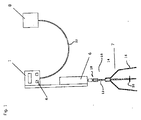
- Figure 1 is a self-leveling screed leveling bracket as a threaded actuator 7 shown, the three angled Contains feet 16, which are arranged on a threaded bearing 14 are.
- a threaded rod 12 runs in the threaded bearing 14, via a drive connection 18 to the servomotor 6 connected is.
- a leveling disc 20 arranged as a reference point for the level is used.
- the servomotor 6 is operated by an electronic measured value recording device 1, as is the case, for example, in DE-GM 296 10 987.9 is described. It contains one water-filled absolute zero sensor 8, e.g. in shape a vessel open to the outside atmosphere, the via a water-filled hose 22 with a in the Measured value detection device 1 arranged differential pressure sensor who is connected to the the differences of the Height readings recorded and the electronic determined in this way Measured values via a processor in control pulses for the Servomotor 6 converts. When you activate the electronic Measured value acquisition device 1 by the button 4 thus the servomotor 6 the leveling disc 20 on the desired level.
- Figure 2 shows a combination of a liquid screed spindle leveling block 7 with a laser measured value acquisition device 2.
- the lower part with the liquid screed spindle leveling block 7 and the actuator 6 corresponds the arrangement of Figure 1.
- the laser data acquisition device 2 receives the emitted by the leveling laser 9 Laser beam 13 and shows the measured height measurements on a visual display or converts it via a processor in control pulses for the servomotor 6 um. With a visual display, the servomotor 6 Use button 11 to move to the desired level.
- FIG. 3 Another possible application is in FIG. 3 shown. It is the use a manual data acquisition device, for example in the form of an optical data acquisition device 3, which are designed as a hose scale can. It contains an absolute zero sensor 9 in the form of an open or closed vessel, the via a hose 22 which is filled with a liquid, for example water, is filled with the manual Measured value acquisition device 3 is connected, the from a riser with graduations can exist. By means of the up-down switching device 5, the servomotor 6 can be controlled.
- the servomotor 6 can be released with the actuator 10 be connected, for example via a pluggable Drive connection 18, including a socket, in which one with the drive axis of the servomotor 6 connected insertion pin is inserted.
- a pluggable Drive connection 18 including a socket, in which one with the drive axis of the servomotor 6 connected insertion pin is inserted.
Landscapes
- Engineering & Computer Science (AREA)
- Physics & Mathematics (AREA)
- General Physics & Mathematics (AREA)
- Architecture (AREA)
- Radar, Positioning & Navigation (AREA)
- Remote Sensing (AREA)
- Civil Engineering (AREA)
- Structural Engineering (AREA)
- Control Of Position Or Direction (AREA)
- Length Measuring Devices By Optical Means (AREA)
Description
Die vorliegende Erfindung betrifft ein für Nivellierung eingerichtetes Gewindestellglied mit in einer Gewindelagerung geführtem Stellglied, an dem ein Stellmotor angeordnet ist, der durch seine Drehbewegung das Stellglied in der Gewindelagerung verstellt, wobei der Stellmotor durch eine Auf-Abwärts-Schalteinrichtung betätigt wird.The present invention relates to a device set up for leveling Threaded actuator with in a threaded bearing guided actuator on which an actuator is arranged, the actuator in the threaded bearing due to its rotary motion adjusted, the servomotor by an up-down switching device is operated.
Solche Stellglieder verden z. B. verwendet, um Höhenniveaus von Fließestrich, Betonkonstruktionen, Hohlraumbodenfüßen oder entsprechenden Deckenkonstruktionen zu nivellieren. Die Nivellierung wurde in herkömmlicher Weise durch manuelle Einstellung des Gewindestellglieds, beispielsweise der Spindelnivellierböcke mit einem konventionellen Nivelliergerät bewirkt. Dabei wurde die Gewindespindel durch Drehen mit der Hand auf das gewünschte Niveau eingestellt, was zeitaufwending und unbequem ist, da die Bedienungsperson sich für jeden Einstellvorgang bücken muß, um an die Gewindespindel zu gelangen. Außerdem ist es möglich, daß beim Ablesen des konventionellen Nivelliergeräts Ablesefehler unterlaufen und das gewünschte Niveau dadurch falsch eingestellt wird. Trotzdem ist diese konventionelle Methode der Niveaueinstellung seit mehr als 20 Jahren unverändert beibehalten worden, weil der Fachmann offenbar eine einfachere und bequemere Methode nicht für durchführbar gehalten hat.Such actuators verden z. B. used to height levels of liquid screed, concrete structures, hollow floor feet or to level the corresponding ceiling constructions. The leveling was done in a conventional manner manual adjustment of the threaded actuator, for example the spindle leveling blocks with a conventional one Leveling device. The threaded spindle was adjusted to the desired level by turning it by hand, which is time consuming and inconvenient because the Operator bend down for each adjustment must to get to the threaded spindle. Besides, is it is possible that when reading the conventional leveling device Reading errors made and the desired level thereby incorrectly set. Still, this is conventional method of level adjustment for more unchanged since 20 years because of the Professional apparently a simpler and more convenient method did not consider feasible.
Die EP 617 945 A2 betrifft ein Gewindestellglied für ein verstellbares Krankenbett mit einem in einer Gewindelagerung geführtem Stellglied.EP 617 945 A2 relates to a threaded actuator for a adjustable hospital bed with one in a threaded position guided actuator.
Die DE 31 43 713 Al betrifft ein entsprechendes Gewindestellglied zum Abstützen und Nivellieren eines Wohnwagens. Keines der Dokumente gibt einen Hinweis darauf, den Stellmotor lösbar mit dem Stellglied zu verbinden. DE 31 43 713 Al relates to a corresponding threaded actuator for supporting and leveling a caravan. None of the documents gives an indication that the servomotor can be released to connect to the actuator.
Aufgabe der vorliegenden Erfindung ist es, ein Gewindestellglied zu schaffen, das die Nachteile der herkömmlichen Stellglieder vermeidet und einfach und ohne Bücken des Bedienungspersonals, also mit ergonomischer Arbeitshaltung, schnell und mit hoher Genauigkeit auf ein gewünschtes Niveau auch mehrerer Spindelnivellierböcke eingestellt werden kann. Dabei soll das Nivellieren der Gewindestellglieder mit allen herkömmlichen Nivelliergeräten möglich sein.The object of the present invention is a threaded actuator to create the disadvantages of the conventional Actuators avoided and simple and without bending over of the operating personnel, i.e. with an ergonomic working posture, quickly and with high accuracy to a desired one Level of several spindle leveling blocks also set can be. The aim is to level the threaded actuators be possible with all conventional leveling devices.
Gelöst wird diese Aufgabe durch ein Gewindestellglied
mit den Merkmalen des kennzeichnenden Teils des Anspruchs 1
. Die abhängigen Ansprüche geben bevorzugte Ausgestaltungen
der Erfindung wieder, insbesondere deren
Kombination mit herkömmlichen Nivelliergeräten.This task is solved by a threaded actuator
with the features of the characterizing part of
Die Erfindung ermöglicht eine schnelle automatische oder manuelle Einstellung des gewünschten Niveaus, eine wesentlich vereinfachte Handhabung und eine sehr genaue Einstellung. Ständiges Bücken und Wiederaufrichten des Bedienungspersonals wird vermieden, wodurch in wesentlich kürzerer Zeit beispielsweise wesentlich mehr Spindelnivellierböcke einivelliert werden können.The invention enables rapid automatic or manual setting of the desired level, an essential simplified handling and a very precise setting. Constant bending down and straightening up Operator is avoided, which is essential less time, for example, significantly more spindle leveling blocks can be leveled.
Das Gewindestellglied enthält ein in einer Gewindelagerung geführtes Stellglied, an welchem ein Stellmotor angeordnet ist, der durch seine Drehbewegung das Stellglied in seiner Gewindelagerung verstellt. Der Stellmotor wird durch eine Auf-Abwärts-Schalteinrichtung betätigt, wodurch das Stellglied in der Gewindelagerung aufwärts bzw. abwärts geführt wird.The threaded actuator contains one in a threaded bearing guided actuator on which an actuator is arranged is the actuator in its by its rotary motion Thread bearing adjusted. The servomotor is replaced by a Up-down switching device actuated, causing the actuator guided upwards or downwards in the thread bearing becomes.
In einer bevorzugten Ausführungsform der Erfindung ist die Auf-Abwärts-Schalteinrichtung mit einer elektronischen Meßwerterfassung-Einrichtung gekoppelt, beispielsweise mit einem elektronischen Schlauchnivelliergerät, wie es z. B. in dem DE-GM 296 01 987.9 beschrieben ist. Auch eine Koppelung mit einem Lasernivelliergerät ist möglich. Dabei können die mit den Geräten elektronisch erfaßten Höhenmeßwerte beispielsweise in einem Prozessor in Steuerimpulse für den Stellmotor umgewandelt werden. Die erfaßten Höhenmeßwerte können aber auch optisch oder akustisch angezeigt und manuell in Steuerimpulse für den Stellmotor umgewandelt werden, beispielsweise über einen Auf-Abwärtsschalter.In a preferred embodiment of the invention Up-down switching device with an electronic Measured value acquisition device coupled, for example with an electronic hose leveler like it e.g. B. is described in DE-GM 296 01 987.9. Also coupling with a laser leveling device is possible. It can be recorded electronically with the devices Height measurements, for example in a processor in control pulses be converted for the servomotor. The captured Altitude measurements can also be visual or acoustic displayed and manually in control pulses for the servomotor be converted, for example via an up-down switch.
Die Erfindung wird nachfolgend anhand der Figurenbeschreibung beispielhaft näher erläutert. Darin zeigen
- Fig. 1
- eine Koppelung eines Fließestrichspindelnivellierbocks mit einem elektronischen Schlauchnivelliergerät;
- Fig. 2
- eine Koppelung des gleichen Nivellierbocks mit einem Laser-Höhenmeßwerterfassungsgerät; und
- Fig. 2
- eine Koppelung des gleichen Nivellierbocks mit einem manuellen Schlauchnivelliergerät.
- Fig. 1
- a coupling of a screed leveling block with an electronic hose leveling device;
- Fig. 2
- a coupling of the same leveling block with a laser height measurement device; and
- Fig. 2
- a coupling of the same leveling block with a manual hose leveling device.
In Figur 1 ist als Gewindestellglied ein Fließestrich-Spindelnivellierbock
7 dargestellt, der drei abgewinkelte
Füße 16 enthält, die an einer Gewindelagerung 14 angeordnet
sind. In der Gewindelagerung 14 läuft eine Gewindestange 12,
die über eine Antriebsverbindung 18 mit dem Stellmotor 6
verbunden ist. Bei einer Drehung des Stellmotors 6 bewegt
sich die Gewindestange 14 in Abhängigkeit von der Drehrichtung
des Stellmotors 6 aufwärts bzw. abwärts. Am
unteren Ende des Gewindestange 12 ist eine Nivellierscheibe
20 angeordnet, die als Bezugspunkt für das
einzunivellierende Niveau dient. In Figure 1 is a self-leveling screed leveling bracket as a threaded
Der Stellmotor 6 wird durch eine elektronische Meßwerterfassungseinrichtung
1 angesteuert, wie sie Z. B. in
dem DE-GM 296 10 987.9 beschrieben ist. Sie enthält einen
wassergefüllten Absolutnullpunktaufnehmer 8, z.B. in Form
eines gegen die äußere Atmosphäre offenen Gefäßes, das
über einen wassergefüllten Schlauch 22 mit einem in der
Meßwerterfassungs-Einrichtung 1 angeordneten Differenzdrucksensor
verbunden ist, der die die Differenzen der
Höhenmeßwerte erfaßt und die so ermittelten elektronischen
Meßwerte über einen Prozessor in Steuerimpulse für den
Stellmotor 6 umwandelt. Beim Aktivieren der elektronischen
Meßwerterfassungs-Einrichtung 1 durch den Taster 4 stellt
somit der Stellmotor 6 die Nivellierscheibe 20 auf das
gewünschte Niveau ein.The
Die Figur 2 stellt eine Kombination eines Fließestrich-Spindelnivellierbocks
7 mit einer Laser-Meßwerterfassungs-Einrichtung
2 dar. Der untere Teil mit dem Fließestrich-Spindelnivellierbock
7 und dem Stellmotor 6 entspricht
der Anordnung der Figur 1. Die Laser-Meßwerterfassungs-Einrichtung
2 empfängt den vom Nivellierlaser 9 ausgesandten
Laserstrahl 13 und zeigt die gemessenen Höhenmeßwerte
auf einer optischen Anzeige an bzw. wandelt sie
über einen Prozessor in Steuerimpulse für den Stellmotor
6 um. Bei optischer Anzeige wird der Stellmotor 6
über den Taster 11 in das gewünschte Niveau verfahren.Figure 2 shows a combination of a liquid screed
Eine weitere Anwendungsmöglichkeit ist in der Figur 3
dargestellt. Es handelt sich dabei um die Verwendung
einer manuellen Meßwerterfassungs-Einrichtung, beispielseise
in Form einer optischen Meßwerterfassungs-Einrichtung
3, die als Schlauchwaage ausgestaltet sein
kann. Sie enthält einen Absolutnullpunktaufnehmer 9
in Form eines offenen oder geschlossenen Gefäßes, der
über einen Schlauch 22, der mit einer Flüssigkeit,
beispielsweise Wasser, gefüllt ist, mit der manuellen
Meßwerterfassungs-Einrichtung 3 verbunden ist, die
aus einem mit Skaleneinteilung versehenen Steigrohr
bestehen kann. Vermittels der Auf-Abwärts-Schalteinrichtung
5 kann mit den beiden Tasten der Stellmotor 6
angesteuert werden.Another possible application is in FIG. 3
shown. It is the use
a manual data acquisition device, for example
in the form of an optical
Der Stellmotor 6 kann mit dem Stellglied 10 lösbar
verbunden sein, beispielsweise über eine steckbare
Antriebsverbindung 18, enthaltend eine Buchse, in
welche ein mit der Antriebsache des Stellmotors 6
verbundener Einsteckdorn eingeführt wird. Auf diese
Weise lassen sich alle oben genannten Meßwerterfassungs-Einrichtungen
mit dem Stellmotor und damit mit dem
Gewindestellglied kombinieren.The
Claims (7)
- Threaded actuator adapted for levelling, comprising an actuator (10) guided in a threaded support, on which a servomotor is disposed that adjusts said actuator (10) in said threaded support (14) by its rotational movement, wherein said actuator (6) is operated by an upward/downward switching means (5), characterised in that
said servomotor (6) is detachably connected to said actuator (10). - Threaded actuator according to Claim 1, characterised in that said upward/downward switching means (5) is coupled to an electronic data detector means (1) for detection of relative elevation values, with said electronically detected relative elevation values being converted in a processor into control pulses for said upward/downward switching means (5).
- Threaded actuator according to Claim 1, characterised in that said upward/downward switching means (5) is coupled to an optical data detector means (3) and that said optically detected relative elevation values are manually or electronically converted into control pulses for said upward/downward switching means (5).
- Threaded actuator according to the preceding Claims, characterised in that it is a flow flooring sighting trestle, a concrete levelling trestle or a threaded actuator for cavity bottom bases or ceiling systems.
- Threaded actuator according to Claim 2, characterised in that said electronic data detector means (1) is an electronic rubber-tube type levelling measuring instrument.
- Threaded actuator according to Claim 2, characterised in that said electronic data detector means is a laser data detector means.
- Threaded actuator according to Claim 3, characterised in that said optical data detector means (3) is a rubber-tube type levelling measuring instrument.
Applications Claiming Priority (4)
| Application Number | Priority Date | Filing Date | Title |
|---|---|---|---|
| DE29601987U DE29601987U1 (en) | 1996-02-06 | 1996-02-06 | Electronic hose level measuring device |
| DE29601987U | 1996-05-21 | ||
| DE29609271U DE29609271U1 (en) | 1996-05-23 | 1996-05-23 | Motor-controlled height adjustment device for screed leveling jacks |
| DE29609271U | 1996-05-23 |
Publications (3)
| Publication Number | Publication Date |
|---|---|
| EP0809166A2 EP0809166A2 (en) | 1997-11-26 |
| EP0809166A3 EP0809166A3 (en) | 1998-05-13 |
| EP0809166B1 true EP0809166B1 (en) | 2001-09-12 |
Family
ID=26058619
Family Applications (1)
| Application Number | Title | Priority Date | Filing Date |
|---|---|---|---|
| EP19970710010 Expired - Lifetime EP0809166B1 (en) | 1996-02-06 | 1997-05-21 | Spindle driven servomechanism |
Country Status (1)
| Country | Link |
|---|---|
| EP (1) | EP0809166B1 (en) |
Families Citing this family (1)
| Publication number | Priority date | Publication date | Assignee | Title |
|---|---|---|---|---|
| GB2469031B (en) * | 2009-03-30 | 2013-09-11 | Deer Park Engineering Ltd | Building construction device |
Family Cites Families (6)
| Publication number | Priority date | Publication date | Assignee | Title |
|---|---|---|---|---|
| DE3143713A1 (en) * | 1981-11-04 | 1983-05-11 | Wolfgang 6380 Bad Homburg Nesselberger | Device for supporting and levelling a caravan or the like |
| DE3713006A1 (en) * | 1987-04-16 | 1988-10-27 | Hydro Geraetebau Gmbh & Co Kg | Equipment for jacking up vehicles |
| US4993161A (en) * | 1990-01-04 | 1991-02-19 | David White, Inc. | Laser beam level instrument |
| DE4310003C1 (en) * | 1993-03-27 | 1994-06-01 | Medical Objekteinrichtung Gmbh | Hospital bed lifting frame - has frame with narrow side head and foot parts, having lying frame located in frame and lifting frame under bed frame with electro-mechanical or hydraulic height adjustment and movement castors |
| DE29601987U1 (en) * | 1996-02-06 | 1996-03-28 | Straub, Wolfgang, 63877 Sailauf | Electronic hose level measuring device |
| DE19626770C1 (en) * | 1996-07-03 | 1998-03-26 | Martin Theodor Melchior | Leveling stand |
-
1997
- 1997-05-21 EP EP19970710010 patent/EP0809166B1/en not_active Expired - Lifetime
Also Published As
| Publication number | Publication date |
|---|---|
| EP0809166A3 (en) | 1998-05-13 |
| EP0809166A2 (en) | 1997-11-26 |
Similar Documents
| Publication | Publication Date | Title |
|---|---|---|
| DE3838512C1 (en) | ||
| DE4002493C2 (en) | ||
| DE102010004517B4 (en) | Optical instrument with angle display and method of operating the same | |
| DE3827458C2 (en) | ||
| DE102009042123B3 (en) | Geodetic instrument and method for this | |
| DE10102171B4 (en) | Longitudinal Linearity Compensation Method and Rotational Accuracy Compensation Method of a Meter | |
| WO1991011684A9 (en) | CLINOMETER | |
| DE19534535A1 (en) | Coordinate measuring machine | |
| DE69927597T2 (en) | Method and device for folding angle measurement of a sheet in a folding machine | |
| DE2821112A1 (en) | METHOD AND DEVICE FOR MACHINE ADJUSTMENT OF THE INCLINATION OF A ROCK DRILLING DEVICE | |
| DE3833203C1 (en) | Device for the numeric acquisition of coordinates for CAD systems | |
| DE19501094A1 (en) | Calibrating moving appts. e.g. industrial robot or medical manipulator | |
| DD294337A5 (en) | MEASURING DEVICE | |
| EP0809166A2 (en) | Spindle driven servomechanism | |
| EP2181304A1 (en) | Pendulum laser device | |
| DE102020006290A1 (en) | Adapter for a support member of a surveying instrument and method | |
| DE19814149C2 (en) | Two-axis laser measuring device and combination of the same with a measuring instrument | |
| DE4443343A1 (en) | Electronic safety-check for scaffolding erection | |
| LU102766B1 (en) | Fastening device for positioning an optical measuring and/or marking instrument | |
| DE9007731U1 (en) | Measuring device for determining the position of opto-electronically representable spatial points | |
| DE9100510U1 (en) | Angle straightedge | |
| CH680621A5 (en) | Measuring system for shaft or drainage channel condition - uses computer-controlled measuring head to scan inside surface of shaft or channel with monitor display | |
| DE3413796C2 (en) | ||
| DE29914297U1 (en) | Laser beam leveling device | |
| DE29600712U1 (en) | Laser addition to an existing optical leveling device |
Legal Events
| Date | Code | Title | Description |
|---|---|---|---|
| PUAI | Public reference made under article 153(3) epc to a published international application that has entered the european phase |
Free format text: ORIGINAL CODE: 0009012 |
|
| AK | Designated contracting states |
Kind code of ref document: A2 Designated state(s): AT BE CH DE DK ES FI FR GB GR IE IT LI LU MC NL PT SE |
|
| PUAL | Search report despatched |
Free format text: ORIGINAL CODE: 0009013 |
|
| AK | Designated contracting states |
Kind code of ref document: A3 Designated state(s): AT BE CH DE DK ES FI FR GB GR IE IT LI LU MC NL PT SE |
|
| 17P | Request for examination filed |
Effective date: 19980921 |
|
| 17Q | First examination report despatched |
Effective date: 20000331 |
|
| GRAG | Despatch of communication of intention to grant |
Free format text: ORIGINAL CODE: EPIDOS AGRA |
|
| GRAG | Despatch of communication of intention to grant |
Free format text: ORIGINAL CODE: EPIDOS AGRA |
|
| GRAH | Despatch of communication of intention to grant a patent |
Free format text: ORIGINAL CODE: EPIDOS IGRA |
|
| GRAH | Despatch of communication of intention to grant a patent |
Free format text: ORIGINAL CODE: EPIDOS IGRA |
|
| GRAA | (expected) grant |
Free format text: ORIGINAL CODE: 0009210 |
|
| AK | Designated contracting states |
Kind code of ref document: B1 Designated state(s): AT BE CH DE DK ES FI FR GB GR IE IT LI LU MC NL PT SE |
|
| PG25 | Lapsed in a contracting state [announced via postgrant information from national office to epo] |
Ref country code: NL Free format text: LAPSE BECAUSE OF FAILURE TO SUBMIT A TRANSLATION OF THE DESCRIPTION OR TO PAY THE FEE WITHIN THE PRESCRIBED TIME-LIMIT Effective date: 20010912 Ref country code: IT Free format text: LAPSE BECAUSE OF FAILURE TO SUBMIT A TRANSLATION OF THE DESCRIPTION OR TO PAY THE FEE WITHIN THE PRESCRIBED TIME-LIMIT;WARNING: LAPSES OF ITALIAN PATENTS WITH EFFECTIVE DATE BEFORE 2007 MAY HAVE OCCURRED AT ANY TIME BEFORE 2007. THE CORRECT EFFECTIVE DATE MAY BE DIFFERENT FROM THE ONE RECORDED. Effective date: 20010912 Ref country code: IE Free format text: LAPSE BECAUSE OF FAILURE TO SUBMIT A TRANSLATION OF THE DESCRIPTION OR TO PAY THE FEE WITHIN THE PRESCRIBED TIME-LIMIT Effective date: 20010912 Ref country code: GB Free format text: LAPSE BECAUSE OF FAILURE TO SUBMIT A TRANSLATION OF THE DESCRIPTION OR TO PAY THE FEE WITHIN THE PRESCRIBED TIME-LIMIT Effective date: 20010912 Ref country code: FR Free format text: LAPSE BECAUSE OF FAILURE TO SUBMIT A TRANSLATION OF THE DESCRIPTION OR TO PAY THE FEE WITHIN THE PRESCRIBED TIME-LIMIT Effective date: 20010912 Ref country code: FI Free format text: LAPSE BECAUSE OF FAILURE TO SUBMIT A TRANSLATION OF THE DESCRIPTION OR TO PAY THE FEE WITHIN THE PRESCRIBED TIME-LIMIT Effective date: 20010912 |
|
| REF | Corresponds to: |
Ref document number: 205610 Country of ref document: AT Date of ref document: 20010915 Kind code of ref document: T |
|
| REG | Reference to a national code |
Ref country code: CH Ref legal event code: EP |
|
| REG | Reference to a national code |
Ref country code: IE Ref legal event code: FG4D Free format text: GERMAN |
|
| REF | Corresponds to: |
Ref document number: 59704574 Country of ref document: DE Date of ref document: 20011018 |
|
| PG25 | Lapsed in a contracting state [announced via postgrant information from national office to epo] |
Ref country code: SE Free format text: LAPSE BECAUSE OF FAILURE TO SUBMIT A TRANSLATION OF THE DESCRIPTION OR TO PAY THE FEE WITHIN THE PRESCRIBED TIME-LIMIT Effective date: 20011212 Ref country code: PT Free format text: LAPSE BECAUSE OF FAILURE TO SUBMIT A TRANSLATION OF THE DESCRIPTION OR TO PAY THE FEE WITHIN THE PRESCRIBED TIME-LIMIT Effective date: 20011212 Ref country code: DK Free format text: LAPSE BECAUSE OF FAILURE TO SUBMIT A TRANSLATION OF THE DESCRIPTION OR TO PAY THE FEE WITHIN THE PRESCRIBED TIME-LIMIT Effective date: 20011212 |
|
| PG25 | Lapsed in a contracting state [announced via postgrant information from national office to epo] |
Ref country code: GR Free format text: LAPSE BECAUSE OF FAILURE TO SUBMIT A TRANSLATION OF THE DESCRIPTION OR TO PAY THE FEE WITHIN THE PRESCRIBED TIME-LIMIT Effective date: 20011214 |
|
| NLV1 | Nl: lapsed or annulled due to failure to fulfill the requirements of art. 29p and 29m of the patents act | ||
| GBV | Gb: ep patent (uk) treated as always having been void in accordance with gb section 77(7)/1977 [no translation filed] |
Effective date: 20010912 |
|
| PG25 | Lapsed in a contracting state [announced via postgrant information from national office to epo] |
Ref country code: ES Free format text: LAPSE BECAUSE OF FAILURE TO SUBMIT A TRANSLATION OF THE DESCRIPTION OR TO PAY THE FEE WITHIN THE PRESCRIBED TIME-LIMIT Effective date: 20020326 |
|
| PG25 | Lapsed in a contracting state [announced via postgrant information from national office to epo] |
Ref country code: MC Free format text: LAPSE BECAUSE OF NON-PAYMENT OF DUE FEES Effective date: 20020521 Ref country code: LU Free format text: LAPSE BECAUSE OF NON-PAYMENT OF DUE FEES Effective date: 20020521 Ref country code: AT Free format text: LAPSE BECAUSE OF NON-PAYMENT OF DUE FEES Effective date: 20020521 |
|
| REG | Reference to a national code |
Ref country code: IE Ref legal event code: FD4D |
|
| PG25 | Lapsed in a contracting state [announced via postgrant information from national office to epo] |
Ref country code: LI Free format text: LAPSE BECAUSE OF NON-PAYMENT OF DUE FEES Effective date: 20020531 Ref country code: CH Free format text: LAPSE BECAUSE OF NON-PAYMENT OF DUE FEES Effective date: 20020531 Ref country code: BE Free format text: LAPSE BECAUSE OF NON-PAYMENT OF DUE FEES Effective date: 20020531 |
|
| PLBE | No opposition filed within time limit |
Free format text: ORIGINAL CODE: 0009261 |
|
| STAA | Information on the status of an ep patent application or granted ep patent |
Free format text: STATUS: NO OPPOSITION FILED WITHIN TIME LIMIT |
|
| EN | Fr: translation not filed | ||
| 26N | No opposition filed | ||
| REG | Reference to a national code |
Ref country code: CH Ref legal event code: PL |
|
| PGFP | Annual fee paid to national office [announced via postgrant information from national office to epo] |
Ref country code: DE Payment date: 20070725 Year of fee payment: 11 |
|
| PG25 | Lapsed in a contracting state [announced via postgrant information from national office to epo] |
Ref country code: DE Free format text: LAPSE BECAUSE OF NON-PAYMENT OF DUE FEES Effective date: 20081202 |