EP3614012B1 - Schwingplattenanordnung zum verbinden einer maschine mit einem fundament - Google Patents
Schwingplattenanordnung zum verbinden einer maschine mit einem fundament Download PDFInfo
- Publication number
- EP3614012B1 EP3614012B1 EP19190735.1A EP19190735A EP3614012B1 EP 3614012 B1 EP3614012 B1 EP 3614012B1 EP 19190735 A EP19190735 A EP 19190735A EP 3614012 B1 EP3614012 B1 EP 3614012B1
- Authority
- EP
- European Patent Office
- Prior art keywords
- base plate
- plate assembly
- plate
- oscillating
- machine
- Prior art date
- Legal status (The legal status is an assumption and is not a legal conclusion. Google has not performed a legal analysis and makes no representation as to the accuracy of the status listed.)
- Active
Links
Images


Classifications
-
- F—MECHANICAL ENGINEERING; LIGHTING; HEATING; WEAPONS; BLASTING
- F16—ENGINEERING ELEMENTS AND UNITS; GENERAL MEASURES FOR PRODUCING AND MAINTAINING EFFECTIVE FUNCTIONING OF MACHINES OR INSTALLATIONS; THERMAL INSULATION IN GENERAL
- F16F—SPRINGS; SHOCK-ABSORBERS; MEANS FOR DAMPING VIBRATION
- F16F7/00—Vibration-dampers; Shock-absorbers
- F16F7/12—Vibration-dampers; Shock-absorbers using plastic deformation of members
-
- F—MECHANICAL ENGINEERING; LIGHTING; HEATING; WEAPONS; BLASTING
- F16—ENGINEERING ELEMENTS AND UNITS; GENERAL MEASURES FOR PRODUCING AND MAINTAINING EFFECTIVE FUNCTIONING OF MACHINES OR INSTALLATIONS; THERMAL INSULATION IN GENERAL
- F16F—SPRINGS; SHOCK-ABSORBERS; MEANS FOR DAMPING VIBRATION
- F16F15/00—Suppression of vibrations in systems; Means or arrangements for avoiding or reducing out-of-balance forces, e.g. due to motion
- F16F15/02—Suppression of vibrations of non-rotating, e.g. reciprocating systems; Suppression of vibrations of rotating systems by use of members not moving with the rotating systems
- F16F15/022—Suppression of vibrations of non-rotating, e.g. reciprocating systems; Suppression of vibrations of rotating systems by use of members not moving with the rotating systems using dampers and springs in combination
-
- F—MECHANICAL ENGINEERING; LIGHTING; HEATING; WEAPONS; BLASTING
- F16—ENGINEERING ELEMENTS AND UNITS; GENERAL MEASURES FOR PRODUCING AND MAINTAINING EFFECTIVE FUNCTIONING OF MACHINES OR INSTALLATIONS; THERMAL INSULATION IN GENERAL
- F16F—SPRINGS; SHOCK-ABSORBERS; MEANS FOR DAMPING VIBRATION
- F16F9/00—Springs, vibration-dampers, shock-absorbers, or similarly-constructed movement-dampers using a fluid or the equivalent as damping medium
- F16F9/30—Springs, vibration-dampers, shock-absorbers, or similarly-constructed movement-dampers using a fluid or the equivalent as damping medium with solid or semi-solid material, e.g. pasty masses, as damping medium
- F16F9/306—Springs, vibration-dampers, shock-absorbers, or similarly-constructed movement-dampers using a fluid or the equivalent as damping medium with solid or semi-solid material, e.g. pasty masses, as damping medium of the constrained layer type, i.e. comprising one or more constrained viscoelastic layers
Definitions
- a vibrating plate arrangement for connecting a machine to a foundation is already known.
- a vibration plate arrangement comprises at least a first vibration damper, a base plate and at least one second vibration damper, the base plate being connected to the foundation with the first vibration damper being interposed, and the base plate being connected to the machine with the second vibration damper being interposed.
- the EP 1 887 124 A1 discloses a floor-stabilizing foot for a household appliance with a base and a bolt, at least one damping film made of viscoelastic material being arranged between the base and the bolt.
- the invention is based on an oscillating plate arrangement for connecting a machine to a foundation, comprising at least a first vibration damper, a base plate arrangement and at least one second vibration damper, the base plate arrangement being connectable to the foundation with the at least one first vibration damper being interposed, and the base plate arrangement being Interposition of the at least one second vibration damper can be connected to the machine.
- the floor panel arrangement comprises a first floor panel, at least one vibration-damping and/or isolating intermediate panel and at least one further floor panel.
- the first base plate, the at least one intermediate plate and/or the at least one further base plate each have an essentially plate-like shape, each with two essentially parallel main surfaces.
- An oscillating plate arrangement is proposed in which the first base plate is connected, in particular welded, to at least one, preferably three, bolts standing perpendicularly on a second main surface of the first base plate, and that the first base plate, with the at least one intermediate plate interposed, the at least one another base plate and the at least one, preferably three, second vibration damper can be connected, in particular screwed, to a machine by means of the bolt.
- This provides a possibility for stable spatial fixing of the machine on the floor plate arrangement with good vibration damping at the same time.
- the foundation which is in particular stationary, is a load-bearing structure such as a concrete foundation, a machine foundation, a fixed frame or a fixed housing and serves as the installation site or as the installation area for the machine including the vibrating plate arrangement.
- the machine for example a production machine, a turbomachine or a displacement machine, fulfills a purpose desired by a user during operation.
- undesirable mechanical oscillations can also occur, such as vibrations, shocks or impacts.
- vibrations can be caused by repetitively moving, in particular rotating machine parts, shocks can be caused by a starting torque of the machine when starting machine operation.
- vibrations are torsional vibrations about an axis, transverse vibrations perpendicular to a plane, longitudinal vibrations in a plane.
- the oscillating plate arrangement is spatially between the foundation and the machine can be arranged or arranged.
- the oscillating plate arrangement serves to dampen and isolate (decouple) vibrations and to absorb vibration energy from the foundation. The movement and the energy of the vibrations of the machine do not reach or at least reduce the foundation.
- the oscillating plate arrangement comprises one or more first vibration dampers for vibration-damped and vibration-energy-absorbing connection to the foundation on the one hand and one or more second vibration dampers for vibration-damped and vibration-energy-absorbing connection with the machine on the other hand.
- the vibration dampers can comprise an elastomer, in particular rubber.
- the vibration dampers can include a metal spring, for example a helical spring, a plate spring or a leaf spring.
- the vibration dampers can include a hydraulic or pneumatic spring. Vibration dampers are used to dampen unwanted mechanical vibrations. Between and connected to the first vibration isolators and the second vibration isolators is the floor panel assembly.
- the at least one first vibration damper is placed between the base plate arrangement and the foundation, ie arranged, in particular connected to the base plate arrangement and/or connectable to the foundation.
- the at least one second vibration damper is placed between the floor panel arrangement and the machine, ie arranged, in particular connected to the floor panel arrangement and/or connectable to the machine.
- the floor panel assembly includes a first floor panel, at least one intermediate panel, and at least one additional floor panel.
- the floor panel arrangement is constructed according to the sandwich principle and comprises the first floor panel, the intermediate panel and the further floor panel in a spatial sequence.
- the floor panel arrangement comprises the first floor panel, a first intermediate panel, a first additional floor panel, a second intermediate panel, a second additional floor panel in a spatial sequence.
- the intermediate plate dampens and/or isolates vibrations of the further base plate from the first base plate and absorbs the vibration energy. the Movement and the energy of the vibrations of the further base plate do not reach or at least reduce the first base plate.
- a plate-like shape is understood here as a flat, planar geometry of a body (in particular the first base plate, the intermediate plate, the further base plate), the thickness of which is small compared to its width and length or compared to its diameter.
- the width and length or the diameter characterize the two parallel main surfaces of a body, which can be angular or round.
- a first base plate, an intermediate plate and/or a further base plate with a plate-like shape can be produced particularly inexpensively, for example from a plate-shaped semi-finished product.
- the main surfaces of the bodies can be the same size. They can also be of different sizes.
- first floor panel is connected, in particular welded, to at least one, preferably three, bolts perpendicular to the second main surface of the first floor panel, and that the first floor panel with the interposition of the at least one intermediate panel, the at least one further floor panel and the at least one, preferably three, second vibration dampers can be connected, in particular screwed, to a machine by means of the bolt, there is a possibility of stable spatial fixing of the machine on the base plate arrangement with good vibration damping at the same time.
- an advantageous exemplary embodiment of the oscillating plate arrangement is characterized in that the at least one intermediate plate has elastic or viscoelastic properties, preferably an elastic or viscoelastic material, in particular at least one material from the material groups bitumen, elastomers, silicone. With low material and manufacturing costs, these properties and materials are particularly well suited for vibration damping and vibration energy absorption. It has been shown that an elastic or viscoelastic intermediate plate ensures particularly good vibration damping.
- a further advantageous exemplary embodiment of the oscillating plate arrangement is characterized in that the first base plate and/or the at least one further base plate comprise at least one metal, preferably made of a metal, in particular iron or steel. These properties and materials are particularly well suited for vibration damping and vibration damping with low material and production costs and due to their strength and density.
- a further advantageous exemplary embodiment of the oscillating plate arrangement is characterized in that the first base plate, the at least one intermediate plate and/or the at least one further base plate each have a shape that deviates from a plate-like shape.
- a plate-like shape can be deformed at the edges, in particular bent once or twice.
- Another shape can be deep drawn.
- Yet another shape may have ribs for mechanical reinforcement.
- a further advantageous exemplary embodiment of the oscillating plate arrangement is characterized in that the oscillating plate arrangement is designed to withstand torsional vibrations acting on it, in particular about a longitudinal axis perpendicular to the main surfaces, as well as transverse vibrations, in particular perpendicular to the main surfaces, and longitudinal vibrations, in particular in the plane of the main surfaces dampen
- a further advantageous exemplary embodiment of the oscillating plate arrangement is characterized in that the base plate arrangement is designed to dampen torsional vibrations acting on it, in particular about a longitudinal axis perpendicular to the main surfaces, and transverse vibrations, in particular perpendicular to the main surfaces.
- the floor panel arrangement thus has particularly good properties for damping twisting and bending. These properties are set by the selected geometric dimensions and the selected material, in particular the intermediate plate.
- a further advantageous exemplary embodiment of the oscillating plate arrangement is characterized in that the intermediate plate is connected, in particular glued, with its first main surface to a second main surface of the first base plate, and/or that the intermediate plate is flat with its second main surface to a first main surface of the other base plate connected, especially glued, is.
- the first base plate, the intermediate plate and/or the further base plate can be glued to one another and forces can be transmitted by bonding.
- the first base plate, the intermediate plate and/or the further base plate can also be pressed onto one another and forces can be transmitted by adhesion.
- a further advantageous exemplary embodiment of the oscillating plate arrangement is characterized in that at least the main surfaces of the intermediate plate (in particular its second main surface) and the main surfaces of the further base plate (in particular its first main surface) have essentially the same dimensions.
- the first base plate which can be assumed to be larger than the intermediate plate and the further base plate, this entails a relatively smaller vibratory movement of the further base plate, in particular in the plane of the main surfaces, but also perpendicular to the main surfaces.
- An alternative advantageous embodiment of the oscillating plate arrangement is characterized in that the main surfaces of the intermediate plate (in particular its second main surface) have smaller dimensions than the main surfaces of the further base plate (in particular its first main surface).
- the first base plate which can be assumed to be larger than the intermediate plate and the further base plate, this is accompanied by a relatively greater vibrational movement of the further base plate, in particular in the plane of the main surfaces, but also perpendicular to the main surfaces.
- a further advantageous exemplary embodiment of the oscillating plate arrangement is characterized in that the main surfaces of the first base plate, the at least one intermediate plate and/or the at least one further base plate are essentially parallel to a first connection level for connecting the oscillating plate arrangement to the foundation and/or parallel to a second Connection level for connecting the oscillating plate assembly are arranged with the machine, wherein the connection levels of the at least one first vibration damper and / or of the at least one second vibration damper is formed.
- the first connection level is formed in particular by ends of the first vibration dampers, which are located on a side of the first vibration dampers facing away from the first base plate.
- the second connection level is formed in particular by ends of the second vibration dampers, which lie on a side of the second vibration dampers that faces away from the further base plate.
- the parallel arrangement results in good damping properties, a high number of identical parts and a lightweight design of the vibration dampers.
- a further advantageous exemplary embodiment of the oscillating plate arrangement is characterized in that the first base plate is connected to four first vibration dampers arranged in the edge area of the first main surface of the first base plate. This provides a possibility for stable, in particular tilting-resistant, spatial fixing of the base plate arrangement on the foundation with good vibration damping at the same time.
- a further advantageous exemplary embodiment of the oscillating plate arrangement is characterized in that the first base plate is stepped in the area of two opposite edges and in each area a first step section which is angled essentially perpendicularly to the main surfaces of the first base plate and has a height H and an essentially parallel to has the main surfaces of the first floor plate running, from the first step section, in particular outwards, angled second step section.
- the second stage section is connected to the at least one first vibration damper. Due to the gradual offset of the height H between the main surface and the second step section, even with higher or larger first Vibration dampers a particularly low, so space-saving height of the oscillating plate assembly can be achieved.
- the step portions stiffen the first floor panel.
- a further advantageous exemplary embodiment of the oscillating plate arrangement is characterized in that the first base plate has angled sections in the area of two opposite edges which are not in the stepped areas, preferably essentially perpendicular to the main surfaces. For example, these sections may be directed in opposite directions to the first step sections. The sections stiffen the first floor panel.
- a machine arrangement for connecting a machine to a foundation comprising a machine and an oscillating plate arrangement, the machine being connected to the oscillating plate arrangement and the oscillating plate arrangement being connectable to the foundation.
- This Machine arrangement is characterized in that the oscillating plate arrangement is designed according to one of the above statements. This results in a machine arrangement that introduces undesired vibrations of the machine into the oscillating plate arrangement and the foundation in a well-damped manner.
- a compressor arrangement for connecting a compressor, in particular a compressor for driving a heat pump or a refrigeration unit, to a compressor housing, comprising a compressor, an oscillating plate arrangement and a compressor housing, the compressor being connected to the oscillating plate arrangement, and the oscillating plate arrangement being connected to the Compressor housing is connected.
- the compressor arrangement is characterized in that the oscillating plate arrangement is designed according to one of the above statements.
- the compressor is a special version of the machine.
- the compressor housing is a special version of the foundation for the compressor. Instead of a compressor housing, a heat pump housing, a refrigeration unit housing or a frame can also be used as the foundation. This results in a compressor arrangement that introduces undesired vibrations of the compressor into the oscillating plate arrangement and the compressor housing in a well-damped manner.
- Out of figure 1 shows an exploded view of a vibrating plate assembly 10 for connecting a machine (not shown) to a foundation (not shown).
- Out of figure 2 follows the assembled oscillating plate arrangement figure 1 out.
- the vibration plate assembly 10 includes four first vibration dampers 11 (three visible, one invisible behind the first floor panel), a floor panel arrangement 20 and three second vibration dampers 12.
- the floor panel arrangement 20 comprises a first floor panel 30, an intermediate panel 40 and a further floor panel 50.
- the intermediate plate 40 is hidden between the first base plate 30 and the further base plate 50 and is not visible due to the selected perspective.
- the base plate arrangement 20 can be connected to the foundation with the four first vibration dampers 11 being interposed.
- the first connection level 60 is indicated, at which the first vibration damper 11 and the foundation touch and are connected to one another, in particular screwed.
- the floor pan assembly 20 is connectable to the machine with the interposition of the three second vibration isolators 12 .
- the intermediate plate 40 is designed to dampen and/or isolate vibrations.
- the intermediate plate 40 preferably has elastic or viscoelastic properties, for example it is made of an elastic or viscoelastic material, in particular bitumen.
- the first base plate 30 and/or the further base plate 50 are designed to divert and eliminate vibrations.
- the first floor panel 30 and/or the further floor panel 50 preferably have rigid and/or heavy properties, for example they are made of a rigid and/or heavy material, in particular a metal, in particular iron or steel.
- the first base plate 30, the intermediate plate 40 and the further base plate 50 each have a plate-like shape, each with two parallel main surfaces (31, 32, 41, 42, 51, 52).
- the main surfaces of the first base plate 30, the intermediate plate 40 and the further base plate 50 each have an essentially rectangular shape.
- the main surfaces of the first base plate 30, the intermediate plate 40 and/or the further base plate 50 can also have a shape that deviates from the rectangular shape, for example a triangular, a hexagonal or a round shape.
- first vibration damper 11, first base plate 30, intermediate plate 40, further base plate 50 and second vibration damper 12 makes the oscillating plate arrangement 10 particularly suitable for torsional vibrations acting on it around one of the main surfaces to dampen and isolate the vertical longitudinal axis, transverse vibrations perpendicular to the main surfaces, and longitudinal vibrations in the plane of the main surfaces.
- vibrations of small amplitudes and higher frequencies cannot penetrate the floor panel assembly 20, but are at least partially reflected on the first floor panel 30 and the further floor panel 50, at least partially damped and isolated in the intermediate panel 40, and at least partially eliminated by the entirety of the floor panel assembly 20 .
- the eradication is supported by the first vibration damper 11 and the second vibration damper 12 .
- the intermediate plate 40 is connected, in particular glued, with its first main surface 41 to the second main surface 32 of the first base plate 30 . Furthermore, the intermediate plate 40 is connected, in particular glued, with its second main surface 42 to the first main surface 51 of the further base plate 50 .
- the first base plate 30 and the further base plate 50 are separated from one another by means of the intermediate plate 40 and have no rigid connection, for example metal to metal.
- the flat connections bring about effective vibration damping over the entire intermediate plate 40, without individual areas being more or less stressed. Bonding is particularly well suited to creating a surface connection.
- the main surfaces of the first floor panel 30, the intermediate panel 40 and the further floor panel 50 have essentially the same dimensions.
- the largest possible connecting surfaces are provided between the panels and, purely in terms of dimensions, the largest possible vibration damping.
- the main surfaces of the first base plate 30, the intermediate plate 40 and the further base plate 50 are arranged parallel to the first connection plane 60 for connecting the oscillating plate arrangement 10 to the foundation.
- the main surfaces of the first base plate, the intermediate plate and the further base plate are arranged parallel to a second connection plane 70 for connecting the oscillating plate arrangement 10 to the machine.
- the second connection level 70 is formed by the three second vibration dampers 12 .
- the second connection plane 70 is formed in particular by ends 121 of the second vibration dampers 12 which lie on a side of the second vibration dampers 12 which faces away from the further base plate 50 .
- the second vibration dampers 12 have connection points or connection surfaces 121 for connection to and support on the machine; these connection points or connection surfaces 121 define the second connection level 70.
- the parallel arrangement results in good damping properties, a greater use of identical parts and a lightweight design for the vibration dampers 11, 12
- the first base plate 30 is connected, preferably welded, to three bolts 33 standing perpendicularly on the second main surface 32 of the first base plate 30 .
- the first base plate 30 can be connected to the machine by means of the bolts 33, in particular screwed.
- the machine is supported on the further base plate 50 in a vibration-damped manner by means of the three second vibration dampers 12 .
- the further base plate 50 is supported on the first base plate 30 by means of the intermediate plate 40 in a vibration-damped manner. A vibration-damping and at the same time sufficiently fixing possibility of connecting the machine to the base plate arrangement 20 is thus provided.
- the first floor panel 30 is connected to four first vibration dampers 11 arranged in the edge region of the first main surface 31 of the first floor panel 30 .
- the first vibration dampers 11 are therefore arranged on the side 31 of the first base plate 30 facing away from the machine. This results in a vibration-damping and at the same time sufficiently fixing option for connecting the base plate arrangement 20 to the foundation.
- the damped vibration which is introduced into the further base plate 50 via the three second vibration dampers 12, generates characteristic vibration modes in the further base plate 50 due to the three connection points 122.
- the vibration of the first base plate 30, further damped by the intermediate plate 40 has due to the four connection points 112 of the four first vibration dampers 11 to the foundation completely different vibration modes. These different modes of vibration at least partially cancel each other out in the base plate arrangement 20, in particular in the intermediate plate 40.
- the oscillating plate arrangement 10 results in a vibration-damping and at the same time sufficiently fixing possibility of connecting the machine to the foundation.
- the sandwich structure of the base plate arrangement 20 with the first base plate 30, intermediate plate 40 and further base plate 50 is particularly vibration-damping in a vibration range due to the combination of its individual properties of strength and mass as well as elasticity or viscoelasticity together with the respective, different number of connection points 112, 122. which effectively supplements the damping properties of the first vibration damper 11 and the second vibration damper 12 .
- the first base plate 30 is reshaped at the edges, in particular bent once or twice.
- the first base plate 30 is doubly angled in the area of two opposite edges and has a step-like design.
- the first base plate 30 has a first step section 34 with a height H, which is angled essentially perpendicularly to the main surfaces 31, 32, and a second step section which runs essentially parallel to the main surfaces 31, 32 and is angled from the first step section 34 35.
- the two second step sections 35 are each connected to two of the four first vibration dampers 11.
- the overall height of the base plate arrangement 20 above the foundation can be significantly reduced in spite of the overall height of the vibration dampers 11. This has special advantages in tight installation situations.
- the overall height of the floor panel arrangement 20 is reduced by the amount H.
- the first base plate 30 is angled in sections in the area of two opposite edges, which are not the stepped areas, preferably essentially perpendicular to the main surfaces. These angled sections 36 can be directed in the opposite direction to the first step sections 34, for example.
- the step sections 34, 35 and sections 36 stiffen the first floor panel.
- the geometry of the first base plate 30 is relatively complex; it can be formed more easily, for example, from a rather thin material such as thin sheet metal.
- the geometry of the additional base plate 50 is very simple; it can also easily be formed from a thicker material, such as a thicker sheet metal.
- a total mass of the first base plate 30, intermediate plate 40 and further base plate 50, which influences the damping and absorbing properties of the base plate arrangement 20, can thus advantageously be adjusted independently of the geometry of the first base plate 30 by means of a thickness of the further base plate 50.
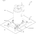
- FIG 3 shows a compressor assembly 100 in an exploded view
- figure 4 shows the same compressor assembly 100 in assembled condition.
- the compressor arrangement 100 is used to connect a compressor 200, in particular a compressor 200 for driving a heat pump or a refrigeration unit, to a compressor housing, of which only the connection plane 60 is shown here.
- the compressor arrangement 100 comprises a compressor 200, an oscillating plate arrangement 10 and a compressor housing (connection level 60), the compressor 200 being connected to the oscillating plate arrangement 10, and the oscillating plate arrangement 10 being connected to the compressor housing (connection level 60).
- the oscillating plate arrangement 10 can be designed as described above.
- the swing plate assembly 10 includes four first vibration dampers 11, a floor plate assembly 20 and three second vibration dampers 12.
- the floor plate assembly 20 includes a first Base plate 30, a vibration-damping and/or isolating intermediate plate 40 and another base plate 50.
- connection level 60 and the second connection level 70 can be seen, formed by connection points or connection surfaces of the vibration dampers 11, 12, for connection to and support on the compressor housing (connection level 60) on the one hand and the compressor 200 on the other.
- the oscillating plate arrangement 10 is particularly suitable for installing a compressor 200 in a housing (connection level 60) or frame of the compressor 200 or the heat pump or the refrigeration unit in a vibration-damped and at least partially vibration-isolating manner.
- Undesirable oscillations of the compressor 200 such as vibrations, shocks or impacts of the most varied of forms and modes are effectively dampened and isolated.
- vibrations that potentially affect components, in particular components that destroy them, but also tactile and audible vibrations are kept away from the housing (connection level 60) or frame and any other components arranged therein.
- there is a quiet, quiet, stable and safe compressor operation which creates the best conditions with regard to a long product life and with regard to the acoustic and/or haptic or tactile comfort and the health of a user.
Landscapes
- Engineering & Computer Science (AREA)
- General Engineering & Computer Science (AREA)
- Mechanical Engineering (AREA)
- Physics & Mathematics (AREA)
- Acoustics & Sound (AREA)
- Aviation & Aerospace Engineering (AREA)
- Vibration Prevention Devices (AREA)
Description
- Es ist bereits eine Schwingplattenanordnung zum Verbinden einer Maschine mit einem Fundament bekannt. In der Regel umfasst eine solche Schwingplattenanordnung mindestens einen ersten Schwingungsdämpfer, eine Bodenplatte und mindestens einen zweiten Schwingungsdämpfer, wobei die Bodenplatte unter Zwischenlegung des ersten Schwingungsdämpfers mit dem Fundament verbunden ist, und wobei die Bodenplatte unter Zwischenlegung des zweiten Schwingungsdämpfers mit der Maschine verbunden ist.
- Die
EP 1 887 124 A1 offenbart einen bodenstabilisierenden Fuß für ein Haushaltsgerät mit einer Basis und einem Bolzen, wobei zwischen Basis und Bolzen zumindest eine dämpfende Folie aus viskoelastischem Material angeordnet ist. - Das Dokument
US 2 660 387 A offenbart auch eine Schwingplattenanordnung zum Verbinden einer Maschine mit einem Fundament. - Die Erfindung geht aus von einer Schwingplattenanordnung zum Verbinden einer Maschine mit einem Fundament, umfassend mindestens einen ersten Schwingungsdämpfer, eine Bodenplattenanordnung und mindestens einen zweiten Schwingungsdämpfer, wobei die Bodenplattenanordnung unter Zwischenlegung des mindestens einen ersten Schwingungsdämpfers mit dem Fundament verbindbar ist, und wobei die Bodenplattenanordnung unter Zwischenlegung des mindestens einen zweiten Schwingungsdämpfers mit der Maschine verbindbar ist.
- Die Bodenplattenanordnung umfasst eine erste Bodenplatte, mindestens eine Schwingungen dämpfende und/oder isolierende Zwischenplatte und mindestens eine weitere Bodenplatte.
- Die erste Bodenplatte, die mindestens eine Zwischenplatte und/oder die mindestens eine weitere Bodenplatte weisen jeweils eine im Wesentlichen plattenartige Gestalt mit jeweils zwei, im Wesentlichen parallelen, Hauptflächen auf.
- Es wird eine Schwingplattenanordnung vorgeschlagen, bei der die erste Bodenplatte mit mindestens einem, vorzugsweise drei, senkrecht auf einer zweiten Hauptfläche der ersten Bodenplatte stehenden Bolzen verbunden, insbesondere verschweißt, ist, und dass die erste Bodenplatte unter Zwischenlegung der mindestens einen Zwischenplatte, der mindestens einen weiteren Bodenplatte und des mindestens einen, vorzugsweise drei, zweiten Schwingungsdämpfers mittels des Bolzens mit einer Maschine verbindbar, insbesondere verschraubbar, ist. Damit ist eine Möglichkeit zur stabilen räumlichen Fixierung der Maschine an der Bodenplattenanordnung bei gleichzeitig guter Schwingungsdämpfung gegeben.
- Das, insbesondere ruhende, Fundament ist eine tragende Struktur wie eine Betongründung, ein Maschinenfundament, ein fest stehendes Gestell oder ein fest stehendes Gehäuse und dient als Aufstellort beziehungsweise als Aufstellfläche der Maschine samt Schwingplattenanordnung. Die Maschine, beispielsweise eine Produktionsmaschine, eine Strömungsmaschine oder eine Verdrängermaschine, erfüllt im Betrieb einen von einem Nutzer gewünschten Zweck. Beim Betrieb der Maschine kann es aber auch zu unerwünschten mechanischen Schwingungen kommen, wie beispielsweise Vibrationen, Erschütterungen oder Stöße. Beispielsweise können Vibrationen von sich wiederholend bewegenden, insbesondere umlaufenden Maschinenteilen verursacht werden, Stöße können von einem Anfahrmoment der Maschine beim Starten eines Maschinenbetriebs verursacht werden. Beispiele für Schwingungen sind Torsionsschwingungen um eine Achse, transversale Schwingungen senkrecht zu einer Ebene, longitudinale Schwingungen in einer Ebene. Die Schwingplattenanordnung ist räumlich zwischen Fundament und Maschine anordenbar bzw. angeordnet. Die Schwingplattenanordnung dient der Dämpfung und Isolierung (Entkopplung) von Schwingungen sowie der Absorption von Schwingungsenergie gegenüber dem Fundament. Die Bewegung und die Energie der Schwingungen der Maschine erreichen so nicht oder zumindest verringert das Fundament. Dazu umfasst die Schwingplattenanordnung einen oder mehrere erste Schwingungsdämpfer zur schwingungsgedämpften und Schwingungsenergie absorbierenden Verbindung mit dem Fundament einerseits sowie einen oder mehrere zweite Schwingungsdämpfer zur schwingungsgedämpften und Schwingungsenergie absorbierenden Verbindung mit der Maschine andererseits. Die Schwingungsdämpfer können ein Elastomer, insbesondere Gummi, umfassen. Alternativ oder ergänzend können die Schwingungsdämpfer eine metallische Feder, beispielsweise eine Schraubenfeder, eine Tellerfeder oder eine Blattfeder, umfassen. Alternativ oder ergänzend können die Schwingungsdämpfer eine hydraulische oder pneumatische Feder umfassen. Die Schwingungsdämpfer dienen der Dämpfung der unerwünschten mechanischen Schwingungen. Zwischen den ersten Schwingungsdämpfern und den zweiten Schwingungsdämpfern, und mit diesen verbunden, ist die Bodenplattenanordnung angeordnet. Bei Verwendung der Schwingplattenanordnung ist zwischen der Bodenplattenanordnung und dem Fundament der mindestens eine erste Schwingungsdämpfer dazwischen gelegt, also angeordnet, insbesondere verbunden mit der Bodenplattenanordnung und/oder verbindbar mit dem Fundament. Zwischen der Bodenplattenanordnung und der Maschine ist der mindestens eine zweite Schwingungsdämpfer dazwischen gelegt, also angeordnet, insbesondere verbunden mit der Bodenplattenanordnung und/oder verbindbar mit der Maschine. Die Bodenplattenanordnung umfasst eine erste Bodenplatte, mindestens eine Zwischenplatte, und mindestens eine weitere Bodenplatte. Insbesondere ist die Bodenplattenanordnung nach dem Sandwich-Prinzip aufgebaut und umfasst in räumlicher Abfolge die erste Bodenplatte, die Zwischenplatte, die weitere Bodenplatte. Alternativ umfasst die Bodenplattenanordnung in räumlicher Abfolge die erste Bodenplatte, eine erste Zwischenplatte, eine erste weitere Bodenplatte, eine zweite Zwischenplatte, eine zweite weitere Bodenplatte. Die Zwischenplatte dämpft und/oder isoliert Schwingungen der weiteren Bodenplatte gegenüber der ersten Bodenplatte und absorbiert die Schwingungsenergie. Die Bewegung und die Energie der Schwingungen der weiteren Bodenplatte erreichen so nicht oder zumindest verringert die erste Bodenplatte.
- Unter einer plattenartigen Gestalt wird hier eine flache, ebene Geometrie eines Körpers (insbesondere der ersten Bodenplatte, der Zwischenplatte, der weiteren Bodenplatte) verstanden, dessen Dicke klein ist gegenüber seiner Breite und Länge bzw. gegenüber seinem Durchmesser. Die Breite und Länge bzw. der Durchmesser charakterisieren die beiden zueinander parallelen Hauptflächen eines Körpers, die eckig oder rund sein können. Eine erste Bodenplatte, eine Zwischenplatte und/oder eine weitere Bodenplatte von plattenartiger Gestalt lassen sich, beispielsweise aus plattenförmigem Halbzeug, besonders kostengünstig herstellen.
- Die Hauptflächen der Körper können gleich groß sein. Sie können auch verschieden groß sein.
- Dadurch, dass die erste Bodenplatte mit mindestens einem, vorzugsweise drei, senkrecht auf der zweiten Hauptfläche der ersten Bodenplatte stehenden Bolzen verbunden, insbesondere verschweißt, ist, und dass die erste Bodenplatte unter Zwischenlegung der mindestens einen Zwischenplatte, der mindestens einen weiteren Bodenplatte und des mindestens einen, vorzugsweise drei, zweiten Schwingungsdämpfers mittels des Bolzens mit einer Maschine verbindbar, insbesondere verschraubbar, ist, ist eine Möglichkeit zur stabilen räumlichen Fixierung der Maschine an der Bodenplattenanordnung bei gleichzeitig guter Schwingungsdämpfung gegeben.
- Ein vorteilhaftes Ausführungsbeispiel der Schwingplattenanordnung ist dadurch gekennzeichnet, dass die mindestens eine Zwischenplatte elastische oder viskoelastische Eigenschaften aufweist, vorzugsweise ein elastisches oder viskoelastisches Material, insbesondere mindestens einen Werkstoff aus den Werkstoffgruppen Bitumen, Elastomere, Silikone, umfasst. Diese Eigenschaften und Materialien sind bei günstigen Material- und Herstellkosten besonders gut geeignet zur Schwingungsdämpfung und Schwingungsenergieabsorption. Es hat sich gezeigt, dass eine elastische oder viskoelastische Zwischenplatte eine besonders gute Schwingungsdämpfung gewährleistet.
- Ein weiteres vorteilhaftes Ausführungsbeispiel der Schwingplattenanordnung ist dadurch gekennzeichnet, dass die erste Bodenplatte und/oder die mindestens eine weitere Bodenplatte mindestens ein Metall umfassen, vorzugsweise aus einem Metall, insbesondere aus Eisen oder Stahl, gebildet sind. Diese Eigenschaften und Materialien sind bei günstigen Material- und Herstellkosten und aufgrund von Festigkeit und Dichte besonders gut geeignet zur Schwingungsdämpfung und Schwingungstilgung.
- Ein weiteres vorteilhaftes Ausführungsbeispiel der Schwingplattenanordnung ist dadurch gekennzeichnet, dass die erste Bodenplatte, die mindestens eine Zwischenplatte und/oder die mindestens eine weitere Bodenplatte jeweils eine von einer plattenartigen Gestalt abweichende Gestalt aufweisen. Beispielsweise kann eine plattenartige Gestalt an den Kanten umgeformt, insbesondere einfach oder doppelt abgewinkelt, sein. Eine andere Gestalt kann tiefgezogen sein. Noch eine andere Gestalt kann Rippen zur mechanischen Verstärkung aufweisen.
- Ein weiteres vorteilhaftes Ausführungsbeispiel der Schwingplattenanordnung ist dadurch gekennzeichnet, dass die Schwingplattenanordnung ausgebildet ist, auf sie einwirkende Torsionsschwingungen, insbesondere um eine zu den Hauptflächen senkrechte Längsachse, sowie Transversalschwingungen, insbesondere senkrecht zu den Hauptflächen, und Longitudinalschwingungen, insbesondere in der Ebene der Hauptflächen, zu dämpfen.
- Ein weiteres vorteilhaftes Ausführungsbeispiel der Schwingplattenanordnung ist dadurch gekennzeichnet, dass die Bodenplattenanordnung ausgebildet ist, auf sie einwirkende Torsionsschwingungen, insbesondere um eine zu den Hauptflächen senkrechte Längsachse, sowie Transversalschwingungen, insbesondere senkrecht zu den Hauptflächen, zu dämpfen. Damit weist die Bodenplattenanordnung insbesondere gute Eigenschaften zur Dämpfung von Drehungen und Biegungen auf. Eingestellt werden diese Eigenschaften durch die gewählten geometrischen Abmessungen und das gewählte Material, insbesondere der Zwischenplatte.
- Ein weiteres vorteilhaftes Ausführungsbeispiel der Schwingplattenanordnung ist dadurch gekennzeichnet, dass die Zwischenplatte mit ihrer ersten Hauptfläche mit einer zweiten Hauptfläche der ersten Bodenplatte flächig verbunden, insbesondere verklebt, ist, und/oder dass die Zwischenplatte mit ihrer zweiten Hauptfläche mit einer ersten Hauptfläche der weiteren Bodenplatte flächig verbunden, insbesondere verklebt, ist. Dadurch ergeben sich große Berührungs- und Verbindungsflächen zwischen den benachbarten Körpern Zwischenplatte / erste Bodenplatte und Zwischenplatte / weitere Bodenplatte zur effektiven Schwingungsdämpfung. Die erste Bodenplatte, die Zwischenplatte und/oder die weitere Bodenplatte können miteinander verklebt sein und Kräfte durch Stoffschluss übertragen. Die erste Bodenplatte, die Zwischenplatte und/oder die weitere Bodenplatte können alternativ oder ergänzend auch aufeinander gepresst sein und Kräfte durch Kraftschluss übertragen.
- Ein weiteres vorteilhaftes Ausführungsbeispiel der Schwingplattenanordnung ist dadurch gekennzeichnet, dass zumindest die Hauptflächen der Zwischenplatte (insbesondere deren zweite Hauptfläche) und die Hauptflächen der weiteren Bodenplatte (insbesondere deren erste Hauptfläche) im Wesentlichen gleiche Abmessungen aufweisen. Gegenüber der ersten Bodenplatte, von der angenommen werden kann, dass sie größer als die Zwischenplatte und die weiter Bodenplatte ist, geht damit einher eine relativ kleinere Schwingungsbewegung der weiteren Bodenplatte, insbesondere in der Ebene der Hauptflächen, aber auch senkrecht zu den Hauptflächen.
- Ein alternatives vorteilhaftes Ausführungsbeispiel der Schwingplattenanordnung ist dadurch gekennzeichnet, dass die Hauptflächen der Zwischenplatte (insbesondere deren zweite Hauptfläche) kleinere Abmessungen als die Hauptflächen der weiteren Bodenplatte (insbesondere deren erste Hauptfläche) aufweisen. Gegenüber der ersten Bodenplatte, von der angenommen werden kann, dass sie größer als die Zwischenplatte und die weiter Bodenplatte ist, geht damit einher eine relativ größere Schwingungsbewegung der weiteren Bodenplatte, insbesondere in der Ebene der Hauptflächen, aber auch senkrecht zu den Hauptflächen.
- Ein weiteres vorteilhaftes Ausführungsbeispiel der Schwingplattenanordnung ist dadurch gekennzeichnet, dass die Hauptflächen der ersten Bodenplatte, der mindestens einen Zwischenplatte und/oder der mindestens einen weiteren Bodenplatte im Wesentlichen parallel zu einer ersten Anschlussebene zum Verbinden der Schwingplattenanordnung mit dem Fundament und/oder parallel zu einer zweiten Anschlussebene zum Verbinden der Schwingplattenanordnung mit der Maschine angeordnet sind, wobei die Anschlussebenen von dem mindestens einen ersten Schwingungsdämpfer und/oder von dem mindestens einen zweiten Schwingungsdämpfer gebildet wird. Die erste Anschlussebene wird insbesondere von Enden der ersten Schwingungsdämpfer gebildet, die auf einer der ersten Bodenplatte abgewandten Seite der ersten Schwingungsdämpfer liegen. Die zweite Anschlussebene wird insbesondere von Enden der zweiten Schwingungsdämpfer gebildet, die auf einer der weiteren Bodenplatte abgewandten Seite der zweiten Schwingungsdämpfer liegen. Durch die parallele Anordnung ergeben sich gute Dämpfungseigenschaften, eine hohe Gleichteileverwendung und eine leichte Auslegung der Schwingungsdämpfer.
- Ein weiteres vorteilhaftes Ausführungsbeispiel der Schwingplattenanordnung ist dadurch gekennzeichnet, dass die erste Bodenplatte mit vier im Randbereich der ersten Hauptfläche der ersten Bodenplatte angeordneten ersten Schwingungsdämpfern verbunden ist. Damit ist eine Möglichkeit zur stabilen, insbesondere kippstabilen, räumlichen Fixierung der Bodenplattenanordnung am Fundament bei gleichzeitig guter Schwingungsdämpfung gegeben.
- Ein weiteres vorteilhaftes Ausführungsbeispiel der Schwingplattenanordnung ist dadurch gekennzeichnet, dass die erste Bodenplatte im Bereich zweier einander gegenüberliegender Kanten stufenartig ausgebildet ist und in jedem Bereich einen im Wesentlichen senkrecht zu den Hauptflächen der ersten Bodenplatte abgewinkelten ersten Stufenabschnitt mit einer Höhe H und einen im Wesentlichen parallel zu den Hauptflächen der ersten Bodenplatte verlaufenden, vom ersten Stufenabschnitt, insbesondere nach außen, abgewinkelten zweiten Stufenabschnitt aufweist. Dabei ist der zweite Stufenabschnitt mit dem mindestens einen ersten Schwingungsdämpfer verbunden. Durch den stufenartigen Versatz der Höhe H zwischen Hauptfläche und zweitem Stufenabschnitt kann auch bei höheren oder größeren ersten Schwingungsdämpfern eine besonders niedrige, also platzsparende Bauhöhe der Schwingplattenanordnung erreicht werden. Außerdem versteifen die Stufenabschnitte die erste Bodenplatte.
- Ein weiteres vorteilhaftes Ausführungsbeispiel der Schwingplattenanordnung ist dadurch gekennzeichnet, dass die erste Bodenplatte im Bereich zweier einander gegenüberliegender Kanten, die nicht in den stufenartig ausgebildeten Bereichen liegen, vorzugsweise im Wesentlichen senkrecht zu den Hauptflächen abgewinkelte Abschnitte aufweist. Diese Abschnitte können beispielsweise den Richtungen der ersten Stufenabschnitte entgegengerichtet sein. Die Abschnitte versteifen die erste Bodenplatte.
- Es wird eine Maschinenanordnung zum Verbinden einer Maschine mit einem Fundament vorgeschlagen, umfassend eine Maschine und eine Schwingplattenanordnung, wobei die Maschine mit der Schwingplattenanordnung verbunden ist, und wobei die Schwingplattenanordnung mit dem Fundament verbindbar ist. Diese Maschinenanordnung ist dadurch gekennzeichnet, dass die Schwingplattenanordnung nach einer der vorstehenden Ausführungen ausgebildet ist. Damit ist eine Maschinenanordnung gegeben, die unerwünschte Schwingungen der Maschine gut gedämpft in die Schwingplattenanordnung und das Fundament einleitet.
- Es wird eine Kompressoranordnung zum Verbinden eines Kompressors, insbesondere eines Kompressors zum Antreiben einer Wärmepumpe oder eines Kälteaggregats, mit einem Kompressorgehäuse vorgeschlagen, umfassend einen Kompressor, eine Schwingplattenanordnung und ein Kompressorgehäuse, wobei der Kompressor mit der Schwingplattenanordnung verbunden ist, und wobei die Schwingplattenanordnung mit dem Kompressorgehäuse verbunden ist. Die Kompressoranordnung ist dadurch gekennzeichnet, dass die Schwingplattenanordnung nach einer der vorstehenden Ausführungen ausgebildet ist. Der Kompressor ist eine spezielle Ausführung der Maschine. Das Kompressorgehäuse ist eine spezielle Ausführung des Fundaments für den Kompressor. Anstelle eines Kompressorgehäuses kann auch ein Wärmepumpengehäuse, ein Kälteaggregatgehäuse oder ein Gestell Verwendung als Fundament finden. Damit ist eine Kompressoranordnung gegeben, die unerwünschte Schwingungen des Kompressors gut gedämpft in die Schwingplattenanordnung und das Kompressorgehäuse einleitet.
- Die Zeichnung zeigt in einer Figur ein schematisches Ausführungsbeispiel der Erfindung. Es zeigt
- Figur 1
- eine Schwingplattenanordnung in Explosionsdarstellung,
- Figur 2
- eine montierte Schwingplattenanordnung,
- Figur 3
- eine Kompressoranordnung in Explosionsdarstellung,
- Figur 4
- eine montierte Kompressoranordnung.
- Aus
Figur 1 geht eine Schwingplattenanordnung 10 zum Verbinden einer Maschine (nicht dargestellt) mit einem Fundament (nicht dargestellt) in Explosionsdarstellung hervor. AusFigur 2 geht die montierte Schwingplattenanordnung nachFigur 1 hervor. Die Schwingplattenanordnung 10 umfasst vier erste Schwingungsdämpfer 11 (drei sichtbar, einer unsichtbar hinter der ersten Bodenplatte), eine Bodenplattenanordnung 20 und drei zweite Schwingungsdämpfer 12. Die Bodenplattenanordnung 20 umfasst eine erste Bodenplatte 30, eine Zwischenplatte 40 und eine weitere Bodenplatte 50. InFigur 2 verbirgt sich die Zwischenplatte 40 zwischen der ersten Bodenplatte 30 und der weiteren Bodenplatte 50 und ist aufgrund der gewählten Perspektive nicht sichtbar. Die Bodenplattenanordnung 20 ist unter Zwischenlegung der vier ersten Schwingungsdämpfer 11 mit dem Fundament verbindbar. Angedeutet ist die erste Anschlussebene 60 erkennbar, an der die ersten Schwingungsdämpfer 11 und das Fundament sich berühren und miteinander verbunden, insbesondere verschraubt, sind. Die Bodenplattenanordnung 20 ist unter Zwischenlegung der drei zweiten Schwingungsdämpfer 12 mit der Maschine verbindbar. Die Zwischenplatte 40 ist ausgebildet, Schwingungen zu dämpfen und/oder zu isolieren. Vorzugsweise weist die Zwischenplatte 40 elastische oder viskoelastische Eigenschaften auf, beispielsweise ist sie aus einem elastischen oder viskoelastischen Material, insbesondere aus Bitumen gebildet. Die erste Bodenplatte 30 und/oder die weitere Bodenplatte 50 sind ausgebildet, Schwingungen abzuleiten und zu tilgen. Vorzugsweise weisen die erste Bodenplatte 30 und/oder die weitere Bodenplatte 50 steife und/oder schwere Eigenschaften auf, beispielsweise sind sie aus einem steifen und/oder schweren Material, insbesondere aus einem Metall, insbesondere aus Eisen oder Stahl, gebildet. Die erste Bodenplatte 30, die Zwischenplatte 40 und die weitere Bodenplatte 50 weisen jeweils eine plattenartige Gestalt mit jeweils zwei parallelen Hauptflächen (31, 32, 41, 42, 51, 52) auf. Die Hauptflächen der ersten Bodenplatte 30, der Zwischenplatte 40 und der weiteren Bodenplatte 50 weisen vorliegend jeweils eine im Wesentlichen rechteckige Form auf. Alternativ können die Hauptflächen der ersten Bodenplatte 30, der Zwischenplatte 40 und/oder der weiteren Bodenplatte 50 auch eine von der rechteckigen Form abweichende Form, beispielsweise eine dreieckige, eine sechseckige oder eine runde Form, aufweisen. - Durch die Kombination der räumlichen Aufeinanderfolge von ersten Schwingungsdämpfern 11, erster Bodenplatte 30, Zwischenplatte 40, weiterer Bodenplatte 50 und zweiten Schwingungsdämpfern 12 mit ihren spezifischen Einzeleigenschaften ist die Schwingplattenanordnung 10 besonders geeignet, auf sie einwirkende Torsionsschwingungen um eine zu den Hauptflächen senkrechte Längsachse, Transversalschwingungen senkrecht zu den Hauptflächen, sowie Longitudinalschwingungen in der Ebene der Hauptflächen zu dämpfen und zu isolieren.
- Insbesondere können Schwingungen kleiner Amplituden und höherer Frequenz die Bodenplattenanordnung 20 nicht durchdringen, sondern werden zumindest teilweise an der ersten Bodenplatte 30 und der weiteren Bodenplatte 50 reflektiert, zumindest teilweise in der Zwischenplatte 40 gedämpft und isoliert, und zumindest teilweise von der Gesamtheit der Bodenplattenanordnung 20 getilgt. Unter anderem wird auch die Tilgung durch die ersten Schwingungsdämpfer 11 und zweiten Schwingungsdämpfer 12 unterstützt.
- Die Zwischenplatte 40 ist mit ihrer ersten Hauptfläche 41 mit der zweiten Hauptfläche 32 der ersten Bodenplatte 30 flächig verbunden, insbesondere verklebt. Weiter ist die Zwischenplatte 40 mit ihrer zweiten Hauptfläche 42 mit der ersten Hauptfläche 51 der weiteren Bodenplatte 50 flächig verbunden, insbesondere verklebt. Insbesondere sind die erste Bodenplatte 30 und die weitere Bodenplatte 50 mittels der Zwischenplatte 40 voneinander getrennt und weisen keine starre Verbindung, beispielsweise Metall auf Metall, auf. Die flächigen Verbindungen bewirken eine wirksame Schwingungsdämpfung über die gesamte Zwischenplatte 40, ohne dass einzelne Bereiche mehr oder weniger beansprucht würden. Verklebungen sind besonders gut geeignet, um eine flächige Verbindung herzustellen.
- Die Hauptflächen der ersten Bodenplatte 30, der Zwischenplatte 40 und der weiteren Bodenplatte 50 weisen im Wesentlichen gleiche Abmessungen auf. So sind bei einem gegebenen Bauraum der Bodenplattenanordnung 20 größtmögliche Verbindungsflächen zwischen den Platten und rein abmessungsbezogen eine größtmögliche Schwingungsdämpfung gegeben.
- Die Hauptflächen der ersten Bodenplatte 30, der Zwischenplatte 40 und der weiteren Bodenplatte 50 sind parallel zur ersten Anschlussebene 60 zum Verbinden der Schwingplattenanordnung 10 mit dem Fundament angeordnet.
- Die Hauptflächen der ersten Bodenplatte, der Zwischenplatte und der weiteren Bodenplatte sind parallel zu einer zweiten Anschlussebene 70 zum Verbinden der Schwingplattenanordnung 10 mit der Maschine angeordnet. Dabei ist die zweite Anschlussebene 70 von den drei zweiten Schwingungsdämpfern 12 gebildet. Die zweite Anschlussebene 70 wird insbesondere von Enden 121 der zweiten Schwingungsdämpfer 12 gebildet, die auf einer der weiteren Bodenplatte 50 abgewandten Seite der zweiten Schwingungsdämpfer 12 liegen. Insbesondere weisen die zweiten Schwingungsdämpfer 12 Anschlusspunkte oder Anschlussflächen 121 zur Verbindung mit und Abstützung auf der Maschine auf, diese Anschlusspunkte oder Anschlussflächen 121 definieren die zweite Anschlussebene 70. Durch die parallele Anordnung ergeben sich gute Dämpfungseigenschaften, eine höhere Gleichteileverwendung und eine leichte Auslegung bei den Schwingungsdämpfern 11, 12.
- Die erste Bodenplatte 30 ist mit drei senkrecht auf der zweiten Hauptfläche 32 der ersten Bodenplatte 30 stehenden Bolzen 33 verbunden, vorzugsweise verschweißt. Unter Zwischenlegung der Zwischenplatte 40, der weiteren Bodenplatte 50 und der drei zweiten Schwingungsdämpfer 12 ist die erste Bodenplatte 30 mittels der Bolzen 33 mit der Maschine verbindbar, insbesondere verschraubbar. Die Maschine stützt sich mittels der drei zweiten Schwingungsdämpfer 12 schwingungsgedämpft an der weiteren Bodenplatte 50 ab. Die weitere Bodenplatte 50 stützt sich mittels der Zwischenplatte 40 schwingungsgedämpft an der ersten Bodenplatte 30 ab. So ist eine schwingungsdämpfende und gleichzeitig hinreichend fixierende Verbindungsmöglichkeit der Maschine mit der Bodenplattenanordnung 20 gegeben.
- Die erste Bodenplatte 30 ist mit vier im Randbereich der ersten Hauptfläche 31 der ersten Bodenplatte 30 angeordneten ersten Schwingungsdämpfern 11 verbunden. Die ersten Schwingungsdämpfer 11 sind also auf der der Maschine abgewandten Seite 31 der ersten Bodenplatte 30 angeordnet. So ergibt sich eine schwingungsdämpfende und gleichzeitig hinreichend fixierende Verbindungsmöglichkeit der Bodenplattenanordnung 20 mit dem Fundament.
- Die gedämpfte Schwingung, die über die drei zweiten Schwingungsdämpfer 12 in die weitere Bodenplatte 50 eingeleitet wird, erzeugt aufgrund der drei Anschlusspunkte 122 charakteristische Schwingungsmoden in der weiteren Bodenplatte 50. Die durch die Zwischenplatte 40 weiter gedämpfte Schwingung der ersten Bodenplatte 30 weist aufgrund der vier Anschlusspunkte 112 der vier ersten Schwingungsdämpfer 11 zum Fundament gänzlich andere Schwingungsmoden auf. Diese unterschiedlichen Schwingungsmoden löschen sich in der Bodenplattenanordnung 20, insbesondere in der Zwischenplatte 40, zumindest teilweise gegenseitig aus.
- In Summe ergibt sich mit der Schwingplattenanordnung 10 eine schwingungsdämpfende und gleichzeitig hinreichend fixierende Verbindungsmöglichkeit der Maschine mit dem Fundament. Insbesondere der Sandwichaufbau der Bodenplattenanordnung 20 mit erster Bodenplatte 30, Zwischenplatte 40 und weiterer Bodenplatte 50 ist durch die Kombination ihrer Einzeleigenschaften Festigkeit und Masse sowie Elastizität bzw. Viskoelastizität zusammen mit der jeweiligen, voneinander abweichenden Anzahl der Anschlusspunkte 112, 122 besonders schwingungsdämpfend in einem Schwingungsbereich, der die Dämpfungseigenschaften der ersten Schwingungsdämpfer 11 und zweiten Schwingungsdämpfer 12 wirkungsvoll ergänzt.
- Die erste Bodenplatte 30 ist an den Kanten umgeformt, insbesondere einfach oder doppelt abgewinkelt. Insbesondere ist die erste Bodenplatte 30 im Bereich zweier einander gegenüberliegender Kanten doppelt abgewinkelt und stufenartig ausgebildet. In jedem dieser stufenartigen Bereiche weist die erste Bodenplatte 30 einen im Wesentlichen senkrecht zu den Hauptflächen 31, 32 abgewinkelten ersten Stufenabschnitt 34 mit einer Höhe H auf, sowie einen im Wesentlichen parallel zu den Hauptflächen 31, 32 verlaufenden, vom ersten Stufenabschnitt 34 abgewinkelten zweiten Stufenabschnitt 35. Die beiden zweiten Stufenabschnitte 35 sind mit jeweils zwei der insgesamt vier ersten Schwingungsdämpfer 11 verbunden. Wie zu erkennen ist, kann dadurch die Bauhöhe der Bodenplattenanordnung 20 über dem Fundament trotz der Bauhöhe der Schwingungsdämpfer 11 deutlich verringert werden. Dies hat besondere Vorteile in engen Aufstellsituationen. Insbesondere wird die Bauhöhe der Bodenplattenanordnung 20 um das Maß H verringert.
- Die erste Bodenplatte 30 ist im Bereich zweier einander gegenüberliegender Kanten, die nicht die stufenartig ausgebildeten Bereiche sind, vorzugsweise im Wesentlichen senkrecht zu den Hauptflächen, abschnittsweise abgewinkelt. Diese abgewinkelten Abschnitte 36 können beispielsweise den ersten Stufenabschnitten 34 entgegengerichtet sein. Die Stufenabschnitte 34, 35 und die Abschnitte 36 versteifen die erste Bodenplatte.
- Die Geometrie der ersten Bodenplatte 30 ist relativ aufwändig, sie kann leichter beispielsweise aus einem eher dünneren Material wie ein dünneres Blech gebildet. Dagegen ist die Geometrie der weiteren Bodenplatte 50 sehr einfach, sie kann leicht auch aus einem dickeren Material wie ein dickeres Blech gebildet werden. Eine die Dämpfungs- und Tilgungseigenschaften der Bodenplattenanordnung 20 beeinflussende Gesamtmasse von erster Bodenplatte 30, Zwischenplatte 40 und weiterer Bodenplatte 50 kann so vorteilhafterweise unabhängig von der Geometrie der ersten Bodenplatte 30 mittels einer Dicke der weiteren Bodenplatte 50 eingestellt werden.
- Aus
Figur 3 geht eine Kompressoranordnung 100 in Explosionsdarstellung hervor,Figur 4 zeigt dieselbe Kompressoranordnung 100 in montiertem Zustand. Die Kompressoranordnung 100 dient dem Verbinden eines Kompressors 200, insbesondere eines Kompressors 200 zum Antreiben einer Wärmepumpe oder eines Kälteaggregats, mit einem Kompressorgehäuse, von dem hier nur die Anschlussebene 60 dargestellt ist. Die Kompressoranordnung 100 umfasst einen Kompressor 200, eine Schwingplattenanordnung 10 und ein Kompressorgehäuse (Anschlussebene 60), wobei der Kompressor 200 mit der Schwingplattenanordnung 10 verbunden ist, und wobei die Schwingplattenanordnung 10 mit dem Kompressorgehäuse (Anschlussebene 60) verbunden ist. Die Schwingplattenanordnung 10 kann wie vorstehend beschrieben ausgebildet sein. Die Schwingplattenanordnung 10 umfasst vier erste Schwingungsdämpfer 11, eine Bodenplattenanordnung 20 und drei zweite Schwingungsdämpfer 12. Die Bodenplattenanordnung 20 umfasst eine erste Bodenplatte 30, eine Schwingungen dämpfende und/oder isolierende Zwischenplatte 40 und eine weitere Bodenplatte 50. - Zu erkennen sind die erste Anschlussebene 60 und die zweite Anschlussebene 70, gebildet von Anschlusspunkten oder Anschlussflächen der Schwingungsdämpfer 11, 12, zur Verbindung mit und Abstützung auf dem Kompressorgehäuse (Anschlussebene 60) einerseits bzw. dem Kompressor 200 andererseits.
- Die Schwingplattenanordnung 10 ist besonders gut geeignet, einen Kompressor 200 schwingungsgedämpft und zumindest teilweise schwingungsisolierend in einem Gehäuse (Anschlussebene 60) oder Gestell des Kompressors 200 oder der Wärmepumpe oder des Kälteaggregats aufzustellen. Unerwünschte Schwingungen des Kompressors 200 wie Vibrationen, Erschütterungen oder Stöße verschiedenster Ausprägungen und Moden werden effektiv gedämpft und isoliert. So werden potentiell bauteilbeeinflussende, insbesondere bauteilzerstörende, aber auch fühlbare und hörbare Schwingungen von dem Gehäuse (Anschlussebene 60) oder Gestell sowie eventuell weiteren darin angeordneten Komponenten ferngehalten. Infolge ergibt sich ein leiser, ruhiger, stabiler und sicherer Kompressorbetrieb, der hinsichtlich eines langen Produktlebens als auch hinsichtlich des akustischen und/oder haptischen bzw. taktilen Komforts und der Gesundheit eines Nutzers beste Bedingungen schafft.
Claims (11)
- Schwingplattenanordnung (10) zum Verbinden einer Maschine mit einem Fundament, umfassend mindestens einen ersten Schwingungsdämpfer (11), eine Bodenplattenanordnung (20) und mindestens einen zweiten Schwingungsdämpfer (12),wobei die Bodenplattenanordnung (20) unter Zwischenlegung des mindestens einen ersten Schwingungsdämpfers (11) mit dem Fundament verbindbar ist, undwobei die Bodenplattenanordnung (20) unter Zwischenlegung des mindestens einen zweiten Schwingungsdämpfers (12) mit der Maschine verbindbar ist,wobei die Bodenplattenanordnung (20) eine erste Bodenplatte (30), mindestens eine Schwingungen dämpfende und/oder isolierende Zwischenplatte (40) und mindestens eine weitere Bodenplatte (50) umfasst. wobei die erste Bodenplatte (30), die mindestens eine Zwischenplatte (40) und/oder die mindestens eine weitere Bodenplatte (50) jeweils eine im Wesentlichen plattenartige Gestalt mit jeweils zwei, im Wesentlichen parallelen, Hauptflächen aufweisen.dadurch gekennzeichnet, dass die erste Bodenplatte (30) mit mindestens einem, vorzugsweise drei, senkrecht auf einer zweiten Hauptfläche (32) der ersten Bodenplatte (30) stehenden Bolzen (33) verbunden, insbesondere verschweißt, ist, unddass die erste Bodenplatte (30) unter Zwischenlegung der mindestens einen Zwischenplatte (40), der mindestens einen weiteren Bodenplatte (50) und des mindestens einen, vorzugsweise drei, zweiten Schwingungsdämpfers (12) mittels des Bolzens (33) mit der Maschine verbindbar, insbesondere verschraubbar, ist.
- Schwingplattenanordnung (10) nach Anspruch 1,
dadurch gekennzeichnet, dass die mindestens eine Zwischenplatte (40) elastische oder viskoelastische Eigenschaften aufweist, vorzugsweise ein elastisches oder viskoelastisches Material, insbesondere mindestens einen Werkstoff aus den Werkstoffgruppen Bitumen, Elastomere, Silikone, umfasst. - Schwingplattenanordnung (10) nach Anspruch 1 oder 2,
dadurch gekennzeichnet, dass die erste Bodenplatte (30) und/oder die mindestens eine weitere Bodenplatte (50) mindestens ein Metall umfassen, vorzugsweise aus einem Metall, insbesondere aus Eisen oder Stahl, gebildet sind. - Schwingplattenanordnung (10) nach einem der vorhergehenden Ansprüche, dadurch gekennzeichnet, dass die Bodenplattenanordnung (20) ausgebildet ist, auf sie einwirkende Torsionsschwingungen und Transversalschwingungen zu dämpfen.
- Schwingplattenanordnung (10) nach einem der vorhergehenden Ansprüche, dadurch gekennzeichnet, dass die Zwischenplatte (40) mit ihrer ersten Hauptfläche (41) mit der zweiten Hauptfläche (32) der ersten Bodenplatte (30) flächig verbunden, insbesondere verklebt, ist, und/oder dass die Zwischenplatte (40) mit ihrer zweiten Hauptfläche (42) mit einer ersten Hauptfläche (51) der weiteren Bodenplatte (50) flächig verbunden, insbesondere verklebt, ist.
- Schwingplattenanordnung (10) nach einem der vorhergehenden Ansprüche, dadurch gekennzeichnet, dass zumindest die Hauptflächen (41, 42) der Zwischenplatte (40) und die Hauptflächen (51, 52) der weiteren Bodenplatte (50) im Wesentlichen gleiche Abmessungen aufweisen.
- Schwingplattenanordnung (10) nach einem der vorhergehenden Ansprüche, dadurch gekennzeichnet, dass die Hauptflächen der ersten Bodenplatte (30), der mindestens einen Zwischenplatte (40) und/oder der mindestens einen weiteren Bodenplatte (50) im Wesentlichen parallel zu einer ersten Anschlussebene (60) zum Verbinden der Schwingplattenanordnung (10) mit dem Fundament und/oder parallel zu einer zweiten Anschlussebene (70) zum Verbinden der Schwingplattenanordnung (10) mit der Maschine angeordnet sind, wobei die Anschlussebenen (60, 70) von dem mindestens einen ersten Schwingungsdämpfer (11) und/oder von dem mindestens einen zweiten Schwingungsdämpfer (12) gebildet werden.
- Schwingplattenanordnung (10) nach einem der vorhergehenden Ansprüche, dadurch gekennzeichnet, dass die erste Bodenplatte (30) mit vier im Randbereich der ersten Hauptfläche (31) der ersten Bodenplatte (30) angeordneten ersten Schwingungsdämpfern (11) verbunden ist.
- Schwingplattenanordnung (10) nach einem der vorhergehenden Ansprüche, dadurch gekennzeichnet, dass die erste Bodenplatte (30) im Bereich zweier einander gegenüberliegender Kanten stufenartig ausgebildet ist und in jedem Bereich einen im Wesentlichen senkrecht zu den Hauptflächen (31, 32) der ersten Bodenplatte (30) abgewinkelten ersten Stufenabschnitt (34) mit einer Höhe H und einen im Wesentlichen parallel zu den Hauptflächen (31, 32) der ersten Bodenplatte (30) verlaufenden, vom ersten Stufenabschnitt (34) abgewinkelten zweiten Stufenabschnitt (35) aufweist, wobei der zweite Stufenabschnitt (35) mit dem mindestens einen ersten Schwingungsdämpfer (11) verbunden ist.
- Maschinenanordnung zum Verbinden einer Maschine mit einem Fundament, umfassend eine Maschine und eine Schwingplattenanordnung (10), wobei die Maschine mit der Schwingplattenanordnung (10) verbunden ist, und wobei die Schwingplattenanordnung (10) mit dem Fundament verbindbar ist, dadurch gekennzeichnet, dass die Schwingplattenanordnung (10) nach einem der Ansprüche 1 bis 9 ausgebildet ist.
- Kompressoranordnung (100) zum Verbinden eines Kompressors (200), insbesondere eines Kompressors (200) zum Antreiben einer Wärmepumpe oder eines Kälteaggregats, mit einem Kompressorgehäuse, umfassend einen Kompressor (200), eine Schwingplattenanordnung (10) und ein Kompressorgehäuse, wobei der Kompressor (200) mit der Schwingplattenanordnung (10) verbunden ist, und wobei die Schwingplattenanordnung (10) mit dem Kompressorgehäuse verbunden ist, dadurch gekennzeichnet, dass die Schwingplattenanordnung (10) nach einem der Ansprüche 1 bis 9 ausgebildet ist.
Applications Claiming Priority (1)
| Application Number | Priority Date | Filing Date | Title |
|---|---|---|---|
| PT111111A PT111111B (pt) | 2018-08-14 | 2018-08-14 | Disposição de placas de oscilação para conexão de uma máquina a uma base |
Publications (2)
| Publication Number | Publication Date |
|---|---|
| EP3614012A1 EP3614012A1 (de) | 2020-02-26 |
| EP3614012B1 true EP3614012B1 (de) | 2022-11-30 |
Family
ID=69799719
Family Applications (1)
| Application Number | Title | Priority Date | Filing Date |
|---|---|---|---|
| EP19190735.1A Active EP3614012B1 (de) | 2018-08-14 | 2019-08-08 | Schwingplattenanordnung zum verbinden einer maschine mit einem fundament |
Country Status (2)
| Country | Link |
|---|---|
| EP (1) | EP3614012B1 (de) |
| PT (1) | PT111111B (de) |
Family Cites Families (6)
| Publication number | Priority date | Publication date | Assignee | Title |
|---|---|---|---|---|
| US2660387A (en) * | 1951-12-29 | 1953-11-24 | Waugh Equipment Co | Vibration and shock isolator |
| US5306121A (en) * | 1993-04-23 | 1994-04-26 | Carrier Corporation | Compressor tiered mounting arrangement |
| CZ285423B6 (cs) * | 1994-04-06 | 1999-08-11 | Bonatrans A.S. | Tlumič kmitů |
| TW295612B (de) * | 1995-07-21 | 1997-01-11 | Minnesota Mining & Mfg | |
| EP1887124A1 (de) * | 2006-08-07 | 2008-02-13 | Electrolux Home Products Corporation N.V. | Bodenstabilisierungsfuss für ein Haushaltsgerät |
| RU2639356C1 (ru) * | 2016-09-19 | 2017-12-21 | Олег Савельевич Кочетов | Виброизолятор комбинированный со встроенным резинометаллическим упругим элементом |
-
2018
- 2018-08-14 PT PT111111A patent/PT111111B/pt active IP Right Grant
-
2019
- 2019-08-08 EP EP19190735.1A patent/EP3614012B1/de active Active
Also Published As
| Publication number | Publication date |
|---|---|
| PT111111A (pt) | 2020-02-14 |
| EP3614012A1 (de) | 2020-02-26 |
| PT111111B (pt) | 2024-12-24 |
Similar Documents
| Publication | Publication Date | Title |
|---|---|---|
| EP2516883B1 (de) | Exzentrische spannbuchse | |
| EP2022902B1 (de) | Winkelverbinder | |
| DE2345990A1 (de) | Federelement, insbesondere zur elastischen lagerung von motoren | |
| EP0075807B1 (de) | Elastisches Lager | |
| EP3265694B1 (de) | Fliehkraftpendel und antriebssystem | |
| EP3017738A1 (de) | Standfuss eines gerätes, insbesondere einer tisch-küchenmaschine | |
| DE19983670B3 (de) | Vibratoranordnung | |
| DE10247492B4 (de) | Kraftfahrzeugkarosserie | |
| DE19740103A1 (de) | Bodenschutzvorrichtung für Fahrzeuge gegen Minen | |
| DE102011103721B4 (de) | Drehschwingungsdämpfer oder -tilger | |
| EP2522877B1 (de) | Schwingungsisolationseinrichtung | |
| EP1775496A2 (de) | Drehschwingungsdämpfungseinrichtung | |
| DE4440392A1 (de) | Lager zur dämpfenden Anordnung schwingender Massen | |
| EP3614012A1 (de) | Schwingplattenanordnung zum verbinden einer maschine mit einem fundament | |
| EP1327726B1 (de) | Einstellbarer Schwingungstilger | |
| DE102019004366B4 (de) | Schwingungstilger | |
| DE102008052424B4 (de) | Vibrationstilgersystem | |
| EP0704640A1 (de) | Motorlager für Kraftfahrzeuge | |
| DE102009052199A1 (de) | Geräuschdämpfer für Seitenwandtafel | |
| DE2830118A1 (de) | Vorrichtung zur schwingungsdaemmung bzw. -isolierung | |
| EP1693593B1 (de) | Einstellbarer Drei-Achsen Tilger | |
| DE19848799A1 (de) | Doppelisolierendes Lager | |
| DE202017103558U1 (de) | Fahrzeugunterbodenstruktur für mehrere Lastpfade | |
| DE102016200409A1 (de) | Kraftfahrzeug, elektrische Antriebseinheit und Torsionstilger | |
| DE202008004078U1 (de) | Schwingungstilger, insbesondere für einen Fahrzeugsitz |
Legal Events
| Date | Code | Title | Description |
|---|---|---|---|
| PUAI | Public reference made under article 153(3) epc to a published international application that has entered the european phase |
Free format text: ORIGINAL CODE: 0009012 |
|
| STAA | Information on the status of an ep patent application or granted ep patent |
Free format text: STATUS: THE APPLICATION HAS BEEN PUBLISHED |
|
| AK | Designated contracting states |
Kind code of ref document: A1 Designated state(s): AL AT BE BG CH CY CZ DE DK EE ES FI FR GB GR HR HU IE IS IT LI LT LU LV MC MK MT NL NO PL PT RO RS SE SI SK SM TR |
|
| AX | Request for extension of the european patent |
Extension state: BA ME |
|
| RAP1 | Party data changed (applicant data changed or rights of an application transferred) |
Owner name: ROBERT BOSCH GMBH |
|
| STAA | Information on the status of an ep patent application or granted ep patent |
Free format text: STATUS: REQUEST FOR EXAMINATION WAS MADE |
|
| 17P | Request for examination filed |
Effective date: 20200826 |
|
| RBV | Designated contracting states (corrected) |
Designated state(s): AL AT BE BG CH CY CZ DE DK EE ES FI FR GB GR HR HU IE IS IT LI LT LU LV MC MK MT NL NO PL PT RO RS SE SI SK SM TR |
|
| GRAP | Despatch of communication of intention to grant a patent |
Free format text: ORIGINAL CODE: EPIDOSNIGR1 |
|
| STAA | Information on the status of an ep patent application or granted ep patent |
Free format text: STATUS: GRANT OF PATENT IS INTENDED |
|
| INTG | Intention to grant announced |
Effective date: 20220706 |
|
| GRAS | Grant fee paid |
Free format text: ORIGINAL CODE: EPIDOSNIGR3 |
|
| GRAA | (expected) grant |
Free format text: ORIGINAL CODE: 0009210 |
|
| STAA | Information on the status of an ep patent application or granted ep patent |
Free format text: STATUS: THE PATENT HAS BEEN GRANTED |
|
| AK | Designated contracting states |
Kind code of ref document: B1 Designated state(s): AL AT BE BG CH CY CZ DE DK EE ES FI FR GB GR HR HU IE IS IT LI LT LU LV MC MK MT NL NO PL PT RO RS SE SI SK SM TR |
|
| REG | Reference to a national code |
Ref country code: CH Ref legal event code: EP Ref country code: GB Ref legal event code: FG4D Free format text: NOT ENGLISH |
|
| REG | Reference to a national code |
Ref country code: AT Ref legal event code: REF Ref document number: 1534913 Country of ref document: AT Kind code of ref document: T Effective date: 20221215 |
|
| REG | Reference to a national code |
Ref country code: IE Ref legal event code: FG4D Free format text: LANGUAGE OF EP DOCUMENT: GERMAN |
|
| REG | Reference to a national code |
Ref country code: DE Ref legal event code: R096 Ref document number: 502019006398 Country of ref document: DE |
|
| REG | Reference to a national code |
Ref country code: SE Ref legal event code: TRGR |
|
| REG | Reference to a national code |
Ref country code: LT Ref legal event code: MG9D |
|
| REG | Reference to a national code |
Ref country code: NL Ref legal event code: MP Effective date: 20221130 |
|
| PG25 | Lapsed in a contracting state [announced via postgrant information from national office to epo] |
Ref country code: PT Free format text: LAPSE BECAUSE OF FAILURE TO SUBMIT A TRANSLATION OF THE DESCRIPTION OR TO PAY THE FEE WITHIN THE PRESCRIBED TIME-LIMIT Effective date: 20230331 Ref country code: NO Free format text: LAPSE BECAUSE OF FAILURE TO SUBMIT A TRANSLATION OF THE DESCRIPTION OR TO PAY THE FEE WITHIN THE PRESCRIBED TIME-LIMIT Effective date: 20230228 Ref country code: LT Free format text: LAPSE BECAUSE OF FAILURE TO SUBMIT A TRANSLATION OF THE DESCRIPTION OR TO PAY THE FEE WITHIN THE PRESCRIBED TIME-LIMIT Effective date: 20221130 Ref country code: FI Free format text: LAPSE BECAUSE OF FAILURE TO SUBMIT A TRANSLATION OF THE DESCRIPTION OR TO PAY THE FEE WITHIN THE PRESCRIBED TIME-LIMIT Effective date: 20221130 Ref country code: ES Free format text: LAPSE BECAUSE OF FAILURE TO SUBMIT A TRANSLATION OF THE DESCRIPTION OR TO PAY THE FEE WITHIN THE PRESCRIBED TIME-LIMIT Effective date: 20221130 |
|
| PG25 | Lapsed in a contracting state [announced via postgrant information from national office to epo] |
Ref country code: RS Free format text: LAPSE BECAUSE OF FAILURE TO SUBMIT A TRANSLATION OF THE DESCRIPTION OR TO PAY THE FEE WITHIN THE PRESCRIBED TIME-LIMIT Effective date: 20221130 Ref country code: PL Free format text: LAPSE BECAUSE OF FAILURE TO SUBMIT A TRANSLATION OF THE DESCRIPTION OR TO PAY THE FEE WITHIN THE PRESCRIBED TIME-LIMIT Effective date: 20221130 Ref country code: LV Free format text: LAPSE BECAUSE OF FAILURE TO SUBMIT A TRANSLATION OF THE DESCRIPTION OR TO PAY THE FEE WITHIN THE PRESCRIBED TIME-LIMIT Effective date: 20221130 Ref country code: IS Free format text: LAPSE BECAUSE OF FAILURE TO SUBMIT A TRANSLATION OF THE DESCRIPTION OR TO PAY THE FEE WITHIN THE PRESCRIBED TIME-LIMIT Effective date: 20230330 Ref country code: HR Free format text: LAPSE BECAUSE OF FAILURE TO SUBMIT A TRANSLATION OF THE DESCRIPTION OR TO PAY THE FEE WITHIN THE PRESCRIBED TIME-LIMIT Effective date: 20221130 Ref country code: GR Free format text: LAPSE BECAUSE OF FAILURE TO SUBMIT A TRANSLATION OF THE DESCRIPTION OR TO PAY THE FEE WITHIN THE PRESCRIBED TIME-LIMIT Effective date: 20230301 |
|
| PG25 | Lapsed in a contracting state [announced via postgrant information from national office to epo] |
Ref country code: NL Free format text: LAPSE BECAUSE OF FAILURE TO SUBMIT A TRANSLATION OF THE DESCRIPTION OR TO PAY THE FEE WITHIN THE PRESCRIBED TIME-LIMIT Effective date: 20221130 |
|
| PG25 | Lapsed in a contracting state [announced via postgrant information from national office to epo] |
Ref country code: SM Free format text: LAPSE BECAUSE OF FAILURE TO SUBMIT A TRANSLATION OF THE DESCRIPTION OR TO PAY THE FEE WITHIN THE PRESCRIBED TIME-LIMIT Effective date: 20221130 Ref country code: RO Free format text: LAPSE BECAUSE OF FAILURE TO SUBMIT A TRANSLATION OF THE DESCRIPTION OR TO PAY THE FEE WITHIN THE PRESCRIBED TIME-LIMIT Effective date: 20221130 Ref country code: EE Free format text: LAPSE BECAUSE OF FAILURE TO SUBMIT A TRANSLATION OF THE DESCRIPTION OR TO PAY THE FEE WITHIN THE PRESCRIBED TIME-LIMIT Effective date: 20221130 Ref country code: DK Free format text: LAPSE BECAUSE OF FAILURE TO SUBMIT A TRANSLATION OF THE DESCRIPTION OR TO PAY THE FEE WITHIN THE PRESCRIBED TIME-LIMIT Effective date: 20221130 Ref country code: CZ Free format text: LAPSE BECAUSE OF FAILURE TO SUBMIT A TRANSLATION OF THE DESCRIPTION OR TO PAY THE FEE WITHIN THE PRESCRIBED TIME-LIMIT Effective date: 20221130 |
|
| PG25 | Lapsed in a contracting state [announced via postgrant information from national office to epo] |
Ref country code: SK Free format text: LAPSE BECAUSE OF FAILURE TO SUBMIT A TRANSLATION OF THE DESCRIPTION OR TO PAY THE FEE WITHIN THE PRESCRIBED TIME-LIMIT Effective date: 20221130 Ref country code: AL Free format text: LAPSE BECAUSE OF FAILURE TO SUBMIT A TRANSLATION OF THE DESCRIPTION OR TO PAY THE FEE WITHIN THE PRESCRIBED TIME-LIMIT Effective date: 20221130 |
|
| REG | Reference to a national code |
Ref country code: DE Ref legal event code: R097 Ref document number: 502019006398 Country of ref document: DE |
|
| PLBE | No opposition filed within time limit |
Free format text: ORIGINAL CODE: 0009261 |
|
| STAA | Information on the status of an ep patent application or granted ep patent |
Free format text: STATUS: NO OPPOSITION FILED WITHIN TIME LIMIT |
|
| 26N | No opposition filed |
Effective date: 20230831 |
|
| PG25 | Lapsed in a contracting state [announced via postgrant information from national office to epo] |
Ref country code: SI Free format text: LAPSE BECAUSE OF FAILURE TO SUBMIT A TRANSLATION OF THE DESCRIPTION OR TO PAY THE FEE WITHIN THE PRESCRIBED TIME-LIMIT Effective date: 20221130 |
|
| PG25 | Lapsed in a contracting state [announced via postgrant information from national office to epo] |
Ref country code: MC Free format text: LAPSE BECAUSE OF FAILURE TO SUBMIT A TRANSLATION OF THE DESCRIPTION OR TO PAY THE FEE WITHIN THE PRESCRIBED TIME-LIMIT Effective date: 20221130 |
|
| REG | Reference to a national code |
Ref country code: CH Ref legal event code: PL |
|
| PG25 | Lapsed in a contracting state [announced via postgrant information from national office to epo] |
Ref country code: MC Free format text: LAPSE BECAUSE OF FAILURE TO SUBMIT A TRANSLATION OF THE DESCRIPTION OR TO PAY THE FEE WITHIN THE PRESCRIBED TIME-LIMIT Effective date: 20221130 |
|
| PG25 | Lapsed in a contracting state [announced via postgrant information from national office to epo] |
Ref country code: LU Free format text: LAPSE BECAUSE OF NON-PAYMENT OF DUE FEES Effective date: 20230808 |
|
| GBPC | Gb: european patent ceased through non-payment of renewal fee |
Effective date: 20230808 |
|
| PG25 | Lapsed in a contracting state [announced via postgrant information from national office to epo] |
Ref country code: LU Free format text: LAPSE BECAUSE OF NON-PAYMENT OF DUE FEES Effective date: 20230808 Ref country code: CH Free format text: LAPSE BECAUSE OF NON-PAYMENT OF DUE FEES Effective date: 20230831 |
|
| REG | Reference to a national code |
Ref country code: BE Ref legal event code: MM Effective date: 20230831 |
|
| REG | Reference to a national code |
Ref country code: IE Ref legal event code: MM4A |
|
| PG25 | Lapsed in a contracting state [announced via postgrant information from national office to epo] |
Ref country code: IE Free format text: LAPSE BECAUSE OF NON-PAYMENT OF DUE FEES Effective date: 20230808 |
|
| PG25 | Lapsed in a contracting state [announced via postgrant information from national office to epo] |
Ref country code: GB Free format text: LAPSE BECAUSE OF NON-PAYMENT OF DUE FEES Effective date: 20230808 |
|
| PG25 | Lapsed in a contracting state [announced via postgrant information from national office to epo] |
Ref country code: IE Free format text: LAPSE BECAUSE OF NON-PAYMENT OF DUE FEES Effective date: 20230808 Ref country code: GB Free format text: LAPSE BECAUSE OF NON-PAYMENT OF DUE FEES Effective date: 20230808 |
|
| PG25 | Lapsed in a contracting state [announced via postgrant information from national office to epo] |
Ref country code: BE Free format text: LAPSE BECAUSE OF NON-PAYMENT OF DUE FEES Effective date: 20230831 |
|
| PG25 | Lapsed in a contracting state [announced via postgrant information from national office to epo] |
Ref country code: BG Free format text: LAPSE BECAUSE OF FAILURE TO SUBMIT A TRANSLATION OF THE DESCRIPTION OR TO PAY THE FEE WITHIN THE PRESCRIBED TIME-LIMIT Effective date: 20221130 |
|
| PG25 | Lapsed in a contracting state [announced via postgrant information from national office to epo] |
Ref country code: BG Free format text: LAPSE BECAUSE OF FAILURE TO SUBMIT A TRANSLATION OF THE DESCRIPTION OR TO PAY THE FEE WITHIN THE PRESCRIBED TIME-LIMIT Effective date: 20221130 |
|
| PG25 | Lapsed in a contracting state [announced via postgrant information from national office to epo] |
Ref country code: CY Free format text: LAPSE BECAUSE OF FAILURE TO SUBMIT A TRANSLATION OF THE DESCRIPTION OR TO PAY THE FEE WITHIN THE PRESCRIBED TIME-LIMIT; INVALID AB INITIO Effective date: 20190808 |
|
| PG25 | Lapsed in a contracting state [announced via postgrant information from national office to epo] |
Ref country code: HU Free format text: LAPSE BECAUSE OF FAILURE TO SUBMIT A TRANSLATION OF THE DESCRIPTION OR TO PAY THE FEE WITHIN THE PRESCRIBED TIME-LIMIT; INVALID AB INITIO Effective date: 20190808 |
|
| PGFP | Annual fee paid to national office [announced via postgrant information from national office to epo] |
Ref country code: IT Payment date: 20250829 Year of fee payment: 7 |
|
| REG | Reference to a national code |
Ref country code: AT Ref legal event code: MM01 Ref document number: 1534913 Country of ref document: AT Kind code of ref document: T Effective date: 20240808 |
|
| PG25 | Lapsed in a contracting state [announced via postgrant information from national office to epo] |
Ref country code: AT Free format text: LAPSE BECAUSE OF NON-PAYMENT OF DUE FEES Effective date: 20240808 |
|
| PGFP | Annual fee paid to national office [announced via postgrant information from national office to epo] |
Ref country code: FR Payment date: 20250821 Year of fee payment: 7 |
|
| PGFP | Annual fee paid to national office [announced via postgrant information from national office to epo] |
Ref country code: SE Payment date: 20250821 Year of fee payment: 7 |
|
| PG25 | Lapsed in a contracting state [announced via postgrant information from national office to epo] |
Ref country code: TR Free format text: LAPSE BECAUSE OF FAILURE TO SUBMIT A TRANSLATION OF THE DESCRIPTION OR TO PAY THE FEE WITHIN THE PRESCRIBED TIME-LIMIT Effective date: 20221130 |
|
| PGFP | Annual fee paid to national office [announced via postgrant information from national office to epo] |
Ref country code: DE Payment date: 20251021 Year of fee payment: 7 |
|
| PGFP | Annual fee paid to national office [announced via postgrant information from national office to epo] |
Ref country code: AT Payment date: 20260410 Year of fee payment: 5 |