EP3613318B1 - Getränkeausgabesystem mit optimierter getränkebehälterrückhaltung - Google Patents
Getränkeausgabesystem mit optimierter getränkebehälterrückhaltung Download PDFInfo
- Publication number
- EP3613318B1 EP3613318B1 EP18730139.5A EP18730139A EP3613318B1 EP 3613318 B1 EP3613318 B1 EP 3613318B1 EP 18730139 A EP18730139 A EP 18730139A EP 3613318 B1 EP3613318 B1 EP 3613318B1
- Authority
- EP
- European Patent Office
- Prior art keywords
- beverage
- engagement
- disposition
- recipient
- beverage discharge
- Prior art date
- Legal status (The legal status is an assumption and is not a legal conclusion. Google has not performed a legal analysis and makes no representation as to the accuracy of the status listed.)
- Active
Links
Images




Classifications
-
- A—HUMAN NECESSITIES
- A47—FURNITURE; DOMESTIC ARTICLES OR APPLIANCES; COFFEE MILLS; SPICE MILLS; SUCTION CLEANERS IN GENERAL
- A47J—KITCHEN EQUIPMENT; COFFEE MILLS; SPICE MILLS; APPARATUS FOR MAKING BEVERAGES
- A47J31/00—Apparatus for making beverages
- A47J31/44—Parts or details or accessories of beverage-making apparatus
- A47J31/4403—Constructional details
- A47J31/441—Warming devices or supports for beverage containers
- A47J31/4425—Supports for beverage containers when filled or while being filled
-
- A—HUMAN NECESSITIES
- A47—FURNITURE; DOMESTIC ARTICLES OR APPLIANCES; COFFEE MILLS; SPICE MILLS; SUCTION CLEANERS IN GENERAL
- A47J—KITCHEN EQUIPMENT; COFFEE MILLS; SPICE MILLS; APPARATUS FOR MAKING BEVERAGES
- A47J31/00—Apparatus for making beverages
- A47J31/24—Coffee-making apparatus in which hot water is passed through the filter under pressure, i.e. in which the coffee grounds are extracted under pressure
- A47J31/34—Coffee-making apparatus in which hot water is passed through the filter under pressure, i.e. in which the coffee grounds are extracted under pressure with hot water under liquid pressure
- A47J31/36—Coffee-making apparatus in which hot water is passed through the filter under pressure, i.e. in which the coffee grounds are extracted under pressure with hot water under liquid pressure with mechanical pressure-producing means
- A47J31/3604—Coffee-making apparatus in which hot water is passed through the filter under pressure, i.e. in which the coffee grounds are extracted under pressure with hot water under liquid pressure with mechanical pressure-producing means with a mechanism arranged to move the brewing chamber between loading, infusing and ejecting stations
- A47J31/3623—Cartridges being employed
-
- A—HUMAN NECESSITIES
- A47—FURNITURE; DOMESTIC ARTICLES OR APPLIANCES; COFFEE MILLS; SPICE MILLS; SUCTION CLEANERS IN GENERAL
- A47J—KITCHEN EQUIPMENT; COFFEE MILLS; SPICE MILLS; APPARATUS FOR MAKING BEVERAGES
- A47J31/00—Apparatus for making beverages
- A47J31/24—Coffee-making apparatus in which hot water is passed through the filter under pressure, i.e. in which the coffee grounds are extracted under pressure
- A47J31/34—Coffee-making apparatus in which hot water is passed through the filter under pressure, i.e. in which the coffee grounds are extracted under pressure with hot water under liquid pressure
- A47J31/36—Coffee-making apparatus in which hot water is passed through the filter under pressure, i.e. in which the coffee grounds are extracted under pressure with hot water under liquid pressure with mechanical pressure-producing means
- A47J31/3666—Coffee-making apparatus in which hot water is passed through the filter under pressure, i.e. in which the coffee grounds are extracted under pressure with hot water under liquid pressure with mechanical pressure-producing means whereby the loading of the brewing chamber with the brewing material is performed by the user
- A47J31/3676—Cartridges being employed
-
- A—HUMAN NECESSITIES
- A47—FURNITURE; DOMESTIC ARTICLES OR APPLIANCES; COFFEE MILLS; SPICE MILLS; SUCTION CLEANERS IN GENERAL
- A47J—KITCHEN EQUIPMENT; COFFEE MILLS; SPICE MILLS; APPARATUS FOR MAKING BEVERAGES
- A47J31/00—Apparatus for making beverages
- A47J31/44—Parts or details or accessories of beverage-making apparatus
- A47J31/4403—Constructional details
-
- A—HUMAN NECESSITIES
- A47—FURNITURE; DOMESTIC ARTICLES OR APPLIANCES; COFFEE MILLS; SPICE MILLS; SUCTION CLEANERS IN GENERAL
- A47J—KITCHEN EQUIPMENT; COFFEE MILLS; SPICE MILLS; APPARATUS FOR MAKING BEVERAGES
- A47J31/00—Apparatus for making beverages
- A47J31/44—Parts or details or accessories of beverage-making apparatus
- A47J31/46—Dispensing spouts, pumps, drain valves or like liquid transporting devices
- A47J31/461—Valves, e.g. drain valves
-
- A—HUMAN NECESSITIES
- A47—FURNITURE; DOMESTIC ARTICLES OR APPLIANCES; COFFEE MILLS; SPICE MILLS; SUCTION CLEANERS IN GENERAL
- A47J—KITCHEN EQUIPMENT; COFFEE MILLS; SPICE MILLS; APPARATUS FOR MAKING BEVERAGES
- A47J31/00—Apparatus for making beverages
- A47J31/44—Parts or details or accessories of beverage-making apparatus
- A47J31/46—Dispensing spouts, pumps, drain valves or like liquid transporting devices
- A47J31/468—Pumping means
-
- A—HUMAN NECESSITIES
- A47—FURNITURE; DOMESTIC ARTICLES OR APPLIANCES; COFFEE MILLS; SPICE MILLS; SUCTION CLEANERS IN GENERAL
- A47J—KITCHEN EQUIPMENT; COFFEE MILLS; SPICE MILLS; APPARATUS FOR MAKING BEVERAGES
- A47J31/00—Apparatus for making beverages
- A47J31/44—Parts or details or accessories of beverage-making apparatus
- A47J31/52—Alarm-clock-controlled mechanisms for coffee- or tea-making apparatus ; Timers for coffee- or tea-making apparatus; Electronic control devices for coffee- or tea-making apparatus
- A47J31/525—Alarm-clock-controlled mechanisms for coffee- or tea-making apparatus ; Timers for coffee- or tea-making apparatus; Electronic control devices for coffee- or tea-making apparatus the electronic control being based on monitoring of specific process parameters
-
- A—HUMAN NECESSITIES
- A47—FURNITURE; DOMESTIC ARTICLES OR APPLIANCES; COFFEE MILLS; SPICE MILLS; SUCTION CLEANERS IN GENERAL
- A47J—KITCHEN EQUIPMENT; COFFEE MILLS; SPICE MILLS; APPARATUS FOR MAKING BEVERAGES
- A47J31/00—Apparatus for making beverages
- A47J31/24—Coffee-making apparatus in which hot water is passed through the filter under pressure, i.e. in which the coffee grounds are extracted under pressure
- A47J31/34—Coffee-making apparatus in which hot water is passed through the filter under pressure, i.e. in which the coffee grounds are extracted under pressure with hot water under liquid pressure
- A47J31/36—Coffee-making apparatus in which hot water is passed through the filter under pressure, i.e. in which the coffee grounds are extracted under pressure with hot water under liquid pressure with mechanical pressure-producing means
- A47J31/3604—Coffee-making apparatus in which hot water is passed through the filter under pressure, i.e. in which the coffee grounds are extracted under pressure with hot water under liquid pressure with mechanical pressure-producing means with a mechanism arranged to move the brewing chamber between loading, infusing and ejecting stations
- A47J31/3623—Cartridges being employed
- A47J31/3633—Means to perform transfer from a loading position to an infusing position
-
- A—HUMAN NECESSITIES
- A47—FURNITURE; DOMESTIC ARTICLES OR APPLIANCES; COFFEE MILLS; SPICE MILLS; SUCTION CLEANERS IN GENERAL
- A47J—KITCHEN EQUIPMENT; COFFEE MILLS; SPICE MILLS; APPARATUS FOR MAKING BEVERAGES
- A47J31/00—Apparatus for making beverages
- A47J31/44—Parts or details or accessories of beverage-making apparatus
- A47J31/46—Dispensing spouts, pumps, drain valves or like liquid transporting devices
Definitions
- the present invention refers to the field of beverage distribution systems, in particular systems for preparing espresso coffee and similar, presenting beverage discharge means to inside of a recipient along a direction that is substantially opposite to that of the gravity force.
- beverage discharge in beverage preparation machines.
- aromatic beverages such as for example espresso type coffee
- this beverage discharge is a relevant process with potential impact in the quality of beverage obtained in the recipient.
- the main characteristics of discharge flow determines several aspects such as the production of crème and the retention thereof inside of the cup, and the temperature variation as a result of exposure to air during the discharge down to a cup.
- the documents EP 2120652 B1 and CH 702947 A2 disclose beverage preparation systems, including espresso type coffee, with beverage discharge along a direction opposite the gravity force. In these cases, it is necessary that an upstream discharge part can directly impinge on a one-way valve disposition in the recipient.
- the document EP 2120652 B1 discloses a beverage recipient that presents an engagement portion associated with the base wall and configured in shape of an inwards oriented step.
- a beverage discharge that comprises a mobile element adapted so that can mechanically engage with said engagement portion so that retains said beverage recipient in a correct position when impinged in the base wall with the pressurized beverage flow.
- WO 2013/041580 A1 also discloses a disposition of retention of beverage recipients by means of pressurized fitting with an engagement portion that develops in the base region of the recipients and is adapted so that can be retained by engagement elements provided in a placement surface.
- EP 2029470 B1 and WO 2011/106259 A1 disclose systems of discharge of liquids comprising a recipient that presents a base region adapted with an asymmetric configuration, so that can be retained in a discharge disposition that carries out the beverage discharge.
- WO 2013/041580 A1 discloses a support disposition of beverage recipients, provided so that can collect recipients of different dimensions and retain these in removable manner in a filling position.
- the document EP 2928347 B1 discloses a beverage preparation device of the type of the present invention.
- the document refers that the injection means can be moved vertically between a withdrawn position and an upwards projected position, and that actuation of the injection means can be carried out by dedicated means or by increasing the pressure exerted upon the beverage discharge means by the pump of the device.
- said device comprises support means of beverage receptacle designed so as to support and selectively retain the beverage receptacle.
- said receptacle presents an engagement portion in the base part thereof, adapted so that can be engaged by mobile retention means, whereby said retention means are apparently provided in asymmetric manner, including a protruding annular portion that vertically engages in the base region of receptacle, and a metallic lash-like member disposed in the circumference of the annular protruding portion and configured in a hook-like form so that swivels around an axis orthogonal to the prevailing direction of flow discharge and engages in a step part of the receptacle.
- the objective of the present invention is to provide a beverage distribution system including beverage recipients and a beverage discharge disposition that provides pressurized injection of the beverage discharge flow along a direction opposite to the gravity force direction, through a base region of said beverage recipients, and that is adapted so that provides better retention conditions of beverage recipients on said beverage discharge disposition, with a more ergonomic use and simpler and more reliable construction of the retention means of beverage recipients.
- This objective in particular relates to a beverage preparation system that comprises a beverage discharge disposition that presents at least two engagement elements arranged on a common alignment, around and in a symmetric distribution in relation to said beverage discharge element, and provided so that can be moved radially, outwards or inwards, between the open and the retention position, and vice-versa, by actuation means arranged in centred and radially symmetric manner with relation to said beverage discharge element.
- the system according to the present invention comprises a beverage discharge disposition that presents a plurality of engagement elements disposed along an alignment that surrounds said beverage discharge element and in at least approximately symmetric manner in relation hereto, and provided so that can be moved between said open and retention position, and vice-versa, by actuation means arranged in centred and symmetric manner in relation to said beverage discharge element, whereby said engagement elements are provided so that can be jointly driven in a radially outwards or inwards, only translational movement, without rotation in relation to said beverage discharge element, whereby said radial translational movement is operatively associated with an ascending movement of said beverage discharge element between a respective collected position and a projected position.
- beverage discharge disposition is provided on a more elevated level than a brewing device, so that any rests of beverage discharge can be retained upstream of the beverage discharge disposition under the action of the gravity force, whereby said brewing device is provided inside or outside of the chassis of the beverage preparation apparatus.
- said system comprises a plurality of types of beverage recipients presenting a general shape of glass, cup type or similar, with a beverage collection space developing upwards from a base wall, and presenting a passageway, a flow regulation disposition adapted so that only provides passageway to a pressurized flow, for example of one-way valve type or plurality of adjacent micro-holes, and an engagement portion associated with said base wall, developing downwards in relation hereto and adapted so that can be placed on said beverage discharge disposition and retained by engagement elements in a retention position where said flow regulation disposition is above and vertically aligned with said beverage discharge element.
- said flow regulation disposition is adapted so that provides passageway to a beverage discharge flow only in one flow direction, for example of the type one-way valve or plurality of adjacent micro-holes, and only if impinged with a flow pressure bigger than 1,5 bar, particularly preferentially bigger than 10 bar.
- said flow regulation disposition is provided as a one-way valve, and adapted so that can be retained by means of pressured fitting in the passageway opening in the base region of beverage recipient.
- the system can include different types of beverage recipients presenting different dimensions, such as for example the volume of the collection space, diameter of the base regions, but adapted so that can be retained in a same type of beverage discharge disposition, in particular presenting at least one of: a second engagement part of similar dimensions and similar respective flow regulation disposition, whereby it is further preferred when at least one of said types of beverage recipients is not a disposable recipient.
- different dimensions such as for example the volume of the collection space, diameter of the base regions, but adapted so that can be retained in a same type of beverage discharge disposition, in particular presenting at least one of: a second engagement part of similar dimensions and similar respective flow regulation disposition, whereby it is further preferred when at least one of said types of beverage recipients is not a disposable recipient.
- beverage discharge disposition is provided in a more elevated plane that a brewing device, so that any remains of discharged beverage can be retained upstream of the beverage discharge disposition by action of the gravity force, whereby said brewing device is provided inside or outside of the chassis of beverage preparation apparatus.
- the system provides the preparation of at least one type of beverage, including at least a brewing device, for preparation of espresso type coffee and other aromatic beverages, adapted for collecting an individual portion of edible substance, optionally provided inside of a respective capsule.
- Figure 1 represents side view, on the left-hand side, and front view, on the right-hand side, of a beverage preparation system according to prior art.
- Said system comprises at least one type of beverage recipient (1, 1'), such as for example a cup or a glass, that presents a base wall (11) comprising a flow passageway opening (110) and a flow regulation disposition (12), whereby said beverage recipient (1) is adapted so that can be retained in a beverage discharge disposition (2).
- a beverage recipient (1, 1') such as for example a cup or a glass
- a base wall (11) comprising a flow passageway opening (110) and a flow regulation disposition (12)
- said beverage recipient (1) is adapted so that can be retained in a beverage discharge disposition (2).
- Said system comprises a beverage apparatus (3), for example in the form of machine for preparing espresso coffee and similar aromatic beverages, that presents at least one brewing device (4) provided as interior or exterior part of the casing of said apparatus (3), and so that can collect a portion (5) of edible substance precursor of beverage, for example contained in a capsule or similar.
- a beverage apparatus (3) for example in the form of machine for preparing espresso coffee and similar aromatic beverages
- at least one brewing device (4) provided as interior or exterior part of the casing of said apparatus (3), and so that can collect a portion (5) of edible substance precursor of beverage, for example contained in a capsule or similar.
- said beverage apparatus (3) includes a fluid reservoir (not represented), as well as a flow pressurization device (7) and a fluid heating device (not represented), so that can provide a flow supply (FS) at a temperature comprised between 60 and 100 °C and at a pressure comprised between 1 and 20 bar, preferentially more than 10 bar, so as to interact with said edible substance.
- a flow supply FS
- Said discharge flow (BD) is afterwards conducted from an exit of said brewing device (4) to a beverage discharge disposition (2) arranged downstream thereof and that includes at least one beverage discharge element (21) adapted for engaging, preferentially by means of pressured fitting, with the base region (11) of a beverage recipient (1, 1').
- the system includes a plurality of types of beverage recipients (1, 1') presenting different dimensions, for example diameter, of respective base walls (11), but adapted so as to engage in a same type of beverage discharge disposition (2), whereby at least one of said types of beverage recipients (1, 1') is not a disposable recipient.
- beverage discharge disposition (2) is provided at a more elevated plane than said brewing device (4), so that any rests of beverage discharge can be retained upstream of, that is at a lower level than, the beverage discharge disposition (2) by action of the gravity force.
- said types of beverage recipients (1, 1') can present a flow regulation disposition (12), for example of the type one-way valve (symbolically represented by a triangle), provided retained in a flow passageway opening (110) of said base wall (11) and adapted so that provides passageway to a pressurized flow of beverage discharge (BD) downstream, to said collection space (A), along a direction opposite to the gravity force, if impinged with a flow pressure bigger than a previously defined value of pressure flow.
- a flow regulation disposition (12) for example of the type one-way valve (symbolically represented by a triangle)
- BD pressurized flow of beverage discharge
- A collection space
- Figures 3 and 4 represent preferred embodiments of beverage recipients (1, 1') of the type cup, glass or similar, of a beverage preparation system according to the invention.
- the beverage recipients (1, 1') comprise a base wall (11) that can present a flow passageway opening (110) where there is provided said flow regulation disposition (12), again symbolically represented by a triangle.
- said flow regulation disposition (12) is provided by a device of the type one-way valve, in particular a valve regulated by the upstream flow pressure, such as for example of the butterfly or umbrella type, presenting an elastic element that provides an opening of a respective flow passageway when impinged with a given pressure, and closure when not impinged therewith, in particular provided so that only enables flow passageway when the upstream flow pressure is bigger than 1,5 bar, preferentially bigger than 3 bar, particularly preferentially bigger than 8 bar.
- the beverage recipient (1) can present a flow regulation disposition (12) in the form of a plurality of micro-holes dimensioned so that only provide flow passageway when impinged with a previously defined flow pressure bigger than the atmospheric pressure.
- beverage recipients (1, 1') further comprise a flux constrain disposition (13) associated with said flow passageway opening (110), for example inside thereof, downstream of said flow regulation disposition (12), and adapted so that provides at least one of: at least one flow impact wall and at least one constrain of flow passage section, thereby reducing the flow velocity of beverage discharge (BD) until entering in said collection space (A).
- a flux constrain disposition (13) associated with said flow passageway opening (110), for example inside thereof, downstream of said flow regulation disposition (12), and adapted so that provides at least one of: at least one flow impact wall and at least one constrain of flow passage section, thereby reducing the flow velocity of beverage discharge (BD) until entering in said collection space (A).
- the beverage discharge flow (BD) thereby flows to the interior of said collection space (A) at a more reduced velocity, preferentially by means of a space of reduced dimensions of gap type, or similar, that is provided as an opening that is co-planar with the remanding interior surface of the collection space (A), so that no flow admission holes are perceptible inside of said collection space (A).
- beverage recipients (1, 1') present an engagement part (16) associated with said base region (11) and adapted so that can be retained on said beverage discharge disposition (2).
- the engagement portion (16) presents a projection part that develops radially inwards, so that can be retained by the exterior perimeter on a respective beverage discharge disposition (2)
- Figure 4 shows a second embodiment of beverage recipient (1') whereby the projection part of the engagement part (16) extends radially outwards with relation to the central axis of beverage recipient (1'), so that can be retained by the exterior perimeter on a respective beverage discharge disposition (2).
- the beverage preparation system according to the invention can include a plurality of different types of beverage recipients (1, 1') presenting different dimensions, such as for example volume of collection space (A), in particular different dimensions of respective base walls (11), for example diameter, but adapted so as to engage on a same type of beverage discharge disposition (2), in particular presenting a similar engagement height (h).
- a plurality of different types of beverage recipients (1, 1') presenting different dimensions, such as for example volume of collection space (A), in particular different dimensions of respective base walls (11), for example diameter, but adapted so as to engage on a same type of beverage discharge disposition (2), in particular presenting a similar engagement height (h).
- Figures 5 and 6 represent details of the base wall (11) of a beverage recipient (1) and type of engagement on a beverage discharge disposition (2) in a system according to the present invention.
- said beverage recipient (1, 1') presents an engagement portion (16) that projects from said base wall (11) and is adapted so that said beverage recipient (1, 1') can be placed on a placement surface (22) of said beverage discharge disposition (2), and that can be retained on said placement surface (22) by means of engagement elements (23) adapted so as to engage with said engagement portion (16), and actionable by actuation means (25; 251, 252) between an open position (A) and a closed position (B), where said beverage regulation disposition (12) is vertically aligned above said discharge means (21).
- said beverage recipient (1, 1') presents an engagement portion (16) that comprises a first part (161) that develops downwards, and a second part (162) that develops along a transversal direction with relation to the centre of beverage recipient (1, 1'), whereby said first and second parts (161, 162) are configured with a shape that provides shape engagement of engagement elements (23) associated with said beverage discharge disposition (2), in particular presenting an engagement depth (d) and an engagement height (h) bigger than 0,5 mm and smaller than 25 mm, e, preferentially, providing a free height (h'), preferentially bigger than said engagement height (h), in the interior region that they delimit above of said recipient placement surface (22).
- first part (161) of said engagement portion (16) develops aligned with the exterior surface of the beverage recipient, and the second part (162) of said engagement portion (16) develops inwards with relation to the collection space (A), so that results an interior step rim adapted for engagement with corresponding engagement elements (23) provided on said beverage discharge disposition (2).
- said first and second parts (161, 162) present a total height comprised between 10 and 50 mm, preferentially between 15 and 45 mm, and confine an interior cavity with a free height (h') of at least 10 mm.
- said second part (162) defines an interior diameter of at least 10 mm, preferentially comprised between 20 mm and 80 mm, particularly preferentially between 30 and 60 mm.
- said second part (162) presents an engagement depth (d) along the direction transversal to the prevailing flow direction, comprised between 2 and 10 mm, preferentially between 4 and 8 mm.
- the beverage discharge disposition (2) presents a beverage discharge element (21) that includes at least one flow exit generally oriented upwards, a collection part (22) adapted for removable retention of the recipient (4) and a sealing element (not represented) of the o-ring type, or similar, whereby said beverage discharge element (21) is united with said brewing device (4) by means of a tube, preferentially of flexible type (not represented).
- said beverage discharge disposition (2) presents a beverage discharge element (21) adapted for engaging, preferentially by means of pressured fitting, with a portion adapted in corresponding manner of the base portion (11) of beverage recipient, and when said beverage discharge disposition (2) presents a recipient placement surface (22) provided as a cavity presenting at least one lowered surface relative to the remaining top surface of beverage discharge disposition (2), preferentially in inclined manner towards the centre or the perimeter, and presenting at least one passageway for collection of residual fluid to an inferior level (not represented).
- said beverage discharge disposition (2) presents a plurality of engagement elements (23) disposed along an alignment that surrounds said beverage discharge element (21) and in at least approximately symmetric manner in relation hereto, and provided so that can be moved between said open (I) and retention position (II), and vice-versa, by actuation means (25; 251, 252) arranged in centred and symmetric manner in relation to said beverage discharge element (21), whereby said engagement elements (23) are provided so that can be jointly driven in a radially outwards or inwards, only translational movement, without rotation in relation to said beverage discharge element (21).
- said beverage discharge disposition (2) presents a plurality of engagement elements (23) provided along an exterior alignment and in symmetric manner with relation to the beverage discharge disposition (21), oriented radially outwards, in this case as saliences configured so that can engage by means of a connection of the type pressured fitting in corresponding fitting elements (162) provided in a cavity part of said base region (11), thereby retaining the recipient (1) in removable manner on said beverage discharge disposition (2).
- said engagement elements (23) are adapted so that can be actuated, only along a translation movement, between an open position (I) where they enable the placement of a beverage recipient (1, 1') over said beverage discharge element (21), and a closed position (II) where they are moved radially outwards so as to engage with the engagement portion (16), so that the central region of the beverage recipients (1, 1') is retained in a position substantially aligned above of said beverage discharge element (21), thereby retaining the beverage recipient (1, 1') during the beverage discharge, and vice-versa, between the retention position (II) and the open position (I).
- said engagement elements (23) are provided so that can be jointly actuated in radial movement outwards and inwards, only of translation, without rotation in relation to said beverage discharge element (21), whereby said radial translation movement is operatively associated with an ascending movement of said beverage discharge element (21) between a respective collected position and a projected position where is at least in the proximity of said flow regulation disposition (12), and vice-versa.
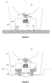
- Figures 8 and 9 represent a preferred embodiment of a beverage discharge disposition (2) in a system according to the present invention.
- said engagement portion (16) of beverage recipient (1) is adapted so that can be retained by engagement elements (23) provided so that can be radially moved between an open position (I) e and a retention position (II) where they engaged with said engagement portion (16) thereby retaining said beverage recipient (1, 1') on said recipient placement surface (22), and vice-versa, between the retention position (II) and the open position (I).
- said beverage discharge disposition (2) comprises four engagement elements (23) that present an engagement part (231) configured in a hook type form, of inverted "L" type, or similar, that projects above the recipient placement surface (22) and is adapted so as to engage with said engagement portion (16) of beverage recipients (1, 1'), and first and second actuation parts (232, 233) adapted so that can be actuated by respective actuation means (251, 252) provided underneath the recipient placement surface (22).
- Figures 10 and 11 represent the embodiment according to Figures 8 and 9 , in an open position (I) and in a retention position (II), respectively.
- said beverage discharge disposition (2) comprises first actuation means (251) provided as elastic means and disposed so that impinge with an elastic force, radially inwards, said first actuation part (232) of each engagement element (23) to a corresponding open position (I), and second actuation means (252) adapted so that move vertically said beverage discharge element (21), so that when moving upwards pressure radially outwards said second actuation part (232) of said retention elements (23) against the action of said elastic means (251), so that the retention elements (23) move radially outwards and the respective engagement part (231) engages with said engagement portion (16) of beverage recipients (1, 1') in a retention position (II), and vice-versa, between a retention position (II) and an open position (I).
- first actuation means 251 provided as elastic means and disposed so that impinge with an elastic force, radially inwards, said first actuation part (232) of each engagement element (23) to a corresponding open position (I)
- the actuation means include at least one of elastic means and electro-mechanic means, preferentially hydraulic means.
- beverage discharge disposition (2) is controlled between the open (I) and retention positions (II) by means of a device controlling the operation of the beverage preparation apparatus (3), according to at least one of: a sensor of presence of beverage recipient (1, 1') on said beverage discharge disposition (2), and an actuation interface of beverage preparation apparatus (3).
- said beverage apparatus (3) further comprises state presentation means (not represented) adapted so as to communicate to the user a correct placement of the beverage recipient (1, 1') in the beverage discharge disposition (2), whereby said state presentation means are of at least one type including a visual and an acoustic type, and preferentially provided associated with said beverage discharge disposition (2) .
- Figure 12 represents a preferred embodiment of said engagement elements (23).
- said engagement elements (23) present a respective first actuation part (232) adapted so that can be impinged by first actuation means (251) with a force along a direction transversal relative to the prevailing beverage discharge direction, between an un-compressed position corresponding to the open position (I), and a compressed position corresponding to the retention position (II), and vice-versa.
- said engagement elements (23) present a respective second actuation part (233) comprising an inclined surface, oriented inwards with relation to the central region of said beverage discharge disposition (2), and adapted so that said inclined surface is impinged outwards by second actuation means (252) that move in an ascending movement, and vice-versa.
- beverage discharge disposition (2) present engagement elements (23) with a total height of at most 60 mm, preferentially comprised between 20 and 60 mm, particularly preferentially between 30 and 40 mm, and in that said engagement part (231) presents a height of at most 10 mm, and the transversal hook form portion develops at least 2 mm beyond the vertical portion.
Landscapes
- Engineering & Computer Science (AREA)
- Food Science & Technology (AREA)
- Mechanical Engineering (AREA)
- Physics & Mathematics (AREA)
- Thermal Sciences (AREA)
- Apparatus For Making Beverages (AREA)
Claims (14)
- System zur Getränkeverteilung beinhaltend:- mindestens ein Typ von einem Getränkebehälter (1, 1') mit einem Sammelraum (A) sich aufwärts von der Grundwand (11) entwickelnd, die eine Durchflussöffnung (110) aufweist, einer Durchflussregulierungsvorrichtung (12), die einen Durchfluss bereitstellt, wenn er mit mindestens einem bestimmten Durchflussdruck stromaufwärts beaufschlagt wird, und einer Betätigungsmenge (16);- mindestens ein Typ von einem Getränkegerät (3) betrieblich verbunden mit einer Getränkeentladungsvorrichtung (2), die ein Getränkeentladungselement (21) umfasst, so ausgerichtet, um das Getränk mit genanntem Durchflussdruck stromaufwärts zu entladen, und einer Behälterablageoberfläche (22), die genanntes Getränkeentladungselement (21) umgibt,genannte Getränkeentladungsvorrichtung (2) aufweisend Betätigungselemente (23), die zwischen einer offenen Position (I) kann gefahren werden, die die Bereitstellung von genannten Getränkebehältern (1, 1') auf genannter Behälterablageoberfläche (22) ermöglicht, und eine geschlossene Position (I), in der genannte Betätigungsmenge (16) betätigt wird, um dabei genanntes Getränkebehälter (1, 1') auf genannter Behälterablageoberfläche (22) aufzustauen, und umgekehrt, zwischen der anhaltenden Position (II) und der offenen Position (I),wobeigenannte Getränkeentladungsvorrichtung (2) eine Vielzahl an Betätigungselementen (23) aufweist, die einer Reihe entlang angeordnet sind, die genanntes Getränkeentladungselement (21) und mindestens annähernd symmetrisch davon umgibt, und so bereitgestellt, um zwischen genannter offenen (I) und anhaltenden Position (II) bewegt zu werden, und umgekehrt, mittels Betätigungsmittel (25; 251; 252) angeordnet mittig und symmetrisch zu genanntem Getränkeentladungselement (21)dadurch gekennzeichnet, dassgenannte Betätigungselementen (23) so bereitgestellt werden, um gemeinsam in eine radial nach außen oder nach innen gerichtete Gleitbewegung gefahren zu werden ohne Drehung zu genanntem Getränkeentladungselement (21), und dadurch, dass genannte radiale Gleitbewegung der Betätigungselemente (23) betrieblich auf eine aufsteigenden Bewegung von genanntem Getränkeentladungselement (21) zwischen einer entsprechenden Sammelposition und einer Ausladeposition bezogen ist, indem sie neben genannter Durchflussregulierungsvorrichtung (12) ist, und umgekehrt.
- System gemäß Anspruch 1 dadurch gekennzeichnet, dass genannte Betätigungselemente (23) aufwärts von genannter Behälterablageoberfläche (22) und oberhalb einer Oberfläche ausladen, die sich oberhalb und um genannte Behälterablageoberfläche (22) herum entwickelt, und
dass jedes der genannten Betätigungselemente (23) ein Betätigungselement (231) gestaltet in einer hakenähnlichen, umgekehrten L-Form oder ähnlich aufweist, die oberhalb der Behälterablageoberfläche (22) entlädt und so angepasst, um mit genannter Betätigungsmenge (16) der Getränkebehältern (1, 1') betätigt zu werden, wobei jedes der genannten Betätigungselemente (23) weiterhin erste und zweite Betätigungselemente (232, 233) aufweist und so angepasst, um mittels Betätigungsmittel (25; 251; 252) vorhanden unterhalb genannter Behälterablageoberfläche (22) gefahren zu werden. - System gemäß der Ansprüche 1 oder 2 dadurch gekennzeichnet, dass genannte Betätigungselemente (23) und genannte Getränkeentladungselement (21) so angepasst sind, um mittels entsprechende Betätigungsmittel (251, 252) gefahren zu werden, die betrieblich mittels eines gemeinsamen Betätigungsgeräts gefahren werden, das so angepasst ist, dass eine entsprechende Richtung einer Betätigungskraft mindestens annähernd parallel zur, vorzugsweise mit der mittigen Längsachse von genanntem Getränkeentladungselement (21) entlang der gegebenen Entladungsströmungsrichtung davon angeordnet ist.
- System gemäß einer der Ansprüche 1 bis 3 dadurch gekennzeichnet, dass genannte Getränkeentladungsvorrichtung (2) erste Betätigungsmittel (251) umfasst, die als elastische Mittel vorhanden sind und so angeordnet, um mit einer Federkraft radial einwärts auszuwirken, genanntes erstes Betätigungselement (232) von jedem Betätigungselement (23) in Richtung einer entsprechenden offenen Position (I), und genannte Betätigungsmittel (252) so angepasst sind, um sich senkrecht von genanntem Getränkeentladungselement (21) so zu bewegen, dass sie radial auswärts von genanntem zweiten Betätigungsmittel (232) von genannten Betätigungselementen (23) gegen Betätigung genannter elastischen Mitteln (251) drücken, wenn sie sich aufwärts bewegen, so dass sich die Betätigungselemente (23) radial auswärts bewegen und der entsprechende Betätigungsmittel (231) mit genannter Betätigungsmenge (16) der Getränkebehälter (1, 1') in geschlossener Position (II) zwischen einer geschlossener Position (II) und einer offenen Position (I) und umgekehrt betätigt wird.
- System gemäß der Ansprüche 1 bis 4 dadurch gekennzeichnet, dass genannte Betätigungselemente (23) einen enstsprechenden ersten Betätigungsteil (232) aufweist und so angepasst, um mittels erster Betätigungsmittel (251) mit einer Kraft entlang einer Querrichtung bzgl. der gegebenen Getränkeentladungsrichtung zwischen einer unkomprimierten Position entsprechend der offenen Position (I) und einer komprimierten Position entsprechend der geschlossenen Position (II) und umgekehrt auszuwirken.
- System gemäß einer der Ansprüche 1 bis 5 dadurch gekennzeichnet, dass genannte Betätigungselemente (23) einen enstsprechenden zweiten Betätigungsteil (233) aufweist, der eine geneigte Oberfläche gerichtet nach innen bzgl. dem mittigen Bereich von genannter Getränkeentladungsvorrichtung umfasst und so angepasst, dass genannte geneigte Oberfläche mittels zweiter Betätigungsmittel (252) auswärts auswirkt, die sich steigend und umgekehrt bewegen.
- System gemäß einer der vorigen Ansprüche 1 bis 6 dadurch gekennzeichnet, dass genannte Betätigungselemente (23) so bereitgestellt sind, dass nur der entsprechende Betätigungsteil (231) oberhalb der Behälterablageoberfläche (22) spiegelt, und eine Gesamthöhe von meistenteils 60 mm aufweisen, vorzugsweise zwischen 20 und 60 mm umfasst, jedenfalls vorzugsweise zwischen 30 und 40 mm umfasst, und dass genannter Betätigungsteil (231) eine Höhe von meistenteils 10 mm aufweist, und sich die Quermenge einer Hakenform mindestens 2 mm jenseits der senkrechten Menge entwickelt.
- System gemäß einer der vorigen Ansprüche 1 bis 7 dadurch gekennzeichnet, dass genannte Getränkeentladungsvorrichtung (2) so bereitgestellt ist, dass die Betätigungsmittel (25; 251; 252) mindestens eine der elastischen Mitteln, elektromechanischen Mitteln und hydraulischen Mitteln beinhaltet.
- System gemäß einer der vorigen Ansprüche 1 bis 8 dadurch gekennzeichnet, dass genannte Getränkeentladungsvorrichtung (2) zwischen der offenen (I) und der geschlossenen (II) Position mittels eines Kontrollgeräts kontrolliert wird, das mit dem Getränkegerät (3) betrieblich verbunden ist gemäß mindestens eins von:- einem Bewegungssensor des Getränkebehälters (1, 1') mit genannter Getränkeentladungsvorrichtung (2) betrieblich verbunden, und- einer Antriebsschnittstelle des Getränkegeräts (3).
- System gemäß einer der vorigen Ansprüche dadurch gekennzeichnet, dass genannter Getränkebehälter (1, 1') eine stromgebundene Vorrichtung (13) weiterhin umfasst, die mit genannter Durchgangsöffnung (110) stromabwärts von genannter Durchflussregulierungsvorrichtung (12) verbunden ist, und so gestaltet, um mindestens eine gegebene Stromrichtung und einen Stromdurchgangsbereich entlang der stromgebundenen Vorrichtung (13) so zu ändern, dass sich der Strommuster am Grundbereicheingang des Sammelraumes (A) vom Strommuster direkt stromabwärts von genannter Durchflussregulierungsvorrichtung (12) unterscheidet.
- System gemäß einer der vorigen Ansprüche dadurch gekennzeichnet, dass genannter Getränkebehälter (1, 1') eine Betätigungsmenge (16) aufweist, die sich von genannter Grundmenge (11) entwickelt und so angepasst ist, dass genannter Getränkebehälter (1, 1') in genannter Behälterablageoberfläche (22) mittels genannter Betätigungselemente (23) aufgefangen werden und so angepasst, um mechanisch mit genannter Betätigungsmenge (16) zu betätigen, so dass genannte Durchflussregulierungsvorrichtung (12) oberhalb von genanntem Getränkeentladungselement (21) senkrecht angeordnet aufgefangen ist.
- System gemäß einer der vorigen Ansprüche dadurch gekennzeichnet, dass genannter Getränkebehälter (1, 1') eine Betätigungsmenge (16) aufweist, die einen ersten Teil (161) umfasst, der sich abwärts entwickelt, und einen zweiten Teil (162), der sich entlang einer Querrichtung bzgl. des mittigen Getränkebehälters (1, 1') entwickelt, wobei genannte ersten und zweiten Teile (161, 162) mit einer Form gestaltet sind, die Fittingsbetätigung der Betätigungselement (23) mit genannter Getränkeentladungsvorrichtung (2) verbunden bereitstellt, insbesondere eine Betätigungstiefe (d) und eine Betätigungshöhe (h) größer als 0,5 mm und kleiner als 25 mm und vorzugsweise bereitstellend eine freie Höhe (h') aufweist, die vorzugsweise größer als genannte Betätigungshöhe (h) innerhalb des Bereiches ist, den sie oberhalb der Behälterablageoberfläche (22) abgrenzen.
- System gemäß einer der vorigen Ansprüche dadurch gekennzeichnet, dass genanntes Getränkegerät (3) ein Getränkezubereitungsgerät ist, insbesondere Espresso und ähnliche Getränke, und von stromaufwärts bis zu stromabwärts entlang der Stromrichtung umfasst:- ein Durchflussdruckgerät (7), z.Bsp. eine Hydraulikpumpe so angepasst, um eine Flüssigkeitszufuhr (FS) bei einem Druck umfasst zwischen 1 und 20 Bar, vorzugsweise mindestens 10 Bar, zu liefern,- ein Braugerät (4) so angepasst, um eine essbare Menge (5) zu sammeln, wahlweise innerhalb einer Kapsel bereitgestellt, und um einen Getränkeentladungsdurchfluss (BD) der ergebenen Getränke zu liefern,- eine Getränkeentladungsvorrichtung (2) so angepasst, um die Unterstützung für die Lage von mindestens einem, vorzugsweise einer Vielzahl von Typen von Getränkebehältern (1, 1') und Entladung von genanntem Getränkeentladungsdurchfluss (BD) innerhalb von genanntem Sammelraum (A) bereitzustellen,wobei genanntes Getränkezubereitungsgerät (3) eine Öffnung (8) aufweist und so angepasst, um die Einführung einer essbaren Menge (5) bereitzustellen, zu schließen und Verbindung zu genanntem Braugerät (4) zu liefern, und angepasst zur Versorgung von genannter essbaren Menge (5), wobei genannte Öffnung (8) neben genannter Getränkeentladungsvorrichtung (2), vorzugsweise in der selben Außenoberfläche von genanntem Getränkezubereitungsgerät (3) bereitgestellt ist.
- System gemäß einer der vorigen Ansprüche dadurch gekennzeichnet, dass eine Vielzahl an Typen von Getränkebehältern (1, 1') beinhaltet ist und verschiedene Dimensionen, insbesondere mindestens einer der verschiedenen Dimensionen des Sammelraumes (A) und verschiedenen Dimensionen der entsprechenden Grundwände (11) aufgewiesen werden, und so angepasst, um mittels mechanischer Betätigung in einem gleichen Typ der Getränkeentladungsvorrichtung (2) aufzufangen, insbesondere aufweisend eine Betätigungsmenge (16) mit ähnlicher Betätigungshöhe (h), wobei mindestens eins der Typen von Getränkebehältern (1, 1') vorzugsweise kein Einwegbehälter ist.
Applications Claiming Priority (2)
| Application Number | Priority Date | Filing Date | Title |
|---|---|---|---|
| PT11003217 | 2017-04-18 | ||
| PCT/PT2018/050015 WO2018194476A1 (pt) | 2017-04-18 | 2018-04-16 | Sistema de distribuição de bebidas com retenção optimizada de recipientes de bebidas |
Publications (2)
| Publication Number | Publication Date |
|---|---|
| EP3613318A1 EP3613318A1 (de) | 2020-02-26 |
| EP3613318B1 true EP3613318B1 (de) | 2024-07-24 |
Family
ID=62563224
Family Applications (1)
| Application Number | Title | Priority Date | Filing Date |
|---|---|---|---|
| EP18730139.5A Active EP3613318B1 (de) | 2017-04-18 | 2018-04-16 | Getränkeausgabesystem mit optimierter getränkebehälterrückhaltung |
Country Status (7)
| Country | Link |
|---|---|
| US (1) | US11627830B2 (de) |
| EP (1) | EP3613318B1 (de) |
| CN (1) | CN110520023B (de) |
| BR (1) | BR112019019267A2 (de) |
| CA (1) | CA3059050A1 (de) |
| PL (1) | PL3613318T3 (de) |
| WO (1) | WO2018194476A1 (de) |
Families Citing this family (2)
| Publication number | Priority date | Publication date | Assignee | Title |
|---|---|---|---|---|
| JP7419363B2 (ja) * | 2018-10-23 | 2024-01-22 | ノヴァデルタ - コメルシオ エ インダストリア デ カフェス,エルディーエー | 食用製品を受領容器に前記受領容器によって調節された状態において分配するシステム及びプロセス |
| AU2020448904A1 (en) * | 2020-05-20 | 2022-11-24 | Essity Hygiene And Health Aktiebolag | An adaptor assembly for a fluid dispensing system |
Family Cites Families (24)
| Publication number | Priority date | Publication date | Assignee | Title |
|---|---|---|---|---|
| DE19853593C1 (de) * | 1998-11-20 | 2000-04-20 | Technotrans Ag | Füllvorrichtung für Kartuschen |
| US6698624B2 (en) * | 2001-04-04 | 2004-03-02 | Nestec S.A. | Device for dispensing a flowable powder substance |
| EP1343356B1 (de) * | 2002-03-05 | 2012-12-26 | LG Electronics, Inc. | Mit einer Kaffeemaschine versehener Mikrowellenofen |
| MX2007003792A (es) * | 2004-10-01 | 2007-07-11 | Hausbrandt Trieste 1892 Spa | Aparato y metodo para preparar y suministrar una bebida con el uso de una materia prima contenida macias en un cartucho. |
| CN2824798Y (zh) * | 2005-09-27 | 2006-10-11 | 刘志洪 | 一种可调出水口高度的分流器 |
| ITCS20060009A1 (it) * | 2006-09-14 | 2008-03-15 | Franco Candelise | Bocchettone atto ad evitare errori nel riempimento di serbatoi e recipienti |
| US10258186B2 (en) * | 2013-02-01 | 2019-04-16 | Adrian Rivera | Brewing cartridge |
| ES2369474T3 (es) * | 2008-02-08 | 2011-12-01 | Celaya, Emparanza Y Galdós Internacional, S.A. | Portafiltros para cafetera. |
| CN101292842A (zh) * | 2008-05-16 | 2008-10-29 | 谢鑫桥 | 果汁搅拌杯联动机构及联动方法 |
| DE102009048233B4 (de) * | 2008-10-06 | 2018-12-13 | Volkswagen Ag | Vorrichtung zur Zubereitung von flüssigen Lebensmitteln, inbesondere zur Zubereitung von Heißgetränken, Suppen oder dergleichen und Mehrkammerbehälter, insbesondere zur Verwendung in der Vorrichtung |
| DE102008050532A1 (de) * | 2008-10-06 | 2010-04-08 | Volkswagen Ag | Vorrichtung zur Heißwasser- und/oder Dampferzeugung und/oder zur Zubereitung von flüssigen Lebensmitteln, insbesondere von Kaffee, Tee oder dergleichen |
| DE102009012055A1 (de) * | 2009-03-06 | 2010-09-09 | Volkswagen Ag | Zapfstellenmodul für Heißwasser und/oder Dampf in einem Fahrzeug, insbesondere in einem Kraftfahrzeug |
| CN101653340B (zh) * | 2009-09-03 | 2011-09-28 | 晶辉科技(深圳)有限公司 | 具有前门结构的多士炉 |
| CN201781916U (zh) * | 2010-08-23 | 2011-04-06 | 九阳股份有限公司 | 升降式豆浆机 |
| TW201318564A (zh) * | 2011-06-15 | 2013-05-16 | Green Mountain Coffee Roasters Inc | 飲料形成設備及使用振動能的方法 |
| CN202225111U (zh) * | 2011-08-17 | 2012-05-23 | 浙江瑞华机械有限公司 | 一种夹紧容器颈口的装置 |
| DE202012103158U1 (de) * | 2012-08-21 | 2013-11-25 | Melitta Europa Gmbh & Co. Kg | Kaffeemaschine |
| CN202843130U (zh) * | 2012-10-19 | 2013-04-03 | 宁波西摩电器有限公司 | 泡制装置及其泡制物容器升降结构 |
| WO2014086915A1 (en) * | 2012-12-07 | 2014-06-12 | Nestec S.A. | Beverage production device with enhanced receptacle injection means |
| PT106862B (pt) * | 2013-04-02 | 2020-11-11 | Novadelta - Comércio E Indústria De Cafés, Lda. | Máquina de preparação de bebidas de baixa voltagem e processo de operação da mesma |
| US9345359B2 (en) * | 2014-07-14 | 2016-05-24 | La Colombe Torrefaction, Inc. | Coffee brewing device with manual siphon and method of brewing with same |
| CN204146870U (zh) * | 2014-09-19 | 2015-02-11 | 陈伟 | 一种可切换的多功能咖啡冲泡器 |
| CN104329316B (zh) * | 2014-10-31 | 2016-08-17 | 罗斯(无锡)设备有限公司 | 一种安全锁紧机构 |
| CN106361148B (zh) * | 2015-07-23 | 2019-10-29 | 吉诺工业有限公司 | 饮料冲泡装置 |
-
2018
- 2018-04-16 CA CA3059050A patent/CA3059050A1/en not_active Abandoned
- 2018-04-16 EP EP18730139.5A patent/EP3613318B1/de active Active
- 2018-04-16 US US16/605,891 patent/US11627830B2/en active Active
- 2018-04-16 CN CN201880025421.6A patent/CN110520023B/zh active Active
- 2018-04-16 WO PCT/PT2018/050015 patent/WO2018194476A1/pt not_active Ceased
- 2018-04-16 BR BR112019019267A patent/BR112019019267A2/pt not_active Application Discontinuation
- 2018-04-16 PL PL18730139.5T patent/PL3613318T3/pl unknown
Also Published As
| Publication number | Publication date |
|---|---|
| CA3059050A1 (en) | 2018-10-25 |
| US11627830B2 (en) | 2023-04-18 |
| WO2018194476A1 (pt) | 2018-10-25 |
| EP3613318A1 (de) | 2020-02-26 |
| US20210121001A1 (en) | 2021-04-29 |
| CN110520023B (zh) | 2022-02-08 |
| PL3613318T3 (pl) | 2024-12-02 |
| CN110520023A (zh) | 2019-11-29 |
| BR112019019267A2 (pt) | 2020-04-14 |
Similar Documents
| Publication | Publication Date | Title |
|---|---|---|
| CN109195489B (zh) | 利用最佳饮料排放装置制备芳香饮料的系统和所述系统的操作方法 | |
| EP3613317B1 (de) | Getränkeausgabesystem mit optimierter getränkeausgabeanordnung | |
| EP1804630B1 (de) | Getränkeherstellungsvorrichtung mit einer braukammer und druckentlastungsmitteln | |
| US11627830B2 (en) | Beverage distribution system with optimized retention of beverage recipients | |
| AU2019316518B2 (en) | Beverage distribution system with composite drinking vessels, and process of operation thereof | |
| EP2767198B1 (de) | Filterhalter für eine Espresso-Kaffeemaschine | |
| EP2036469B1 (de) | Espressomaschine mit einem Auslass-Labyrinth | |
| EP2103235B1 (de) | Verbesserte Espressokaffeemaschine mit Ablaufweg | |
| AU2019314127B2 (en) | Beverage distribution system with ergonomic retention of drinking vessels, and process of operation thereof | |
| US20210186254A1 (en) | System for preparing beverages with shape retention of beverage recipients | |
| EP3831254B1 (de) | Getränkeautomat mit verbesserter spülung und rückstandsentleerung, und verfahren zum betreiben des systems | |
| EP4052619A1 (de) | Trinkbehälter mit verbesserten durchflussreguliermitteln, systeme und verfahren mit diesen trinkbehältern | |
| HK1260523A1 (en) | System for preparing aromatic beverages with optimised beverage discharge arrangement, and method for operating this system | |
| HK1260523B (zh) | 利用最佳饮料排放装置制备芳香饮料的系统和所述系统的操作方法 | |
| ES2988623T3 (es) | Sistema dispensador de bebidas con retención optimizada del receptáculo para bebida | |
| EP3199072B1 (de) | System zur herstellung eines flüssigen getränks aus einer kapsel, eine zur verwendung in einem system konfigurierte kapsel | |
| EP4706466A1 (de) | Systeme und verfahren zur ausgabe von essbaren flüssigkeitsprodukten mit ausflussadapter für das essbare flüssigkeitsprodukt |
Legal Events
| Date | Code | Title | Description |
|---|---|---|---|
| STAA | Information on the status of an ep patent application or granted ep patent |
Free format text: STATUS: UNKNOWN |
|
| STAA | Information on the status of an ep patent application or granted ep patent |
Free format text: STATUS: THE INTERNATIONAL PUBLICATION HAS BEEN MADE |
|
| PUAI | Public reference made under article 153(3) epc to a published international application that has entered the european phase |
Free format text: ORIGINAL CODE: 0009012 |
|
| STAA | Information on the status of an ep patent application or granted ep patent |
Free format text: STATUS: REQUEST FOR EXAMINATION WAS MADE |
|
| 17P | Request for examination filed |
Effective date: 20191105 |
|
| AK | Designated contracting states |
Kind code of ref document: A1 Designated state(s): AL AT BE BG CH CY CZ DE DK EE ES FI FR GB GR HR HU IE IS IT LI LT LU LV MC MK MT NL NO PL PT RO RS SE SI SK SM TR |
|
| AX | Request for extension of the european patent |
Extension state: BA ME |
|
| DAV | Request for validation of the european patent (deleted) | ||
| DAX | Request for extension of the european patent (deleted) | ||
| STAA | Information on the status of an ep patent application or granted ep patent |
Free format text: STATUS: EXAMINATION IS IN PROGRESS |
|
| 17Q | First examination report despatched |
Effective date: 20201208 |
|
| RAP3 | Party data changed (applicant data changed or rights of an application transferred) |
Owner name: NOVADELTA - COMERCIO E INDUSTRIA DE CAFES, UNIPESSOAL LDA |
|
| GRAP | Despatch of communication of intention to grant a patent |
Free format text: ORIGINAL CODE: EPIDOSNIGR1 |
|
| STAA | Information on the status of an ep patent application or granted ep patent |
Free format text: STATUS: GRANT OF PATENT IS INTENDED |
|
| INTG | Intention to grant announced |
Effective date: 20240426 |
|
| GRAS | Grant fee paid |
Free format text: ORIGINAL CODE: EPIDOSNIGR3 |
|
| GRAA | (expected) grant |
Free format text: ORIGINAL CODE: 0009210 |
|
| STAA | Information on the status of an ep patent application or granted ep patent |
Free format text: STATUS: THE PATENT HAS BEEN GRANTED |
|
| AK | Designated contracting states |
Kind code of ref document: B1 Designated state(s): AL AT BE BG CH CY CZ DE DK EE ES FI FR GB GR HR HU IE IS IT LI LT LU LV MC MK MT NL NO PL PT RO RS SE SI SK SM TR |
|
| REG | Reference to a national code |
Ref country code: GB Ref legal event code: FG4D |
|
| REG | Reference to a national code |
Ref country code: CH Ref legal event code: EP |
|
| REG | Reference to a national code |
Ref country code: PT Ref legal event code: SC4A Ref document number: 3613318 Country of ref document: PT Date of ref document: 20240808 Kind code of ref document: T Free format text: AVAILABILITY OF NATIONAL TRANSLATION Effective date: 20240802 |
|
| REG | Reference to a national code |
Ref country code: IE Ref legal event code: FG4D Ref country code: DE Ref legal event code: R096 Ref document number: 602018072160 Country of ref document: DE |
|
| REG | Reference to a national code |
Ref country code: LT Ref legal event code: MG9D |
|
| P01 | Opt-out of the competence of the unified patent court (upc) registered |
Free format text: CASE NUMBER: APP_56351/2024 Effective date: 20241015 |
|
| REG | Reference to a national code |
Ref country code: ES Ref legal event code: FG2A Ref document number: 2988623 Country of ref document: ES Kind code of ref document: T3 Effective date: 20241121 |
|
| REG | Reference to a national code |
Ref country code: NL Ref legal event code: MP Effective date: 20240724 |
|
| REG | Reference to a national code |
Ref country code: AT Ref legal event code: MK05 Ref document number: 1705453 Country of ref document: AT Kind code of ref document: T Effective date: 20240724 |
|
| PG25 | Lapsed in a contracting state [announced via postgrant information from national office to epo] |
Ref country code: NL Free format text: LAPSE BECAUSE OF FAILURE TO SUBMIT A TRANSLATION OF THE DESCRIPTION OR TO PAY THE FEE WITHIN THE PRESCRIBED TIME-LIMIT Effective date: 20240724 |
|
| PG25 | Lapsed in a contracting state [announced via postgrant information from national office to epo] |
Ref country code: NL Free format text: LAPSE BECAUSE OF FAILURE TO SUBMIT A TRANSLATION OF THE DESCRIPTION OR TO PAY THE FEE WITHIN THE PRESCRIBED TIME-LIMIT Effective date: 20240724 |
|
| PG25 | Lapsed in a contracting state [announced via postgrant information from national office to epo] |
Ref country code: NO Free format text: LAPSE BECAUSE OF FAILURE TO SUBMIT A TRANSLATION OF THE DESCRIPTION OR TO PAY THE FEE WITHIN THE PRESCRIBED TIME-LIMIT Effective date: 20241024 |
|
| PG25 | Lapsed in a contracting state [announced via postgrant information from national office to epo] |
Ref country code: GR Free format text: LAPSE BECAUSE OF FAILURE TO SUBMIT A TRANSLATION OF THE DESCRIPTION OR TO PAY THE FEE WITHIN THE PRESCRIBED TIME-LIMIT Effective date: 20241025 Ref country code: FI Free format text: LAPSE BECAUSE OF FAILURE TO SUBMIT A TRANSLATION OF THE DESCRIPTION OR TO PAY THE FEE WITHIN THE PRESCRIBED TIME-LIMIT Effective date: 20240724 |
|
| PG25 | Lapsed in a contracting state [announced via postgrant information from national office to epo] |
Ref country code: BG Free format text: LAPSE BECAUSE OF FAILURE TO SUBMIT A TRANSLATION OF THE DESCRIPTION OR TO PAY THE FEE WITHIN THE PRESCRIBED TIME-LIMIT Effective date: 20240724 |
|
| PG25 | Lapsed in a contracting state [announced via postgrant information from national office to epo] |
Ref country code: LV Free format text: LAPSE BECAUSE OF FAILURE TO SUBMIT A TRANSLATION OF THE DESCRIPTION OR TO PAY THE FEE WITHIN THE PRESCRIBED TIME-LIMIT Effective date: 20240724 |
|
| PG25 | Lapsed in a contracting state [announced via postgrant information from national office to epo] |
Ref country code: IS Free format text: LAPSE BECAUSE OF FAILURE TO SUBMIT A TRANSLATION OF THE DESCRIPTION OR TO PAY THE FEE WITHIN THE PRESCRIBED TIME-LIMIT Effective date: 20241124 Ref country code: AT Free format text: LAPSE BECAUSE OF FAILURE TO SUBMIT A TRANSLATION OF THE DESCRIPTION OR TO PAY THE FEE WITHIN THE PRESCRIBED TIME-LIMIT Effective date: 20240724 |
|
| PG25 | Lapsed in a contracting state [announced via postgrant information from national office to epo] |
Ref country code: HR Free format text: LAPSE BECAUSE OF FAILURE TO SUBMIT A TRANSLATION OF THE DESCRIPTION OR TO PAY THE FEE WITHIN THE PRESCRIBED TIME-LIMIT Effective date: 20240724 |
|
| PG25 | Lapsed in a contracting state [announced via postgrant information from national office to epo] |
Ref country code: RS Free format text: LAPSE BECAUSE OF FAILURE TO SUBMIT A TRANSLATION OF THE DESCRIPTION OR TO PAY THE FEE WITHIN THE PRESCRIBED TIME-LIMIT Effective date: 20241024 |
|
| PG25 | Lapsed in a contracting state [announced via postgrant information from national office to epo] |
Ref country code: RS Free format text: LAPSE BECAUSE OF FAILURE TO SUBMIT A TRANSLATION OF THE DESCRIPTION OR TO PAY THE FEE WITHIN THE PRESCRIBED TIME-LIMIT Effective date: 20241024 Ref country code: NO Free format text: LAPSE BECAUSE OF FAILURE TO SUBMIT A TRANSLATION OF THE DESCRIPTION OR TO PAY THE FEE WITHIN THE PRESCRIBED TIME-LIMIT Effective date: 20241024 Ref country code: LV Free format text: LAPSE BECAUSE OF FAILURE TO SUBMIT A TRANSLATION OF THE DESCRIPTION OR TO PAY THE FEE WITHIN THE PRESCRIBED TIME-LIMIT Effective date: 20240724 Ref country code: IS Free format text: LAPSE BECAUSE OF FAILURE TO SUBMIT A TRANSLATION OF THE DESCRIPTION OR TO PAY THE FEE WITHIN THE PRESCRIBED TIME-LIMIT Effective date: 20241124 Ref country code: HR Free format text: LAPSE BECAUSE OF FAILURE TO SUBMIT A TRANSLATION OF THE DESCRIPTION OR TO PAY THE FEE WITHIN THE PRESCRIBED TIME-LIMIT Effective date: 20240724 Ref country code: GR Free format text: LAPSE BECAUSE OF FAILURE TO SUBMIT A TRANSLATION OF THE DESCRIPTION OR TO PAY THE FEE WITHIN THE PRESCRIBED TIME-LIMIT Effective date: 20241025 Ref country code: FI Free format text: LAPSE BECAUSE OF FAILURE TO SUBMIT A TRANSLATION OF THE DESCRIPTION OR TO PAY THE FEE WITHIN THE PRESCRIBED TIME-LIMIT Effective date: 20240724 Ref country code: BG Free format text: LAPSE BECAUSE OF FAILURE TO SUBMIT A TRANSLATION OF THE DESCRIPTION OR TO PAY THE FEE WITHIN THE PRESCRIBED TIME-LIMIT Effective date: 20240724 Ref country code: AT Free format text: LAPSE BECAUSE OF FAILURE TO SUBMIT A TRANSLATION OF THE DESCRIPTION OR TO PAY THE FEE WITHIN THE PRESCRIBED TIME-LIMIT Effective date: 20240724 |
|
| PG25 | Lapsed in a contracting state [announced via postgrant information from national office to epo] |
Ref country code: DK Free format text: LAPSE BECAUSE OF FAILURE TO SUBMIT A TRANSLATION OF THE DESCRIPTION OR TO PAY THE FEE WITHIN THE PRESCRIBED TIME-LIMIT Effective date: 20240724 Ref country code: SM Free format text: LAPSE BECAUSE OF FAILURE TO SUBMIT A TRANSLATION OF THE DESCRIPTION OR TO PAY THE FEE WITHIN THE PRESCRIBED TIME-LIMIT Effective date: 20240724 Ref country code: RO Free format text: LAPSE BECAUSE OF FAILURE TO SUBMIT A TRANSLATION OF THE DESCRIPTION OR TO PAY THE FEE WITHIN THE PRESCRIBED TIME-LIMIT Effective date: 20240724 |
|
| PG25 | Lapsed in a contracting state [announced via postgrant information from national office to epo] |
Ref country code: EE Free format text: LAPSE BECAUSE OF FAILURE TO SUBMIT A TRANSLATION OF THE DESCRIPTION OR TO PAY THE FEE WITHIN THE PRESCRIBED TIME-LIMIT Effective date: 20240724 |
|
| PG25 | Lapsed in a contracting state [announced via postgrant information from national office to epo] |
Ref country code: CZ Free format text: LAPSE BECAUSE OF FAILURE TO SUBMIT A TRANSLATION OF THE DESCRIPTION OR TO PAY THE FEE WITHIN THE PRESCRIBED TIME-LIMIT Effective date: 20240724 |
|
| REG | Reference to a national code |
Ref country code: DE Ref legal event code: R097 Ref document number: 602018072160 Country of ref document: DE |
|
| PG25 | Lapsed in a contracting state [announced via postgrant information from national office to epo] |
Ref country code: SK Free format text: LAPSE BECAUSE OF FAILURE TO SUBMIT A TRANSLATION OF THE DESCRIPTION OR TO PAY THE FEE WITHIN THE PRESCRIBED TIME-LIMIT Effective date: 20240724 Ref country code: IT Free format text: LAPSE BECAUSE OF FAILURE TO SUBMIT A TRANSLATION OF THE DESCRIPTION OR TO PAY THE FEE WITHIN THE PRESCRIBED TIME-LIMIT Effective date: 20240724 |
|
| PLBE | No opposition filed within time limit |
Free format text: ORIGINAL CODE: 0009261 |
|
| STAA | Information on the status of an ep patent application or granted ep patent |
Free format text: STATUS: NO OPPOSITION FILED WITHIN TIME LIMIT |
|
| 26N | No opposition filed |
Effective date: 20250425 |
|
| PGFP | Annual fee paid to national office [announced via postgrant information from national office to epo] |
Ref country code: DE Payment date: 20250428 Year of fee payment: 8 |
|
| PGFP | Annual fee paid to national office [announced via postgrant information from national office to epo] |
Ref country code: ES Payment date: 20250516 Year of fee payment: 8 |
|
| PGFP | Annual fee paid to national office [announced via postgrant information from national office to epo] |
Ref country code: PT Payment date: 20250414 Year of fee payment: 8 |
|
| PGFP | Annual fee paid to national office [announced via postgrant information from national office to epo] |
Ref country code: FR Payment date: 20250428 Year of fee payment: 8 |
|
| PGFP | Annual fee paid to national office [announced via postgrant information from national office to epo] |
Ref country code: CH Payment date: 20250501 Year of fee payment: 8 |
|
| PG25 | Lapsed in a contracting state [announced via postgrant information from national office to epo] |
Ref country code: SE Free format text: LAPSE BECAUSE OF FAILURE TO SUBMIT A TRANSLATION OF THE DESCRIPTION OR TO PAY THE FEE WITHIN THE PRESCRIBED TIME-LIMIT Effective date: 20240724 |
|
| PG25 | Lapsed in a contracting state [announced via postgrant information from national office to epo] |
Ref country code: LU Free format text: LAPSE BECAUSE OF NON-PAYMENT OF DUE FEES Effective date: 20250416 |
|
| PG25 | Lapsed in a contracting state [announced via postgrant information from national office to epo] |
Ref country code: MC Free format text: LAPSE BECAUSE OF FAILURE TO SUBMIT A TRANSLATION OF THE DESCRIPTION OR TO PAY THE FEE WITHIN THE PRESCRIBED TIME-LIMIT Effective date: 20240724 |
|
| GBPC | Gb: european patent ceased through non-payment of renewal fee |
Effective date: 20250416 |
|
| REG | Reference to a national code |
Ref country code: BE Ref legal event code: MM Effective date: 20250430 |
|
| PG25 | Lapsed in a contracting state [announced via postgrant information from national office to epo] |
Ref country code: GB Free format text: LAPSE BECAUSE OF NON-PAYMENT OF DUE FEES Effective date: 20250416 |
|
| PG25 | Lapsed in a contracting state [announced via postgrant information from national office to epo] |
Ref country code: BE Free format text: LAPSE BECAUSE OF NON-PAYMENT OF DUE FEES Effective date: 20250430 |
|
| PG25 | Lapsed in a contracting state [announced via postgrant information from national office to epo] |
Ref country code: IE Free format text: LAPSE BECAUSE OF NON-PAYMENT OF DUE FEES Effective date: 20250416 |
|
| PG25 | Lapsed in a contracting state [announced via postgrant information from national office to epo] |
Ref country code: PL Free format text: LAPSE BECAUSE OF NON-PAYMENT OF DUE FEES Effective date: 20250416 |
|
| REG | Reference to a national code |
Ref country code: CH Ref legal event code: U11 Free format text: ST27 STATUS EVENT CODE: U-0-0-U10-U11 (AS PROVIDED BY THE NATIONAL OFFICE) Effective date: 20260501 |