EP3611317B1 - Mécanisme de commande destiné au déplacement d'une barre d'entrainement d'une fenêtre ou d'une porte - Google Patents
Mécanisme de commande destiné au déplacement d'une barre d'entrainement d'une fenêtre ou d'une porte Download PDFInfo
- Publication number
- EP3611317B1 EP3611317B1 EP19187254.8A EP19187254A EP3611317B1 EP 3611317 B1 EP3611317 B1 EP 3611317B1 EP 19187254 A EP19187254 A EP 19187254A EP 3611317 B1 EP3611317 B1 EP 3611317B1
- Authority
- EP
- European Patent Office
- Prior art keywords
- latch assembly
- lift
- opening
- actuating gear
- key
- Prior art date
- Legal status (The legal status is an assumption and is not a legal conclusion. Google has not performed a legal analysis and makes no representation as to the accuracy of the status listed.)
- Active
Links
- 230000008878 coupling Effects 0.000 claims description 30
- 238000010168 coupling process Methods 0.000 claims description 30
- 238000005859 coupling reaction Methods 0.000 claims description 30
- 230000005540 biological transmission Effects 0.000 claims description 22
- 238000010276 construction Methods 0.000 claims description 7
- 230000000903 blocking effect Effects 0.000 claims description 2
- 230000007547 defect Effects 0.000 description 8
- 238000006073 displacement reaction Methods 0.000 description 2
- 235000001674 Agaricus brunnescens Nutrition 0.000 description 1
- 230000002950 deficient Effects 0.000 description 1
- 230000001419 dependent effect Effects 0.000 description 1
- 230000000694 effects Effects 0.000 description 1
- 238000007373 indentation Methods 0.000 description 1
- 238000000034 method Methods 0.000 description 1
- 230000009427 motor defect Effects 0.000 description 1
- 230000036316 preload Effects 0.000 description 1
- 238000005096 rolling process Methods 0.000 description 1
- 230000007704 transition Effects 0.000 description 1
Images

Classifications
-
- E—FIXED CONSTRUCTIONS
- E05—LOCKS; KEYS; WINDOW OR DOOR FITTINGS; SAFES
- E05B—LOCKS; ACCESSORIES THEREFOR; HANDCUFFS
- E05B63/00—Locks or fastenings with special structural characteristics
- E05B63/0065—Operating modes; Transformable to different operating modes
- E05B63/0069—Override systems, e.g. allowing opening from inside without the key, even when locked from outside
-
- E—FIXED CONSTRUCTIONS
- E05—LOCKS; KEYS; WINDOW OR DOOR FITTINGS; SAFES
- E05C—BOLTS OR FASTENING DEVICES FOR WINGS, SPECIALLY FOR DOORS OR WINDOWS
- E05C9/00—Arrangements of simultaneously actuated bolts or other securing devices at well-separated positions on the same wing
- E05C9/10—Actuating mechanisms for bars
- E05C9/16—Actuating mechanisms for bars with crank pins and connecting rods
-
- E—FIXED CONSTRUCTIONS
- E05—LOCKS; KEYS; WINDOW OR DOOR FITTINGS; SAFES
- E05D—HINGES OR SUSPENSION DEVICES FOR DOORS, WINDOWS OR WINGS
- E05D15/00—Suspension arrangements for wings
- E05D15/56—Suspension arrangements for wings with successive different movements
- E05D15/565—Suspension arrangements for wings with successive different movements for raising wings before sliding
-
- E—FIXED CONSTRUCTIONS
- E05—LOCKS; KEYS; WINDOW OR DOOR FITTINGS; SAFES
- E05B—LOCKS; ACCESSORIES THEREFOR; HANDCUFFS
- E05B15/00—Other details of locks; Parts for engagement by bolts of fastening devices
- E05B15/0013—Followers; Bearings therefor
-
- E—FIXED CONSTRUCTIONS
- E05—LOCKS; KEYS; WINDOW OR DOOR FITTINGS; SAFES
- E05B—LOCKS; ACCESSORIES THEREFOR; HANDCUFFS
- E05B47/00—Operating or controlling locks or other fastening devices by electric or magnetic means
- E05B2047/0084—Key or electric means; Emergency release
- E05B2047/0086—Emergency release, e.g. key or electromagnet
-
- E—FIXED CONSTRUCTIONS
- E05—LOCKS; KEYS; WINDOW OR DOOR FITTINGS; SAFES
- E05B—LOCKS; ACCESSORIES THEREFOR; HANDCUFFS
- E05B35/00—Locks for use with special keys or a plurality of keys ; keys therefor
- E05B35/008—Locks for use with special keys or a plurality of keys ; keys therefor for simple tool-like keys
-
- E—FIXED CONSTRUCTIONS
- E05—LOCKS; KEYS; WINDOW OR DOOR FITTINGS; SAFES
- E05B—LOCKS; ACCESSORIES THEREFOR; HANDCUFFS
- E05B47/00—Operating or controlling locks or other fastening devices by electric or magnetic means
- E05B47/0001—Operating or controlling locks or other fastening devices by electric or magnetic means with electric actuators; Constructional features thereof
- E05B47/0012—Operating or controlling locks or other fastening devices by electric or magnetic means with electric actuators; Constructional features thereof with rotary electromotors
Definitions
- the present invention relates to an actuating gear according to the preamble of claim 1 for moving a drive rod of a window or a door, in particular a lift-and-slide element such as a lift-and-slide door or a lift-and-slide window, as it is essentially from the EP 1 302 615 A2 is known.
- a window or a door is operated purely manually by pivoting a window or door handle or, in the case of a lift-slide element, an operating handle or lever.
- the respective actuating handle or lever is usually coupled to an input shaft of an actuating gear, which can be, for example, a square socket that can be coupled to the actuating handle or lever and that is operatively coupled to a drive rod that runs in a wing groove, which is formed along an edge of the window or the door.
- an actuating gear can be, for example, a square socket that can be coupled to the actuating handle or lever and that is operatively coupled to a drive rod that runs in a wing groove, which is formed along an edge of the window or the door.
- one or more pins in particular roller and / or mushroom-head pins, can be provided on the drive rod, which are thus moved over the drive rod by actuating the handle or the lever to lock or unlock the window or door can be.
- such a drive rod can also be coupled in a driving manner with an actuator such as a lift element, which can be a carriage that can be moved along a running rail, so that by pivoting the actuating lever The lift / slide door can be raised and lowered via the connecting rod.
- an actuator such as a lift element, which can be a carriage that can be moved along a running rail, so that by pivoting the actuating lever The lift / slide door can be raised and lowered via the connecting rod.
- the invention is therefore based on the object of specifying an actuating gear for a window or a door, in particular a lift-and-slide element such as a lift-and-slide door or a lift-and-slide window, which allows the drive rod to be actuated even when an electric motor coupled with it to drive it blocked.
- the actuating gear should be as small as possible in order to be able to implement the smallest possible backsets.
- the actuating gear according to the invention comprises a translationally displaceable drive rod, which can be coupled to an actuating element such as a pin, in particular a rolling pin or mushroom pin, or a lifting element for raising and lowering a lift and slide element.
- the actuating gear comprises a manually actuatable input shaft in the form, for example, of a square socket, which is coupled to actuate the drive rod so as to be effective for driving purposes.
- an actuating handle or lever can be coupled to the square nut, which can be pivoted manually in order to move the drive rod in the desired manner.
- the actuating gear includes a transmission element in the form of, for example, a push rod, which can be coupled to a preferably self-locking electric motor in a driving manner.
- a locking assembly is provided which is movable in its entirety or as a whole between a locking position and an unlocking position, preferably perpendicular to the longitudinal extension of the drive rod.
- the drive rod of the actuating gear is coupled to the transmission element in a driving manner.
- the drive rod can thus be actuated in the desired manner via the electric motor that can be coupled to the transmission element.
- the drive rod is decoupled from the transmission element, so that the drive rod can be operated manually via the input shaft or an actuating lever that can be coupled with it for the purpose of emergency opening of the door or window without being blocked by the electric motor to become.
- An electric motor that can be coupled to the transmission element or the transmission element itself can thus be decoupled from the drive rod via the locking assembly, so that in the event of a power failure or a technical If the electric motor is defective, the door or window can be operated via the input shaft of the actuating gear for purposes of emergency opening.
- the force flow path that acts on the drive rod from the electric motor can thus be decoupled from the force flow path that acts on the drive rod via the input shaft, so that the drive rod can be actuated via the input shaft if necessary without the self-locking effect of the electric motor to be blocked.
- the locking assembly can comprise a coupling element, which can in particular be designed as a bolt, and the transmission element can comprise a push rod running parallel along the drive rod, in which an opening for receiving the coupling element is formed.
- the coupling element engages both in the opening of the push rod and in an opening formed in the drive rod in a form-fitting manner, whereby the drive rod and the transmission element are coupled to one another in a driving manner.
- the drive rod In the locking position of the bolt assembly, the drive rod can thus be moved in the desired manner by an electric motor that can be coupled to the transmission element.
- the coupling element In the unlocked position of the locking assembly, however, the coupling element only engages in the opening of the push rod, so that there is no longer any drive-effective coupling between the drive rod and the push rod.
- the drive rod can thus be actuated in the unlocked position independently of the push rod, as can be desirable in the event of a power failure or a defect in the electric motor in order to be able to open the door or the window manually.
- the coupling element in the unlocked position of the locking assembly still engages in the opening of the push rod, it is not necessary after an emergency opening process to find that position of the push rod in which its opening is aligned with the coupling element, as is necessary to use the Coupling element to be able to reconnect the push rod with the drive rod. Rather, the drive rod only has to be moved until its opening is aligned with the coupling element or the opening in the push rod, whereupon the coupling element can be brought back into engagement with the opening of the drive rod by shifting the locking assembly so that the same can be effectively driven with the push rod to pair.
- the locking assembly can furthermore comprise a guide, in particular a guide rail, along which the coupling element is translationally displaceable and in particular slidably guided parallel to the drive rod.
- the coupling element which in the locking position couples the drive rod and the transmission element with one another in a driving manner, is displaced along the guide in question, whereby it is coupled to the bolt assembly regardless of the position of the locking assembly and regardless of the position of the transmission element. remains. Therefore, if the power fails in any position of the transmission element or the electric motor is subject to a technical defect, the locking assembly has access to the coupling element regardless of the position of the transmission element, so that it can be released from the drive rod by moving the locking assembly into its unlocked position will.
- the bolt assembly can furthermore comprise a slide, on which an engagement section is formed, via which the lock bit of a key, in particular a building key, or a cylinder lock, can come into engagement with the slide.
- the engagement section has two substantially perpendicular to the longitudinal extension of the drive rod and facing contact surfaces with which the locking bit comes into contact depending on the direction of movement of the locking bit, so that the slide and thus the bolt assembly in two to each other to be able to move in opposite directions.
- the bolt assembly can be moved over the slide by means of a lock bit of a building key or a cylinder lock in a direction in which the coupling element of the bolt assembly connects the drive rod and the transmission element with each other in a driving manner, which in this respect corresponds to the locking position of the bolt assembly;
- the bolt assembly can be transferred via the slide by means of a movement of the locking bit in another direction into a position in which the coupling element only engages in the opening of the push rod, which in this respect corresponds to the unlocked position of the bolt assembly. Because the two contact surfaces face each other, it is thus possible to move the locking assembly in two different directions, depending on the direction of movement of the locking bit, either in the direction of its locking position or in the direction of its unlocking position.
- the actuating gear in order to prevent the locking assembly from inadvertently moving into its unlocking position, in which the drive rod is decoupled from the transmission element and can therefore no longer be actuated via the electric motor, the actuating gear according to a further embodiment further comprises a between a blocking position and a release position adjustable locking part, by means of which the bolt assembly can be selectively locked in its locking position and / or in its unlocking position.
- the slide of the locking assembly can be turned away from the drive rod Contact surface on which the locking part rests in its locking position to lock the bolt assembly in its locking position, and / or form a contact surface facing the drive rod on which the locking part rests in its locked position to lock the bolt assembly in its unlocked position.
- the locking part in order to be able to cancel the drive-effective coupling of the drive rod and the transmission element by means of the bolt assembly, the locking part must first be moved into its release position, in which the bolt assembly is then out of its locking position in the manner already described, for example by means of a cylinder lock or a building key can be transferred into their unlocked position.
- the locking part can have a contact section for contacting by a lock bit of a key, in particular a building key, or a cylinder lock. So before the bolt assembly is moved by the locking bit of a key or a cylinder lock, the locking part can be transferred into its release position immediately beforehand by the locking bit of the key or the cylinder lock, as is necessary to transfer the bolt assembly between its unlocking position and its locking position to be able to. The adjustment of the locking assembly thus takes place in one go with the adjustment of the locking part.
- the locking part can be elastically preloaded in the direction of its locking position, for example by means of a pretensioning spring, which can prevent the locking part from inadvertently reaching its release position, in which the bolt assembly can be transferred between its locking position and its unlocking position.
- the actuating gear comprises a gear box which at least partially accommodates and movably supports at least the input shaft and the locking assembly.
- the gear box has an opening for receiving a key, in particular a building key, or a cylinder lock for adjusting the bolt assembly and / or a locking part.
- a commercially available cylinder lock is installed in the opening, the bolt assembly can only be moved into its unlocked position using the associated key, which prevents unauthorized persons from opening the window or door using a handle or operating lever .
- the aforementioned opening of the gear box for receiving a key or a cylinder lock can be located in relation to the bolt assembly, in particular in relation to the engagement section of the slide, that the bolt assembly can be inserted into the opening of the gear box by means of the lock bit insertable key, in particular building key, or cylinder lock can be adjusted between its locking position and its unlocking position.
- the opening can be located in relation to the locking part, in particular in relation to the contact section of the locking part, in such a way that the locking part is moved out of its locking position by means of the lock bit of a key, in particular a construction key, or cylinder lock that can be inserted into the opening of the gear box can be adjusted in its release position.
- the input shaft can be designed as a square nut which can be coupled to an actuating lever or handle.
- the The input shaft can be covered during the trouble-free operation of the actuating gear, for example by means of a cover cap, so that the input shaft does not appear to the outside.
- the cover cap can be removed so that after the locking assembly has been unlocked, the drive rod can be actuated via an actuating lever coupled to the input shaft.
- a lift-slide element is proposed according to the invention, in particular a lift-slide door or a lift-slide window, which is moved along a guide rail and, by means of a lift element, from a lowered position, in which the lift-slide element is immovable, into a raised position can be transferred, in which the lift-slide element can be displaced, the lift-slide element comprising an actuating gear which is at least partially designed in accordance with the preceding statements.
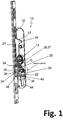
- FIG. 1 shows a perspective view of an actuating gear 10 according to the invention, which comprises a vertically running drive rod 18, which runs in a wing groove formed along a side edge of a lift-slide door (not shown here) and is effective for driving with a lifting element, such as a carriage for lifting that can be moved along a guide rail and lowering the lift-and-slide door, is connected in a drivingly effective manner, so that the lift-and-slide door can be raised or lowered as required by a translational displacement of the drive rod 18.
- a lifting element such as a carriage for lifting that can be moved along a guide rail and lowering the lift-and-slide door
- the actuating gear 10 further comprises a push rod 20 which runs along and parallel to the drive rod 18 and which can be displaced in the vertical direction by means of a self-locking electric motor (not shown here).
- the push rod 20 can be selectively connected to the drive rod 18 by means of a locking assembly 22 so that the same and thus the lifting element can be actuated by means of the electric motor, as is desirable for raising or lowering the lift-slide door. Since the electric motor does not drive the drive rod 18 directly, but acts on the drive rod 18 via the push rod 20, the push rod 20 is also referred to here as a transmission element.
- the drive rod 18 may be due to the coupling with the push rod 20 can no longer be operated manually via the bolt assembly 22.
- the drive-effective coupling of the drive rod 18 with the push rod 20 via the locking assembly 22 can be canceled so that the drive rod 20 can be operated manually .
- the drive rod 18 is drivingly connected via a coupling lever 16 with an essentially ⁇ -shaped design to an input shaft 14 designed as a square nut, which is rotatably mounted in a gear box 12 of the actuating gear 10 and can be coupled to an actuating lever.
- the coupling lever 16 is articulated on the one hand to an eccentric cam 15 of the input shaft 14 and on the other hand to the drive rod 18, so that when the push rod 20 is decoupled, a rotary movement of the input shaft 14 can be converted into a displacement movement of the drive rod 18.
- the head-side flange 17 of the coupling lever 16 at its end facing the drive rod 18 has a notch 19, via which the flange 17 and thus the coupling lever 16 can be positively hooked into a corresponding opening of the drive rod 18 and secured therein, for which purpose the coupling lever 16 or the flange end thereof formed with the notch 19 engages through a longitudinal groove 21 formed in the push rod 20.
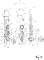
- the bolt assembly 22 will be discussed in more detail, by means of which the drive rod 18 can be selectively coupled to the push rod 20, for which the bolt group 22 in its entirety between a locking position ( Fig. 4 ) and an unlocking position ( Fig. 2 ) can be moved in the horizontal direction or perpendicular to the longitudinal extension of the drive rod 18 and the push rod 20.
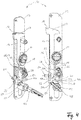
- the locking assembly 22 has a cylindrical bolt 24 which is guided displaceably along a guide rail 26 running parallel to the drive rod 18 and to the push rod 20.
- the guide rail 26 has the shape of a fork with two vertically aligned prongs 27 through which the bolt 24 is guided in the vertical direction. A relative movement between the bolt 24 and the guide rail 26 in the horizontal direction or perpendicular to the drive rod 18, however, is not possible.
- a slide 30 is connected to the guide rail 26, which can also be formed in one piece with the guide rail 26.
- the locking assembly 22 or the assembly of bolt 24, guide rail 26 and slide 30 is guided in a horizontal slot 46 in the rear wall of the gear box 12 in the horizontal direction between its locking position and its unlocking position, for which purpose the guide rail 26 and / or the slide 30 a in the horizontal slot 46 engaging projection (not more precisely recognizable here) may have.
- the bolt assembly 22 is thus displaceable as a whole perpendicular to the drive rod 18 and the push rod 20.
- the bolt 24 engages in an opening 28 in the push rod 20 regardless of whether the locking assembly 22 is in its locking position or in its unlocking position (see FIG Fig. 1 ).
- the drive rod 18 also has a corresponding opening (not visible) into which the bolt 24 engages in a form-fitting manner when the locking assembly 22, starting from the unlocking position according to FIGS Fig. 1 and 2 is moved to the left or towards the drive rod 18 and the push rod 20.
- the bolt 24 thus engages on the one hand in the opening 28 of the push rod 20 and on the other hand in one in the Drive rod 18 forms an opening in a form-fitting manner, whereby the drive rod 18 and the push rod 20 are effectively coupled to one another so that the drive rod 18 and thus a lifting element coupled to it for driving can be actuated for raising and lowering the lifting / sliding door via an electric motor driving the push rod 20 .
- the drive rod 18 can be decoupled from the push rod 20, for which purpose the locking assembly 22 is moved into its unlocked position in order to pull the bolt 24 out of the opening in the drive rod 18.
- the drive rod 18 can thus be actuated purely manually, independently of the push rod 20, via an actuating lever that can be coupled to the square nut 14.
- the adjustment of the locking assembly 22 takes place via a building key 48 or via a cylinder lock which can be inserted into a corresponding opening 24 in the gear box 12.
- the building key 48 has a lock bit 50 (see in particular the illustration on the left in FIG Fig. 2 and 4th ), which as a result of a rotation of the building key 48 comes into contact with the slide 30, so that by rotating the building key 48, the slide 30 and thus the entire bolt assembly 22 can be moved in the horizontal direction between its locking position and its unlocking position.
- a substantially rectangular indentation is formed on the lower edge of the slide 30, by means of which an engagement section 32 is formed, which has two contact surfaces 34a, 34b that are spaced apart perpendicular to the longitudinal extension of the drive rod 18 and facing one another. Therefore, if the building key 38 based on the right illustration of the Fig. 3 is rotated counterclockwise, the locking bit 50 comes into contact with the contact surface 34a, which is supported by the drive rod 18 is turned away, whereby the locking assembly 22 is displaced starting from the unlocked position shown in the horizontal direction to the left in the direction of its locking position, as shown in FIG Fig. 4 is shown.
- the key 48 is based on the Fig. 4 If the locking position shown is rotated clockwise, the locking bit 50 comes into contact with the contact surface 34b of the slide 30 facing the drive rod 18, whereby the locking assembly 22 with continued rotation of the building key 48 clockwise starting from the locking position shown to the right in the horizontal direction into its unlocking position is moved.
- the actuating gear 10 also has a locking part 38 by means of which the bolt assembly 22 can be secured in its respective position.
- the locking part 38 has an essentially L-shaped shape with a horizontally oriented contact section 40, which is located in the movement path of the lock bit 50 of the building key 48.
- the section of the locking part 38 running parallel to the drive rod 18 has laterally protruding projections 54 which engage in vertical slots 52 formed in the gear box 12, see Fig. 1 as well as the left representation of the Fig. 3 , whereby the locking part 38 is guided parallel to the drive rod 18 in the gear box 12. Therefore, when the building key 48 is turned and the lock bit 50 comes into contact with the contact section 40 of the locking part 38, the locking part 38 is displaced upwards parallel to the drive rod 18.
- the slide 30 has a step on its upper edge, which is one of the drive rod 18 facing contact surface 42a forms. Likewise, the slide 30 forms a contact surface 42b along its upper edge which faces away from the drive rod 18.
- the vertically oriented section of the locking part 38 rests against the contact surface 42b of the slide 30, whereby the locking assembly 22 is secured in the locking position of the locking assembly 22 shown. If the building key 48 is turned clockwise in the manner already explained above, the locking bit 50 first comes into contact with the contact section 40 of the locking part 38, whereby this is pushed upward as the building key 48 continues to turn.
- the locking bit 50 first arrives in accordance with the illustration on the left in FIG Fig. 3 with the contact portion 40 of the locking part 38 in contact, whereby this is urged against the biasing action of the spring 36 upwards in the direction of its release position with continued rotation of the key 48. With continued rotation of the building key 48, the lock bit 50 then arrives in accordance with the illustration on the right in FIG Fig.
- the actuating gear according to the invention thus enables an emergency unlocking of a lift-sliding door that can be operated by an electric motor, as can be desirable in the event of a power failure or a defect in the electric motor.
- the actuation gear is designed to be small, which means that small dor dimensions and even a dor dimension of 27.5 mm can be achieved.
Claims (11)
- Mécanisme d'actionnement (10) pour déplacer une tringle d'entraînement (18) d'une fenêtre ou d'une porte, en particulier d'un élément relevable coulissant, tel qu'une porte relevable coulissante ou une fenêtre relevable coulissante, le mécanisme d'actionnement (10) comprenant :- une tringle d'entraînement (18) mobile en translation qui peut être couplée en entraînement à un organe de positionnement, tel qu'un élément de levage, pour relever et abaisser un élément relevable coulissant ;- un arbre d'entrée à commande manuelle (14) couplé en entraînement à la tringle d'entraînement (18) ;- un caisson (12) qui reçoit au moins partiellement l'arbre d'entrée (14) et qui le supporte de façon mobile ;- un élément de transmission (20) pouvant être couplé en entraînement à un moteur électrique ; et- un ensemble de verrouillage (22) mobile entre une position verrouillée et une position déverrouillée ;dans lequel la tringle d'entraînement (18) est couplée en entraînement à l'élément de transmission (20) dans la position verrouillée de l'ensemble de verrouillage (22), tandis que la tringle d'entraînement (18) est découplée de l'élément de transmission (20) dans la position déverrouillée de l'ensemble de verrouillage (22) ;caractérisé en ce quele caisson (12) reçoit également au moins partiellement l'ensemble de verrouillage (22) et le supporte de façon mobile, le caisson (12) présentant une ouverture (44) destinée à recevoir une clé ou une serrure cylindrique pour déplacer l'ensemble de verrouillage (22) et/ou une partie de verrouillage (38) qui est déplaçable entre une position bloquée et une position libérée pour le blocage sélectif de l'ensemble de verrouillage (22) dans sa position déverrouillée et/ou dans sa position verrouillée.
- Mécanisme d'actionnement selon la revendication 1,
caractérisé en ce quel'ensemble de verrouillage (22) comprend un élément de couplage (24) qui est réalisé en particulier sous forme de tenon, et l'élément de transmission (20) comprend une tringle de poussée s'étendant le long de la tringle d'entraînement (18) et présentant une ouverture (28) pour recevoir l'élément de couplage (24), l'élément de couplage (24) s'engageant, dans la position verrouillée du dispositif de verrouillage (22), d'une part dans l'ouverture (28) de la tringle de poussée (20) et d'autre part dans une ouverture formée dans la tringle d'entraînement (18),et il est prévu, en particulier, que l'élément de couplage (24) ne s'engage dans l'ouverture (28) de la tringle de poussée (20) que dans la position déverrouillée de l'ensemble de verrouillage (22). - Mécanisme d'actionnement selon la revendication 1 ou 2,
caractérisé en ce que
l'ensemble de verrouillage (22) comprend en outre un guide (26) le long duquel l'élément de couplage (24) est guidé de façon mobile en translation parallèlement à la tringle d'entraînement (18). - Mécanisme d'actionnement selon l'une au moins des revendications précédentes,
caractérisé en ce quel'ensemble de verrouillage (22) comprend en outre un coulisseau (30) sur lequel est réalisée une portion d'engagement (32) pour l'engagement d'un panneton de fermeture (50) d'une clé, en particulier d'une clé de chantier (48), ou d'une serrure cylindrique,et il est prévu en particulier que la portion d'engagement (32) présente deux surfaces de contact (34a, 34b), espacées l'une de l'autre perpendiculairement à l'extension longitudinale de la tringle d'entraînement (18) et tournées l'une vers l'autre, pour un panneton de fermeture (50). - Mécanisme d'actionnement selon l'une au moins des revendications précédentes,
caractérisé en ce que
la partie de verrouillage (38) comprend une portion de contact (40) pour la mise en contact avec un panneton de fermeture (50) d'une clé, en particulier d'une clé de chantier (48) ou d'une serrure cylindrique. - Mécanisme d'actionnement selon la revendication 5,
caractérisé en ce que
la partie de verrouillage (38) est déplaçable parallèlement à l'extension longitudinale de la tringle d'entraînement (18) entre une position bloquée et une position libérée, le coulisseau (30) de l'ensemble de verrouillage (22) formant une surface d'appui (42a) tournée vers la tringle d'entraînement (18), contre laquelle la partie de verrouillage (38) s'appuie dans sa position bloquée pour bloquer l'ensemble de verrouillage (22) dans sa position déverrouillée, et/ou une surface d'appui (42b) détournée de la tringle d'entraînement (18), contre laquelle la partie de verrouillage (38) s'appuie dans sa position bloquée pour bloquer l'ensemble de verrouillage (22) dans sa position verrouillée. - Mécanisme d'actionnement selon la revendication 5 ou 6,
caractérisé en ce que
la partie de verrouillage (38) est pré-chargée élastiquement en direction de sa position bloquée, en particulier au moyen d'un ressort de précontrainte (36). - Mécanisme d'actionnement selon l'une au moins des revendications précédentes,
caractérisé en ce que
l'ouverture (44) est destinée à recevoir une clé de chantier (48) pour déplacer l'ensemble de verrouillage (22), et il est en particulier prévu que la partie de verrouillage (38) est déplaçable à l'aide d'une clé, d'une clé de chantier (48) ou d'une serrure cylindrique, reçue par l'ouverture (44). - Mécanisme d'actionnement selon la revendication 8,
caractérisé en ce que
l'ouverture (44) est située par rapport à l'ensemble de verrouillage (22), en particulier par rapport à la portion d'engagement du coulisseau (30), de telle sorte que l'ensemble de verrouillage (22) est déplaçable entre sa position verrouillée et sa position déverrouillée au moyen du panneton de fermeture (50) d'une clé, en particulier d'une clé de chantier (48), ou d'une serrure cylindrique qui peut être insérée dans l'ouverture (44) du caisson (12) ; et/ou l'ouverture (44) est située par rapport à la partie de verrouillage (38), en particulier par rapport à la portion de contact (40) de la partie de verrouillage (38), de telle sorte que la partie de verrouillage (38) est déplaçable depuis sa position bloquée jusque dans sa position libérée au moyen du panneton de fermeture (50) d'une clé, en particulier d'une clé de chantier (48), ou d'une serrure cylindrique qui peut être insérée dans l'ouverture du caisson. - Mécanisme d'actionnement selon l'une au moins des revendications précédentes,
caractérisé en ce que
l'arbre d'entrée (14) est réalisé sous forme de douille carrée qui peut être couplée à un levier d'actionnement. - Elément relevable coulissant, en particulier porte relevable coulissante ou fenêtre relevable coulissante, qui est coulissant le long d'un rail de guidage et qui peut être transféré, au moyen d'un élément de levage, d'une position abaissée, dans laquelle l'élément relevable coulissant ne peut pas coulisser, jusque dans une position relevée, dans laquelle l'élément relevable coulissant peut coulisser,
dans lequel l'élément relevable coulissant comprend un mécanisme d'actionnement (10) qui est réalisé selon l'une au moins des revendications précédentes.
Applications Claiming Priority (1)
| Application Number | Priority Date | Filing Date | Title |
|---|---|---|---|
| DE102018119986.4A DE102018119986A1 (de) | 2018-08-16 | 2018-08-16 | Betätigungsgetriebe zum verschieben einer treibstange eines fensters oder einer tür |
Publications (2)
| Publication Number | Publication Date |
|---|---|
| EP3611317A1 EP3611317A1 (fr) | 2020-02-19 |
| EP3611317B1 true EP3611317B1 (fr) | 2021-12-22 |
Family
ID=67438144
Family Applications (1)
| Application Number | Title | Priority Date | Filing Date |
|---|---|---|---|
| EP19187254.8A Active EP3611317B1 (fr) | 2018-08-16 | 2019-07-19 | Mécanisme de commande destiné au déplacement d'une barre d'entrainement d'une fenêtre ou d'une porte |
Country Status (2)
| Country | Link |
|---|---|
| EP (1) | EP3611317B1 (fr) |
| DE (1) | DE102018119986A1 (fr) |
Families Citing this family (2)
| Publication number | Priority date | Publication date | Assignee | Title |
|---|---|---|---|---|
| CN112854945B (zh) * | 2021-02-06 | 2021-12-10 | 哈尔滨贰零贰壹科技有限公司 | 一种自动门 |
| DE102021106475A1 (de) | 2021-03-17 | 2022-09-22 | Maco Technologie Gmbh | Betätigungsgetriebe für ein fenster oder eine tür mit notentriegelungsfunktion |
Family Cites Families (8)
| Publication number | Priority date | Publication date | Assignee | Title |
|---|---|---|---|---|
| DE3640467A1 (de) * | 1986-11-27 | 1988-06-09 | Abs Brandschutz | Verschliesselement zum verschliessen von oeffnungen in schutzraeumen |
| DE10150012A1 (de) * | 2001-10-11 | 2003-04-17 | Siegenia Aubi Kg | Fenster oder Tür mit einem Treibstangenbeschlag |
| DE20312683U1 (de) * | 2003-08-11 | 2003-11-06 | Gretsch Unitas Gmbh | Hebeschiebebeschlag |
| DE10346883A1 (de) * | 2003-10-09 | 2005-05-04 | Winkhaus Fa August | Antriebseinrichtung für einen Treibstangenbeschlag |
| DE102005002180B4 (de) * | 2005-01-17 | 2013-08-08 | Hautau Gmbh | Elektromotorische Vertikal-Steuervorrichtungfür einen Hebe-Schiebeflügel |
| DE102009020939A1 (de) * | 2009-01-12 | 2010-07-22 | Hautau Gmbh | Zungengetriebe zum Verriegeln oder Entriegeln eines Schiebeflügels |
| FR3029234B1 (fr) * | 2014-11-27 | 2018-05-18 | Saint-Gobain Seva | Dispositif de verrouillage-deverrouillage electrique et/ou d'ouverture-fermeture electrique d'une obturation et obturation equipee dudit dispositif. |
| KR101935982B1 (ko) * | 2015-09-02 | 2019-04-03 | (주)엘지하우시스 | 자동/수동 전환구조가 구비된 리프팅 장치 및 이를 포함하는 스마트 창호 |
-
2018
- 2018-08-16 DE DE102018119986.4A patent/DE102018119986A1/de active Pending
-
2019
- 2019-07-19 EP EP19187254.8A patent/EP3611317B1/fr active Active
Non-Patent Citations (1)
| Title |
|---|
| None * |
Also Published As
| Publication number | Publication date |
|---|---|
| EP3611317A1 (fr) | 2020-02-19 |
| DE102018119986A1 (de) | 2020-02-20 |
Similar Documents
| Publication | Publication Date | Title |
|---|---|---|
| EP1932989B1 (fr) | Système de fermeture pour portes, fenêtres ou analogues, en particulier crémone-serrure à fonction d'urgence et de verrouillage à plusieurs points | |
| EP3372757B1 (fr) | Unité de verrouillage pour une installation de verrouillage d'une porte | |
| EP3611317B1 (fr) | Mécanisme de commande destiné au déplacement d'une barre d'entrainement d'une fenêtre ou d'une porte | |
| EP2626491B1 (fr) | Agencement de ferrure | |
| EP1739258B1 (fr) | Serrure de véhicule automobile | |
| EP2820208B1 (fr) | Serrure | |
| DE19652599C2 (de) | Ent- und Verriegelung für eine einen Standflügel und einen Gangflügel aufweisende Tür | |
| EP3299546A1 (fr) | Disque à trancher pour fouillot de panique | |
| EP2339096B1 (fr) | Serrure à crémone dotée d'une fonction anti-panique et d'un verrouillage multiple | |
| DE102015000606A1 (de) | Verriegelungsvorrichtung für einen schwenkbar gelagerten Flügel | |
| EP2738324B1 (fr) | Serrure dotée d'une unité de rotation débloquable | |
| EP3543436B1 (fr) | Contre-serrure pour vantail passif | |
| EP3406832B1 (fr) | Gâche pour une serrure antipanique | |
| DE102013013547B4 (de) | Schloss mit Riegel mit Entriegelungspin | |
| EP2487311A2 (fr) | Serrure de sécurité | |
| DE10011610C1 (de) | Türöffner | |
| DE102007001691B4 (de) | Türöffner | |
| EP3543437B1 (fr) | Dispositif formant serrure pourvu d'une serrure pour une porte à battants mobiles | |
| EP0795665A2 (fr) | Serrure encastrée | |
| EP4060152B1 (fr) | Mécanisme d'actionnement pour une fenêtre ou une porte à fonction de déverrouillage d'urgence | |
| EP3438384A1 (fr) | Serrure | |
| WO2016071202A1 (fr) | Serrure | |
| EP2085543B1 (fr) | Serrure | |
| EP3122964B1 (fr) | Serrure pour porte ou fenêtre | |
| EP1936076B1 (fr) | Serrure anti-panique à verrouillage automatique |
Legal Events
| Date | Code | Title | Description |
|---|---|---|---|
| PUAI | Public reference made under article 153(3) epc to a published international application that has entered the european phase |
Free format text: ORIGINAL CODE: 0009012 |
|
| STAA | Information on the status of an ep patent application or granted ep patent |
Free format text: STATUS: THE APPLICATION HAS BEEN PUBLISHED |
|
| AK | Designated contracting states |
Kind code of ref document: A1 Designated state(s): AL AT BE BG CH CY CZ DE DK EE ES FI FR GB GR HR HU IE IS IT LI LT LU LV MC MK MT NL NO PL PT RO RS SE SI SK SM TR |
|
| AX | Request for extension of the european patent |
Extension state: BA ME |
|
| STAA | Information on the status of an ep patent application or granted ep patent |
Free format text: STATUS: REQUEST FOR EXAMINATION WAS MADE |
|
| 17P | Request for examination filed |
Effective date: 20200214 |
|
| RBV | Designated contracting states (corrected) |
Designated state(s): AL AT BE BG CH CY CZ DE DK EE ES FI FR GB GR HR HU IE IS IT LI LT LU LV MC MK MT NL NO PL PT RO RS SE SI SK SM TR |
|
| STAA | Information on the status of an ep patent application or granted ep patent |
Free format text: STATUS: EXAMINATION IS IN PROGRESS |
|
| STAA | Information on the status of an ep patent application or granted ep patent |
Free format text: STATUS: EXAMINATION IS IN PROGRESS |
|
| 17Q | First examination report despatched |
Effective date: 20200828 |
|
| GRAP | Despatch of communication of intention to grant a patent |
Free format text: ORIGINAL CODE: EPIDOSNIGR1 |
|
| STAA | Information on the status of an ep patent application or granted ep patent |
Free format text: STATUS: GRANT OF PATENT IS INTENDED |
|
| INTG | Intention to grant announced |
Effective date: 20210818 |
|
| GRAS | Grant fee paid |
Free format text: ORIGINAL CODE: EPIDOSNIGR3 |
|
| GRAA | (expected) grant |
Free format text: ORIGINAL CODE: 0009210 |
|
| STAA | Information on the status of an ep patent application or granted ep patent |
Free format text: STATUS: THE PATENT HAS BEEN GRANTED |
|
| AK | Designated contracting states |
Kind code of ref document: B1 Designated state(s): AL AT BE BG CH CY CZ DE DK EE ES FI FR GB GR HR HU IE IS IT LI LT LU LV MC MK MT NL NO PL PT RO RS SE SI SK SM TR |
|
| REG | Reference to a national code |
Ref country code: GB Ref legal event code: FG4D Free format text: NOT ENGLISH |
|
| REG | Reference to a national code |
Ref country code: CH Ref legal event code: EP |
|
| REG | Reference to a national code |
Ref country code: DE Ref legal event code: R096 Ref document number: 502019003044 Country of ref document: DE |
|
| REG | Reference to a national code |
Ref country code: AT Ref legal event code: REF Ref document number: 1457196 Country of ref document: AT Kind code of ref document: T Effective date: 20220115 |
|
| REG | Reference to a national code |
Ref country code: IE Ref legal event code: FG4D Free format text: LANGUAGE OF EP DOCUMENT: GERMAN |
|
| REG | Reference to a national code |
Ref country code: LT Ref legal event code: MG9D |
|
| PG25 | Lapsed in a contracting state [announced via postgrant information from national office to epo] |
Ref country code: RS Free format text: LAPSE BECAUSE OF FAILURE TO SUBMIT A TRANSLATION OF THE DESCRIPTION OR TO PAY THE FEE WITHIN THE PRESCRIBED TIME-LIMIT Effective date: 20211222 Ref country code: LT Free format text: LAPSE BECAUSE OF FAILURE TO SUBMIT A TRANSLATION OF THE DESCRIPTION OR TO PAY THE FEE WITHIN THE PRESCRIBED TIME-LIMIT Effective date: 20211222 Ref country code: FI Free format text: LAPSE BECAUSE OF FAILURE TO SUBMIT A TRANSLATION OF THE DESCRIPTION OR TO PAY THE FEE WITHIN THE PRESCRIBED TIME-LIMIT Effective date: 20211222 Ref country code: BG Free format text: LAPSE BECAUSE OF FAILURE TO SUBMIT A TRANSLATION OF THE DESCRIPTION OR TO PAY THE FEE WITHIN THE PRESCRIBED TIME-LIMIT Effective date: 20220322 |
|
| REG | Reference to a national code |
Ref country code: NL Ref legal event code: MP Effective date: 20211222 |
|
| PG25 | Lapsed in a contracting state [announced via postgrant information from national office to epo] |
Ref country code: SE Free format text: LAPSE BECAUSE OF FAILURE TO SUBMIT A TRANSLATION OF THE DESCRIPTION OR TO PAY THE FEE WITHIN THE PRESCRIBED TIME-LIMIT Effective date: 20211222 Ref country code: NO Free format text: LAPSE BECAUSE OF FAILURE TO SUBMIT A TRANSLATION OF THE DESCRIPTION OR TO PAY THE FEE WITHIN THE PRESCRIBED TIME-LIMIT Effective date: 20220322 Ref country code: LV Free format text: LAPSE BECAUSE OF FAILURE TO SUBMIT A TRANSLATION OF THE DESCRIPTION OR TO PAY THE FEE WITHIN THE PRESCRIBED TIME-LIMIT Effective date: 20211222 Ref country code: HR Free format text: LAPSE BECAUSE OF FAILURE TO SUBMIT A TRANSLATION OF THE DESCRIPTION OR TO PAY THE FEE WITHIN THE PRESCRIBED TIME-LIMIT Effective date: 20211222 Ref country code: GR Free format text: LAPSE BECAUSE OF FAILURE TO SUBMIT A TRANSLATION OF THE DESCRIPTION OR TO PAY THE FEE WITHIN THE PRESCRIBED TIME-LIMIT Effective date: 20220323 |
|
| PG25 | Lapsed in a contracting state [announced via postgrant information from national office to epo] |
Ref country code: NL Free format text: LAPSE BECAUSE OF FAILURE TO SUBMIT A TRANSLATION OF THE DESCRIPTION OR TO PAY THE FEE WITHIN THE PRESCRIBED TIME-LIMIT Effective date: 20211222 |
|
| PG25 | Lapsed in a contracting state [announced via postgrant information from national office to epo] |
Ref country code: SM Free format text: LAPSE BECAUSE OF FAILURE TO SUBMIT A TRANSLATION OF THE DESCRIPTION OR TO PAY THE FEE WITHIN THE PRESCRIBED TIME-LIMIT Effective date: 20211222 Ref country code: SK Free format text: LAPSE BECAUSE OF FAILURE TO SUBMIT A TRANSLATION OF THE DESCRIPTION OR TO PAY THE FEE WITHIN THE PRESCRIBED TIME-LIMIT Effective date: 20211222 Ref country code: RO Free format text: LAPSE BECAUSE OF FAILURE TO SUBMIT A TRANSLATION OF THE DESCRIPTION OR TO PAY THE FEE WITHIN THE PRESCRIBED TIME-LIMIT Effective date: 20211222 Ref country code: PT Free format text: LAPSE BECAUSE OF FAILURE TO SUBMIT A TRANSLATION OF THE DESCRIPTION OR TO PAY THE FEE WITHIN THE PRESCRIBED TIME-LIMIT Effective date: 20220422 Ref country code: ES Free format text: LAPSE BECAUSE OF FAILURE TO SUBMIT A TRANSLATION OF THE DESCRIPTION OR TO PAY THE FEE WITHIN THE PRESCRIBED TIME-LIMIT Effective date: 20211222 Ref country code: EE Free format text: LAPSE BECAUSE OF FAILURE TO SUBMIT A TRANSLATION OF THE DESCRIPTION OR TO PAY THE FEE WITHIN THE PRESCRIBED TIME-LIMIT Effective date: 20211222 Ref country code: CZ Free format text: LAPSE BECAUSE OF FAILURE TO SUBMIT A TRANSLATION OF THE DESCRIPTION OR TO PAY THE FEE WITHIN THE PRESCRIBED TIME-LIMIT Effective date: 20211222 |
|
| PG25 | Lapsed in a contracting state [announced via postgrant information from national office to epo] |
Ref country code: PL Free format text: LAPSE BECAUSE OF FAILURE TO SUBMIT A TRANSLATION OF THE DESCRIPTION OR TO PAY THE FEE WITHIN THE PRESCRIBED TIME-LIMIT Effective date: 20211222 |
|
| REG | Reference to a national code |
Ref country code: DE Ref legal event code: R097 Ref document number: 502019003044 Country of ref document: DE |
|
| PG25 | Lapsed in a contracting state [announced via postgrant information from national office to epo] |
Ref country code: IS Free format text: LAPSE BECAUSE OF FAILURE TO SUBMIT A TRANSLATION OF THE DESCRIPTION OR TO PAY THE FEE WITHIN THE PRESCRIBED TIME-LIMIT Effective date: 20220422 |
|
| PLBE | No opposition filed within time limit |
Free format text: ORIGINAL CODE: 0009261 |
|
| STAA | Information on the status of an ep patent application or granted ep patent |
Free format text: STATUS: NO OPPOSITION FILED WITHIN TIME LIMIT |
|
| PG25 | Lapsed in a contracting state [announced via postgrant information from national office to epo] |
Ref country code: DK Free format text: LAPSE BECAUSE OF FAILURE TO SUBMIT A TRANSLATION OF THE DESCRIPTION OR TO PAY THE FEE WITHIN THE PRESCRIBED TIME-LIMIT Effective date: 20211222 Ref country code: AL Free format text: LAPSE BECAUSE OF FAILURE TO SUBMIT A TRANSLATION OF THE DESCRIPTION OR TO PAY THE FEE WITHIN THE PRESCRIBED TIME-LIMIT Effective date: 20211222 |
|
| 26N | No opposition filed |
Effective date: 20220923 |
|
| PG25 | Lapsed in a contracting state [announced via postgrant information from national office to epo] |
Ref country code: SI Free format text: LAPSE BECAUSE OF FAILURE TO SUBMIT A TRANSLATION OF THE DESCRIPTION OR TO PAY THE FEE WITHIN THE PRESCRIBED TIME-LIMIT Effective date: 20211222 Ref country code: MC Free format text: LAPSE BECAUSE OF FAILURE TO SUBMIT A TRANSLATION OF THE DESCRIPTION OR TO PAY THE FEE WITHIN THE PRESCRIBED TIME-LIMIT Effective date: 20211222 |
|
| REG | Reference to a national code |
Ref country code: CH Ref legal event code: PL |
|
| REG | Reference to a national code |
Ref country code: BE Ref legal event code: MM Effective date: 20220731 |
|
| PG25 | Lapsed in a contracting state [announced via postgrant information from national office to epo] |
Ref country code: LU Free format text: LAPSE BECAUSE OF NON-PAYMENT OF DUE FEES Effective date: 20220719 Ref country code: LI Free format text: LAPSE BECAUSE OF NON-PAYMENT OF DUE FEES Effective date: 20220731 Ref country code: CH Free format text: LAPSE BECAUSE OF NON-PAYMENT OF DUE FEES Effective date: 20220731 |
|
| PG25 | Lapsed in a contracting state [announced via postgrant information from national office to epo] |
Ref country code: BE Free format text: LAPSE BECAUSE OF NON-PAYMENT OF DUE FEES Effective date: 20220731 |
|
| PG25 | Lapsed in a contracting state [announced via postgrant information from national office to epo] |
Ref country code: IE Free format text: LAPSE BECAUSE OF NON-PAYMENT OF DUE FEES Effective date: 20220719 |
|
| PGFP | Annual fee paid to national office [announced via postgrant information from national office to epo] |
Ref country code: IT Payment date: 20230724 Year of fee payment: 5 |
|
| PGFP | Annual fee paid to national office [announced via postgrant information from national office to epo] |
Ref country code: FR Payment date: 20230726 Year of fee payment: 5 Ref country code: DE Payment date: 20230719 Year of fee payment: 5 |
|
| GBPC | Gb: european patent ceased through non-payment of renewal fee |
Effective date: 20230719 |
|
| PG25 | Lapsed in a contracting state [announced via postgrant information from national office to epo] |
Ref country code: HU Free format text: LAPSE BECAUSE OF FAILURE TO SUBMIT A TRANSLATION OF THE DESCRIPTION OR TO PAY THE FEE WITHIN THE PRESCRIBED TIME-LIMIT; INVALID AB INITIO Effective date: 20190719 |
|
| PG25 | Lapsed in a contracting state [announced via postgrant information from national office to epo] |
Ref country code: MK Free format text: LAPSE BECAUSE OF FAILURE TO SUBMIT A TRANSLATION OF THE DESCRIPTION OR TO PAY THE FEE WITHIN THE PRESCRIBED TIME-LIMIT Effective date: 20211222 Ref country code: CY Free format text: LAPSE BECAUSE OF FAILURE TO SUBMIT A TRANSLATION OF THE DESCRIPTION OR TO PAY THE FEE WITHIN THE PRESCRIBED TIME-LIMIT Effective date: 20211222 Ref country code: GB Free format text: LAPSE BECAUSE OF NON-PAYMENT OF DUE FEES Effective date: 20230719 |