EP3609736B1 - Stossabsorbierender sitz mit dämpfungsgliedern - Google Patents
Stossabsorbierender sitz mit dämpfungsgliedern Download PDFInfo
- Publication number
- EP3609736B1 EP3609736B1 EP18717621.9A EP18717621A EP3609736B1 EP 3609736 B1 EP3609736 B1 EP 3609736B1 EP 18717621 A EP18717621 A EP 18717621A EP 3609736 B1 EP3609736 B1 EP 3609736B1
- Authority
- EP
- European Patent Office
- Prior art keywords
- seat
- belt
- damping element
- shaped
- damping
- Prior art date
- Legal status (The legal status is an assumption and is not a legal conclusion. Google has not performed a legal analysis and makes no representation as to the accuracy of the status listed.)
- Active
Links
Images


Classifications
-
- B—PERFORMING OPERATIONS; TRANSPORTING
- B60—VEHICLES IN GENERAL
- B60N—SEATS SPECIALLY ADAPTED FOR VEHICLES; VEHICLE PASSENGER ACCOMMODATION NOT OTHERWISE PROVIDED FOR
- B60N2/00—Seats specially adapted for vehicles; Arrangement or mounting of seats in vehicles
- B60N2/24—Seats specially adapted for vehicles; Arrangement or mounting of seats in vehicles for particular purposes or particular vehicles
-
- B—PERFORMING OPERATIONS; TRANSPORTING
- B60—VEHICLES IN GENERAL
- B60N—SEATS SPECIALLY ADAPTED FOR VEHICLES; VEHICLE PASSENGER ACCOMMODATION NOT OTHERWISE PROVIDED FOR
- B60N2/00—Seats specially adapted for vehicles; Arrangement or mounting of seats in vehicles
- B60N2/24—Seats specially adapted for vehicles; Arrangement or mounting of seats in vehicles for particular purposes or particular vehicles
- B60N2/42—Seats specially adapted for vehicles; Arrangement or mounting of seats in vehicles for particular purposes or particular vehicles the seat constructed to protect the occupant from the effect of abnormal g-forces, e.g. crash or safety seats
- B60N2/4207—Seats specially adapted for vehicles; Arrangement or mounting of seats in vehicles for particular purposes or particular vehicles the seat constructed to protect the occupant from the effect of abnormal g-forces, e.g. crash or safety seats characterised by the direction of the g-forces
- B60N2/4235—Seats specially adapted for vehicles; Arrangement or mounting of seats in vehicles for particular purposes or particular vehicles the seat constructed to protect the occupant from the effect of abnormal g-forces, e.g. crash or safety seats characterised by the direction of the g-forces transversal
-
- B—PERFORMING OPERATIONS; TRANSPORTING
- B60—VEHICLES IN GENERAL
- B60N—SEATS SPECIALLY ADAPTED FOR VEHICLES; VEHICLE PASSENGER ACCOMMODATION NOT OTHERWISE PROVIDED FOR
- B60N2/00—Seats specially adapted for vehicles; Arrangement or mounting of seats in vehicles
- B60N2/24—Seats specially adapted for vehicles; Arrangement or mounting of seats in vehicles for particular purposes or particular vehicles
- B60N2/42—Seats specially adapted for vehicles; Arrangement or mounting of seats in vehicles for particular purposes or particular vehicles the seat constructed to protect the occupant from the effect of abnormal g-forces, e.g. crash or safety seats
- B60N2/4207—Seats specially adapted for vehicles; Arrangement or mounting of seats in vehicles for particular purposes or particular vehicles the seat constructed to protect the occupant from the effect of abnormal g-forces, e.g. crash or safety seats characterised by the direction of the g-forces
- B60N2/4242—Seats specially adapted for vehicles; Arrangement or mounting of seats in vehicles for particular purposes or particular vehicles the seat constructed to protect the occupant from the effect of abnormal g-forces, e.g. crash or safety seats characterised by the direction of the g-forces vertical
-
- B—PERFORMING OPERATIONS; TRANSPORTING
- B60—VEHICLES IN GENERAL
- B60N—SEATS SPECIALLY ADAPTED FOR VEHICLES; VEHICLE PASSENGER ACCOMMODATION NOT OTHERWISE PROVIDED FOR
- B60N2/00—Seats specially adapted for vehicles; Arrangement or mounting of seats in vehicles
- B60N2/24—Seats specially adapted for vehicles; Arrangement or mounting of seats in vehicles for particular purposes or particular vehicles
- B60N2/42—Seats specially adapted for vehicles; Arrangement or mounting of seats in vehicles for particular purposes or particular vehicles the seat constructed to protect the occupant from the effect of abnormal g-forces, e.g. crash or safety seats
- B60N2/427—Seats or parts thereof displaced during a crash
- B60N2/42709—Seats or parts thereof displaced during a crash involving residual deformation or fracture of the structure
-
- B—PERFORMING OPERATIONS; TRANSPORTING
- B60—VEHICLES IN GENERAL
- B60R—VEHICLES, VEHICLE FITTINGS, OR VEHICLE PARTS, NOT OTHERWISE PROVIDED FOR
- B60R22/00—Safety belts or body harnesses in vehicles
- B60R22/12—Construction of belts or harnesses
-
- B—PERFORMING OPERATIONS; TRANSPORTING
- B60—VEHICLES IN GENERAL
- B60R—VEHICLES, VEHICLE FITTINGS, OR VEHICLE PARTS, NOT OTHERWISE PROVIDED FOR
- B60R22/00—Safety belts or body harnesses in vehicles
- B60R22/28—Safety belts or body harnesses in vehicles incorporating energy-absorbing devices
-
- F—MECHANICAL ENGINEERING; LIGHTING; HEATING; WEAPONS; BLASTING
- F41—WEAPONS
- F41H—ARMOUR; ARMOURED TURRETS; ARMOURED OR ARMED VEHICLES; MEANS OF ATTACK OR DEFENCE, e.g. CAMOUFLAGE, IN GENERAL
- F41H7/00—Armoured or armed vehicles
- F41H7/02—Land vehicles with enclosing armour, e.g. tanks
- F41H7/04—Armour construction
- F41H7/046—Shock resilient mounted seats for armoured or fighting vehicles
-
- B—PERFORMING OPERATIONS; TRANSPORTING
- B60—VEHICLES IN GENERAL
- B60R—VEHICLES, VEHICLE FITTINGS, OR VEHICLE PARTS, NOT OTHERWISE PROVIDED FOR
- B60R22/00—Safety belts or body harnesses in vehicles
- B60R22/02—Semi-passive restraint systems, e.g. systems applied or removed automatically but not both ; Manual restraint systems
- B60R2022/027—Four-point seat belt systems, e.g. with the two upper points connected together
-
- B—PERFORMING OPERATIONS; TRANSPORTING
- B60—VEHICLES IN GENERAL
- B60R—VEHICLES, VEHICLE FITTINGS, OR VEHICLE PARTS, NOT OTHERWISE PROVIDED FOR
- B60R22/00—Safety belts or body harnesses in vehicles
- B60R22/28—Safety belts or body harnesses in vehicles incorporating energy-absorbing devices
- B60R2022/283—Safety belts or body harnesses in vehicles incorporating energy-absorbing devices using tearing or scoring of material
-
- B—PERFORMING OPERATIONS; TRANSPORTING
- B60—VEHICLES IN GENERAL
- B60R—VEHICLES, VEHICLE FITTINGS, OR VEHICLE PARTS, NOT OTHERWISE PROVIDED FOR
- B60R22/00—Safety belts or body harnesses in vehicles
- B60R22/28—Safety belts or body harnesses in vehicles incorporating energy-absorbing devices
- B60R2022/286—Safety belts or body harnesses in vehicles incorporating energy-absorbing devices using deformation of material
Definitions
- the invention relates to a seat for a land vehicle which is equipped with at least one damping element.
- a deformation element for protecting a device, in particular a footrest plate in a particularly military vehicle, is known, wherein the deformation element is essentially U-shaped.
- the US 2013/0033056 A1 discloses a cushioning system with belts for a suspended seat. Belts are disclosed which have zones that guide the belt in multiple layers and are held in place by seams. When force is applied, these seams can then tear to compensate for the force.
- the DE 10 2010 020533 A1 discloses a shock-absorbing structural bearing comprising one or more rod-shaped crash elements.
- the rod-shaped crash element(s) each have a predetermined breaking point bridged by at least two tabs.
- the invention is based on the object of providing a seat for a vehicle with which the person is protected from external impacts.
- the seat according to the invention comprises the technical features defined in claim 1.
- an attenuation element which has two points of application in order to introduce pulse-like forces into the attenuation element.
- the damping element also has fastening elements, by means of which the damping element can be fastened.
- the fastening points are preferably arranged at the points of application, so that the force can be applied to the damping element through the fastening elements.
- the fastening elements are designed as tubes. These can then be inserted into existing tubes of a seat and/or the chassis of a vehicle. To fix the pipes, it is then proposed to provide holes in the pipes, which are fixed using screw or plug connections.
- Such a fixation or design as a plug-in pipe system has the advantage of being quick to replace. Accordingly, the damping elements can also be used as spare parts.
- the damping element also has an absorption medium which is able to absorb introduced forces and thus dampen the impulsive force effects.
- Such an absorbent can be a compressible material or an elastic material which returns to its original position after the application of force.
- an additional absorption medium is provided which can also absorb forces and thus contributes to the damping. The damping then occurs through the interaction of the absorption medium and the additional absorption medium.
- the additional absorption medium absorbs the forces acting on it through deformation work. This means that the additional absorption medium is deformed when the force is applied. However, such deformation does not occur under conventional loading and/or force acting on the damping element. Only when a certain force is exceeded is this converted into deformation work. This means that the shape is retained under normal loading of the damping element.
- the damping element has a housing, which can have various shapes. It is proposed to arrange the absorption means inside the housing. The additional absorption means can then be the housing or a part of the housing.
- the parts of the housing intended for deformation are provided with round shapes.
- a heart or cloverleaf shape is therefore preferably proposed for the housing, as these shapes have proven to be particularly suitable for such deformation.
- the damping element is designed as a belt. Due to its physical properties, the belt acts as a Absorbent.
- the belt is preferably provided with elasticity and is made of multiple layers, at least in some areas.
- the additional absorbent consists of seams that connect at least two layers of the belt together.
- the possible deformation work of the additional absorbent takes place by separating the seams when force is applied.
- the seams of the belt are preferably arranged parallel to each other and running across the belt. This creates a number of seams that run parallel to each other and at a distance from each other across the belt. The distances can be the same or different for all seams. These seams are provided at least in some areas on a belt.
- Such a belt can be hinged with its attachment points to a seat and/or the chassis.
- the belt can be arranged in such a way that a person on the seat is protected or movable parts of the seat are dampened.
- the belt can be hinged to the seat and backrest of the seat in order to dampen a foldable seat. If a force is applied from below, for example, the force then acts on the seat. If the seat has a movable or foldable seat, the inertia of the person on the seat can dampen an upward movement of the seat if a damping element is designed as a belt and is hinged to the seat and the seat back. Hinge to the seat and chassis is also conceivable for this purpose.
- the points of application be offset from one another so that they are not aligned. This has the advantage that when force is applied to the points of application, the fastening elements can move in the direction of the damping element without hindering one another.
- the damping elements are designed in such a way that they can be used in a vehicle to cushion a vehicle seat against impact forces acting on the seat. To this end, it is proposed to arrange at least one damping element on the vehicle seat. The movement of a person sitting in the seat can also be dampened by the damping elements.
- the seat can be dampened by arranging at least one damping element between the seat and the vehicle chassis.
- the seat can also be equipped with appropriate belts. A combination of the above arrangements is also conceivable.
- a damping element 1 which has a housing and is approximately heart-shaped when viewed from the side.
- a fastening element 3 is arranged on each side of the heart-shaped damping element 1 at the points of application 2.
- the fastening element 3 is preferably tubular.
- the longitudinal axes of the two tubes are offset in height from one another.
- the cross-sectionally heart-shaped damping element 1 is formed by a sheet metal surrounding the narrower outer sides, to which the tubes arranged, in particular welded on.
- the interior of the heart-shaped damping element 1 is filled with an elastically deformable material which represents the absorption medium.
- the two tube ends that protrude from the heart-shaped damping element 1 connect the seat 10 to its chassis and to a chassis 11 of the vehicle.
- the tubes can also be inserted into existing tubes of the seat and/or the chassis to create a plug connection.
- holes 6 provided for this purpose in the tubes enable the plug connection to be fixed. Such a connection is possible, for example, in Figure I.5 shown.
- the heart-shaped damping element 1 enables the impact energy to be absorbed both by the deformation of the outer heart-shaped
- Deformation is achieved by the fact that the two longitudinal axes of the two fastening tubes are not aligned but are offset in height from one another. This allows the heart-shaped damping element 1 to be pushed into one another in order to reduce the deformation energy and thus significantly weaken the impact effect from the outside, so that the person sitting on the seat 10 is very well protected from this external influence.
- the damping element 1 is integrated in a belt 5.
- the person sitting on the seat 10 can buckle themselves up using such a belt 5, but belts can also be attached to the seat 10 and/or the chassis of a vehicle in order to dampen moving parts of the seat 10.
- the belt 5 is connected in the usual way on the one hand to the seat 10 and on the other hand to the chassis 11 or again to the seat.
- the fastenings of the belts 5 form the fastening elements 3 of the damping element 1 and the ends of the belt 5 form the points of application 2.
- the several seam lines arranged one behind the other and parallel to each other along the length of the belt 5 create a kind of predetermined breaking point, since the seams tear open one after the other as a result of the impact from the outside and thereby reduce the impact energy.
- these multiple seam lines arranged parallel to one another are dimensioned in such a way that they do not normally tear up to the maximum load that the seat 10 may be subjected to.
- Figure II.7 shows a possible seam arrangement for a damping element 1 as a belt 5.
- the seams running parallel to each other and across the belt 5 connect two layers of the belt 5.
- the belt 5 itself is multi-layered in the area of the seams. This can be done by loops that the belt 5 forms in the area of the seams, but the belt 5 can also form the multi-layered area by overlapping several belt pieces.
- seams When force is applied to the belt at the points of application 2, a shear force acts on the seams, which can then be separated and cause the damping of the damping element 1.
- the seams can connect two layers each, as shown, but they can also be continuous through all layers.
- the different seams can be made of different materials, with different tearing behavior.
- the belt is designed in such a way that the damping element is not activated under normal conditions or when force is applied.
- the damping element only becomes active when a certain load limit is exceeded.
- a seat of a vehicle which is connected to the seat 10 by means of the heart-shaped damping element 1 via pipes or the like arranged thereon.
- the damping element 1 is also connected to a chassis 11 of a vehicle (not shown) via pipes or the like.
- the seat 10 shown is equipped with the damping element 1 integrated in the belt 5.
- the seat 10 is arranged on the rear side via several heart-shaped damping elements 1 on the chassis 11 of the vehicle.
- Figure II also shows that the heart-shaped damping element 1 and the damping element 1 integrated in the belt 5 are used as damping elements 1.
- the seat 10 is arranged and fastened via the heart-shaped damping elements 1 not at the rear, but at the side at a suitable location in the vehicle.
- Figure II.2 shows a particularly preferred arrangement of the damping elements 1 designed as a belt 5.
- the belt 5 is hinged to the seat 10 at each of its points of application 2, with one end of the belt 5 being hinged to the backrest of the seat and the other end of the belt 5 to the seat 10. This allows the seat 10 to be dampened when a force is applied to the vehicle if the seat surface of the seat 10 is designed to be movable, e.g. foldable.
- both types of damping elements 1 are also used, whereby here, not a heart-shaped, but a cloverleaf-shaped damping element 1 is used.
- This at least one cloverleaf-shaped damping element 1 is arranged between a chassis 11 of the vehicle, for example a floor plate, and a chassis of the seat 10, for example an underside of the seat surface.
- a cloverleaf-shaped cross-section can also be considered, as shown in Figure III.
- Such a cloverleaf-shaped cross-section of the damping element 1 is used when it is arranged, for example, between the chassis 11 of the vehicle and the chassis of the seat, so that the fastening tubes required for the heart-shaped damping element 1 can be omitted, but do not have to be. Tubes can also be attached to a cloverleaf-shaped damping element 1 in order to arrange and fasten the damping element 1 at its installation location.
- the additional absorption element can be designed as a cover around the absorption element.
- a housing can then also be arranged around the two damping elements. Plug connections at the points of application and/or fastening elements are also possible in order to enable the damping elements to be easily replaced.
Landscapes
- Engineering & Computer Science (AREA)
- Mechanical Engineering (AREA)
- Aviation & Aerospace Engineering (AREA)
- Transportation (AREA)
- Textile Engineering (AREA)
- General Engineering & Computer Science (AREA)
- Seats For Vehicles (AREA)
- Automotive Seat Belt Assembly (AREA)
- Pharmaceuticals Containing Other Organic And Inorganic Compounds (AREA)
- Plural Heterocyclic Compounds (AREA)
Description
- Die Erfindung betrifft einen Sitz für ein Landfahrzeug, der mit zumindest einem Dämpfungsglied ausgerüstet ist.
- Es sind Sitze für Landfahrzeuge, insbesondere für militärische Einsatzzwecke, bekannt, die Dämpfungsglieder aufweisen, um von außen auf das Fahrzeug einwirkende Stöße zu absorbieren und damit den Insassen, die auf diesen Sitzen sitzen, Schutz bieten. Stöße, die von außen auf das Fahrzeug einwirken, sind im Regelfall Stoßwirkungen von explosiven Materialien, wie sie zum Beispiel in Minen, über die das Fahrzeug fährt, Verwendung finden.
- Aus der
DE 10 2008 053 152 A1 ist ein Deformationselement zum Schutz einer Einrichtung, insbesondere einer Fußauflagenplatte in einem insbesondere militärischen Fahrzeug bekannt, wobei das Deformationselement im Wesentlichen U-förmig gestaltet ist. - Die
US 2013/0033056 A1 offenbart dazu ein Dämpfungssystem mit Gurten für einen hängend angeordneten Sitz. Dazu sind Gurte offenbart, welche Zonen aufweisen, welche den Gurt mehrlagig und durch Nähte gehalten führen. Bei Krafteinwirkung können diese Nähte dann zur Kraftkompensation reißen. - Die
DE 10 2010 020533 A1 offenbart eine schockabsorbierende Strukturlagerung, die eines oder mehrere stabförmige Crashelemente umfasst. Das oder die stabförmigen Crashelemente weisen jeweils eine, durch mindestens zwei Laschen überbrückte Sollbruchstelle auf. - Der Erfindung liegt die Aufgabe zu Grunde, einen Sitz für ein Fahrzeug bereitzustellen, mit dem die Person vor äußeren Stoßwirkungen geschützt ist. Der Sitz gemäß der Erfindung umfasst die technischen Merkmale, die im Anspruch 1 definiert sind.
- Erfindungsgemäß wird ein Dämpfungsglied vorgeschlagen, welches zwei Angriffspunkte besitzt, um impulsartig auftretende Kräfte in das Dämpfungsglied einzuleiten.
- Weiterhin besitzt das Dämpfungsglied Befestigungselemente, über welchen das Dämpfungsglied befestigt werden kann. Bevorzugter Weise sind die Befestigungspunkte an den Angriffspunkten angeordnet, so dass die Krafteinwirkung auf das Dämpfungsglied durch die Befestigungselemente geschehen kann.
- In einer besonderen Ausführungsform sind die Befestigungselemente als Rohre ausgeführt. Diese können dann durch Einführen in bestehende Rohre eines Sitzes und/oder des Chassis eines Fahrzeuges angeordnet werden. Zur Fixierung der Rohre wird dann vorgeschlagen, Löcher in en Rohren vorzusehen, welche Mittels Schraub- oder Steckverbindungen fixiert werden.
- Eine solche Fixierung bzw. Ausführung als steckbares Rohrsystem beinhaltet den Vorteil einer schnellen Austauschbarkeit. Dementsprechend können die Dämpfungsglieder auch als Ersatzteile eingesetzt werden.
- Das Dämpfungsglied weist weiterhin ein Absorptionsmittel auf, welches in der Lage ist, eingeleitete Kräfte aufzunehmen und dadurch die impulsartig auftretenden Krafteinwirkungen dämpfen kann.
- Ein solches Absorptionsmittel kann ein komprimierbarer Stoff sein oder ein elastischer Stoff, welcher nach Krafteinwirkung wieder in seine Ausgangslage zurückkehrt.
- Erfindungsgemäß ist ein Zusatzabsorptionsmittel vorgesehen, welches ebenfalls Kräfte aufnehmen kann und somit zur Dämpfung beiträgt. Die Dämpfung geschieht dann durch das Zusammenwirken von Absorptionsmittel und Zusatzabsorptionsmittel.
- Das Zusatzabsorptionsmittel nimmt die einwirkenden Kräfte durch Verformungsarbeit auf. Das bedeutet, dass das Zusatzabsorptionsmittel während der Krafteinwirkung verformt wird. Eine solche Verformung geschieht jedoch nicht bei konventioneller Belastung und/oder Krafteinwirkung auf das Dämpfungsglied. Erst bei Überschreiten einer gewissen Kraft, wird diese in Verformarbeit umgesetzt. Dadurch bleibt die Form bei normaler Belastung des Dämpfungsgliedes erhalten.
- Erfindungsgemäß weist das Dämpfungsglied ein Gehäuse auf, welches verschiedene Formen aufweisen kann. Dabei wird vorgeschlagen, dass Absorptionsmittel innerhalb des Gehäuses anzuordnen. Das Zusatzabsorptionsmittel kann dann das Gehäuse oder ein Teil des Gehäuses sein.
- Um eine Verformung des Gehäuses oder von Teilen des Gehäuses zu unterstützen, sind die zur Verformung bestimmten Teile des Gehäuses mit runden Formen versehen. Bevorzugter Weise wird deshalb für das Gehäuse eine Herz- oder Kleeblattform vorgeschlagen, da diese Formen sich als besonders geeignet für eine entsprechende Verformung erwiesen haben.
- In einer Ausführungsform nach dem Stand der Technik ist das Dämpfungsglied als Gurt ausgeführt. Dabei wirkt der Gurt durch seine physikalischen Eigenschaften als Absorptionsmittel. Bevorzug wird der Gurt hierzu mit einer Elastizität versehen und zumindest bereichsweise mehrlagig ausgeführt. Das Zusatzabsorptionsmittel besteht dabei aus Nähten, welche mindestens zwei Lagen des Gurtes miteinander verbinden.
- Die mögliche Verformarbeit des Zusatzabsorptionsmittels wirkt hierbei durch das Auftrennen der Nähte bei Krafteinwirkung.
- Die Nähte des Gurtes werden bevorzugter Weise parallel zueinander und quer zum Gurt verlaufend angeordnet. Damit entsteht eine Anzahl von parallel zueinander verlaufenden Nähten, welche in einem Abstand zueinander quer zum Gurt verlaufen. Die Abstände können dabei für alle Nähte gleich oder unterschiedlich ausgeführt sein. Diese Nähte sind zumindest bereichsweise an einem Gurt vorgesehen.
- Ein solcher Gurt kann dabei mit seinen Angriffspunkten an einem Sitz und/oder am Chassis angelenkt sein. Der Gurt kann dazu so angeordnet sein, dass eine Person auf dem Sitz geschützt ist oder bewegliche Teile des Sitzes gedämpft werden. Beispielsweise kann der Gurt an der Sitzfläche und der Lehne des Sitzes angelenkt sein, um eine klappbare Sitzfläche zu dämpfen. Bei einer beispielhaften Krafteinwirkung von unten wirkt die Kraft dann auf den Sitz. Wenn der Sitz eine bewegliche oder klappbare Sitzfläche aufweist, kann durch die Trägheit der Person auf dem Sitz eine Aufwärtsbewegung der Sitzfläche gedämpft werden, wenn ein Dämpfungsglied als Gurt ausgeführt ist und an Sitzfläche und der Sitzlehne angelenkt wird. Ebenso ist hierzu eine Anlenkung an Sitzfläche und Chassis denkbar.
- Zur verbesserten Kraftaufnahme wird weiterhin vorgeschlagen, die Angriffspunkte versetzt zueinander anzuordnen, so dass sie nicht fluchten. Das hat den Vorteil, dass bei Krafteinwirkung an den Angriffspunkten die Befestigungselemente sich in Richtung des Dämpfungsglieds bewegen können, ohne sich gegenseitig zu behindern.
- Die Dämpfungsglieder sind so ausgeführt, dass sie in einem Fahrzeug eingesetzt werden können, um einen Fahrzeugsitz gegen Stoßkräfte, die auf den Sitz einwirken, abzudämpfen. Dazu wird vorgeschlagen, mindestens ein Dämpfungsglied am Sitz des Fahrzeugs anzuordnen. Ebenso kann die Bewegung einer im Sitz befindlichen Person durch die Dämpfungsglieder gedämpft werden.
- Der Sitz kann dadurch gedämpft werden, dass mindestens ein Dämpfungsglied zwischen Sitz und Fahrzeugchassis angeordnet ist. Ebenso kann der Sitz auch mit entsprechenden Gurten ausgestattet werden. Auch eine Kombination der vorgenannten Anordnungen ist denkbar.
- Weitere Merkmale der vorliegenden Erfindung zeigen die Figuren:
-
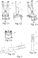
Fig. I : Ein Sitz mit Dämpfungsgliedern und rückseitiger Aufhängung-
Fig. I.1 : Sitz in Vorderansicht -
Fig. I.2 : Sitz in Seitenansicht -
Fig. I.3 : Sitz in perspektivischer Darstellung -
Fig. I.4 : Sitz in Draufsicht -
Fig. I.5 : Dämpfungsglied in Herzform -
Fig. I.6 : Dämpfungsglied als Gurt
-
-
Fig. II : Ein Sitz mit Dämpfungsgliedern und seitlicher Aufhängung-
Fig. II.1 : Sitz in Vorderansicht -
Fig. II.2 : Sitz in Seitenansicht -
Fig. II.3 : Sitz in perspektivischer Darstellung -
Fig. II.4 : Sitz in Draufsicht -
Fig. II 5 : Dämpfungsglied in Herzform -
Fig. II.6 : Dämpfungsglied als Gurt -
Fig. II.7 : Nähte an einem Dämpfungsglied als Gurt
-
-
Fig. III : Ein Sitz mit Dämpfungsgliedern, am Chassis eines Fahrzeugs montiert-
Fig. III.1 : Sitz in Vorderansicht -
Fig. III.2 : Sitz in Seitenansicht -
Fig. III.3 : Sitz in perspektivischer Darstellung -
Fig. III.4 : Sitz in Draufsicht -
Fig. III.5 : Dämpfungsglied in Kleeblattform -
Fig. III.6 : Dämpfungsglied als Gurt -
Fig. III.7 : Dämpfungsglieder zwischen Sitz und Chassis
-
- In
Figur I ist dazu ein Dämpfungsglied 1 vorgesehen, welches ein Gehäuse aufweist und bei seitlicher Betrachtung in etwa herzförmig ausgestaltet ist. An jeder Seite des herzförmigen Dämpfungsgliedes 1 ist ein Befestigungselement 3 an den Angriffspunkten 2 angeordnet. Bevorzugter Weise ist das Befestigungselement 3 rohrförmig gestaltet. Die Längsachsen der beiden Rohre sind höhenversetzt zueinander. Das im Querschnitt herzförmige Dämpfungsglied 1 ist gebildet von einem die schmaleren Außenseiten umgebenden Blech, an dem die Rohre angeordnet, insbesondere angeschweißt sind. Das Innere des herzförmigen Dämpfungsgliedes 1 ist mit einem elastisch verformbaren Material ausgefüllt, welches das Absorptionsmittel darstellt. - Über die beiden Rohrenden, die von dem herzförmigen Dämpfungsglied 1 abstehen, wird der Sitz 10 zum einen mit seinem Chassis und zum anderen mit einem Chassis 11 des Fahrzeuges verbunden. Ebenfalls könne die Rohre in bereits vorhandene Rohre des Sitzes und/oder des Chassis eingeführt werden, um eine Steckverbindung zu erzeugen. Hierzu wird über dafür vorgesehene Löcher 6 in den Rohren eine Fixierung der Steckverbindung ermöglicht. Eine solche Verbindung ist beispielsweise in
Figur I.5 gezeigt. - Kommt es zu einer Stoßeinwirkung auf das Fahrzeug von außen, ermöglicht das herzförmige Dämpfungsglied 1 eine Absorbierung der Stoßenergie sowohl durch die Verformung des äußeren herzförmigen
- Bleches (Zusatzabsorptionsmittel 4), als auch des in seinem Inneren befindlichen elastisch verformbaren Materials (Absorptionsmittel), um die Stoßenergie abzubauen.
- Eine Verformung ist dadurch realisiert, dass die beiden Längsachsen der beiden Befestigungsrohre nicht fluchtend, sondern höhenversetzt zueinander sind. Dies lässt ein Ineinanderschieben des herzförmigen Dämpfungsgliedes 1 zwecks Abbau der Deformationsenergie und damit eine deutliche Abschwächung der von außen einwirkenden Stoßwirkung zu, sodass die auf dem Sitz 10 sitzende Person vor dieser äußeren Beeinflussung sehr gut geschützt wird.
- In einer weiteren Ausgestaltung nach dem Stand der Technik ist das Dämpfungsglied 1 in einem Gurt 5 integriert. Mit einem solchen Gurt 5 kann sich die auf dem Sitz 10 sitzende Person anschnallen, Gurte können aber auch am Sitz 10 und/oder dem Chassis eines Fahrzeugs angelenkt werden, um bewegliche Teile des Sitzes 10 zu dämpfen. Hierbei ist vorgesehen, dass in dem Bereich, in dem der Gurt 5 das Dämpfungsglied 1 bildet, mindestens zwei Lagen des Gurtmaterials im Wesentlichen deckungsgleich übereinander angeordnet sind.
- Quer zu dem Verlauf des Gurtes 5 sind in Abständen zueinander mehrere Nahtlinien zueinander angebracht, die die beiden im Wesentlichen flächendeckend zueinander angeordneten Lagen von Gurtmaterial miteinander verbinden. Im Übrigen ist der Gurt 5 in üblicher Weise einerseits mit dem Sitz 10 und andererseits mit dem Chassis 11 oder nochmals mit dem Sitz verbunden. Die Befestigungen der Gurte 5 bilden hierzu die Befestigungselemente 3 des Dämpfungsgliedes 1 und die Enden des Gurtes 5 bilden die Angriffspunkte 2.
- Die mehreren im Längsverlauf des Gurtes 5 hintereinander und parallel zueinander angeordneten Nahtlinien bewirken eine Art Sollbruchstelle, da die Nähte in Folge der Stoßeinwirkung von außen nacheinander aufreißen und dadurch die Stoßenergie abbauen. Im Normalbetrieb des Fahrzeuges sind diese mehreren parallel zueinander angeordneten Nahtlinien so dimensioniert, dass sie im Normallfall bis zu einer Höchstbelastung, mit der der Sitz 10 belastet werden darf, nicht reißen.
- In Figur II.7 ist eine mögliche Nahtanordnung für ein Dämpfungsglied 1 als Gurt 5 gezeigt. Die parallel zueinander und quer zum Gurt 5 verlaufenden Nähte verbinden hierbei zwei Lagen des Gurtes 5. Der Gurt 5 selbst ist im Bereich der Nähte mehrlagig. Dies kann durch Schlaufen, welche der Gurt 5 im Bereich der Nähte bildet, ausgeführt sein, der Gurt 5 kann aber auch durch überlappendes Übereinanderlegen mehrerer Gurtstücke den Mehrlagigen Bereich bilden.
- Bei Krafteinwirkung auf den Gurt an den Angriffspunkten 2 wirkt dann eine Scherkraft auf die Nähte, welche dadurch aufgetrennt werden können und die Dämpfung des Dämpfungsgliedes 1 bewirken. Die Nähte können, wie gezeigt jeweils zwei Lagen verbinden, aber sie können auch durch alle Lagen durchgehend gestaltet sein. Die unterschiedlichen Nähte können dabei aus unterschiedlichen Materialen gestaltet sein, mit unterschiedlichem Reißverhalten.
- Der Gurt ist so gestaltet, dass unter normalen Bedingungen oder Krafteinwirkungen das Dämpfungsglied nicht aktiviert wird. Nur ab einer gewissen Belastungsgrenze wird das Dämpfungsglied aktiv.
- In
Figur I ist ein Sitz eines Fahrzeuges gezeigt, der mittels des herzförmigen Dämpfungsgliedes 1 über daran angeordnete Rohre oder dergleichen mit dem Sitz 10 verbunden ist. Andererseits ist das Dämpfungsglied 1 ebenfalls über Rohre oder dergleichen mit einem nicht dargestellten Chassis 11 eines Fahrzeuges verbunden. Außerdem ist der dargestellte Sitz 10 mit dem in dem Gurt 5 integrierten Dämpfungsglied 1 ausgerüstet. In dieser Darstellung ist der Sitz 10 rückseitig über mehrere herzförmige Dämpfungsglieder 1 an dem Chassis 11 des Fahrzeuges angeordnet. - In Figur II ist ebenfalls gezeigt, dass als Dämpfungsglieder 1 das herzförmige Dämpfungsglied 1 sowie das in dem Gurt 5 integrierte Dämpfungsglied 1 zur Anwendung kommen. Allerdings ist bei dieser Ausgestaltung der Sitz 10 über die herzförmigen Dämpfungsglieder 1 nicht rückseitig, sondern seitlich an geeigneter Stelle im Fahrzeug angeordnet und befestigt.
- Figur II.2 zeigt eine besonders bevorzugte Anordnung der als Gurt 5 ausgeführten Dämpfungsglieder 1. Dabei wird der Gurt 5 mit seinen Angriffspunkten 2 jeweils am Sitz 10 angelenkt, wobei ein Ende des Gurtes 5 an der Lehne des Sitzes angelenkt wird und das andere Ende des Gurtes 5 am Sitz 10. Dadurch kann der Sitz 10 bei Krafteinwirkung auf das Fahrzeug gedämpft werden, wenn die Sitzfläche des Sitzes 10 beweglich, z.b. klappbar, gestaltet ist.
- In Figur III kommen ebenfalls beide Arten von Dämpfungsgliedern 1 zur Anwendung, wobei hier kein herzförmiges, sondern ein kleeblattförmiges Dämpfungsglied 1 eingesetzt wird. Dieses zumindest eine kleeblattförmige Dämpfungsglied 1 ist angeordnet zwischen einem Chassis 11 des Fahrzeuges, beispielsweise einer Bodenplatte, und einem Chassis des Sitzes 10, beispielsweise einer Unterseite der Sitzfläche.
- Bei allen Figuren ist gezeigt, dass sowohl das herz- beziehungsweise kleeblattförmige Dämpfungsglied 1 und das in den Gurt 5 integrierte Dämpfungsglied 1 zur Anwendung kommen. Dadurch erhöht sich die Schutzwirkung deutlich. Andererseits ist es denkbar, dass bei den drei gezeigten Darstellungsformen des Sitzes 10 auch nur das herzförmige, nur das kleeblattförmige oder nur das in den Gurt 5 integrierte Dämpfungsglied 1 zum Einsatz kommen kann. Auch die Kombination zumindest eines herzförmigen mit zumindest einem kleeblattförmigen Dämpfungsglied 1 kann in Betracht kommen.
- Alternativ zu dem vorstehend beschriebenen herzförmigen Querschnitt des Dämpfungsgliedes 1 kommt, wie in Figur III gezeigt, auch ein kleeblattförmiger Querschnitt in Betracht. Ein solcher kleeblattförmiger Querschnitt des Dämpfungsgliedes 1 findet dann Anwendung, wenn es zum Beispiel zwischen dem Chassis 11 des Fahrzeuges und dem Chassis des Sitzes angeordnet ist, sodass die bei dem herzförmigen Dämpfungsglied 1 erforderlichen Befestigungsrohre entfallen können, aber nicht müssen. Auch bei einem kleeblattförmigen Dämpfungsglied 1 können Rohre befestigt sein, um damit das Dämpfungsglied 1 an seinem Einbauort anzuordnen und zu befestigen.
- Die Erfindung ist nicht auf die vorgenannten Merkmale beschränkt. Vielmehr sind weitere Ausgestaltungen möglich, solange sie zum Schutzumfang gehören, der durch die Ansprüche definiert ist. So kann das Zusatzabsorptionselement als Hülle um das Absorptionselement ausgestaltet sein. Ein Gehäuse kann dann zusätzlich um die beiden dämpfenden Elemente angeordnet sein. Ebenfalls sind Steckverbindungen an den Angriffspunkten und/oder Befestigungselemente möglich, um ein einfaches Auswechseln der Dämpfungsglieder zu ermöglichen.
-
- 1
- Dämpfungsglied
- 2
- Angriffspunkt
- 3
- Befestigungselement
- 4
- Zusatzabsorptionsmittel
- 5
- Gurt
- 6
- Loch
- 10
- Sitz
- 11
- Chassis
Claims (8)
- Sitz (10) für ein Landfahrzeug,- wobei der Sitz (10) mindestens ein Dämpfungsglied (1) umfasst,- wobei das Dämpfungsglied (1) mindestens zwei Angriffspunkte (2) sowie Befestigungselemente (3) aufweist,- wobei das Dämpfungsglied (1) ein Absorptionsmittel aufweist,- wobei ein Zusatzabsorptionsmittel (4) vorgesehen ist, welches zusammen mit dem Absorptionsmittel eine Stoßabsorption bewirkt,- wobei die Angriffspunkte (2) versetzt zueinander angeordnet sind, und- wobei die Angriffspunkte (2) so angeordnet sind, so dass sie nicht miteinander fluchten,- wobei das Dämpfungsglied (1) ein Gehäuse aufweist, dadurch gekennzeichnet, dass der Sitz (10) mindestens einen Gurt (5) umfasst und das Dämpfungsglied (1) in den Gurt (5) integriert ist.
- Sitz (10) nach Anspruch 1, dadurch gekennzeichnet, dass- das Absorptionsmittel innerhalb des Dämpfungsglieds (1) angeordnet ist.
- Sitz (10) nach Anspruch 1 oder 2, dadurch gekennzeichnet, dass- das Zusatzabsorptionsmittel (4) aus verformbaren Teilen des Gehäuses besteht.
- Sitz (10) nach einem der Ansprüche 1 bis 3, dadurch gekennzeichnet, dass- die Befestigungselemente (3) an den Angriffspunkten (2) angeordnet sind.
- Sitz (10) nach einem der Ansprüche 1 bis 4, dadurch gekennzeichnet, dass- die Befestigungselemente (3) zur Befestigung an Rohren ausgeführt sind.
- Sitz (10) nach einem der Ansprüche 1 bis 5, dadurch gekennzeichnet, dass- das Absorptionsmittel aus einem elastisch verformbaren Material besteht.
- Sitz (10) nach einem der Ansprüche 1 bis 6, dadurch gekennzeichnet, dass- das Dämpfungsglied herzförmig oder kleeblattförmig gestaltet ist.
- Sitz (10) nach einem der Ansprüche 1 bis 7, dadurch gekennzeichnet, dass- das Dämpfungsglied (1) zwischen Sitz (10) und einem Chassis (11) des Landfahrzeugs angeordnet werden kann.
Applications Claiming Priority (2)
| Application Number | Priority Date | Filing Date | Title |
|---|---|---|---|
| DE102017108072 | 2017-04-13 | ||
| PCT/EP2018/059600 WO2018189396A1 (de) | 2017-04-13 | 2018-04-13 | Stossabsorbierender sitz mit dämpfungsgliedern |
Publications (3)
| Publication Number | Publication Date |
|---|---|
| EP3609736A1 EP3609736A1 (de) | 2020-02-19 |
| EP3609736C0 EP3609736C0 (de) | 2025-01-08 |
| EP3609736B1 true EP3609736B1 (de) | 2025-01-08 |
Family
ID=61972151
Family Applications (1)
| Application Number | Title | Priority Date | Filing Date |
|---|---|---|---|
| EP18717621.9A Active EP3609736B1 (de) | 2017-04-13 | 2018-04-13 | Stossabsorbierender sitz mit dämpfungsgliedern |
Country Status (7)
| Country | Link |
|---|---|
| US (1) | US11890976B2 (de) |
| EP (1) | EP3609736B1 (de) |
| AU (1) | AU2018252201B2 (de) |
| CA (1) | CA3076209A1 (de) |
| DE (1) | DE102018108872A1 (de) |
| SG (1) | SG11201909922SA (de) |
| WO (1) | WO2018189396A1 (de) |
Families Citing this family (3)
| Publication number | Priority date | Publication date | Assignee | Title |
|---|---|---|---|---|
| AU2018250922A1 (en) * | 2017-04-13 | 2019-11-21 | Rheinmetall Protection Systems Gmbh | Shock-absorbing seat having wall-mounted damping members |
| US10668890B2 (en) * | 2018-01-18 | 2020-06-02 | Winfield Rock | Automobile seat restraint system and method |
| IT202200000785A1 (it) * | 2022-01-19 | 2023-07-19 | Ferrari Spa | Cintura di sicurezza a quattro punti e relativo veicolo stradale |
Family Cites Families (14)
| Publication number | Priority date | Publication date | Assignee | Title |
|---|---|---|---|---|
| DE1243030B (de) * | 1963-03-07 | 1967-06-22 | Continental Gummi Werke Ag | Elastische Lagerung des oberen Endes eines Federbeines fuer lenkbare Fahrzeugraeder mit einem Gummikoerper |
| US3986748A (en) * | 1973-05-18 | 1976-10-19 | Emil Magnuson | Tractor chair cushion device |
| NL1002799C2 (nl) | 1996-04-04 | 1997-10-07 | Michel Jozef Willem Coenen | Verbindingsdeel. |
| AT500225B1 (de) * | 2004-05-06 | 2009-06-15 | Steyr Daimler Puch Ag | Sitz für ein gepanzertes fahrzeug |
| IL182081A (en) * | 2007-03-21 | 2013-08-29 | Plasan Sasa Ltd | Method and device for hanging an item in a vehicle |
| DE102008053152B4 (de) | 2008-10-24 | 2012-05-31 | Krauss-Maffei Wegmann Gmbh & Co. Kg | Deformationselement zum Schutz einer Einrichtung, insbesondere einer Fußauflagenplatte, in einem insbesondere militärischen Fahrzeug |
| DE102010020533B4 (de) | 2010-05-14 | 2012-01-19 | Eads Deutschland Gmbh | Schockabsorbierende Strukturlagerung |
| US20120200128A1 (en) * | 2011-02-04 | 2012-08-09 | Gustavo Soliz | Safety Seat with Incorporated Mechanical Damping Element and Suspended on a Textile Support Frame |
| US20130033056A1 (en) * | 2011-08-05 | 2013-02-07 | Tunis Iii George C | Energy absorbing system for blast mitigation of support elements such as suspended seats or stretchers in military vehicles |
| DE102011053156B4 (de) * | 2011-08-31 | 2017-02-02 | Schroth Safety Products Gmbh | Sicherheitssitz |
| DE102012103036A1 (de) | 2012-04-10 | 2013-10-10 | Krauss-Maffei Wegmann Gmbh & Co. Kg | Gehäuse, insbesondere gegen Detonationswirkung geschütztes Fahrzeuggehäuse |
| GB2504982B (en) * | 2012-08-16 | 2015-06-17 | Wolfstone Technology Ltd | A shock attenuating mounting |
| AU2018250922A1 (en) * | 2017-04-13 | 2019-11-21 | Rheinmetall Protection Systems Gmbh | Shock-absorbing seat having wall-mounted damping members |
| EP3609735B1 (de) * | 2017-04-13 | 2022-05-18 | Rheinmetall Protection Systems GmbH | Stossabsorbierender sitz mit boden- oder deckenmontierten dämpfungsgliedern |
-
2018
- 2018-04-13 US US16/605,078 patent/US11890976B2/en active Active
- 2018-04-13 SG SG11201909922S patent/SG11201909922SA/en unknown
- 2018-04-13 WO PCT/EP2018/059600 patent/WO2018189396A1/de not_active Ceased
- 2018-04-13 DE DE102018108872.8A patent/DE102018108872A1/de not_active Withdrawn
- 2018-04-13 AU AU2018252201A patent/AU2018252201B2/en not_active Ceased
- 2018-04-13 CA CA3076209A patent/CA3076209A1/en active Pending
- 2018-04-13 EP EP18717621.9A patent/EP3609736B1/de active Active
Also Published As
| Publication number | Publication date |
|---|---|
| AU2018252201B2 (en) | 2023-08-24 |
| AU2018252201A1 (en) | 2019-11-21 |
| CA3076209A1 (en) | 2018-10-18 |
| EP3609736C0 (de) | 2025-01-08 |
| EP3609736A1 (de) | 2020-02-19 |
| US20200391630A1 (en) | 2020-12-17 |
| SG11201909922SA (en) | 2019-11-28 |
| DE102018108872A1 (de) | 2018-10-18 |
| US11890976B2 (en) | 2024-02-06 |
| WO2018189396A1 (de) | 2018-10-18 |
Similar Documents
| Publication | Publication Date | Title |
|---|---|---|
| DE69706597T2 (de) | Schienenfahrzeug mit einem Fahrerstand, der eine energieaufnehmende Struktur mit progressiver Verformung aufweist | |
| DE3011906C2 (de) | Stoßfänger für Fahrzeuge | |
| DE69319245T2 (de) | Druckenergieabsorptionsmechanismus für eine vorrichtung zum verriegeln einer verstellbaren rückenlehne | |
| DE1780008A1 (de) | Anordnung eines Sitzes in einem Fahrzeug | |
| DE1963334B2 (de) | Energieaufnahmeglied | |
| DE102010060974A1 (de) | Centerairbagkissen und Centerairbagmodul, das dieses aufweist | |
| EP2955056B1 (de) | Dämpfungsmodul für einen fahrzeugsitz | |
| EP3609736B1 (de) | Stossabsorbierender sitz mit dämpfungsgliedern | |
| DE1963335C3 (de) | Stoßdämpfungseinrichtung für Fahrzeuge | |
| DE102016120452B4 (de) | Seitentürverkleidung für ein Fahrzeug | |
| DE102007006013A1 (de) | Sicherheitssitz mit einer zusätzlichen verstellbaren Rückenlehne | |
| DE102014207752A1 (de) | Fahrzeugwandung und Fahrzeug mit einer Fahrzeugwandung | |
| EP4242058A2 (de) | Kindersitz zur anbringung auf einem kraftfahrzeugsitz | |
| DE102014009615B4 (de) | Kraftwagenbug | |
| DE102020203470A1 (de) | Energie absorbierende rückhaltesysteme wie etwa für die verwendung mit kindersitzen | |
| DE102017201356A1 (de) | Sitzträger für einen Fahrzeugsitz | |
| DE60206247T2 (de) | Befestigungshaken für ein Sicherheitsnetz eines Kraftfahrzeuges | |
| EP3609735B1 (de) | Stossabsorbierender sitz mit boden- oder deckenmontierten dämpfungsgliedern | |
| DE10236437A1 (de) | Vorrichtung zum Blockieren eines Bremspedals eines Fahrzeuges | |
| EP0843626B1 (de) | Fahrzeugsitz mit einem dämpfelement | |
| DE19939990A1 (de) | Seitenaufpralldämpfeinrichtung für ein Fahrzeug | |
| DE2152104A1 (de) | Sitz, insbesondere fuer kraftfahrzeuge | |
| DE102016009455A1 (de) | Baugruppe für ein Kraftfahrzeug und Kraftfahrzeug mit einer Baugruppe | |
| DE102018108876A1 (de) | Stoßabsorbierender Sitz mit wandmontierten Dämpfungsgliedern | |
| DE102009047040A1 (de) | Zelle, welche Impakt-gefährdet oder Crash-gefährdet ist, und Fahrzeug |
Legal Events
| Date | Code | Title | Description |
|---|---|---|---|
| STAA | Information on the status of an ep patent application or granted ep patent |
Free format text: STATUS: UNKNOWN |
|
| STAA | Information on the status of an ep patent application or granted ep patent |
Free format text: STATUS: THE INTERNATIONAL PUBLICATION HAS BEEN MADE |
|
| PUAI | Public reference made under article 153(3) epc to a published international application that has entered the european phase |
Free format text: ORIGINAL CODE: 0009012 |
|
| STAA | Information on the status of an ep patent application or granted ep patent |
Free format text: STATUS: REQUEST FOR EXAMINATION WAS MADE |
|
| 17P | Request for examination filed |
Effective date: 20191022 |
|
| AK | Designated contracting states |
Kind code of ref document: A1 Designated state(s): AL AT BE BG CH CY CZ DE DK EE ES FI FR GB GR HR HU IE IS IT LI LT LU LV MC MK MT NL NO PL PT RO RS SE SI SK SM TR |
|
| AX | Request for extension of the european patent |
Extension state: BA ME |
|
| RIN1 | Information on inventor provided before grant (corrected) |
Inventor name: NEULING, RENE Inventor name: BUDER, FRANCOIS Inventor name: INDEN, MICHAEL |
|
| RAP1 | Party data changed (applicant data changed or rights of an application transferred) |
Owner name: RHEINMETALL PROTECTION SYSTEMS GMBH |
|
| DAV | Request for validation of the european patent (deleted) | ||
| DAX | Request for extension of the european patent (deleted) | ||
| STAA | Information on the status of an ep patent application or granted ep patent |
Free format text: STATUS: EXAMINATION IS IN PROGRESS |
|
| 17Q | First examination report despatched |
Effective date: 20210202 |
|
| GRAP | Despatch of communication of intention to grant a patent |
Free format text: ORIGINAL CODE: EPIDOSNIGR1 |
|
| STAA | Information on the status of an ep patent application or granted ep patent |
Free format text: STATUS: GRANT OF PATENT IS INTENDED |
|
| INTG | Intention to grant announced |
Effective date: 20241023 |
|
| GRAS | Grant fee paid |
Free format text: ORIGINAL CODE: EPIDOSNIGR3 |
|
| GRAA | (expected) grant |
Free format text: ORIGINAL CODE: 0009210 |
|
| STAA | Information on the status of an ep patent application or granted ep patent |
Free format text: STATUS: THE PATENT HAS BEEN GRANTED |
|
| AK | Designated contracting states |
Kind code of ref document: B1 Designated state(s): AL AT BE BG CH CY CZ DE DK EE ES FI FR GB GR HR HU IE IS IT LI LT LU LV MC MK MT NL NO PL PT RO RS SE SI SK SM TR |
|
| REG | Reference to a national code |
Ref country code: GB Ref legal event code: FG4D Free format text: NOT ENGLISH |
|
| REG | Reference to a national code |
Ref country code: CH Ref legal event code: EP |
|
| REG | Reference to a national code |
Ref country code: DE Ref legal event code: R096 Ref document number: 502018015485 Country of ref document: DE |
|
| REG | Reference to a national code |
Ref country code: IE Ref legal event code: FG4D Free format text: LANGUAGE OF EP DOCUMENT: GERMAN |
|
| U01 | Request for unitary effect filed |
Effective date: 20250114 |
|
| U07 | Unitary effect registered |
Designated state(s): AT BE BG DE DK EE FI FR IT LT LU LV MT NL PT RO SE SI Effective date: 20250120 |
|
| U20 | Renewal fee for the european patent with unitary effect paid |
Year of fee payment: 8 Effective date: 20250425 |
|
| PG25 | Lapsed in a contracting state [announced via postgrant information from national office to epo] |
Ref country code: RS Free format text: LAPSE BECAUSE OF FAILURE TO SUBMIT A TRANSLATION OF THE DESCRIPTION OR TO PAY THE FEE WITHIN THE PRESCRIBED TIME-LIMIT Effective date: 20250408 |
|
| PG25 | Lapsed in a contracting state [announced via postgrant information from national office to epo] |
Ref country code: PL Free format text: LAPSE BECAUSE OF FAILURE TO SUBMIT A TRANSLATION OF THE DESCRIPTION OR TO PAY THE FEE WITHIN THE PRESCRIBED TIME-LIMIT Effective date: 20250108 |
|
| PG25 | Lapsed in a contracting state [announced via postgrant information from national office to epo] |
Ref country code: ES Free format text: LAPSE BECAUSE OF FAILURE TO SUBMIT A TRANSLATION OF THE DESCRIPTION OR TO PAY THE FEE WITHIN THE PRESCRIBED TIME-LIMIT Effective date: 20250108 |
|
| PG25 | Lapsed in a contracting state [announced via postgrant information from national office to epo] |
Ref country code: NO Free format text: LAPSE BECAUSE OF FAILURE TO SUBMIT A TRANSLATION OF THE DESCRIPTION OR TO PAY THE FEE WITHIN THE PRESCRIBED TIME-LIMIT Effective date: 20250408 Ref country code: IS Free format text: LAPSE BECAUSE OF FAILURE TO SUBMIT A TRANSLATION OF THE DESCRIPTION OR TO PAY THE FEE WITHIN THE PRESCRIBED TIME-LIMIT Effective date: 20250508 |
|
| PG25 | Lapsed in a contracting state [announced via postgrant information from national office to epo] |
Ref country code: HR Free format text: LAPSE BECAUSE OF FAILURE TO SUBMIT A TRANSLATION OF THE DESCRIPTION OR TO PAY THE FEE WITHIN THE PRESCRIBED TIME-LIMIT Effective date: 20250108 |
|
| PG25 | Lapsed in a contracting state [announced via postgrant information from national office to epo] |
Ref country code: GR Free format text: LAPSE BECAUSE OF FAILURE TO SUBMIT A TRANSLATION OF THE DESCRIPTION OR TO PAY THE FEE WITHIN THE PRESCRIBED TIME-LIMIT Effective date: 20250409 |
|
| PGFP | Annual fee paid to national office [announced via postgrant information from national office to epo] |
Ref country code: TR Payment date: 20250407 Year of fee payment: 8 |
|
| PG25 | Lapsed in a contracting state [announced via postgrant information from national office to epo] |
Ref country code: SM Free format text: LAPSE BECAUSE OF FAILURE TO SUBMIT A TRANSLATION OF THE DESCRIPTION OR TO PAY THE FEE WITHIN THE PRESCRIBED TIME-LIMIT Effective date: 20250108 |
|
| PG25 | Lapsed in a contracting state [announced via postgrant information from national office to epo] |
Ref country code: CZ Free format text: LAPSE BECAUSE OF FAILURE TO SUBMIT A TRANSLATION OF THE DESCRIPTION OR TO PAY THE FEE WITHIN THE PRESCRIBED TIME-LIMIT Effective date: 20250108 |
|
| PG25 | Lapsed in a contracting state [announced via postgrant information from national office to epo] |
Ref country code: SK Free format text: LAPSE BECAUSE OF FAILURE TO SUBMIT A TRANSLATION OF THE DESCRIPTION OR TO PAY THE FEE WITHIN THE PRESCRIBED TIME-LIMIT Effective date: 20250108 |
|
| PLBE | No opposition filed within time limit |
Free format text: ORIGINAL CODE: 0009261 |
|
| STAA | Information on the status of an ep patent application or granted ep patent |
Free format text: STATUS: NO OPPOSITION FILED WITHIN TIME LIMIT |
|
| REG | Reference to a national code |
Ref country code: CH Ref legal event code: L10 Free format text: ST27 STATUS EVENT CODE: U-0-0-L10-L00 (AS PROVIDED BY THE NATIONAL OFFICE) Effective date: 20251119 |
|
| REG | Reference to a national code |
Ref country code: CH Ref legal event code: H13 Free format text: ST27 STATUS EVENT CODE: U-0-0-H10-H13 (AS PROVIDED BY THE NATIONAL OFFICE) Effective date: 20251125 |
|
| 26N | No opposition filed |
Effective date: 20251009 |
|
| PG25 | Lapsed in a contracting state [announced via postgrant information from national office to epo] |
Ref country code: MC Free format text: LAPSE BECAUSE OF FAILURE TO SUBMIT A TRANSLATION OF THE DESCRIPTION OR TO PAY THE FEE WITHIN THE PRESCRIBED TIME-LIMIT Effective date: 20250108 |
|
| GBPC | Gb: european patent ceased through non-payment of renewal fee |
Effective date: 20250413 |
|
| PG25 | Lapsed in a contracting state [announced via postgrant information from national office to epo] |
Ref country code: GB Free format text: LAPSE BECAUSE OF NON-PAYMENT OF DUE FEES Effective date: 20250413 |
|
| PG25 | Lapsed in a contracting state [announced via postgrant information from national office to epo] |
Ref country code: CH Free format text: LAPSE BECAUSE OF NON-PAYMENT OF DUE FEES Effective date: 20250430 |
|
| PG25 | Lapsed in a contracting state [announced via postgrant information from national office to epo] |
Ref country code: IE Free format text: LAPSE BECAUSE OF NON-PAYMENT OF DUE FEES Effective date: 20250413 |