EP3609558B1 - Variabler indikator für nadel eines sicherheitspens - Google Patents
Variabler indikator für nadel eines sicherheitspens Download PDFInfo
- Publication number
- EP3609558B1 EP3609558B1 EP18784982.3A EP18784982A EP3609558B1 EP 3609558 B1 EP3609558 B1 EP 3609558B1 EP 18784982 A EP18784982 A EP 18784982A EP 3609558 B1 EP3609558 B1 EP 3609558B1
- Authority
- EP
- European Patent Office
- Prior art keywords
- hub
- sleeve
- safety pen
- needle
- shield
- Prior art date
- Legal status (The legal status is an assumption and is not a legal conclusion. Google has not performed a legal analysis and makes no representation as to the accuracy of the status listed.)
- Active
Links
Images




Classifications
-
- A—HUMAN NECESSITIES
- A61—MEDICAL OR VETERINARY SCIENCE; HYGIENE
- A61M—DEVICES FOR INTRODUCING MEDIA INTO, OR ONTO, THE BODY; DEVICES FOR TRANSDUCING BODY MEDIA OR FOR TAKING MEDIA FROM THE BODY; DEVICES FOR PRODUCING OR ENDING SLEEP OR STUPOR
- A61M5/00—Devices for bringing media into the body in a subcutaneous, intra-vascular or intramuscular way; Accessories therefor, e.g. filling or cleaning devices, arm-rests
- A61M5/178—Syringes
- A61M5/31—Details
- A61M5/32—Needles; Details of needles pertaining to their connection with syringe or hub; Accessories for bringing the needle into, or holding the needle on, the body; Devices for protection of needles
- A61M5/3202—Devices for protection of the needle before use, e.g. caps
-
- A—HUMAN NECESSITIES
- A61—MEDICAL OR VETERINARY SCIENCE; HYGIENE
- A61M—DEVICES FOR INTRODUCING MEDIA INTO, OR ONTO, THE BODY; DEVICES FOR TRANSDUCING BODY MEDIA OR FOR TAKING MEDIA FROM THE BODY; DEVICES FOR PRODUCING OR ENDING SLEEP OR STUPOR
- A61M5/00—Devices for bringing media into the body in a subcutaneous, intra-vascular or intramuscular way; Accessories therefor, e.g. filling or cleaning devices, arm-rests
- A61M5/178—Syringes
- A61M5/20—Automatic syringes, e.g. with automatically actuated piston rod, with automatic needle injection, filling automatically
-
- A—HUMAN NECESSITIES
- A61—MEDICAL OR VETERINARY SCIENCE; HYGIENE
- A61M—DEVICES FOR INTRODUCING MEDIA INTO, OR ONTO, THE BODY; DEVICES FOR TRANSDUCING BODY MEDIA OR FOR TAKING MEDIA FROM THE BODY; DEVICES FOR PRODUCING OR ENDING SLEEP OR STUPOR
- A61M5/00—Devices for bringing media into the body in a subcutaneous, intra-vascular or intramuscular way; Accessories therefor, e.g. filling or cleaning devices, arm-rests
- A61M5/178—Syringes
- A61M5/24—Ampoule syringes, i.e. syringes with needle for use in combination with replaceable ampoules or carpules, e.g. automatic
-
- A—HUMAN NECESSITIES
- A61—MEDICAL OR VETERINARY SCIENCE; HYGIENE
- A61M—DEVICES FOR INTRODUCING MEDIA INTO, OR ONTO, THE BODY; DEVICES FOR TRANSDUCING BODY MEDIA OR FOR TAKING MEDIA FROM THE BODY; DEVICES FOR PRODUCING OR ENDING SLEEP OR STUPOR
- A61M5/00—Devices for bringing media into the body in a subcutaneous, intra-vascular or intramuscular way; Accessories therefor, e.g. filling or cleaning devices, arm-rests
- A61M5/178—Syringes
- A61M5/31—Details
- A61M5/32—Needles; Details of needles pertaining to their connection with syringe or hub; Accessories for bringing the needle into, or holding the needle on, the body; Devices for protection of needles
-
- A—HUMAN NECESSITIES
- A61—MEDICAL OR VETERINARY SCIENCE; HYGIENE
- A61M—DEVICES FOR INTRODUCING MEDIA INTO, OR ONTO, THE BODY; DEVICES FOR TRANSDUCING BODY MEDIA OR FOR TAKING MEDIA FROM THE BODY; DEVICES FOR PRODUCING OR ENDING SLEEP OR STUPOR
- A61M5/00—Devices for bringing media into the body in a subcutaneous, intra-vascular or intramuscular way; Accessories therefor, e.g. filling or cleaning devices, arm-rests
- A61M5/178—Syringes
- A61M5/31—Details
- A61M5/32—Needles; Details of needles pertaining to their connection with syringe or hub; Accessories for bringing the needle into, or holding the needle on, the body; Devices for protection of needles
- A61M5/3205—Apparatus for removing or disposing of used needles or syringes, e.g. containers; Means for protection against accidental injuries from used needles
- A61M5/321—Means for protection against accidental injuries by used needles
- A61M5/3243—Means for protection against accidental injuries by used needles being axially-extensible, e.g. protective sleeves coaxially slidable on the syringe barrel
-
- A—HUMAN NECESSITIES
- A61—MEDICAL OR VETERINARY SCIENCE; HYGIENE
- A61M—DEVICES FOR INTRODUCING MEDIA INTO, OR ONTO, THE BODY; DEVICES FOR TRANSDUCING BODY MEDIA OR FOR TAKING MEDIA FROM THE BODY; DEVICES FOR PRODUCING OR ENDING SLEEP OR STUPOR
- A61M5/00—Devices for bringing media into the body in a subcutaneous, intra-vascular or intramuscular way; Accessories therefor, e.g. filling or cleaning devices, arm-rests
- A61M5/178—Syringes
- A61M5/31—Details
- A61M5/32—Needles; Details of needles pertaining to their connection with syringe or hub; Accessories for bringing the needle into, or holding the needle on, the body; Devices for protection of needles
- A61M5/3205—Apparatus for removing or disposing of used needles or syringes, e.g. containers; Means for protection against accidental injuries from used needles
- A61M5/321—Means for protection against accidental injuries by used needles
- A61M5/3243—Means for protection against accidental injuries by used needles being axially-extensible, e.g. protective sleeves coaxially slidable on the syringe barrel
- A61M5/3245—Constructional features thereof, e.g. to improve manipulation or functioning
-
- A—HUMAN NECESSITIES
- A61—MEDICAL OR VETERINARY SCIENCE; HYGIENE
- A61M—DEVICES FOR INTRODUCING MEDIA INTO, OR ONTO, THE BODY; DEVICES FOR TRANSDUCING BODY MEDIA OR FOR TAKING MEDIA FROM THE BODY; DEVICES FOR PRODUCING OR ENDING SLEEP OR STUPOR
- A61M5/00—Devices for bringing media into the body in a subcutaneous, intra-vascular or intramuscular way; Accessories therefor, e.g. filling or cleaning devices, arm-rests
- A61M5/178—Syringes
- A61M5/31—Details
- A61M5/32—Needles; Details of needles pertaining to their connection with syringe or hub; Accessories for bringing the needle into, or holding the needle on, the body; Devices for protection of needles
- A61M5/3205—Apparatus for removing or disposing of used needles or syringes, e.g. containers; Means for protection against accidental injuries from used needles
- A61M5/321—Means for protection against accidental injuries by used needles
- A61M5/3243—Means for protection against accidental injuries by used needles being axially-extensible, e.g. protective sleeves coaxially slidable on the syringe barrel
- A61M5/3245—Constructional features thereof, e.g. to improve manipulation or functioning
- A61M2005/3247—Means to impede repositioning of protection sleeve from needle covering to needle uncovering position
-
- A—HUMAN NECESSITIES
- A61—MEDICAL OR VETERINARY SCIENCE; HYGIENE
- A61M—DEVICES FOR INTRODUCING MEDIA INTO, OR ONTO, THE BODY; DEVICES FOR TRANSDUCING BODY MEDIA OR FOR TAKING MEDIA FROM THE BODY; DEVICES FOR PRODUCING OR ENDING SLEEP OR STUPOR
- A61M2205/00—General characteristics of the apparatus
- A61M2205/35—Communication
- A61M2205/3546—Range
- A61M2205/3561—Range local, e.g. within room or hospital
-
- A—HUMAN NECESSITIES
- A61—MEDICAL OR VETERINARY SCIENCE; HYGIENE
- A61M—DEVICES FOR INTRODUCING MEDIA INTO, OR ONTO, THE BODY; DEVICES FOR TRANSDUCING BODY MEDIA OR FOR TAKING MEDIA FROM THE BODY; DEVICES FOR PRODUCING OR ENDING SLEEP OR STUPOR
- A61M2205/00—General characteristics of the apparatus
- A61M2205/35—Communication
- A61M2205/3576—Communication with non implanted data transmission devices, e.g. using external transmitter or receiver
- A61M2205/3584—Communication with non implanted data transmission devices, e.g. using external transmitter or receiver using modem, internet or Bluetooth®
-
- A—HUMAN NECESSITIES
- A61—MEDICAL OR VETERINARY SCIENCE; HYGIENE
- A61M—DEVICES FOR INTRODUCING MEDIA INTO, OR ONTO, THE BODY; DEVICES FOR TRANSDUCING BODY MEDIA OR FOR TAKING MEDIA FROM THE BODY; DEVICES FOR PRODUCING OR ENDING SLEEP OR STUPOR
- A61M2205/00—General characteristics of the apparatus
- A61M2205/58—Means for facilitating use, e.g. by people with impaired vision
- A61M2205/583—Means for facilitating use, e.g. by people with impaired vision by visual feedback
-
- A—HUMAN NECESSITIES
- A61—MEDICAL OR VETERINARY SCIENCE; HYGIENE
- A61M—DEVICES FOR INTRODUCING MEDIA INTO, OR ONTO, THE BODY; DEVICES FOR TRANSDUCING BODY MEDIA OR FOR TAKING MEDIA FROM THE BODY; DEVICES FOR PRODUCING OR ENDING SLEEP OR STUPOR
- A61M2205/00—General characteristics of the apparatus
- A61M2205/58—Means for facilitating use, e.g. by people with impaired vision
- A61M2205/583—Means for facilitating use, e.g. by people with impaired vision by visual feedback
- A61M2205/584—Means for facilitating use, e.g. by people with impaired vision by visual feedback having a color code
Definitions
- This invention relates to safety pen needle assemblies.
- Safety pen needle assemblies are well known in the art for use with medical injectors, particularly medication delivery pen injectors. Shielding of a used needle before and after injection is provided by such devices. However, it can be difficult for a health care professional to confirm needle exposure or needle injection as well as provide safety activation. As such, a user may inadvertently inject prematurely or experience a false injection.
- a safety activation mechanism can prevent the health care professional or a patient from suffering an incidental needle stick.
- the safety pen needle must be properly disposed of since the needle cannot be used subsequently on a patient.
- a disposable double pointed injection needle has a needle hub to which a thin needle cannula is permanently fastened and which needle hub can be mounted on to a syringe comprising a dose setting and injection mechanism and a cartridge containing a liquid medicine to be injected subcutaneously into a human body.
- the needle hub of US 2002/004648 A1 is provided with a safety shield guided on the outside surface of the needle hub.
- the safety shield is urged in a direction away from the needle hub by a spring located between the needle hub and the safety shield.
- the safety shield of US 2002/004648 A1 has a number of protrusions guided in guiding tracks on the outside surface of the needle hub.
- US 2002/004648 A1 The guiding tracks in US 2002/004648 A1 are designed such that the safety shield during injection is moved towards the needle hub, and after injection is moved away from the needle hub by the spring and locked in an irreversible position where the safety shield covers the needle cannula and prevents accidental needle stick injuries.
- WO 03/045480 A1 EP 2 514 450 A1 , WO 2012/143439 A1 , WO 2011/117284 A1 , and WO 2009/114777 A1 show further state of the art relevant for the present disclosure.
- the present invention is defined in claim 1.
- a safety pen needle provides advantages in informing the health care professional that the needle cannula is extended and injected into a skin of the patient. Also, the safety pen needle provides a safety activation lock to prevent the needle cannula from further exposure or contamination after use.
- a safety pen needle assembly comprising a hub, a needle cannula engaged to the hub, the needle cannula having a distal end for insertion into a patient, and a proximal end extending into the hub, a sleeve surrounding the hub and needle cannula, a shield including a window, the shield surrounding the sleeve and movable relative to the sleeve from a first position, to a second position and to a third position to expose and cover the distal end of the needle cannula, and a spring urging the shield to move relative to the sleeve from the second position to the third position, wherein the window indicates when the needle cannula is extended in the second position.
- Figure 1 illustrates a typical medication delivery pen 10 connected to a first embodiment of a safety pen needle 12.
- the safety pen needle 12 includes a hollow needle cannula 20 engaged to a hub 30.
- the needle cannula 20 includes a sharpened distal end that injects and dispenses medicament to a patient and a proximal end that is in fluid communication with a vial, cartridge or reservoir within the medication delivery pen 10.
- the needle cannula 20 is engaged to the hub 30 and extends beyond a proximal end of the hub 30 at all stages of operation.
- the hub 30 includes indicia such as colors, numbers, patterns (such as stripes or spots), textures and/or symbols to indicate needle cannula exposure. Further explanation of the indication of needle cannula exposure is described below.
- the hub 30 is surrounded by a movable sleeve 14.
- a distal end of the sleeve 14 provides a stopping surface when the needle cannula 20 contacts a skin of a patient. From the distal end of the sleeve 14, the needle cannula 20 is extended and injected into a patient.
- the sleeve 14 In a first position, as illustrated in Figure 1 , when the safety pen needle 12 is ready for operation, the sleeve 14 encloses and surrounds the needle cannula 20 and hub 30. The hub 30 partially encloses the needle cannula 20 in this first position.
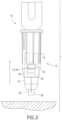
- a third position as illustrated in Figure 3
- the sleeve 14 when the safety pen needle 12 is in a safe mode after use, the sleeve 14 partially encloses and surrounds the needle cannula 20 and hub 30.
- the hub 30 fully encloses the needle cannula 20 in this third position.
- the needle cannula 20 In a first position, as illustrated in Figure 1 , when the safety pen needle 12 is ready for operation, the sleeve 14 encloses and surrounds the needle cannula 20 and hub 30. The hub 30 partially encloses the needle cannula 20 in this third position.
- a second position as illustrated in Figure 2
- the safety pen needle 12 is a single needle cannula 20 device that advantageously hides the needle cannula 20 when not in use (the first and third positions). In other words, the needle cannula 20 is only exposed in the second position during medication delivery.
- the safety pen needle 12 having the single needle cannula 20 is also different from a typical pen needle magazine where a plurality of pen needles is provided for use by the medication delivery pen 10.
- the sleeve 14 is multicolored and cooperates with a shield 16 to visually indicate the status of the safety pen needle 12 in the first, second and third positions.
- the hub 30 and shield 16 can also cooperate together to display the status of the safety pen needle 12 in a similar manner.
- the sleeve 14 cooperates with a window 18 in the shield 16 as described below to depict the status of the safety pen needle 12.
- the window 18 may comprise an opening (cut-out) in the shield 16 with or without a transparent cover.
- the sleeve 14 is partially surrounded by the shield 16 in the first and third positions.
- the shield 16 is movably connected to the hub 30, the needle cannula 20 and the sleeve 14.
- the shield 16 is also pressurized by a spring (see Figure 6 ) to urge the movement of the shield 16.
- the shield 16 in the first position as illustrated in Figure 1 , the shield 16 is in a ready or retracted position and the spring urges the shield 16 toward the retracted position. However, the shield 16 is in an unlocked state and is free to move. The spring does not prevent the shield 16 from moving. Rather, the health care professional can overcome the spring force to move the shield 16. The shield 16 also partially surrounds the sleeve 14.
- the health care professional operates the device by pushing down on the medication delivery pen 10 which is connected to the safety pen needle 12. This pressure causes the needle cannula 20 to deploy into the skin of the patient for medication delivery.
- the shield 16 is extended and moves to a second position to overcome the pressurized force by the compressed spring. The movement of the shield 16 causes the hub 30 and the needle cannula 20 to move from a retracted position (first position) to an extended position (second position).
- the shield 16 fully surrounds the sleeve 14, and the needle cannula 20 extends beyond the shield 16 and sleeve 14 in the second position.
- the health care professional removes the medication delivery pen 10 that is connected to the safety pen needle 12 from the patient.
- the spring urges the shield 16 to move back to the third position.
- the sleeve 14 also moves back to expose the hub 30 and the needle cannula 20.
- the needle cannula 20 is fully enclosed in the hub 30 in the third position.
- the spring advantageously provides automatic retraction of the shield 16 and the needle cannula 20 after use in the second position as the safety pen needle 12 moves to the third position. Similar to the first position, the shield 16 partially surrounds the sleeve 14.
- a locking mechanism (see Figure 7 ) of the safety pen needle 12 locks the shield 16 and prevents the safety pen needle 12 from further use.
- the needle cannula 20 is fully enclosed by the hub 30 and is unable to be exposed in the second position or return for use in the first position.
- the locking mechanism may include, for example, a tab on an inner surface of the shield 16 and a slot on an outer surface of the hub 30, although various other configurations are contemplated herein.
- the first position and the third position are different from each other. Specifically, in the third position, the shield 16 and sleeve 14 are in a further retracted position when compared to the first position. According to another embodiment, the first position and the third position are the same position. In this alternate embodiment, the locking mechanism is configured to be used in the third position but not the first position. In another embodiment, the sleeve 14 is rotated to angularly displace the third position from the first and second position.
- the shield 16 includes the window 18 which visibly indicates needle cannula exposure and safety activation. Specifically, as illustrated in Figure 1 , the window 18 visually exposes a white portion 36 of the sleeve 14 to represent the ready position. In this first position, the safety pen needle 12 is ready for operation and is in an unlocked state to allow various components to move.
- the window 18 visually exposes a green portion 32 of the sleeve 14 to represent the fully deployed position.
- the needle cannula 20 of the safety pen needle 12 is exposed, inserted into the patient and is dispensing medication.
- This visual indication advantageously provides the health care professional confirmation that the needle cannula is in the skin of the patient.
- This visual indication is a significant improvement over a mere tactile notification or needle cannula sensation that the health care professional may previously have relied upon to confirm needle cannula insertion.
- Another advantage this visual indication provides is less training for health care professionals and reduced risk of injection errors.
- the window 18 visually exposes a red portion 34 of the sleeve 14 to represent the safe mode in the third position.
- the needle cannula 20 is retracted into the hub 30 and is locked from further exposure and use.
- This visual indication advantageously provides the health care professional notice that the safety pen needle 12 is in safe activation mode. Such an indication protects patients and health care professionals from being contaminated by used needle cannulas.
- indicia such as numbers, patterns (such as stripes or spots), textures and/or symbols can replace or supplement the green, red or white portions 32, 34, 36 of the sleeve 14 as described above.
- Different patterns or textures can advantageously aid those who are blind, color blind or in cases where red/green colors, for example, are perceived differently in other countries.
- the window 18 can be tinted to adjust what is visually displayed.
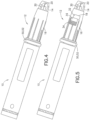
- FIG 4 illustrates a second embodiment of the safety pen needle 12 described above having a smart ring 50 but without a window.
- the smart ring 50 is a circular ring disposed at a proximal end of the safety pen needle 12.
- the smart ring 50 is disposed between the safety pen needle 12 and the medication delivery pen 10.
- the smart ring 50 includes electronics such as electrical contacts or sensors 52 that cooperate with the remaining components of the safety pen needle 12 to sense positional and/or spatial arrangements to determine a position of the shield 16 and dose data.
- the smart ring 50 is able to determine needle insertion and needle exposure time, needle insertion rate and needle exposure rate, the number of injections performed, time intervals between injections and the number of needles used or available for injection.
- the smart ring 50 also determines the position of the shield 16 to identify which of the three positions the safety pen needle 12 is operating in as described above.
- the smart ring 50 communicates positional data or dose data to an external smart device for monitoring and status notification such as if the safety pen needle 12 is in the first, second or third positions.
- the external smart device can be, for example, a mobile phone, laptop, iPad, a smart medication delivery pen or other processing device.
- the smart ring 50 communicates data wirelessly or via a wireline connection to the external smart device.
- Different wireless connectivity methods can be used (e.g., Bluetooth TM or Wi-Fi or near field communication (NFC) technology) which can, in turn, impact device pairing if needed and the need for proximity of the external smart device.
- Bluetooth TM employs a particular device pairing process. The proximity of the two communicating platforms relative to each other depends on the connectivity method used.
- FIG. 5 illustrates a third embodiment of the safety pen needle 12 described above having a smart ring 50 and the window 18.
- This embodiment incorporates the smart ring 50 technology described in the second embodiment, as well as the visual indication feature of the window 18 described in the first embodiment.
- This configuration advantageously provides data communication and status indication through the window 18 at the same time.
- the sleeve 14 is rotated during operation to angularly displace the second position from the first and third position. Accordingly, the sleeve 14 rotates and axially moves from the first position (white portion 36) to the second position (green portion 32) and displays the status through the window 18. After use, the sleeve 14 rotates and axially moves from the second position (green portion 32) to the third position (red portion 34).
- the use of the smart ring 50 in the safety pen needle 12 of the second and third embodiments can prohibit injection until the needle cannula has been fully exposed or fully extended. Such a feature can further mitigate the risk of a failed injection.
- Figure 6 illustrates a fourth embodiment of the safety pen needle 110 that functions in a similar manner as the embodiments described above.
- the safety pen needle 110 includes an outer shield 148 with three colored dots 132, 134, 136 that cooperate with a sleeve 146 having a window 118.
- the safety pen needle 110 further includes an inner shield 116 and a needle 114 fixed to a needle hub 126 that cooperates with a spring 144 to allow for needle 114 movement between an extended and a retracted position.
- the outer shield 148 slides in and out and rotates, depending on the state of the safety pen needle 110.
- Three dots, white 136, red 134, and green 132 are located on the outer shield 148 such that one of the three dots 132, 134, 136 aligns with the window 118 in the sleeve 146, depending on the state of the safety pen needle 110.
- the white dot 136 is visible in the window 118.
- the outer shield 148 will retract into the sleeve 146 and rotate, bringing the green dot 132 into view in the window 118.
- the shield 148 will move forward, bringing the red dot 134 into view through the window 118.
- the spring 144 provides a spring force to return the outer shield 148 of the safety pen needle 110 into the retracted position.
- indicia such as numbers, patterns (such as stripes or spots), textures and/or symbols can replace or supplement the green, red or white colored dots 132, 134, 136 of the outer shield 148 as described above.
- Different patterns or textures can advantageously aid those who are blind, color blind or in cases where red/green colors, for example, are perceived differently in other countries.
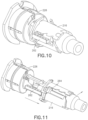
- Figures 7-13 illustrate a fifth embodiment of the safety pen needle having a locking mechanism comprising locking rails 262 and slots 264 as described below.
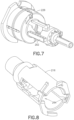
- Figure 7 illustrates a needle hub 226 having the locking rails 262.
- the locking rails 262 are an extruded rectangular member along a longitudinal surface of the needle hub 226.
- the locking rails 262 are disposed on an outer surface of the needle hub 226 in a substantially central axial position.
- Two locking rails 262 are disclosed to be equidistant along the outer surface of the needle hub 226, although more or fewer locking rails are contemplated.
- FIG. 8 illustrates an inner shield 216 having the slots 264.
- the slots 264 are internal rectangular cavities disposed at a proximal end surface of the inner shield 216. As the slots 264 extend beyond the proximal end surface at the proximal end of the inner shield 216, the slots 264 are open and exposed along a length of the inner shield 216.
- the slots 264 are sized to engage the locking rails 262 of the needle hub 226. More or fewer slots 264 are contemplated based on the number of corresponding locking rails 262 in the needle hub 226.
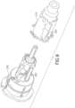
- Figure 9 illustrates the slots 264 of the inner shield 216 being aligned to the locking rails 262 of the needle hub 226 prior to assembly. Subsequently, as illustrated in Figure 10 , the inner shield 216 slides over the needle hub 226 to engage the locking rails 262 in the slots 264. In this position, the locking rails 262 are aligned to openings of the slots 264. Thus, the safety pen needle is in a retracted, unlocked position. The locking rails 262 are exposed because the slots 264 do not enclose the locking rails 262 along a majority of the length of the slot 264.
- Figure 11 illustrates an extended position of the safety pen needle. Specifically, the inner shield 216 moves forward via a spring force from a spring (not illustrated).
- the spring is preferably a torsion spring, although other springs are contemplated.
- Figure 12 illustrates the slots 264 of the inner shield 216 disengaged from the rails 262 of the needle hub 226.
- torsion from the spring causes the inner shield 216 to rotate relative to the needle hub 226.
- the rails 262 are misaligned to the slots 264 and the inner shield 216 can no longer slide back over the needle hub 226. That is, the inner shield 216 is not able to return to the retracted, unlocked position. In this manner, the safety pen needle is in an extended, locked position preventing engagement of the inner shield 216 and the needle hub 226.
- the terms “front,” “rear,” “upper,” “lower,” “upwardly,” “downwardly,” and other orientational descriptors are intended to facilitate the description of the exemplary embodiments of the present invention, and are not intended to limit the structure of the exemplary embodiments of the present invention to any particular position or orientation.
- Terms of degree, such as “substantially” or “approximately” are understood by those of ordinary skill to refer to reasonable ranges outside of the given value, for example, general tolerances associated with manufacturing, assembly, and use of the described embodiments.
Landscapes
- Health & Medical Sciences (AREA)
- Engineering & Computer Science (AREA)
- Heart & Thoracic Surgery (AREA)
- Vascular Medicine (AREA)
- Anesthesiology (AREA)
- Biomedical Technology (AREA)
- Hematology (AREA)
- Life Sciences & Earth Sciences (AREA)
- Animal Behavior & Ethology (AREA)
- General Health & Medical Sciences (AREA)
- Public Health (AREA)
- Veterinary Medicine (AREA)
- Environmental & Geological Engineering (AREA)
- Infusion, Injection, And Reservoir Apparatuses (AREA)
Claims (16)
- Sicherheitsstiftnadelanordnung (12, 110) mit:einem Ansatz (30, 126);einer mit dem Ansatz zusammenwirkenden Nadelkanüle (20, 114), wobei die Nadelkanüle ein distales Ende zum Einführen in einen Patienten und ein sich in den Ansatz erstreckendes proximales Ende aufweist;einer den Ansatz und die Nadelkanüle umgebende Hülse (14, 146);einem Schutz (16) mit einem Fenster (18, 118), wobei der Schutz die Hülse umgibt und in Bezug auf die Hülse von einer ersten Position, in welcher die Hülse die Nadelkanüle und den Ansatz umgibt, zu einer zweiten Position bewegbar ist, in welcher sich die Nadelkanüle über den Ansatz und die Hülse hinaus erstreckt;einem Verriegelungsmechanismus (260), welcher den Schutz mit dem Ansatz in Eingriff bringt, um einen weiteren Gebrauch der Nadelkanüle zu verhindern; undeiner den Schutz drückenden Feder (144),dadurch gekennzeichnet, dass die Sicherheitsstiftnadelanordnung (12, 110), bei welcher ferner:der Schutz (16) in Bezug auf die Hülse zu einer dritten Position bewegbar ist, in welcher das distale Ende der Nadelkanüle teilweise von der Hülse umgeben ist und der Ansatz die Nadelkanüle umschließt;die Feder (144) den Schutz drückt, so dass sich dieser in Bezug auf die Hülse von der ersten Position, in welcher die Feder zusammengedrückt ist, zu der dritten Position bewegt; undein Smart-Ring (50) vorgesehen ist, welcher elektrische Kontakte oder Sensoren aufweist, welche zwei oder mehr der folgenden Parameter ermitteln: eine Position des Schutzes, eine Nadeleinführungs- und Nadelexpositionszeit, eine Nadeleinführrate und eine Nadelexpositionsrate, eine Anzahl der durchgeführten Injektionen, Zeitintervalle zwischen Injektionen, oder die Anzahl von verwendeten oder für Injektionen verfügbaren Nadeln; wobeidas Fenster die Nadelkanülenexposition über eine Markierung an dem Ansatz und eine Sicherheitsaktivierung über den Verriegelungsmechanismus anzeigt.
- Sicherheitsstiftnadelanordnung nach Anspruch 1, bei welcher die Hülse oder der Ansatz in der ersten Position durch das Fenster weiß ist.
- Sicherheitsstiftnadelanordnung nach Anspruch 1, bei welcher die Hülse oder der Ansatz in der zweiten Position durch das Fenster grün ist.
- Sicherheitsstiftnadelanordnung nach Anspruch 1, bei welcher die Hülse oder der Ansatz in der dritten Position durch das Fenster rot ist.
- Sicherheitsstiftnadelanordnung nach Anspruch 1, bei welcher die Hülse oder der Ansatz Zahlen, Muster, Texturen und/oder Symbole durch das Fenster anzeigt, um die erste, die zweite und die dritte Position anzuzeigen.
- Sicherheitsstiftnadelanordnung nach Anspruch 1, bei welcher die erste Position eine entriegelte Position ist, in welcher der Schutz frei ist, sich zum Freilegen oder Abdecken der Nadelkanüle zu bewegen.
- Sicherheitsstiftnadelanordnung nach Anspruch 1, bei welcher die dritte Position eine verriegelte Position ist, in welcher der Schutz arretiert ist, um die Nadelkanüle fest abzudecken.
- Sicherheitsstiftnadelanordnung nach Anspruch 1, bei welcher die Nadelkanüle durch den Ansatz in der ersten und der dritten Position zurückgezogen und abgedeckt ist.
- Sicherheitsstiftnadelanordnung nach Anspruch 1, bei welcher der Smart-Ring mit einem intelligenten Gerät kommuniziert.
- Sicherheitsstiftnadelanordnung nach Anspruch 9, bei welcher der Smart-Ring einen Bereitschafts-, einen vollständig ausgefahrenen oder einen sicheren Modus kommuniziert.
- Sicherheitsstiftnadelanordnung nach Anspruch 1, bei welcher der Smart-Ring an einem proximalen Ende der Sicherheitsstiftnadelanordnung angeordnet ist.
- Medikamentenausgabe-Sicherheitsstiftnadelanordnung (12, 110) mit:einem Medikamentenausgabestift (10); undder Sicherheitsstiftnadelanordnung nach Anspruch 1, wobeider Smart-Ring an einem distalen Ende des Medikamentenausgabestifts und an einem proximalen Ende der Sicherheitsstiftnadelanordnung angeordnet ist.
- Sicherheitsstiftnadelanordnung nach Anspruch 1, bei welcher der Schutz Schlitze (264) aufweist, die in einer zurückgezogenen, entriegelten Position mit Leisten (262) an dem Ansatz zusammengreifen.
- Sicherheitsstiftnadelanordnung nach Anspruch 13, bei welcher die Schlitze in einer ausgefahrenen, verriegelten Position auf die Leisten ausgerichtet sind.
- Sicherheitsstiftnadelanordnung nach Anspruch 13, ferner mit einer Feder, welche den Schutz in Bezug auf den Ansatz dreht, um die Schlitze in Bezug auf die Leisten zu versetzen.
- Sicherheitsstiftnadelanordnung nach Anspruch 1, bei welcher das Fenster einen ersten Bereich (36) der Hülse visuell freilegt, um eine Bereitschaftsposition oder die erste Position wiederzugeben, das Fenster einen zweiten Bereich (32) der Hülse visuell freilegt, um eine voll ausgefahrene Position oder die zweite Position wiederzugeben, und das Fenster einen dritten Bereich (34) der Hülse visuell freilegt, um einen sicheren Modus oder die dritte Position wiederzugeben, in welcher die Nadelkanüle gegen weiteres Freiliegen und weiteren Gebrauch verriegelt ist.
Applications Claiming Priority (2)
| Application Number | Priority Date | Filing Date | Title |
|---|---|---|---|
| US201762483629P | 2017-04-10 | 2017-04-10 | |
| PCT/US2018/026078 WO2018191076A1 (en) | 2017-04-10 | 2018-04-04 | Safety pen needle variable indicator |
Publications (3)
| Publication Number | Publication Date |
|---|---|
| EP3609558A1 EP3609558A1 (de) | 2020-02-19 |
| EP3609558A4 EP3609558A4 (de) | 2020-12-16 |
| EP3609558B1 true EP3609558B1 (de) | 2025-06-11 |
Family
ID=63793731
Family Applications (1)
| Application Number | Title | Priority Date | Filing Date |
|---|---|---|---|
| EP18784982.3A Active EP3609558B1 (de) | 2017-04-10 | 2018-04-04 | Variabler indikator für nadel eines sicherheitspens |
Country Status (6)
| Country | Link |
|---|---|
| US (1) | US11364350B2 (de) |
| EP (1) | EP3609558B1 (de) |
| JP (1) | JP7370315B2 (de) |
| CN (2) | CN114949457A (de) |
| CA (1) | CA3055788A1 (de) |
| WO (1) | WO2018191076A1 (de) |
Families Citing this family (4)
| Publication number | Priority date | Publication date | Assignee | Title |
|---|---|---|---|---|
| JP7378436B2 (ja) * | 2018-06-25 | 2023-11-13 | サノフイ | 薬剤送達デバイス |
| WO2022098592A1 (en) * | 2020-11-04 | 2022-05-12 | Amgen Inc. | Drug delivery device assembly and accessory for drug delivery device |
| JP7525955B2 (ja) | 2021-04-08 | 2024-07-31 | ラブ ライフサイエンシズ エルエルシー | プレフィルドシリンジ安全デバイスおよび注射器 |
| WO2025114264A1 (en) | 2023-11-28 | 2025-06-05 | Novo Nordisk A/S | Shielded needle unit with lock indicator |
Family Cites Families (24)
| Publication number | Priority date | Publication date | Assignee | Title |
|---|---|---|---|---|
| US6547764B2 (en) * | 2000-05-31 | 2003-04-15 | Novo Nordisk A/S | Double pointed injection needle |
| EP1289587B1 (de) | 2000-05-31 | 2005-08-03 | Novo Nordisk A/S | Wegwerfbare doppelspritzeninjektionsnadel |
| WO2002009797A1 (en) | 2000-08-02 | 2002-02-07 | Becton Dickinson And Company | Pen needle and safety shield system |
| ES2257597T3 (es) * | 2001-11-30 | 2006-08-01 | Novo Nordisk A/S | Ensamblaje de aguja de seguridad. |
| US20090280065A1 (en) * | 2006-04-10 | 2009-11-12 | Willian Mary K | Uses and Compositions for Treatment of Psoriasis |
| US6805686B1 (en) | 2003-05-06 | 2004-10-19 | Abbott Laboratories | Autoinjector with extendable needle protector shroud |
| US7497847B2 (en) * | 2003-11-03 | 2009-03-03 | Becton, Dickinson And Company | Safety shield system for a syringe |
| CA2719110C (en) | 2008-03-13 | 2017-07-25 | Becton, Dickinson And Company | Safety needle assembly |
| GB2463034B (en) * | 2008-08-28 | 2012-11-07 | Owen Mumford Ltd | Autoinjection devices |
| US8876781B2 (en) * | 2009-06-18 | 2014-11-04 | Shl Group Ab | Safety pen needle device |
| CN102905747B (zh) * | 2010-03-25 | 2014-10-29 | 赛诺菲-安万特德国有限公司 | 针组件 |
| AU2011231688B2 (en) * | 2010-03-25 | 2014-12-04 | Sanofi-Aventis Deutschland Gmbh | Medicated module with user selection |
| CA2818833A1 (en) * | 2010-11-29 | 2012-06-07 | Thomas Urs Thueer | Medicated module with automatic reservoir engagement |
| EP2514450A1 (de) | 2011-04-21 | 2012-10-24 | Sanofi-Aventis Deutschland GmbH | Medizinisches Modul mit automatischer Reservoiraufnahme und magnetischem Sperrmechanismus |
| CA2832957A1 (en) * | 2011-04-21 | 2012-10-26 | Sanofi-Aventis Deutschland Gmbh | Medicated module with automatic reservoir engagement and lock mechanism |
| EP2699292A1 (de) | 2011-04-21 | 2014-02-26 | Sanofi-Aventis Deutschland GmbH | Medizinisches modul mit automatischem betätigungsmechanismus |
| US8496619B2 (en) * | 2011-07-15 | 2013-07-30 | Antares Pharma, Inc. | Injection device with cammed ram assembly |
| EP2578257A1 (de) * | 2011-10-06 | 2013-04-10 | Sanofi-Aventis Deutschland GmbH | Nadelsicherheitsvorrichtung |
| EP2789357B1 (de) * | 2011-12-09 | 2017-04-26 | Panasonic Healthcare Holdings Co., Ltd. | Pharmazeutische spritzeneinheit und pharmazeutische injektionsvorrichtung |
| EP2716318A1 (de) * | 2012-10-04 | 2014-04-09 | Sanofi-Aventis Deutschland GmbH | Medikamentenausgabevorrichtung mit Medikamentenabgabestartanzeige |
| ES2806983T3 (es) | 2015-04-10 | 2021-02-19 | Novo Nordisk As | Dispositivo médico de inyección que tiene un protector |
| GB201507981D0 (en) * | 2015-05-11 | 2015-06-24 | Owen Mumford Ltd | Needle assemblies |
| JP2018515232A (ja) | 2015-05-12 | 2018-06-14 | ノボ・ノルデイスク・エー/エス | 薬剤送達装置のための回転センサ構造体 |
| EP3380159B1 (de) * | 2015-11-27 | 2019-10-23 | Sanofi-Aventis Deutschland GmbH | Einspritzvorrichtung |
-
2018
- 2018-04-04 WO PCT/US2018/026078 patent/WO2018191076A1/en not_active Ceased
- 2018-04-04 CN CN202210733149.5A patent/CN114949457A/zh active Pending
- 2018-04-04 JP JP2020504097A patent/JP7370315B2/ja active Active
- 2018-04-04 CN CN201880024153.6A patent/CN110494179B/zh active Active
- 2018-04-04 US US16/603,990 patent/US11364350B2/en active Active
- 2018-04-04 EP EP18784982.3A patent/EP3609558B1/de active Active
- 2018-04-04 CA CA3055788A patent/CA3055788A1/en active Pending
Also Published As
| Publication number | Publication date |
|---|---|
| WO2018191076A1 (en) | 2018-10-18 |
| US11364350B2 (en) | 2022-06-21 |
| US20200114090A1 (en) | 2020-04-16 |
| EP3609558A1 (de) | 2020-02-19 |
| JP7370315B2 (ja) | 2023-10-27 |
| CN114949457A (zh) | 2022-08-30 |
| EP3609558A4 (de) | 2020-12-16 |
| CN110494179B (zh) | 2022-07-22 |
| CN110494179A (zh) | 2019-11-22 |
| JP2020516420A (ja) | 2020-06-11 |
| CA3055788A1 (en) | 2018-10-18 |
Similar Documents
| Publication | Publication Date | Title |
|---|---|---|
| CN102905747B (zh) | 针组件 | |
| EP1605992B1 (de) | Halterung mit schutzschild für eine wirkstofffreisetzungsvorrichtung | |
| EP2231235B1 (de) | Stiftnadelbaugruppe mit nadeleinsatzmechanismus | |
| CN105592876B (zh) | 安全针设备 | |
| US11364350B2 (en) | Safety pen needle variable indicator | |
| ES2247343T3 (es) | Sistema de proteccion de seguridad para jeringuillas precargadas. | |
| JP2005530597A (ja) | 医療用注射針アセンブリ | |
| CN110958895A (zh) | 一种安全型注射装置、注射器及其组装方法 | |
| CN104321099A (zh) | 具有用于防止不经意驱动的安全特征的输注装置 | |
| KR20140027466A (ko) | 주입 장치 | |
| EP3047866B1 (de) | Autoinjektor mit visueller dosisendanzeige | |
| MX2012004446A (es) | Dispositivo de suministro de farmacos activado con la palma de la mano. | |
| MX2012015039A (es) | Dispositivo de seguridad para una jeringa precargada y dispositivo de inyeccion. | |
| US20100160869A1 (en) | Medical Needle Assemblies | |
| EP3534987B1 (de) | System zur verabreichung eines arzneimittels mit einstellbarer dosis | |
| CA2671759A1 (en) | Shieldable needle assembly with biased safety shield | |
| EP3749398B1 (de) | Sicherheitsnadelvorrichtung | |
| WO2021211412A1 (en) | Injection device with passive safety mechanism | |
| CN214129793U (zh) | 用于药物输送装置的针头护罩 | |
| EP4129367B1 (de) | Kappenanordnung für eine nadel | |
| WO2025160425A1 (en) | Pre-filled syringe safety devices and injectors, systems, and methods of use | |
| WO2008132518A1 (en) | Piercing needle assembly irreversibly locked with a reversible latching mechanism | |
| HK1234356A1 (en) | Medicine delivery device with restricted access filling port |
Legal Events
| Date | Code | Title | Description |
|---|---|---|---|
| STAA | Information on the status of an ep patent application or granted ep patent |
Free format text: STATUS: THE INTERNATIONAL PUBLICATION HAS BEEN MADE |
|
| PUAI | Public reference made under article 153(3) epc to a published international application that has entered the european phase |
Free format text: ORIGINAL CODE: 0009012 |
|
| STAA | Information on the status of an ep patent application or granted ep patent |
Free format text: STATUS: REQUEST FOR EXAMINATION WAS MADE |
|
| 17P | Request for examination filed |
Effective date: 20191002 |
|
| AK | Designated contracting states |
Kind code of ref document: A1 Designated state(s): AL AT BE BG CH CY CZ DE DK EE ES FI FR GB GR HR HU IE IS IT LI LT LU LV MC MK MT NL NO PL PT RO RS SE SI SK SM TR |
|
| AX | Request for extension of the european patent |
Extension state: BA ME |
|
| RIN1 | Information on inventor provided before grant (corrected) |
Inventor name: MANOCCHIO, JOHN Inventor name: OZA, KUNJAL Inventor name: VIEIRA, LOUIS Inventor name: BOWEN, MARK |
|
| DAV | Request for validation of the european patent (deleted) | ||
| DAX | Request for extension of the european patent (deleted) | ||
| A4 | Supplementary search report drawn up and despatched |
Effective date: 20201113 |
|
| RIC1 | Information provided on ipc code assigned before grant |
Ipc: A61M 5/20 20060101AFI20201109BHEP Ipc: A61M 5/32 20060101ALI20201109BHEP Ipc: A61M 5/24 20060101ALI20201109BHEP |
|
| STAA | Information on the status of an ep patent application or granted ep patent |
Free format text: STATUS: EXAMINATION IS IN PROGRESS |
|
| 17Q | First examination report despatched |
Effective date: 20210730 |
|
| RAP1 | Party data changed (applicant data changed or rights of an application transferred) |
Owner name: EMBECTA CORP. |
|
| GRAP | Despatch of communication of intention to grant a patent |
Free format text: ORIGINAL CODE: EPIDOSNIGR1 |
|
| STAA | Information on the status of an ep patent application or granted ep patent |
Free format text: STATUS: GRANT OF PATENT IS INTENDED |
|
| INTG | Intention to grant announced |
Effective date: 20250102 |
|
| GRAS | Grant fee paid |
Free format text: ORIGINAL CODE: EPIDOSNIGR3 |
|
| GRAA | (expected) grant |
Free format text: ORIGINAL CODE: 0009210 |
|
| STAA | Information on the status of an ep patent application or granted ep patent |
Free format text: STATUS: THE PATENT HAS BEEN GRANTED |
|
| AK | Designated contracting states |
Kind code of ref document: B1 Designated state(s): AL AT BE BG CH CY CZ DE DK EE ES FI FR GB GR HR HU IE IS IT LI LT LU LV MC MK MT NL NO PL PT RO RS SE SI SK SM TR |
|
| REG | Reference to a national code |
Ref country code: GB Ref legal event code: FG4D |
|
| REG | Reference to a national code |
Ref country code: CH Ref legal event code: EP |
|
| REG | Reference to a national code |
Ref country code: IE Ref legal event code: FG4D |
|
| REG | Reference to a national code |
Ref country code: DE Ref legal event code: R096 Ref document number: 602018082548 Country of ref document: DE |
|
| PG25 | Lapsed in a contracting state [announced via postgrant information from national office to epo] |
Ref country code: FI Free format text: LAPSE BECAUSE OF FAILURE TO SUBMIT A TRANSLATION OF THE DESCRIPTION OR TO PAY THE FEE WITHIN THE PRESCRIBED TIME-LIMIT Effective date: 20250611 Ref country code: ES Free format text: LAPSE BECAUSE OF FAILURE TO SUBMIT A TRANSLATION OF THE DESCRIPTION OR TO PAY THE FEE WITHIN THE PRESCRIBED TIME-LIMIT Effective date: 20250611 |
|
| REG | Reference to a national code |
Ref country code: LT Ref legal event code: MG9D |
|
| PG25 | Lapsed in a contracting state [announced via postgrant information from national office to epo] |
Ref country code: NO Free format text: LAPSE BECAUSE OF FAILURE TO SUBMIT A TRANSLATION OF THE DESCRIPTION OR TO PAY THE FEE WITHIN THE PRESCRIBED TIME-LIMIT Effective date: 20250911 Ref country code: GR Free format text: LAPSE BECAUSE OF FAILURE TO SUBMIT A TRANSLATION OF THE DESCRIPTION OR TO PAY THE FEE WITHIN THE PRESCRIBED TIME-LIMIT Effective date: 20250912 |
|
| REG | Reference to a national code |
Ref country code: NL Ref legal event code: MP Effective date: 20250611 |
|
| PG25 | Lapsed in a contracting state [announced via postgrant information from national office to epo] |
Ref country code: BG Free format text: LAPSE BECAUSE OF FAILURE TO SUBMIT A TRANSLATION OF THE DESCRIPTION OR TO PAY THE FEE WITHIN THE PRESCRIBED TIME-LIMIT Effective date: 20250611 |
|
| PG25 | Lapsed in a contracting state [announced via postgrant information from national office to epo] |
Ref country code: HR Free format text: LAPSE BECAUSE OF FAILURE TO SUBMIT A TRANSLATION OF THE DESCRIPTION OR TO PAY THE FEE WITHIN THE PRESCRIBED TIME-LIMIT Effective date: 20250611 |
|
| PG25 | Lapsed in a contracting state [announced via postgrant information from national office to epo] |
Ref country code: RS Free format text: LAPSE BECAUSE OF FAILURE TO SUBMIT A TRANSLATION OF THE DESCRIPTION OR TO PAY THE FEE WITHIN THE PRESCRIBED TIME-LIMIT Effective date: 20250911 |
|
| PG25 | Lapsed in a contracting state [announced via postgrant information from national office to epo] |
Ref country code: LV Free format text: LAPSE BECAUSE OF FAILURE TO SUBMIT A TRANSLATION OF THE DESCRIPTION OR TO PAY THE FEE WITHIN THE PRESCRIBED TIME-LIMIT Effective date: 20250611 |
|
| PG25 | Lapsed in a contracting state [announced via postgrant information from national office to epo] |
Ref country code: NL Free format text: LAPSE BECAUSE OF FAILURE TO SUBMIT A TRANSLATION OF THE DESCRIPTION OR TO PAY THE FEE WITHIN THE PRESCRIBED TIME-LIMIT Effective date: 20250611 |
|
| PG25 | Lapsed in a contracting state [announced via postgrant information from national office to epo] |
Ref country code: PT Free format text: LAPSE BECAUSE OF FAILURE TO SUBMIT A TRANSLATION OF THE DESCRIPTION OR TO PAY THE FEE WITHIN THE PRESCRIBED TIME-LIMIT Effective date: 20251013 |
|
| REG | Reference to a national code |
Ref country code: AT Ref legal event code: MK05 Ref document number: 1801872 Country of ref document: AT Kind code of ref document: T Effective date: 20250611 |
|
| PG25 | Lapsed in a contracting state [announced via postgrant information from national office to epo] |
Ref country code: IS Free format text: LAPSE BECAUSE OF FAILURE TO SUBMIT A TRANSLATION OF THE DESCRIPTION OR TO PAY THE FEE WITHIN THE PRESCRIBED TIME-LIMIT Effective date: 20251011 |
|
| PG25 | Lapsed in a contracting state [announced via postgrant information from national office to epo] |
Ref country code: AT Free format text: LAPSE BECAUSE OF FAILURE TO SUBMIT A TRANSLATION OF THE DESCRIPTION OR TO PAY THE FEE WITHIN THE PRESCRIBED TIME-LIMIT Effective date: 20250611 Ref country code: SM Free format text: LAPSE BECAUSE OF FAILURE TO SUBMIT A TRANSLATION OF THE DESCRIPTION OR TO PAY THE FEE WITHIN THE PRESCRIBED TIME-LIMIT Effective date: 20250611 |
|
| PG25 | Lapsed in a contracting state [announced via postgrant information from national office to epo] |
Ref country code: CZ Free format text: LAPSE BECAUSE OF FAILURE TO SUBMIT A TRANSLATION OF THE DESCRIPTION OR TO PAY THE FEE WITHIN THE PRESCRIBED TIME-LIMIT Effective date: 20250611 |
|
| PG25 | Lapsed in a contracting state [announced via postgrant information from national office to epo] |
Ref country code: PL Free format text: LAPSE BECAUSE OF FAILURE TO SUBMIT A TRANSLATION OF THE DESCRIPTION OR TO PAY THE FEE WITHIN THE PRESCRIBED TIME-LIMIT Effective date: 20250611 |
|
| PG25 | Lapsed in a contracting state [announced via postgrant information from national office to epo] |
Ref country code: EE Free format text: LAPSE BECAUSE OF FAILURE TO SUBMIT A TRANSLATION OF THE DESCRIPTION OR TO PAY THE FEE WITHIN THE PRESCRIBED TIME-LIMIT Effective date: 20250611 |
|
| PG25 | Lapsed in a contracting state [announced via postgrant information from national office to epo] |
Ref country code: RO Free format text: LAPSE BECAUSE OF FAILURE TO SUBMIT A TRANSLATION OF THE DESCRIPTION OR TO PAY THE FEE WITHIN THE PRESCRIBED TIME-LIMIT Effective date: 20250611 Ref country code: SK Free format text: LAPSE BECAUSE OF FAILURE TO SUBMIT A TRANSLATION OF THE DESCRIPTION OR TO PAY THE FEE WITHIN THE PRESCRIBED TIME-LIMIT Effective date: 20250611 |
|
| REG | Reference to a national code |
Ref country code: DE Ref legal event code: R097 Ref document number: 602018082548 Country of ref document: DE |
|
| PG25 | Lapsed in a contracting state [announced via postgrant information from national office to epo] |
Ref country code: DK Free format text: LAPSE BECAUSE OF FAILURE TO SUBMIT A TRANSLATION OF THE DESCRIPTION OR TO PAY THE FEE WITHIN THE PRESCRIBED TIME-LIMIT Effective date: 20250611 |
|
| PG25 | Lapsed in a contracting state [announced via postgrant information from national office to epo] |
Ref country code: IT Free format text: LAPSE BECAUSE OF FAILURE TO SUBMIT A TRANSLATION OF THE DESCRIPTION OR TO PAY THE FEE WITHIN THE PRESCRIBED TIME-LIMIT Effective date: 20250611 |
|
| PLBE | No opposition filed within time limit |
Free format text: ORIGINAL CODE: 0009261 |
|
| STAA | Information on the status of an ep patent application or granted ep patent |
Free format text: STATUS: NO OPPOSITION FILED WITHIN TIME LIMIT |
|
| REG | Reference to a national code |
Ref country code: CH Ref legal event code: L10 Free format text: ST27 STATUS EVENT CODE: U-0-0-L10-L00 (AS PROVIDED BY THE NATIONAL OFFICE) Effective date: 20260423 |