EP3609364B1 - System zum aufbringen mindestens zweier arten von flüssigkeit auf jeweilige zielbereiche eines substrats und verfahren dafür - Google Patents
System zum aufbringen mindestens zweier arten von flüssigkeit auf jeweilige zielbereiche eines substrats und verfahren dafür Download PDFInfo
- Publication number
- EP3609364B1 EP3609364B1 EP18712276.7A EP18712276A EP3609364B1 EP 3609364 B1 EP3609364 B1 EP 3609364B1 EP 18712276 A EP18712276 A EP 18712276A EP 3609364 B1 EP3609364 B1 EP 3609364B1
- Authority
- EP
- European Patent Office
- Prior art keywords
- liquid
- substrate
- applicator
- pressured gas
- nozzle
- Prior art date
- Legal status (The legal status is an assumption and is not a legal conclusion. Google has not performed a legal analysis and makes no representation as to the accuracy of the status listed.)
- Active
Links
Images


Classifications
-
- A—HUMAN NECESSITIES
- A45—HAND OR TRAVELLING ARTICLES
- A45D—HAIRDRESSING OR SHAVING EQUIPMENT; EQUIPMENT FOR COSMETICS OR COSMETIC TREATMENTS, e.g. FOR MANICURING OR PEDICURING
- A45D44/00—Other cosmetic or toiletry articles, e.g. for hairdressers' rooms
- A45D44/002—Masks for cosmetic treatment of the face
-
- B—PERFORMING OPERATIONS; TRANSPORTING
- B05—SPRAYING OR ATOMISING IN GENERAL; APPLYING FLUENT MATERIALS TO SURFACES, IN GENERAL
- B05B—SPRAYING APPARATUS; ATOMISING APPARATUS; NOZZLES
- B05B12/00—Arrangements for controlling delivery; Arrangements for controlling the spray area
- B05B12/02—Arrangements for controlling delivery; Arrangements for controlling the spray area for controlling time, or sequence, of delivery
- B05B12/04—Arrangements for controlling delivery; Arrangements for controlling the spray area for controlling time, or sequence, of delivery for sequential operation or multiple outlets
-
- B—PERFORMING OPERATIONS; TRANSPORTING
- B41—PRINTING; LINING MACHINES; TYPEWRITERS; STAMPS
- B41J—TYPEWRITERS; SELECTIVE PRINTING MECHANISMS, i.e. MECHANISMS PRINTING OTHERWISE THAN FROM A FORME; CORRECTION OF TYPOGRAPHICAL ERRORS
- B41J3/00—Typewriters or selective printing or marking mechanisms characterised by the purpose for which they are constructed
- B41J3/407—Typewriters or selective printing or marking mechanisms characterised by the purpose for which they are constructed for marking on special material
-
- A—HUMAN NECESSITIES
- A45—HAND OR TRAVELLING ARTICLES
- A45D—HAIRDRESSING OR SHAVING EQUIPMENT; EQUIPMENT FOR COSMETICS OR COSMETIC TREATMENTS, e.g. FOR MANICURING OR PEDICURING
- A45D2200/00—Details not otherwise provided for in A45D
- A45D2200/05—Details of containers
- A45D2200/054—Means for supplying liquid to the outlet of the container
- A45D2200/057—Spray nozzles; Generating atomised liquid
-
- A—HUMAN NECESSITIES
- A45—HAND OR TRAVELLING ARTICLES
- A45D—HAIRDRESSING OR SHAVING EQUIPMENT; EQUIPMENT FOR COSMETICS OR COSMETIC TREATMENTS, e.g. FOR MANICURING OR PEDICURING
- A45D2200/00—Details not otherwise provided for in A45D
- A45D2200/05—Details of containers
- A45D2200/058—Means for mixing different substances prior to application
-
- A—HUMAN NECESSITIES
- A61—MEDICAL OR VETERINARY SCIENCE; HYGIENE
- A61F—FILTERS IMPLANTABLE INTO BLOOD VESSELS; PROSTHESES; DEVICES PROVIDING PATENCY TO, OR PREVENTING COLLAPSING OF, TUBULAR STRUCTURES OF THE BODY, e.g. STENTS; ORTHOPAEDIC, NURSING OR CONTRACEPTIVE DEVICES; FOMENTATION; TREATMENT OR PROTECTION OF EYES OR EARS; BANDAGES, DRESSINGS OR ABSORBENT PADS; FIRST-AID KITS
- A61F7/00—Heating or cooling appliances for medical or therapeutic treatment of the human body
- A61F2007/0001—Body part
- A61F2007/0002—Head or parts thereof
- A61F2007/0003—Face
-
- A—HUMAN NECESSITIES
- A61—MEDICAL OR VETERINARY SCIENCE; HYGIENE
- A61Q—SPECIFIC USE OF COSMETICS OR SIMILAR TOILETRY PREPARATIONS
- A61Q19/00—Preparations for care of the skin
Definitions
- the present invention relates to a system and a method for applying at least two kinds of liquid, i.e. two fluid cosmetic formulas and one binder, onto respective targeted areas of a substrate to, for example, form a facial mask, etc.
- the present invention further relates to a product produced by such a system and method.
- the skin care required for a user's face varies from region to region of the user, and the care needed for these different regions is different.
- the T-zone of the skin tends to be oilier than the U-zone of the skin, and therefore the skin care compositions needed for these two zones of the face are different from each other.
- Another example is the zone around eyes and the remaining zones of the face, both of which need different skin treatments.
- a substrate-based cosmetic product comprising different cosmetic formulas for targeted zones may be a solution for such a multifunctional product.
- a "substrate-based cosmetic product” refers to a cosmetic product in which a substrate is impregnated with a liquid cosmetic.
- the level of impregnation in such products varies from product to product. In general, in the case of a facial mask, the level of impregnation is 15 grams to 40 grams per mask sheet, while in the case of wipes, it is 3 grams to 6 grams per wipe sheet.
- US2006/0104931A1 proposes a cosmetic treatment article, more specifically a face mask composed of different gel formulas.
- US2006/0104931A1 does not disclose a system which is able to apply different gel formulas on respective targeted areas of the mask.
- the formulas are in gel form, transfer of the formulas to the skin is limited.
- US2010/0191314A1 describes a temperature-controlled facial mask with area-specific treatments, wherein the treatments or formulas are sandwiched between two layers of substrate. These formulas can be applied on targeted zones of the substrates by any depiction technique such as lithography, screen printing, ink jet printing, etc. However, US2010/0191314A1 does not describe how to achieve sufficient quantities of formula deposition on the substrates with these techniques.
- WO2011/146321A2 describes a method and system for automatic or manual evaluation to provide targeted and individualized delivery of cosmetic actives in a mask or patch form.
- WO2011/146321A2 proposes using a heatless printing system so that compositions can be printed on a substrate without decomposition.
- WO2011/146321A2 does not describe how to achieve sufficient quantities of formula printing on the substrate.
- US 2002/024570 discloses an ink-jet printing system including a printing frame constructed for containing four ink containers. Each container contains a different color ink so that four color printing can be accomplished using cyan, yellow, magenta and black inks.
- the frame has a control panel for controlling the operation of the printer and a media slot from which the media (paper) is ejected.
- US 2004/012655 discloses a system for preventing a print head from drawing gas from an ink line when the system is turned off.
- WO 2015/027055 discloses a skin-treatment delivery device for delivering a treatment regimen to the skin surface of a user.
- WO 86/07310 discloses a fluid jet printing device having a source for supplying fluid under pressure to a printer head.
- an object of the present invention is to provide a system as defined in claim 1 and a method as defined in claim 6.
- the present invention provides a product as defined in claim 7.
- At least two kinds of liquid are applied by the action of a pressured gas onto the respective targeted areas of the substrate.
- the liquids can be applied onto the respective targeted areas of the substrate in considerably greater amounts per unit time compared to methods such as lithography, screen printing, ink jet printing, etc.
- substrate-based wet products in which sufficient amounts of at least two kinds of liquid have been applied onto individual targeted areas of a substrate, can be obtained efficiently in a short amount of time. Products obtained thereby may be immediately placed on the surface of the body of a user for the purpose of targeted treatment. Alternatively, such products may be semi dried so as to be packable without any mixing of the different liquids.
- the first applicator includes at least one first valve that corresponds to the nozzle and is operable to be opened/closed so as to permit or block the flow of the first liquid to the nozzle
- the second applicator includes at least one second valve that corresponds to the nozzle and is operable to be opened/closed so as to permit or block the flow of the second liquid to the nozzle
- the controller is configured to be capable of individually controlling an opening/closing operation of the first and second valves.
- the system includes a conveyor for conveying the substrate along a direction parallel to a surface of the substrate, wherein the controller is configured to be capable of simultaneously controlling the spraying operation of the first and second applicator and a conveying operation of the conveyor so that the first and second applicator and the conveyor operate in a coordinated manner.
- the first and second applicator are configured to be capable of reciprocal movement in a direction orthogonal to a conveying direction of the substrate, and the controller is configured to be capable of simultaneously controlling the spraying operation and the reciprocal movement of the first and second applicator and the conveying operation of the conveyor so that the first and second applicator and the conveyor operate in a coordinated manner.
- the system includes a third storage unit for accommodating a third liquid, wherein the pressured gas supply unit is further fluidly connected to the third storage unit; and a third applicator that is fluidly connected to the third storage unit, wherein the third applicator includes at least one nozzle disposed so as to face the substrate, and wherein the third applicator is configured to be capable of spraying the third liquid within the third storage unit from the nozzle toward the substrate by the action of the pressured gas from the pressured gas supply unit, wherein the controller is configured to be capable of individually controlling the spraying operation of the first to third applicator so that the third applicator sprays the third liquid toward a boundary area between the targeted area for the first liquid and the targeted area for the second liquid on the substrate.
- a binder preferably a quick-drying binder, is used as the third liquid, mixing of the first and second liquids in the boundary between the two liquids after application can be reliably prevented.
- the third applicator includes at least one third valve that corresponds to the nozzle and is operable to be opened/closed so as to permit or block the flow of the third liquid to the nozzle, wherein the controller is configured to be capable of individually controlling an opening/closing operation of the first to third valves.
- the pressured gas supply unit is a compressor and/or a pressured gas storage tank. Further, it is particularly preferable to use pressured air as the pressured gas.
- the substrate may be a sheet-like substrate of a cosmetic article, for example a facial mask, facial patch, or facial wipe.
- the application level per unit area of the liquids may be at least 300 grams/m 2 .
- the product may be a cosmetic article such as a facial mask.
- FIGS. 1 to 4 An embodiment of the present invention will now be explained referring to FIGS. 1 to 4 .
- three kinds of liquid i.e. two fluid cosmetic formulas and one binder, are used.
- the present invention may be similarly carried out using three or more kinds of liquid with using a binder.
- the substrate S is a sheet-like substrate of a cosmetic article, particularly a facial mask.
- the substrate S is manufactured from, for example, a nonwoven sheet consisting of cellulose, and more specifically a 100% viscose spun lace nonwoven sheet of 50 gsm (grams/m 2 ).
- the substrate S can be any shape and size, one of examples can be substrate S in the shape of facial mask.
- the two cosmetic formulas (a serum, a lotion, etc.) are applied onto (or impregnated into) the substrate S, and thereby a wet facial mask is obtained.
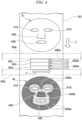
- elliptical openings are formed at positions corresponding to the eyes and mouth of a user of the substrate S serving as the facial mask.
- a U-shaped slit is formed at a position corresponding to the nose of the user (refer to FIG. 4 ).
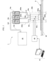
- the system 1 includes first and second storage tanks 10a, 10b that respectively accommodate a first fluid cosmetic formula F 1 and a second fluid cosmetic formula F 2 which are made of different components, and a third storage tank 10c that accommodates a quick-drying binder F 3 .
- the tanks 10a, 10b, and 10c may be in a separated state, or may be integrated as shown in the drawings.
- the tanks 10a, 10b, and 10c also may be installed at positions separated from the application units (i.e., the applicators) to be explained later, or may be integrated with their respective application units.
- the system 1 also includes a pressured gas supply unit 20 that is fluidly connected to the first to third tanks 10a to 10c via a flexible tube 100.
- the unit 20 is configured to be capable of causing the pressure of a pressured gas to act on the first and second fluid cosmetic formulas F 1 and F 2 and the binder F 3 within the tanks 10a to 10c. Therefore, during operation of the system 1, the pressure of the pressured gas acts as shown by the arrows in FIG. 1 on the liquid surfaces of the first and second fluid cosmetic formulas F 1 and F 2 and the binder F 3 .
- the pressured gas supply unit 20 is a compressor. However, alternatively, a pressured gas storage tank may also be used. Further, in the present embodiment, the pressured gas is pressured air. However, alternatively, another gas that is not reactive with the formulas and binder used in the system 1 may also be used.
- the unit 20 includes a sensor that detects the pressure of the pressured gas to be supplied to the first to third tanks 10a to 10c. Information obtained from this sensor may be input into the control unit to be explained later as an operation parameter.
- the system 1 also includes first to third application units 30a, 30b, 30c that are fluidly connected to the first to third storage tanks 10a to 10c via flexible tubes 200a, 200b, 200c.
- the first to third application units 30a to 30c are joined to each other.
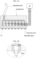
- the first application unit 30a includes a plurality of nozzles 300a that are disposed in one row, particularly one row in a direction orthogonal to the conveying direction of the substrate S, so as to face the substrate S.
- the first application unit 30a is configured to be capable of spraying the first fluid cosmetic formula F 1 within the tank 10a from the nozzles 300a toward the substrate S by the action of the pressured gas from the unit 20.
- the second and third applications units 30b and 30c also have the same structure.
- the second application unit 30b also includes a plurality of nozzles 300b disposed in one row so as to face the substrate S, and can spray the second fluid cosmetic formula F 2 within the tank 10b from the nozzles 300b toward the substrate S by the action of the pressured gas from the unit 20.
- the third application unit 30c also includes a plurality of nozzles 300c disposed in one row so as to face the substrate S, and can spray the binder F 3 within the tank 10c from the nozzles 300c toward the substrate S by the action of the pressured gas from the unit 20.
- the first application unit 30a includes a plurality of first valves 310a corresponding to the nozzles 300a.
- the first valves 310a are operable to be opened/closed so as to permit or block the flow of the first fluid cosmetic formula F 1 from the tank 10a to the nozzles 300a. Opening and closing of these valves are controlled electronically according to signal received from a control unit 40 explained below.
- the second application unit 30b also includes a plurality of second valves 310b corresponding to the nozzles 300b.
- the second valves 310b are operable to be opened/closed so as to permit or block the flow of the second fluid cosmetic formula F 2 from the tank 10b to the nozzles 300b.
- the third application unit 30c also includes a plurality of third valves 310c corresponding to the nozzles 300c.
- the third valves 310c are operable to be opened/closed so as to permit or block the flow of the binder F 3 from the tank 10c to the nozzles 300c.
- a single pressured gas supply unit 20 is shared by the application units 30a to 30c.
- a plurality of pressured gas supply units may be allocated corresponding to each of the application units 30a to 30c.
- only two application units may be prepared (in the case where only two kinds of fluid fluid cosmetic formula are used), or four or more application units may be prepared.
- the system 1 also includes an electronic control unit (i.e., controller) 40 that is operatively connected to the first to third application units 30a to 30c.
- An input unit 42 is also connected to the control unit 40.
- the application style of the first and second fluid cosmetic formulas F 1 and F 2 and the binder F 3 on the substrate S, or in other words a "picture" that is drawn on the substrate S using the first and second fluid cosmetic formulas F 1 and F 2 and the binder F 3 is input into the control unit 40 using the input unit 42.
- the control unit 40 Upon receiving data related to the "picture" from the input unit 42, the control unit 40 is configured to be capable of individually controlling the spraying operation of the first to third application units 30a to 30c based on the data. In more accurate terms, the control unit 40 is configured to be capable of individually controlling the opening/closing operation of the first to third valves 310a to 310c.
- the first application unit 30a sprays the first fluid cosmetic formula F 1 toward a targeted area for the first fluid cosmetic formula F 1 on the substrate S under the control of the control unit 40.
- the targeted area for the first fluid cosmetic formula F 1 corresponds to a region 400a indicated using dots of the substrate S after being subjected to the application process, i.e. of a facial mask M as shown in FIG. 4 .
- the second application unit 30b also sprays the second fluid cosmetic formula F 2 toward a targeted area for the second fluid cosmetic formula F 2 on the substrate S under the control of the control unit 40.
- the targeted area for the second fluid cosmetic formula F 2 corresponds to a region 400b indicated using slanted lines of the facial mask M as shown in FIG. 4 .
- the third application unit 30c also sprays the binder F 3 toward a boundary area between the targeted area for the first fluid cosmetic formula F 1 and the targeted area for the second fluid cosmetic formula F 2 under the control of the control unit 40.
- This targeted area corresponds to a region 400c indicated using cross-hatched lines of the facial mask M as shown in FIG. 4 .
- the region 400b for the second fluid cosmetic formula F 2 exists so as to surround the eyes, nose, and mouth of the user.
- the openings in the substrate S corresponding to the eyes and mouth of the user are indicated by reference numerals 410 and 420.
- the region 400a for the first fluid cosmetic formula F 1 exists so as to surround the region 400b for the second fluid cosmetic formula F 2 .
- a nose flap defined by a U-shaped slit 430 is also the region 400a for the first fluid cosmetic formula F 1 .
- the narrow region 400c for the binder F 3 exists between the region 400a and the region 400b excluding the vicinity of the slit 430.
- the system 1 also includes a conveyer 50, for example a belt conveyer, for conveying the substrate S along a direction parallel to the surface of the substrate S, i.e. in a direction L indicated in FIGS. 3 and 4 .
- the first to third application units 30a to 30c are displaceably supported by a pair of guide rails 60a, 60b in a state in which the units 30a to 30c are sandwiched between the pair of guide rails 60a, 60b.
- the first to third application units 30a to 30c are configured to be capable of reciprocal movement along the guide rails 60a, 60b at a high speed in a direction T orthogonal to the conveying direction L of the substrate.
- the high-speed reciprocal movement of the units 30a to 30c is realized using, for example, a linear actuator (not illustrated).
- the first to third application units 30a to 30c do not have to be fixed in position
- the control unit 40 simultaneously controls the application operation and the reciprocal movement of the application units 30a to 30c as well as the conveying operation of the conveyer 50 so that the application units 30a to 30c and the conveyer 50 operate in a coordinated manner.
- the first and second fluid cosmetic formulas F 1 and F 2 and the binder F 3 are respectively applied onto their designated areas.
- FIG. 4 the substrate S which has not yet been subjected to the application process is shown on the upstream side of the application units 30a to 30c, whereas the substrate S in which the application process is complete, i.e. the facial mask M, is shown on the downstream side of the application units 30a to 30c.
- the pressured gas supply unit 20 is omitted, and instead, the tank 10a is configured to be capable of causing pressure of the pressured gas to act on the first formula F 1 , and the tank 10b is configured to be capable of causing pressure of the pressured gas to act on the second formula F 2 .
- the overall surface area of the substrate S to be used is 314 cm 2 and it is in shape of face mask with openings for eyes, mouth and slit for nose.
- the target application amount of the formulas per substrate is 20 grams.
- the application level per unit area of the formulas is at least 300 grams/m 2 .
- first, the first and second fluid cosmetic formulas F 1 and F 2 and the binder F 3 are provided.
- first and second fluid cosmetic formulas F 1 and F 2 formulas including the components shown below in Table 1 may be used.
- Table 1 Ingredient Formula F 1 Formula F 2 Water 88.94% 88.94% Glycerin 5% 5% Butylene Glycol 3% 3% Pentylene Glycol 2% 2% Phenoxyethanol 0.5% 0.5% Blue Color 0.06% 0% Hyaluronic Acid 0.5% 0% Yellow Color 0% 0.06% Ellagic Acid 0% 0.5%
- the substrate S is set on the conveyer 50.
- the conveyer 50 and the first to third application units 30a to 30c are operated by the control unit 40.
- the first fluid cosmetic formula F 1 is applied toward the targeted area for the first fluid cosmetic formula F 1 on the substrate S by the action of the pressured gas.
- the second fluid cosmetic formula F 2 is also applied toward the targeted area for the second fluid cosmetic formula F 2 on the substrate S by the action of the pressured gas.
- the binder F 3 is also applied toward a boundary area between the targeted area for the first fluid cosmetic formula F 1 and the targeted area for the second fluid cosmetic formula F 2 by the action of the pressured gas.
- the application operation of the first and second fluid cosmetic formulas F 1 and F 2 and the binder F 3 , the reciprocal movement of the application units 30a to 30c, and the conveying of the substrate S by the conveyer 50 are executed in a coordinated manner under the control of the control unit 40.
- a final product i.e. the facial mask M, in which the first fluid cosmetic formula F 1 has been applied to the region 400a, the second fluid cosmetic formula F 2 has been applied to the region 400b, and the binder F 3 has been applied to the region 400c, is obtained as shown in FIG. 4 .
- the conveyer 50 and the first to third application units 30a to 30c are made to operate in a coordinated manner under the control of the control unit 40, and thereby sufficient amounts of the first and second fluid cosmetic formulas F 1 and F 2 and the binder F 3 are respectively applied to the regions 400a to 400c.
- the applied first and second fluid cosmetic formulas F 1 and F 2 are completely separated by the dried binder F 3 . Therefore, mixing of the first and second fluid cosmetic formulas F 1 and F 2 does not readily occur over a long period of time, and the facial mask can be used even several days after the manufacture thereof.
- the system 1 does not need to include the third application unit 30c.
- the mask manufactured as described above may be immediately dried, either completely or partially, using hot air or the like at a temperature which does not affect the stability of the fluid cosmetic formulas F 1 and F 2 , for example 70°C. In this case, the entire water composition is dried out, and as a result only polyols, oils, and active ingredients remain in the mask. The dried mask is thereafter accommodated/packed in a sachet. The mask subjected to this treatment is wetted with water by a user immediately before use.
- the amounts of the liquids to be applied onto the substrate S depend on the following Parameters 1 to 4:
- FIGS. 5 to 8 illustrate the relationships between these parameters and the application level per unit area of the fluid cosmetic formulas [gsm], as well as the relationship between the application level of the fluid cosmetic formulas and the application amount [grams].
- the line graph in FIG. 5 illustrates the relationship between the application level per unit area of the fluid cosmetic formulas [gsm] and the air pressure [bar].
- the conveying speed of the substrate is 70% of the maximum value
- the nozzle size i.e. the diameter of the port of the nozzles (indicated as “d” in FIG. 2B )
- the resolution of the "picture” is 76.2 DPI. From FIG. 5 , it can be understood that the application level of the fluid cosmetic formulas increases as the air pressure increases.
- the line graph in FIG. 6 illustrates the relationship between the application level per unit area of the fluid cosmetic formulas [gsm] and the resolution of the "picture" to be drawn on the substrate with the formulas [DPI].
- the conveying speed of the substrate is 50% of the maximum value
- the nozzle size is 150 ⁇ m
- the air pressure is 1.5 bar. From FIG. 6 , it can be understood that the application level of the fluid cosmetic formulas increases as the resolution of the "picture" increases.
- the line graph in FIG. 7 illustrates the relationship between the application level per unit area of the fluid cosmetic formulas [gsm] and the size of the nozzle [ ⁇ m].
- the solid line indicates a case in which the conveying speed of the substrate is 50% of the maximum value and the resolution of the "picture” is 50.8 DPI
- the dashed line indicates a case in which the conveying speed of the substrate is 70% of the maximum value and the resolution of the "picture” is 76.2 DPI.
- the line graph in FIG. 8 illustrates the relationship between the application amount of the fluid cosmetic formulas on the substrate [grams] and the application level per unit area of the fluid cosmetic formulas [gsm]. From FIG. 8 , it can be understood that when the overall surface area of the substrate S is 314 cm 2 , the target application amount of 20 grams is achieved by an application level of about 634 [gsm].
Landscapes
- Application Of Or Painting With Fluid Materials (AREA)
- Nozzles (AREA)
- Cosmetics (AREA)
- Spray Control Apparatus (AREA)
- Coating Apparatus (AREA)
Claims (8)
- System (1) zum Aufbringen mindestens zweier Arten von Flüssigkeiten auf jeweilige Zielbereiche eines Substrats (S), wobei das System (1) umfasst:eine erste Speichereinheit (10a), die eine erste Flüssigkeit (F1) aufnimmt, die eine erste flüssige kosmetische Formulierung ist;eine zweite Speichereinheit (10b), die eine zweite Flüssigkeit (F2) aufnimmt, die eine zweite flüssige kosmetische Formulierung ist;eine dritte Speichereinheit (10c), die eine dritte Flüssigkeit (F3) aufnimmt, die ein Bindemittel zur Trennung der ersten Flüssigkeit (F1) und der zweiten Flüssigkeit (F2) voneinander ist; undeinen Förderer (50) zum Fördern des Substrats (S) entlang einer Richtung parallel zu einer Oberfläche des Substrats (S) ;eine Druckgasversorgungseinheit (20), die fluidisch mit der ersten bis dritten Speichereinheit (10a, 10b, 10c) verbunden ist, wobei die Druckgasversorgungseinheit (20) dazu ausgelegt ist, einen Druck eines Druckgases auf die erste bis dritte Flüssigkeit (F1, F2, F3) innerhalb der Speichereinheiten (10a, 10b, 10c) einwirken zu lassen;einen ersten Applikator (30a), der fluidisch mit der ersten Speichereinheit (10a) verbunden ist, wobei der erste Applikator (30a) mindestens eine Düse (300a) umfasst, die so angeordnet ist, dass sie dem Substrat (S) zugewandt ist, und wobei der erste Applikator (30a) dazu ausgelegt ist, die erste Flüssigkeit (F1) innerhalb der ersten Speichereinheit (10a) durch Einwirkung des Druckgases aus der Druckgasversorgungseinheit (20) aus der Düse (300a) auf das Substrat (S) zu sprühen;einen zweiten Applikator (30b), der fluidisch mit der zweiten Speichereinheit (10b) verbunden ist, wobei der zweite Applikator (30b) mindestens eine Düse (300b) umfasst, die so angeordnet ist, dass sie dem Substrat (S) zugewandt ist, und wobei der zweite Applikator (30b) dazu ausgelegt ist, die zweite Flüssigkeit (F2) innerhalb der zweiten Speichereinheit (10b) durch Einwirkung des Druckgases aus der Druckgasversorgungseinheit (20) aus der Düse (300b) auf das Substrat (S) zu sprühen;einen dritten Applikator (30c), der fluidisch mit der dritten Speichereinheit (10c) verbunden ist, wobei der dritte Applikator (30c) mindestens eine Düse (300c) umfasst, die so angeordnet ist, dass sie dem Substrat (S) zugewandt ist, und wobei der dritte Applikator (30c) dazu ausgelegt ist, die dritte Flüssigkeit (F3) innerhalb der dritten Speichereinheit (10c) durch Einwirkung des Druckgases aus der Druckgasversorgungseinheit (20) aus der Düse (300c) auf das Substrat (S) zu sprühen, undeine Steuervorrichtung (40), die mindestens mit dem ersten und dem zweiten Applikator (30a, 30b) wirkverbunden ist, wobei die Steuervorrichtung (40) dazu ausgelegt ist, einen Sprühvorgang des ersten und des zweiten Applikators (30a, 30b) individuell zu steuern, sodass der erste Applikator (30a) die erste Flüssigkeit (F1) auf einen Zielbereich für die erste Flüssigkeit (F1) auf dem Substrat (S) sprüht und der zweite Applikator (30b) die zweite Flüssigkeit (F2) auf einen Zielbereich für die zweite Flüssigkeit (F2) auf dem Substrat (S) sprüht,wobei die Steuervorrichtung (40) dazu ausgelegt ist, den Sprühvorgang des ersten und des zweiten Applikators (30a, 30b) und einen Fördervorgang des Förderers (50) gleichzeitig so zu steuern, dass der erste und der zweite Applikator (30a, 30b) und der Förderer (50) in koordinierter Weise arbeiten,wobei der erste Applikator (30a) mindestens ein erstes Ventil (310a) umfasst, das der Düse (300a) entspricht und dazu ausgelegt ist, geöffnet/geschlossen zu werden, um den Fluss der ersten Flüssigkeit (F1) zur Düse (300a) zu ermöglichen oder zu sperren,wobei der zweite Applikator (30b) mindestens ein zweites Ventil (310b) umfasst, das der Düse (300b) entspricht und dazu ausgelegt ist, geöffnet/geschlossen zu werden, um den Fluss der zweiten Flüssigkeit (F2) zur Düse (300b) zu ermöglichen oder zu sperren, undwobei die Steuervorrichtung (40) dazu ausgelegt ist, einen Öffnungs-/Schließvorgang des ersten und des zweiten Ventils (310a, 310b) individuell zu steuern, undwobei die Steuervorrichtung (40) dazu ausgelegt ist, den Sprühvorgang des ersten bis dritten Applikators (30a, 30b, 30c) individuell zu steuern, sodass der dritte Applikator (30c) die dritte Flüssigkeit (F3) auf einen Grenzbereich zwischen dem Zielbereich für die erste Flüssigkeit (F1) und dem Zielbereich für die zweite Flüssigkeit (F2) auf dem Substrat (S) sprüht.
- System (1) nach Anspruch 1, wobei der erste und der zweite Applikator (30a, 30b) dazu ausgelegt sind, eine Hin- und Herbewegung in einer Richtung rechtwinklig zu einer Förderrichtung des Substrats (S) auszuführen, und wobei die Steuervorrichtung (40) dazu ausgelegt ist, den Sprühvorgang und die Hin- und Herbewegung des ersten und des zweiten Applikators (30a, 30b) sowie den Fördervorgang des Förderers (50) gleichzeitig so zu steuern, dass der erste und der zweite Applikator (30a, 30b) und der Förderer (50) in koordinierter Weise arbeiten.
- System (1) nach Anspruch 1, wobei der dritte Applikator (30c) mindestens ein drittes Ventil (310c) umfasst, das der Düse (300c) entspricht und dazu ausgelegt ist, geöffnet/geschlossen zu werden, um den Fluss der dritten Flüssigkeit (F3) zur Düse (300c) zu ermöglichen oder zu sperren, und
wobei die Steuervorrichtung (40) dazu ausgelegt ist, einen Öffnungs-/Schließvorgang des ersten bis dritten Ventils (310a, 310b, 310c) individuell zu steuern. - System (1) nach einem der Ansprüche 1 bis 3, wobei die Druckgasversorgungseinheit (20) ein Kompressor und/oder ein Druckgasspeichertank ist.
- System (1) nach einem der Ansprüche 1 bis 4, wobei das Druckgas Druckluft ist und/oder das Substrat (S) ein blattförmiges Substrat eines kosmetischen Artikels ist.
- Verfahren zum Aufbringen mindestens zweier Arten von Flüssigkeiten auf jeweilige Zielbereiche eines Substrats (S) unter Verwendung des Systems (1) nach einem der Ansprüche 1 bis 5, wobei das Verfahren umfasst:Bereitstellen der ersten Flüssigkeit (F1), die eine erste flüssige kosmetische Formulierung ist, aus der ersten Speichereinheit (10a);Bereitstellen der zweiten Flüssigkeit (F2), die eine zweite flüssige kosmetische Formulierung ist, aus der zweiten Speichereinheit (10b);Bereitstellen der dritten Flüssigkeit (F3), die ein Bindemittel zur Trennung der ersten Flüssigkeit (F1) und der zweiten Flüssigkeit (F2) voneinander ist, aus der dritten Speichereinheit (10c);Aufbringen der ersten Flüssigkeit (F1) auf einen Zielbereich für die erste Flüssigkeit (F1) auf dem Substrat (S) durch Einwirkung des Druckgases unter Verwendung des ersten Applikators (30a) auf einem Förderer (50) zum Fördern des Substrats (S) entlang einer Richtung parallel zu einer Oberfläche des Substrats (S); undAufbringen der zweiten Flüssigkeit (F2) auf einen Zielbereich für die zweite Flüssigkeit (F2) auf dem Substrat (S) durch Einwirkung des Druckgases unter Verwendung des zweiten Applikators (30b) auf dem Förderer (50);Aufbringen der dritten Flüssigkeit (F3) auf einen Grenzbereich zwischen dem Zielbereich für die erste Flüssigkeit (F1) und dem Zielbereich für die zweite Flüssigkeit (F2) auf dem Substrat (S) durch Einwirkung des Druckgases unter Verwendung des dritten Applikators (30c) während des Förderns des Substrats (S) durch den Förderer (50) entlang der Richtung parallel zur Oberfläche des Substrats (S), wobei das Aufbringen der ersten Flüssigkeit (F1), das Aufbringen der zweiten Flüssigkeit (F2), das Aufbringen der dritten Flüssigkeit (F3) sowie das Fördern durch den Förderer (50) durch die Steuervorrichtung (40) in abgestimmter Weise durchgeführt werden.
- Produkt (M), hergestellt durch Aufbringen mindestens zweier Arten von Flüssigkeiten auf jeweilige Zielbereiche eines Substrats (S) unter Verwendung des Verfahrens nach Anspruch 6, wobei die Aufbringungsmenge pro Flächeneinheit der Flüssigkeiten vorzugsweise mindestens 300 Gramm/m2 beträgt.
- Produkt (M) nach Anspruch 7, wobei das Produkt (M) ein kosmetischer Artikel wie beispielsweise eine Gesichtsmaske ist.
Applications Claiming Priority (2)
| Application Number | Priority Date | Filing Date | Title |
|---|---|---|---|
| JP2017070549A JP6943595B2 (ja) | 2017-03-31 | 2017-03-31 | 少なくとも2種類の液体を基材のそれぞれのターゲットエリア上に施与するためのシステム、およびその方法 |
| PCT/JP2018/004102 WO2018179869A1 (en) | 2017-03-31 | 2018-01-31 | System for applying at least two kinds of liquid onto respective targeted areas of a substrate and method therefor |
Publications (3)
| Publication Number | Publication Date |
|---|---|
| EP3609364A1 EP3609364A1 (de) | 2020-02-19 |
| EP3609364B1 true EP3609364B1 (de) | 2025-06-04 |
| EP3609364C0 EP3609364C0 (de) | 2025-06-04 |
Family
ID=61692032
Family Applications (1)
| Application Number | Title | Priority Date | Filing Date |
|---|---|---|---|
| EP18712276.7A Active EP3609364B1 (de) | 2017-03-31 | 2018-01-31 | System zum aufbringen mindestens zweier arten von flüssigkeit auf jeweilige zielbereiche eines substrats und verfahren dafür |
Country Status (7)
| Country | Link |
|---|---|
| US (1) | US11497293B2 (de) |
| EP (1) | EP3609364B1 (de) |
| JP (1) | JP6943595B2 (de) |
| KR (1) | KR102352949B1 (de) |
| CN (1) | CN110366376B (de) |
| ES (1) | ES3034163T3 (de) |
| WO (1) | WO2018179869A1 (de) |
Families Citing this family (5)
| Publication number | Priority date | Publication date | Assignee | Title |
|---|---|---|---|---|
| KR102104969B1 (ko) * | 2018-10-19 | 2020-04-27 | (주)아모레퍼시픽 | 피부 미용 팩 제조 장치 |
| CN109569905B (zh) * | 2018-12-29 | 2024-11-05 | 李厚保 | 一种面膜机的射嘴机构及具有该机构的面膜机 |
| FR3102049B1 (fr) | 2019-10-18 | 2021-11-12 | Marie Rocchisani | Systeme de distribution d’un produit colore |
| IT202000016270A1 (it) * | 2020-07-06 | 2022-01-06 | Intercos Italiana | “processo per la colorazione di prodotti cosmetici solidi in polvere compatta” |
| CN113680603A (zh) * | 2021-09-01 | 2021-11-23 | 湖南中医药高等专科学校 | 一种面膜辅助使用装置 |
Citations (1)
| Publication number | Priority date | Publication date | Assignee | Title |
|---|---|---|---|---|
| US6113228A (en) * | 1997-06-04 | 2000-09-05 | Hewlett-Packard Company | Ink container for compact supply station |
Family Cites Families (21)
| Publication number | Priority date | Publication date | Assignee | Title |
|---|---|---|---|---|
| SE8502947D0 (sv) | 1985-06-13 | 1985-06-13 | Swedot System Ab | Anordning vid en foretredesvis ventilstyrd vetskestralskrivare for tillforsel av merkvetska |
| US7008050B2 (en) * | 1995-04-27 | 2006-03-07 | Hewlett-Packard Development Company, L.P. | Ink container refurbishment system |
| US20030186826A1 (en) * | 2001-11-01 | 2003-10-02 | The Procter & Gamble Company | Method of using personal care compositions containing a high density, water disintegratable, polymeric foam |
| US7025445B2 (en) * | 2002-07-19 | 2006-04-11 | Hewlett-Packard Development Company, L.P. | Gas actuated ink line valve |
| US7067170B2 (en) * | 2002-09-23 | 2006-06-27 | Eastman Kodak Company | Depositing layers in OLED devices using viscous flow |
| JP2004330470A (ja) * | 2003-05-01 | 2004-11-25 | Seiko Epson Corp | 液体供給装置及び記録装置 |
| US20060104931A1 (en) | 2004-11-12 | 2006-05-18 | Takeshi Fukutome | Cosmetic treatment article comprising substrate and gel composition |
| JP4762835B2 (ja) * | 2006-09-07 | 2011-08-31 | 東京エレクトロン株式会社 | 基板処理方法、基板処理装置、プログラムおよびプログラム記録媒体 |
| US7651206B2 (en) * | 2006-12-19 | 2010-01-26 | Eastman Kodak Company | Output image processing for small drop printing |
| US7758171B2 (en) * | 2007-03-19 | 2010-07-20 | Eastman Kodak Company | Aerodynamic error reduction for liquid drop emitters |
| US8358348B2 (en) | 2008-05-09 | 2013-01-22 | Elc Management Llc | Method and system for automatic or manual evaluation to provide targeted and individualized delivery of cosmetic actives in a mask or patch form |
| US8372130B2 (en) | 2009-01-23 | 2013-02-12 | Forever Young International, Inc. | Temperature controlled facial mask with area-specific treatments |
| JP2011129651A (ja) * | 2009-12-16 | 2011-06-30 | Renesas Electronics Corp | 半導体装置の製造方法、基板処理装置、および、プログラム |
| US8640717B2 (en) * | 2010-04-12 | 2014-02-04 | Thomas Robert McCarthy | Multipurpose sequential droplet applicator |
| CN101933890A (zh) | 2010-08-06 | 2011-01-05 | 合肥工业大学 | 一种可针对不同肤质的面膜自动喷制机 |
| EP3035994B1 (de) | 2013-08-23 | 2019-04-17 | Elwha LLC | Systeme, verfahren und vorrichtungen zur verabreichung einer behandlung auf eine hautoberfläche |
| JP2017502954A (ja) | 2013-12-23 | 2017-01-26 | ロレアル | 複合化粧用組成物 |
| IN2014DE00814A (de) | 2014-03-20 | 2015-09-25 | L’Oreal | |
| JP6010068B2 (ja) * | 2014-05-21 | 2016-10-19 | 宇岳 林 | 湿式フィルムの連続成膜製造設備及びその成膜方法 |
| CN105030553B (zh) | 2015-07-10 | 2018-05-18 | 广州奇化有限公司 | 一种分区域自补给营养液面膜 |
| JP6848486B2 (ja) * | 2017-01-31 | 2021-03-24 | 株式会社リコー | 装置 |
-
2017
- 2017-03-31 JP JP2017070549A patent/JP6943595B2/ja active Active
-
2018
- 2018-01-31 WO PCT/JP2018/004102 patent/WO2018179869A1/en not_active Ceased
- 2018-01-31 US US16/489,621 patent/US11497293B2/en active Active
- 2018-01-31 EP EP18712276.7A patent/EP3609364B1/de active Active
- 2018-01-31 CN CN201880015188.3A patent/CN110366376B/zh active Active
- 2018-01-31 ES ES18712276T patent/ES3034163T3/es active Active
- 2018-01-31 KR KR1020197024468A patent/KR102352949B1/ko active Active
Patent Citations (1)
| Publication number | Priority date | Publication date | Assignee | Title |
|---|---|---|---|---|
| US6113228A (en) * | 1997-06-04 | 2000-09-05 | Hewlett-Packard Company | Ink container for compact supply station |
Also Published As
| Publication number | Publication date |
|---|---|
| US11497293B2 (en) | 2022-11-15 |
| WO2018179869A1 (en) | 2018-10-04 |
| ES3034163T3 (en) | 2025-08-13 |
| JP6943595B2 (ja) | 2021-10-06 |
| KR20190108145A (ko) | 2019-09-23 |
| JP2018171567A (ja) | 2018-11-08 |
| CN110366376B (zh) | 2023-04-04 |
| CN110366376A (zh) | 2019-10-22 |
| EP3609364A1 (de) | 2020-02-19 |
| KR102352949B1 (ko) | 2022-01-18 |
| EP3609364C0 (de) | 2025-06-04 |
| US20200015573A1 (en) | 2020-01-16 |
Similar Documents
| Publication | Publication Date | Title |
|---|---|---|
| EP3609364B1 (de) | System zum aufbringen mindestens zweier arten von flüssigkeit auf jeweilige zielbereiche eines substrats und verfahren dafür | |
| CN1732089B (zh) | 构建高速多色彩色套印图像和实现高速摩擦牢固的彩色套印方法 | |
| DE60212663T2 (de) | Dermales system zur wirkstoffabgabe | |
| DE112005000217B4 (de) | Verfahren zum Beseitigen von Gas aus einem Druckkopf und Druckvorrichtung | |
| WO2009008490A1 (en) | Image forming apparatus, and apparatus and method for applying foamed liquid | |
| CN108602359A (zh) | 用于以期望的印刷分辩率喷墨印刷吸收制品部件的方法和设备 | |
| JP6607343B2 (ja) | 印刷装置、および薄膜印刷体の製造方法 | |
| EP1564010A2 (de) | Vorrichtung zum Auftragen von Flüssigkeit und Farbstrahldruckgerät | |
| TW200822973A (en) | Methods and apparatus for purging a substrate during inkjet printing | |
| CN113547844B (zh) | 一种淀粉食材的喷墨墨量控制方法及打印设备 | |
| US8033219B2 (en) | Apparatus and method for treating a rotating printing technology surface with a process liquid, machine for processing printing material and machine for treating printing forms | |
| RU2500541C2 (ru) | Установка для поточной обработки одноразовых изделий с нанесенными термопечатью цветными восками и парафинами | |
| US9193176B2 (en) | Systems and methods for printing indicia on latex surfaces in motion | |
| CN110114225A (zh) | 用于在吸收制品部件上加权随机图案印刷的方法和设备 | |
| JP2000062151A (ja) | 液体吐出プリンタ | |
| KR102574491B1 (ko) | 피에조 원리를 이용한 유용성분 인체 직접 분사장치 | |
| JP2562897Y2 (ja) | 塗工装置及び塗布液の消泡装置 | |
| JP3096773U (ja) | 染液噴霧装置 | |
| CN107554073A (zh) | 一种打印设备及打印控制方法 | |
| CN107297287B (zh) | 一种涂胶用的喷头配件及涂胶设备 | |
| KR20140087497A (ko) | 스크린 프린터의 세정액 공급 장치 | |
| WO2003043554A1 (en) | Apparatus and method to produce topography and materials having topography | |
| JP2021151644A (ja) | 塗布装置、印刷装置及び塗布方法 | |
| JPH0557877A (ja) | 輪転印刷機のウエブ加湿装置 | |
| EP3746302A1 (de) | Abwischen eines druckkopfs |
Legal Events
| Date | Code | Title | Description |
|---|---|---|---|
| STAA | Information on the status of an ep patent application or granted ep patent |
Free format text: STATUS: UNKNOWN |
|
| STAA | Information on the status of an ep patent application or granted ep patent |
Free format text: STATUS: THE INTERNATIONAL PUBLICATION HAS BEEN MADE |
|
| PUAI | Public reference made under article 153(3) epc to a published international application that has entered the european phase |
Free format text: ORIGINAL CODE: 0009012 |
|
| STAA | Information on the status of an ep patent application or granted ep patent |
Free format text: STATUS: REQUEST FOR EXAMINATION WAS MADE |
|
| 17P | Request for examination filed |
Effective date: 20191219 |
|
| AK | Designated contracting states |
Kind code of ref document: A1 Designated state(s): AL AT BE BG CH CY CZ DE DK EE ES FI FR GB GR HR HU IE IS IT LI LT LU LV MC MK MT NL NO PL PT RO RS SE SI SK SM TR |
|
| AX | Request for extension of the european patent |
Extension state: BA ME |
|
| DAV | Request for validation of the european patent (deleted) | ||
| DAX | Request for extension of the european patent (deleted) | ||
| STAA | Information on the status of an ep patent application or granted ep patent |
Free format text: STATUS: EXAMINATION IS IN PROGRESS |
|
| 17Q | First examination report despatched |
Effective date: 20220830 |
|
| RAP3 | Party data changed (applicant data changed or rights of an application transferred) |
Owner name: OGATA, HIROYUKI Owner name: AGARWAL, GAURAV Owner name: L'OREAL |
|
| GRAP | Despatch of communication of intention to grant a patent |
Free format text: ORIGINAL CODE: EPIDOSNIGR1 |
|
| STAA | Information on the status of an ep patent application or granted ep patent |
Free format text: STATUS: GRANT OF PATENT IS INTENDED |
|
| INTG | Intention to grant announced |
Effective date: 20250130 |
|
| GRAS | Grant fee paid |
Free format text: ORIGINAL CODE: EPIDOSNIGR3 |
|
| GRAA | (expected) grant |
Free format text: ORIGINAL CODE: 0009210 |
|
| STAA | Information on the status of an ep patent application or granted ep patent |
Free format text: STATUS: THE PATENT HAS BEEN GRANTED |
|
| AK | Designated contracting states |
Kind code of ref document: B1 Designated state(s): AL AT BE BG CH CY CZ DE DK EE ES FI FR GB GR HR HU IE IS IT LI LT LU LV MC MK MT NL NO PL PT RO RS SE SI SK SM TR |
|
| REG | Reference to a national code |
Ref country code: GB Ref legal event code: FG4D |
|
| REG | Reference to a national code |
Ref country code: CH Ref legal event code: EP |
|
| REG | Reference to a national code |
Ref country code: DE Ref legal event code: R096 Ref document number: 602018082377 Country of ref document: DE |
|
| REG | Reference to a national code |
Ref country code: IE Ref legal event code: FG4D |
|
| U01 | Request for unitary effect filed |
Effective date: 20250617 |
|
| U07 | Unitary effect registered |
Designated state(s): AT BE BG DE DK EE FI FR IT LT LU LV MT NL PT RO SE SI Effective date: 20250630 |
|
| REG | Reference to a national code |
Ref country code: ES Ref legal event code: FG2A Ref document number: 3034163 Country of ref document: ES Kind code of ref document: T3 Effective date: 20250813 |
|
| PG25 | Lapsed in a contracting state [announced via postgrant information from national office to epo] |
Ref country code: NO Free format text: LAPSE BECAUSE OF FAILURE TO SUBMIT A TRANSLATION OF THE DESCRIPTION OR TO PAY THE FEE WITHIN THE PRESCRIBED TIME-LIMIT Effective date: 20250904 Ref country code: GR Free format text: LAPSE BECAUSE OF FAILURE TO SUBMIT A TRANSLATION OF THE DESCRIPTION OR TO PAY THE FEE WITHIN THE PRESCRIBED TIME-LIMIT Effective date: 20250905 |
|
| PG25 | Lapsed in a contracting state [announced via postgrant information from national office to epo] |
Ref country code: PL Free format text: LAPSE BECAUSE OF FAILURE TO SUBMIT A TRANSLATION OF THE DESCRIPTION OR TO PAY THE FEE WITHIN THE PRESCRIBED TIME-LIMIT Effective date: 20250604 |
|
| U1N | Appointed representative for the unitary patent procedure changed after the registration of the unitary effect |
Representative=s name: IPSILON; FR |
|
| PG25 | Lapsed in a contracting state [announced via postgrant information from national office to epo] |
Ref country code: HR Free format text: LAPSE BECAUSE OF FAILURE TO SUBMIT A TRANSLATION OF THE DESCRIPTION OR TO PAY THE FEE WITHIN THE PRESCRIBED TIME-LIMIT Effective date: 20250604 |
|
| PG25 | Lapsed in a contracting state [announced via postgrant information from national office to epo] |
Ref country code: RS Free format text: LAPSE BECAUSE OF FAILURE TO SUBMIT A TRANSLATION OF THE DESCRIPTION OR TO PAY THE FEE WITHIN THE PRESCRIBED TIME-LIMIT Effective date: 20250904 |
|
| PG25 | Lapsed in a contracting state [announced via postgrant information from national office to epo] |
Ref country code: IS Free format text: LAPSE BECAUSE OF FAILURE TO SUBMIT A TRANSLATION OF THE DESCRIPTION OR TO PAY THE FEE WITHIN THE PRESCRIBED TIME-LIMIT Effective date: 20251004 |
|
| PGFP | Annual fee paid to national office [announced via postgrant information from national office to epo] |
Ref country code: GB Payment date: 20251211 Year of fee payment: 9 |
|
| PG25 | Lapsed in a contracting state [announced via postgrant information from national office to epo] |
Ref country code: SM Free format text: LAPSE BECAUSE OF FAILURE TO SUBMIT A TRANSLATION OF THE DESCRIPTION OR TO PAY THE FEE WITHIN THE PRESCRIBED TIME-LIMIT Effective date: 20250604 |
|
| U20 | Renewal fee for the european patent with unitary effect paid |
Year of fee payment: 9 Effective date: 20251205 |
|
| PG25 | Lapsed in a contracting state [announced via postgrant information from national office to epo] |
Ref country code: CZ Free format text: LAPSE BECAUSE OF FAILURE TO SUBMIT A TRANSLATION OF THE DESCRIPTION OR TO PAY THE FEE WITHIN THE PRESCRIBED TIME-LIMIT Effective date: 20250604 |
|
| PG25 | Lapsed in a contracting state [announced via postgrant information from national office to epo] |
Ref country code: SK Free format text: LAPSE BECAUSE OF FAILURE TO SUBMIT A TRANSLATION OF THE DESCRIPTION OR TO PAY THE FEE WITHIN THE PRESCRIBED TIME-LIMIT Effective date: 20250604 |