EP3608765B1 - Elektronische vorrichtung und verfahren zur ausführung einer anwendung unter verwendung von sowohl der anzeige einer elektronischen vorrichtung als auch einer externen anzeige - Google Patents
Elektronische vorrichtung und verfahren zur ausführung einer anwendung unter verwendung von sowohl der anzeige einer elektronischen vorrichtung als auch einer externen anzeige Download PDFInfo
- Publication number
- EP3608765B1 EP3608765B1 EP19189440.1A EP19189440A EP3608765B1 EP 3608765 B1 EP3608765 B1 EP 3608765B1 EP 19189440 A EP19189440 A EP 19189440A EP 3608765 B1 EP3608765 B1 EP 3608765B1
- Authority
- EP
- European Patent Office
- Prior art keywords
- electronic device
- display
- application
- user interface
- user
- Prior art date
- Legal status (The legal status is an assumption and is not a legal conclusion. Google has not performed a legal analysis and makes no representation as to the accuracy of the status listed.)
- Active
Links
Images


Classifications
-
- G—PHYSICS
- G06—COMPUTING OR CALCULATING; COUNTING
- G06F—ELECTRIC DIGITAL DATA PROCESSING
- G06F3/00—Input arrangements for transferring data to be processed into a form capable of being handled by the computer; Output arrangements for transferring data from processing unit to output unit, e.g. interface arrangements
- G06F3/14—Digital output to display device ; Cooperation and interconnection of the display device with other functional units
- G06F3/1423—Digital output to display device ; Cooperation and interconnection of the display device with other functional units controlling a plurality of local displays, e.g. CRT and flat panel display
- G06F3/1431—Digital output to display device ; Cooperation and interconnection of the display device with other functional units controlling a plurality of local displays, e.g. CRT and flat panel display using a single graphics controller
-
- G—PHYSICS
- G06—COMPUTING OR CALCULATING; COUNTING
- G06F—ELECTRIC DIGITAL DATA PROCESSING
- G06F3/00—Input arrangements for transferring data to be processed into a form capable of being handled by the computer; Output arrangements for transferring data from processing unit to output unit, e.g. interface arrangements
- G06F3/14—Digital output to display device ; Cooperation and interconnection of the display device with other functional units
- G06F3/1423—Digital output to display device ; Cooperation and interconnection of the display device with other functional units controlling a plurality of local displays, e.g. CRT and flat panel display
- G06F3/1438—Digital output to display device ; Cooperation and interconnection of the display device with other functional units controlling a plurality of local displays, e.g. CRT and flat panel display using more than one graphics controller
-
- G—PHYSICS
- G06—COMPUTING OR CALCULATING; COUNTING
- G06F—ELECTRIC DIGITAL DATA PROCESSING
- G06F3/00—Input arrangements for transferring data to be processed into a form capable of being handled by the computer; Output arrangements for transferring data from processing unit to output unit, e.g. interface arrangements
- G06F3/01—Input arrangements or combined input and output arrangements for interaction between user and computer
- G06F3/048—Interaction techniques based on graphical user interfaces [GUI]
- G06F3/0481—Interaction techniques based on graphical user interfaces [GUI] based on specific properties of the displayed interaction object or a metaphor-based environment, e.g. interaction with desktop elements like windows or icons, or assisted by a cursor's changing behaviour or appearance
-
- G—PHYSICS
- G06—COMPUTING OR CALCULATING; COUNTING
- G06F—ELECTRIC DIGITAL DATA PROCESSING
- G06F3/00—Input arrangements for transferring data to be processed into a form capable of being handled by the computer; Output arrangements for transferring data from processing unit to output unit, e.g. interface arrangements
- G06F3/01—Input arrangements or combined input and output arrangements for interaction between user and computer
- G06F3/048—Interaction techniques based on graphical user interfaces [GUI]
- G06F3/0484—Interaction techniques based on graphical user interfaces [GUI] for the control of specific functions or operations, e.g. selecting or manipulating an object, an image or a displayed text element, setting a parameter value or selecting a range
- G06F3/04845—Interaction techniques based on graphical user interfaces [GUI] for the control of specific functions or operations, e.g. selecting or manipulating an object, an image or a displayed text element, setting a parameter value or selecting a range for image manipulation, e.g. dragging, rotation, expansion or change of colour
-
- G—PHYSICS
- G06—COMPUTING OR CALCULATING; COUNTING
- G06F—ELECTRIC DIGITAL DATA PROCESSING
- G06F3/00—Input arrangements for transferring data to be processed into a form capable of being handled by the computer; Output arrangements for transferring data from processing unit to output unit, e.g. interface arrangements
- G06F3/01—Input arrangements or combined input and output arrangements for interaction between user and computer
- G06F3/048—Interaction techniques based on graphical user interfaces [GUI]
- G06F3/0484—Interaction techniques based on graphical user interfaces [GUI] for the control of specific functions or operations, e.g. selecting or manipulating an object, an image or a displayed text element, setting a parameter value or selecting a range
- G06F3/0486—Drag-and-drop
-
- G—PHYSICS
- G06—COMPUTING OR CALCULATING; COUNTING
- G06F—ELECTRIC DIGITAL DATA PROCESSING
- G06F3/00—Input arrangements for transferring data to be processed into a form capable of being handled by the computer; Output arrangements for transferring data from processing unit to output unit, e.g. interface arrangements
- G06F3/01—Input arrangements or combined input and output arrangements for interaction between user and computer
- G06F3/048—Interaction techniques based on graphical user interfaces [GUI]
- G06F3/0487—Interaction techniques based on graphical user interfaces [GUI] using specific features provided by the input device, e.g. functions controlled by the rotation of a mouse with dual sensing arrangements, or of the nature of the input device, e.g. tap gestures based on pressure sensed by a digitiser
- G06F3/0488—Interaction techniques based on graphical user interfaces [GUI] using specific features provided by the input device, e.g. functions controlled by the rotation of a mouse with dual sensing arrangements, or of the nature of the input device, e.g. tap gestures based on pressure sensed by a digitiser using a touch-screen or digitiser, e.g. input of commands through traced gestures
- G06F3/04883—Interaction techniques based on graphical user interfaces [GUI] using specific features provided by the input device, e.g. functions controlled by the rotation of a mouse with dual sensing arrangements, or of the nature of the input device, e.g. tap gestures based on pressure sensed by a digitiser using a touch-screen or digitiser, e.g. input of commands through traced gestures for inputting data by handwriting, e.g. gesture or text
-
- G—PHYSICS
- G06—COMPUTING OR CALCULATING; COUNTING
- G06F—ELECTRIC DIGITAL DATA PROCESSING
- G06F3/00—Input arrangements for transferring data to be processed into a form capable of being handled by the computer; Output arrangements for transferring data from processing unit to output unit, e.g. interface arrangements
- G06F3/14—Digital output to display device ; Cooperation and interconnection of the display device with other functional units
- G06F3/1423—Digital output to display device ; Cooperation and interconnection of the display device with other functional units controlling a plurality of local displays, e.g. CRT and flat panel display
-
- G—PHYSICS
- G06—COMPUTING OR CALCULATING; COUNTING
- G06F—ELECTRIC DIGITAL DATA PROCESSING
- G06F3/00—Input arrangements for transferring data to be processed into a form capable of being handled by the computer; Output arrangements for transferring data from processing unit to output unit, e.g. interface arrangements
- G06F3/14—Digital output to display device ; Cooperation and interconnection of the display device with other functional units
- G06F3/1454—Digital output to display device ; Cooperation and interconnection of the display device with other functional units involving copying of the display data of a local workstation or window to a remote workstation or window so that an actual copy of the data is displayed simultaneously on two or more displays, e.g. teledisplay
-
- G—PHYSICS
- G09—EDUCATION; CRYPTOGRAPHY; DISPLAY; ADVERTISING; SEALS
- G09G—ARRANGEMENTS OR CIRCUITS FOR CONTROL OF INDICATING DEVICES USING STATIC MEANS TO PRESENT VARIABLE INFORMATION
- G09G5/00—Control arrangements or circuits for visual indicators common to cathode-ray tube indicators and other visual indicators
- G09G5/12—Synchronisation between the display unit and other units, e.g. other display units, video-disc players
-
- G—PHYSICS
- G06—COMPUTING OR CALCULATING; COUNTING
- G06F—ELECTRIC DIGITAL DATA PROCESSING
- G06F2203/00—Indexing scheme relating to G06F3/00 - G06F3/048
- G06F2203/048—Indexing scheme relating to G06F3/048
- G06F2203/04806—Zoom, i.e. interaction techniques or interactors for controlling the zooming operation
-
- G—PHYSICS
- G09—EDUCATION; CRYPTOGRAPHY; DISPLAY; ADVERTISING; SEALS
- G09G—ARRANGEMENTS OR CIRCUITS FOR CONTROL OF INDICATING DEVICES USING STATIC MEANS TO PRESENT VARIABLE INFORMATION
- G09G2340/00—Aspects of display data processing
- G09G2340/04—Changes in size, position or resolution of an image
- G09G2340/045—Zooming at least part of an image, i.e. enlarging it or shrinking it
-
- G—PHYSICS
- G09—EDUCATION; CRYPTOGRAPHY; DISPLAY; ADVERTISING; SEALS
- G09G—ARRANGEMENTS OR CIRCUITS FOR CONTROL OF INDICATING DEVICES USING STATIC MEANS TO PRESENT VARIABLE INFORMATION
- G09G2370/00—Aspects of data communication
- G09G2370/12—Use of DVI or HDMI protocol in interfaces along the display data pipeline
Definitions
- the present disclosure relates generally to an electronic device for executing an application in both a display of the electronic device and an external display, and a method thereof.
- Such an electronic device may provide various services such as taking a picture, navigating, or providing a web interface, in addition to services such as a voice call, texting, or the like.
- an image outputted on a display of the electronic device may be duplicated as it is and may be outputted on the external display. Accordingly, when the display of the electronic device and the external display are different from each other, for example, in their sizes or aspect ratios, an image outputted on the external display may be distorted.
- the image outputted on the display of the electronic device is duplicated as it is on the external display, a user of the electronic device may not utilize the external display and the display of the electronic device for different purposes. Multitasking for executing different applications on the external display and the display of the electronic device may not be supported by the electronic device.
- US 2015/339005 A1 discusses a method for handling applications running in an extend mode and tablet computers using the same.
- US 2017/228137 A1 discusses video conference and collaboration systems, and local zooming of a workspace asset in a digital collaboration environment.
- US 2016/011841 A1 discusses a method for switching display modes based on connections between devices
- an electronic device includes a first display, a memory configured to store an application, and a processor operatively coupled to the first display and the memory.
- the processor is configured to: execute a first application and display a first user interface on the first display; in response to a connection between a second display different from the first display and the electronic device, output a first visual object which is displayed on the first user interface and is related to the second display in the first display, by using the first application; in response to a first input of a user related to the first visual object, identify a second user interface by using the first application and display the second user interface on the second display; while the second display is connected with the electronic device, execute a second application and display a third user interface identified from the second application on the second display; in response to a disconnection between the second display and the electronic device, maintain displaying of the first user interface on the first display and stop displaying of the third user interface on the second display; when the second display is connected with the electronic device again, display
- method for executing an application using a display of an electronic device and an external display comprises: executing a first application and displaying a first user interface identified from the first application on the display of the electronic device; in response to a connection between the external display and the electronic device, outputting a first visual object which is displayed on the first user interface and is related to the external display in the display, by using the first application; in response to a first input of a user related to the first visual object, identifying a second user interface by using the first application and displaying the second user interface on the external display; while the external display is connected with the electronic device, executing a second application and displaying a third user interface identified from the second application on the external display; in response to a disconnection between the external display and the electronic device, maintaining displaying of the first user interface on the display and stopping displaying of the third user interface on the external display; when the external display is connected with the electronic device again, displaying a second visual object corresponding to the second application in
- a or B at least one of A or/and B
- one or more of A or/and B as used herein include all possible combinations of items enumerated with them.
- “A or B,” “at least one of A and B,” or “at least one of A or B” means (1) including at least one A, (2) including at least one B, or (3) including both at least one A and at least one B.
- first and second may use corresponding components regardless of importance or an order and are used to distinguish a component from another without limiting the components. These terms may be used for the purpose of distinguishing one element from another element.
- a first user device and a second user device indicates different user devices regardless of the order or importance.
- a first element may be referred to as a second element without departing from the scope the disclosure, and similarly, a second element may be referred to as a first element.
- a processor configured to (set to) perform A, B, and C may mean a dedicated processor (e.g., an embedded processor) for performing a corresponding operation, or a generic-purpose processor (e.g., a central processing unit (CPU) or an application processor (AP)) capable of performing a corresponding operation by executing one or more software programs stored in a memory device.
- a dedicated processor e.g., an embedded processor
- a generic-purpose processor e.g., a central processing unit (CPU) or an application processor (AP) capable of performing a corresponding operation by executing one or more software programs stored in a memory device.
- module as used herein may, for example, mean a unit including one of hardware, software, and firmware or a combination of two or more of them.
- the “module” may be interchangeably used with, for example, the term “unit”, “logic”, “logical block”, “component”, or “circuit”.
- the “module” may be a minimum unit of an integrated component element or a part thereof.
- the “module” may be a minimum unit for performing one or more functions or a part thereof.
- the “module” may be mechanically or electronically implemented.
- the "module” may include at least one of an application-specific integrated circuit (ASIC) chip, a field-programmable gate array (FPGA), and a programmable-logic device for performing operations which has been known or are to be developed hereinafter.
- ASIC application-specific integrated circuit
- FPGA field-programmable gate array
- programmable-logic device for performing operations which has been known or are to be developed hereinafter.
- An electronic device may include at least one of, for example, a smart phone, a tablet personal computer (PC), a mobile phone, a video phone, an electronic book reader (e-book reader), a desktop PC, a laptop PC, a netbook computer, a workstation, a server, a personal digital assistant (PDA), a portable multimedia player (PMP), a MPEG-1 audio layer-3 (MP3) player, a mobile medical device, a camera, and a wearable device.
- a smart phone a tablet personal computer (PC), a mobile phone, a video phone, an electronic book reader (e-book reader), a desktop PC, a laptop PC, a netbook computer, a workstation, a server, a personal digital assistant (PDA), a portable multimedia player (PMP), a MPEG-1 audio layer-3 (MP3) player, a mobile medical device, a camera, and a wearable device.
- PC personal computer
- PMP portable multimedia player
- MP3 MPEG-1 audio layer-3
- the wearable device may include at least one of an accessory type (e.g., a watch, a ring, a bracelet, an anklet, a necklace, a glasses, a contact lens, or a head-mounted device (HMD)), a fabric or clothing integrated type (e.g., an electronic clothing), a body-mounted type (e.g., a skin pad, or tattoo), and a bio-implantable type (e.g., an implantable circuit).
- an accessory type e.g., a watch, a ring, a bracelet, an anklet, a necklace, a glasses, a contact lens, or a head-mounted device (HMD)
- a fabric or clothing integrated type e.g., an electronic clothing
- a body-mounted type e.g., a skin pad, or tattoo
- a bio-implantable type e.g., an implantable circuit
- the electronic device may be a home appliance.
- the home appliance may include at least one of, for example, a television, a digital video disk (DVD) player, an audio, a refrigerator, an air conditioner, a vacuum cleaner, an oven, a microwave oven, a washing machine, an air cleaner, a set-top box, a home automation control panel, a security control panel, a TV box (e.g., Samsung HomeSync TM , Apple TV TM , or Google TV TM ), a game console (e.g., Xbox TM and PlayStation TM ), an electronic dictionary, an electronic key, a camcorder, and an electronic photo frame.
- a TV box e.g., Samsung HomeSync TM , Apple TV TM , or Google TV TM
- a game console e.g., Xbox TM and PlayStation TM
- an electronic dictionary e.g., an electronic key, a camcorder, and an electronic photo frame.
- the electronic device may include at least one of various medical devices (e.g., various portable medical measuring devices (a blood glucose monitoring device, a heart rate monitoring device, a blood pressure measuring device, a body temperature measuring device, etc.), a magnetic resonance angiography (MRA), a magnetic resonance imaging (MRI), a computed tomography (CT) machine, and an ultrasonic machine), a navigation device, a global positioning system (GPS) receiver, an event data recorder (EDR), a flight data recorder (FDR), a vehicle infotainment device, an electronic device for a ship (e.g., a navigation device for a ship, and a gyro-compass), avionics, security devices, an automotive head unit, a robot for home or industry, an automatic teller machine (ATM) in banks, point of sales (POS) devices in a shop, or an Internet of things (IoT) device (e.g., a light bulb, various sensors, electric or gas meter, a sprinkler device,
- the electronic device may include at least one of a part of furniture or a building/structure, an electronic board, an electronic signature receiving device, a projector, and various kinds of measuring instruments (e.g., a water meter, an electric meter, a gas meter, and a radio wave meter).
- the electronic device may be a combination of one or more of the aforementioned various devices.
- the electronic device may also be a flexible device. Further, the electronic device is not limited to the aforementioned devices, and may include an electronic device according to the development of new technology.
- the term "user” indicates a person using an electronic device or a device (e.g., an artificial intelligence electronic device) using an electronic device.
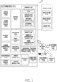
- FIG. 1 is a block diagram illustrating an electronic device 101 in a network environment 100 according to various embodiments.
- the electronic device 101 in the network environment 100 may communicate with an electronic device 102 via a first network 198 (e.g., a short-range wireless communication network), or an electronic device 104 or a server 108 via a second network 199 (e.g., a long-range wireless communication network).
- the electronic device 101 may communicate with the electronic device 104 via the server 108.
- the electronic device 101 may include a processor 120, memory 130, an input device 150, a sound output device 155, a display device 160, an audio module 170, a sensor module 176, an interface 177, a haptic module 179, a camera module 180, a power management module 188, a battery 189, a communication module 190, a subscriber identification module (SIM) 196, or an antenna module 197.
- at least one (e.g., the display device 160 or the camera module 180) of the components may be omitted from the electronic device 101, or one or more other components may be added in the electronic device 101.
- some of the components may be implemented as single integrated circuitry.
- the sensor module 176 e.g., a fingerprint sensor, an iris sensor, or an illuminance sensor
- the display device 160 e.g., a display
- an haptic module 179 e.g., a camera module 180
- a power management module 188 e.g., the display
- the processor 120 may execute, for example, software (e.g., a program 140) to control at least one other component (e.g., a hardware or software component) of the electronic device 101 coupled with the processor 120, and may perform various data processing or computation. According to one embodiment, as at least part of the data processing or computation, the processor 120 may load a command or data received from another component (e.g., the sensor module 176 or the communication module 190) in volatile memory 132, process the command or the data stored in the volatile memory 132, and store resulting data in non-volatile memory 134.
- software e.g., a program 140
- the processor 120 may load a command or data received from another component (e.g., the sensor module 176 or the communication module 190) in volatile memory 132, process the command or the data stored in the volatile memory 132, and store resulting data in non-volatile memory 134.
- the processor 120 may include a main processor 121 (e.g., a central processing unit (CPU) or an application processor (AP)), and an auxiliary processor 123 (e.g., a graphics processing unit (GPU), an image signal processor (ISP), a sensor hub processor, or a communication processor (CP)) that is operable independently from, or in conjunction with, the main processor 121.
- auxiliary processor 123 may be adapted to consume less power than the main processor 121, or to be specific to a specified function.
- the auxiliary processor 123 may be implemented as separate from, or as part of the main processor 121.
- the auxiliary processor 123 may control at least some of functions or states related to at least one component (e.g., the display device 160, the sensor module 176, or the communication module 190) among the components of the electronic device 101, instead of the main processor 121 while the main processor 121 is in an inactive (e.g., sleep) state, or together with the main processor 121 while the main processor 121 is in an active state (e.g., executing an application).
- the auxiliary processor 123 e.g., an image signal processor or a communication processor
- the memory 130 may store various data used by at least one component (e.g., the processor 120 or the sensor module 176) of the electronic device 101.
- the various data may include, for example, software (e.g., the program 140) and input data or output data for a command related thereto.
- the memory 130 may include the volatile memory 132 or the non-volatile memory 134.
- the input device 150 may receive a command or data to be used by other component (e.g., the processor 120) of the electronic device 101, from the outside (e.g., a user) of the electronic device 101.
- the input device 150 may include, for example, a microphone, a mouse, a keyboard, or a digital pen (e.g., a stylus pen).
- the sound output device 155 may output sound signals to the outside of the electronic device 101.
- the sound output device 155 may include, for example, a speaker or a receiver.
- the speaker may be used for general purposes, such as playing multimedia or playing record, and the receiver may be used for an incoming calls. According to an embodiment, the receiver may be implemented as separate from, or as part of the speaker.
- the display device 160 may visually provide information to the outside (e.g., a user) of the electronic device 101.
- the display device 160 may include, for example, a display, a hologram device, or a projector and control circuitry to control a corresponding one of the display, hologram device, and projector.
- the display device 160 may include touch circuitry adapted to detect a touch, or sensor circuitry (e.g., a pressure sensor) adapted to measure the intensity of force incurred by the touch.
- the audio module 170 may convert a sound into an electrical signal and vice versa. According to an embodiment, the audio module 170 may obtain the sound via the input device 150, or output the sound via the sound output device 155 or a headphone of an external electronic device (e.g., an electronic device 102) directly (e.g., wiredly) or wirelessly coupled with the electronic device 101.
- an external electronic device e.g., an electronic device 102
- directly e.g., wiredly
- wirelessly e.g., wirelessly
- the sensor module 176 may detect an operational state (e.g., power or temperature) of the electronic device 101 or an environmental state (e.g., a state of a user) external to the electronic device 101, and then generate an electrical signal or data value corresponding to the detected state.
- the sensor module 176 may include, for example, a gesture sensor, a gyro sensor, an atmospheric pressure sensor, a magnetic sensor, an acceleration sensor, a grip sensor, a proximity sensor, a color sensor, an infrared (IR) sensor, a biometric sensor, a temperature sensor, a humidity sensor, or an illuminance sensor.
- a connecting terminal 178 may include a connector via which the electronic device 101 may be physically connected with the external electronic device (e.g., the electronic device 102).
- the connecting terminal 178 may include, for example, a HDMI connector, a USB connector, a SD card connector, or an audio connector (e.g., a headphone connector).
- the haptic module 179 may convert an electrical signal into a mechanical stimulus (e.g., a vibration or a movement) or electrical stimulus which may be recognized by a user via his tactile sensation or kinesthetic sensation.
- the haptic module 179 may include, for example, a motor, a piezoelectric element, or an electric stimulator.
- the camera module 180 may capture a still image or moving images.
- the camera module 180 may include one or more lenses, image sensors, image signal processors, or flashes.
- the power management module 188 may manage power supplied to the electronic device 101.
- the power management module 188 may be implemented as at least part of, for example, a power management integrated circuit (PMIC).
- PMIC power management integrated circuit
- the battery 189 may supply power to at least one component of the electronic device 101.
- the battery 189 may include, for example, a primary cell which is not rechargeable, a secondary cell which is rechargeable, or a fuel cell.
- the communication module 190 may include a wireless communication module 192 (e.g., a cellular communication module, a short-range wireless communication module, or a global navigation satellite system (GNSS) communication module) or a wired communication module 194 (e.g., a local area network (LAN) communication module or a power line communication (PLC) module).
- a wireless communication module 192 e.g., a cellular communication module, a short-range wireless communication module, or a global navigation satellite system (GNSS) communication module
- GNSS global navigation satellite system
- wired communication module 194 e.g., a local area network (LAN) communication module or a power line communication (PLC) module.
- LAN local area network
- PLC power line communication
- a corresponding one of these communication modules may communicate with the external electronic device via the first network 198 (e.g., a short-range communication network, such as Bluetooth TM , wireless-fidelity (Wi-Fi) direct, or infrared data association (IrDA)) or the second network 199 (e.g., a long-range communication network, such as a cellular network, the Internet, or a computer network (e.g., LAN or wide area network (WAN)).
- the first network 198 e.g., a short-range communication network, such as Bluetooth TM , wireless-fidelity (Wi-Fi) direct, or infrared data association (IrDA)
- the second network 199 e.g., a long-range communication network, such as a cellular network, the Internet, or a computer network (e.g., LAN or wide area network (WAN)
- These various types of communication modules may be implemented as a single component (e.g., a single chip), or may be implemented as multi
- the wireless communication module 192 may identify and authenticate the electronic device 101 in a communication network, such as the first network 198 or the second network 199, using subscriber information (e.g., international mobile subscriber identity (IMSI)) stored in the subscriber identification module 196.
- subscriber information e.g., international mobile subscriber identity (IMSI)
- the antenna module 197 may transmit or receive a signal or power to or from the outside (e.g., the external electronic device) of the electronic device 101.
- the antenna module 197 may include an antenna including a radiating element composed of a conductive material or a conductive pattern formed in or on a substrate (e.g., a printed circuit board (PCB)).
- the antenna module 197 may include a plurality of antennas. In such a case, at least one antenna appropriate for a communication scheme used in the communication network, such as the first network 198 or the second network 199, may be selected, for example, by the communication module 190 (e.g., the wireless communication module 192) from the plurality of antennas.
- the signal or the power may then be transmitted or received between the communication module 190 and the external electronic device via the selected at least one antenna.
- another component e.g., a radio frequency integrated circuit (RFIC)
- RFIC radio frequency integrated circuit
- At least some of the above-described components may be coupled mutually and communicate signals (e.g., commands or data) therebetween via an inter-peripheral communication scheme (e.g., a bus, general purpose input and output (GPIO), serial peripheral interface (SPI), or mobile industry processor interface (MIPI)).
- an inter-peripheral communication scheme e.g., a bus, general purpose input and output (GPIO), serial peripheral interface (SPI), or mobile industry processor interface (MIPI)
- the electronic device may be one of various types of electronic devices.
- the electronic devices may include, for example, a portable communication device (e.g., a smartphone), a computer device, a portable multimedia device, a portable medical device, a camera, a wearable device, or a home appliance. According to an embodiment of the disclosure, the electronic devices are not limited to those described above.
- Various embodiments as set forth herein may be implemented as software including one or more instructions that are stored in a storage medium that is readable by a machine.
- a processor of the machine may invoke at least one of the one or more instructions stored in the storage medium, and execute it, with or without using one or more other components under the control of the processor. This allows the machine to be operated to perform at least one function according to the at least one instruction invoked.
- the one or more instructions may include a code generated by a complier or a code executable by an interpreter.
- the machine-readable storage medium may be provided in the form of a non-transitory storage medium.
- non-transitory simply means that the storage medium is a tangible device, and does not include a signal (e.g., an electromagnetic wave), but this term does not differentiate between where data is semi-permanently stored in the storage medium and where the data is temporarily stored in the storage medium.
- a signal e.g., an electromagnetic wave
- a method may be included and provided in a computer program product.
- the computer program product may be traded as a product between a seller and a buyer.
- the computer program product may be distributed in the form of a machine-readable storage medium (e.g., compact disc read only memory (CD-ROM)), or be distributed (e.g., downloaded or uploaded) online via an application store (e.g., PlayStore TM ), or between two user devices (e.g., smart phones) directly. If distributed online, at least part of the computer program product may be temporarily generated or at least temporarily stored in the machine-readable storage medium, such as memory of the manufacturer's server, a server of the application store, or a relay server.
- CD-ROM compact disc read only memory
- an application store e.g., PlayStore TM
- two user devices e.g., smart phones
- each component e.g., a module or a program of the above-described components may include a single entity or multiple entities. One or more of the above-described components may be omitted, or one or more other components may be added. Alternatively or additionally, a plurality of components (e.g., modules or programs) may be integrated into a single component. In such a case, the integrated component may still perform one or more functions of each of the plurality of components in the same or similar manner as they are performed by a corresponding one of the plurality of components before the integration. Operations performed by the module, the program, or another component may be carried out sequentially, in parallel, repeatedly, or heuristically, or one or more of the operations may be executed in a different order or omitted, or one or more other operations may be added.
- FIG. 2 is a diagram 200 of the program 140, according to an embodiment.
- the program 140 can include the OS 142 for controlling one or more resources relating to the electronic device 101, the middleware 144, or the application 146 running on the OS 142.
- the OS 142 can include, for example, Android TM , iOS TM , Windows TM , Symbian TM , Tizen TM , or Bada TM .
- At least part of the program 140 can be preloaded on an electronic device or can be downloaded from an external electronic device (e.g., the electronic device 102, 104, or the server 108).
- the OS 142 can control a management (e.g., allocation or retrieval) of one or more system resources (e.g., process, memory, or power).
- the OS 142 can include one or more driver programs for driving another hardware device of the electronic device 101 (e.g.,, the input device 150, the sound output device 155, the display device 160, the audio module 170, the sensor module 176, the interface 177, the haptic module 179, the camera module 180, the power management module 188, the battery 189, the communication module 190, the SIM 196, or the antenna module 197).
- the middleware 144 can provide various functions to the application 146 in order to allow the application 146 to efficiently use a function or information provided from one or more resources.
- the middleware 144 includes at least one of an application manager 201, a window manager 203, a multimedia manager 205, a resource manager 207, a power manager 209, a database manager 211, a package manager 213, a connectivity manager 215, a notification manager 217, a location manager 219, a graphic manager 221, a security manager 223, a telephony manager 225, or a voice recognition manage 227.
- the application manager 201 can manage the life cycle of the application 146.
- the window manager 203 can manage a GUI resource used in a screen.
- the multimedia manager 205 can recognize a format for playing various media files and encode or decode a media file by using the codec in a corresponding format.
- the resource manager 207 can manage a source code of the application 146 or a memory space of the memory 130.
- the power manager 209 can manage the capacity, temperature or power of the battery 189 and provide power information for an operation of the electronic device.
- the power manager 209 can operate together with a basic input/output system (BIOS).
- BIOS basic input/output system
- the database manager 211 can create, search, or modify a database used in the application 146.
- the package manager 213 can manage installation or updating of an application distributed in a package file format.
- the connectivity manger 215 can manage a wireless connection or a direct connection with an external electronic device.
- the notification manager 217 can provide an event, such as incoming messages, appointments, and proximity alerts, to the user.
- the location manager 219 can manage location information of an electronic device.
- the graphic manager 211 can manage a graphic effect to be provided to the user or a user interface relating thereto.
- the security manager 223 can provide system security or user authentication.
- the telephony manager 225 can manage a voice or video call function of the electronic device.
- the voice recognition manage 227 can transmit voice data of the user to the server 108, and receive a command corresponding to a function which the electronic device performs based on the voice data, or text data transformed based on the voice data.
- the middleware 144 can dynamically delete part of the existing components or add new components. At least a portion of the middleware 144 can be included in a portion of the OS 142 or can be implemented by another software different from the OS 142.
- the application 146 can include at least one of a home 251, a dialer 253, an SMS/multimedia messaging system (MMS) 255, an instant message (IM) 257, a browser 259, a camera 261, an alarm 263, a contact 265, a voice dialer 267, an e-mail 269, a calendar 271, a media player 273, an album 275, a watch 277, health 279 (e.g., measure an exercise amount or blood sugar level), or environmental information 281 (e.g., air pressure, humidity, or temperature information) application.
- the application 146 can include an information exchange application for supporting information exchange between the electronic device and an external electronic device.
- the information exchange application can include a notification relay application for relaying specific information to the external device or a device management application for managing the external electronic device.
- the notification relay application can relay notification information from another application of the electronic device to an external electronic device, or receive and forward notification information from an external electronic device to the user.
- the device management application can install, delete, or update a function (e.g., turn-on/turn off of the external electronic device itself (or some components) or display brightness (or resolution) adjustment) of an external electronic device communicating with the electronic device, or an application operating in the external electronic device.
- a function e.g., turn-on/turn off of the external electronic device itself (or some components) or display brightness (or resolution) adjustment
- FIG. 3A is a diagram of an electronic device and external display, according to an embodiment
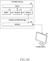
- FIG. 3B is a diagram of an electronic device and an external display, according to an embodiment.
- the electronic device 101 and elements included in the electronic device 101 in FIGS. 3A and 3B may correspond to the electronic device 101 and the elements included in the electronic device 101 of FIG. 1 .
- the electronic device 101 may correspond to any one of a smartphone, a smart pad, a tablet PC, and a PDA.
- the electronic device 101 may be designed to allow a user to easily carry the electronic device 101.
- the electronic device 101 may include a processor 120.
- the processor 120 may calculate data by using one or more instructions.
- the processor 120 may include at least one of an arithmetic logical unit (ALU), a field programmable gate array (FPGA), an integrated circuit (IC), and a large scale integration (LSI) which are used to calculate data.
- ALU arithmetic logical unit
- FPGA field programmable gate array
- IC integrated circuit
- LSI large scale integration
- the electronic device 101 may include a memory 130 storing one or more applications or data which may be executed by the processor 120.
- the memory 130 may include at least one of a volatile memory or a nonvolatile memory used by the electronic device 101.
- the volatile memory may correspond to a static random access memory (SRAM) or a dynamic RAM (DRAM). Data stored in the nonvolatile memory may not be deleted even when power supplied to the electronic device 101 is stopped.
- the nonvolatile memory may correspond not only to a magnetoresistive RAM (MRAM), a spin-transfer torque MRAM (STT-MRAM), a phase-change RAM (PRAM), a resistive RAM (RRAM), a ferroelectric RAM (FeRAM), but also to a flash memory, an embedded multi media card (eMMC), a solid state drive (SSD).
- MRAM magnetoresistive RAM
- STT-MRAM spin-transfer torque MRAM
- PRAM phase-change RAM
- RRAM resistive RAM
- FeRAM ferroelectric RAM
- flash memory an embedded multi media card (eMMC), a solid state drive (SSD).
- SSD solid state drive
- the memory 120 may store an instruction related to an application and an instruction related to an OS.
- the OS refers to system software executed by the processor 120.
- the electronic device 101 may manage hardware components included in the electronic device 101 by executing the OS.
- the OS may provide an application programming interface (API) to an application which is software other than system software.
- API application programming interface
- a UI outputted through the display 320 may be generated by an application which is executed in the processor 120.
- the electronic device 101 may include a touch screen panel (TSP) disposed on the display 320 to allow the user to intuitively control the UI outputted through the display 320.
- the touch screen panel may detect a position of an object (e.g., a user's finger, a stylus) which touches the display 320 or hovers above the display 320 by using at least one of a resistive film, a capacitive component, a surface acoustic wave, and infrared rays.
- the electronic device 101 may be directly connected with an external electronic device (e.g., the external display 310) through an interface 177.
- the interface 177 may include an HDMI, a USB interface.
- the processor 120, the memory 130, the display 320, and the interface 177 may be operatively coupled to one another.
- the processor 120, the memory 130, the display 320, and the interface 177 may be electrically connected with one another by a communication bus.
- the external display 310 may visually output information to a user by using at least one of an OLED, an LCD, and an LED.
- the external display 310 may include a display driver IC (DDI) for controlling pixels constituted by using at least one of an OLED, an LCD, and an LED.
- the external display 310 or the DDI may be directly controlled by the processor 120 of the electronic device 101.
- the DDI of the external display 310 may control the respective pixels based on information corresponding to a UI generated in the processor 120 of the electronic device 101.
- the electronic device 101 and the external display 310 may be connected with each other by an external electronic device 330.
- the external electronic device 330 may include an interface 335 relaying a flow of an electric signal between the electronic device 101 and the external display 310.
- the number of pieces of hardware e.g., the external display 310, a keyboard, a mouse
- information corresponding to a UI generated in the processor 120 of the electronic device 101 may be transmitted to the external display 310 and the DDI through the interface 335.
- the processor 120 may obtain a second UI which is different from a first UI outputted in the display 320 and outputted to the external display 310, by using an application outputting the first UI to the display 320.
- the second UI may be outputted on the external display 310 in response to a connection between the electronic device 101 and the external display 310.
- the processor 120 may output the obtained second UI on the external display 310 in response to a user input related to the first UI outputted in the display 320.
- the user may receive the plurality of UIs generated in one application which is running in the processor 120, simultaneously, through the display 320 of the electronic device 101 and the external display 310.
- FIGS. 3A and 3B depict that the electronic device 101 and the external electronic device are connected with each other wiredly, various embodiments are not limited thereto.
- the electronic device 101 and the external electronic device may be connected with each other wirelessly.
- the electronic device 101 and the external electronic device may be connected with each other wirelessly based on at least one of Bluetooth, WiFi, digital living network alliance (DLNA).
- DLNA digital living network alliance
- the operation of the processor 120 outputting the plurality of UIs generated in at least one application which is running in the processor 120 to the display 320 of the electronic device 101 and the external display 310, simultaneously, in response to the connection between the electronic device 101 and the external display 310 will be described in detail.
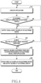
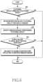
- FIG. 4 is a flowchart of a method of outputting a plurality of UIs identified from a running application to a display of the electronic device and an external display, respectively, according to an embodiment.
- the electronic device of FIG. 4 may correspond to the electronic device 101 of FIG. 1 and FIGS. 3A and 3B .
- the steps of FIG. 4 may be executed by the electronic device 101 of FIG. 1 and FIGS. 3A and 3B , or the processor 120 of the electronic device 101 of FIG. 1 and FIGS. 3A and 3B.
- the electronic device executes an application in response to a control by a user.
- the application is executed by a processor included in the electronic device. While the application is being executed, the electronic device outputs a first UI generated from the application in the display included in the electronic device (e.g., the display 320 of FIGS. 3A and 3B ). While the user is controlling the first UI (e.g., by touching a touch sensor formed on the display of the electronic device), the electronic may identify and process various events which are defined in the application in response to a control of the first UI.
- the electronic device detects a connection between an external display and the electronic device.
- Step 420 is performed by the processor of the electronic device while the application is being executed.
- the electronic device may detect the external display based on a plug and play (PnP) method.
- PnP plug and play
- the electronic device may output outputs the first UI and a visual object floated on the first UI in the display of the electronic device by using the running application at step 430.
- the visual object is related to the external display.
- the visual object may correspond to a function of allowing the running application to control the display of the electronic device and the external display simultaneously.
- the visual object may correspond to a function of switching an operation mode of the application into an operation mode for using the display of the electronic device and the external display simultaneously (e.g., a dual mode). Whether the visual object is outputted on the first UI may depend on whether the application running in the electronic device supports the operation mode for using the display of the electronic device and the external display simultaneously.
- the electronic device may detect a first input related to the visual object from the user at step 440.
- the visual object may have a text message floated on the first UI, a button-shaped icon, or a form of an image object on the display of the electronic device.
- the first input may correspond to a user's touch input which occurs in a region corresponding to the visual object floated on the first UI.
- the electronic device When the first input related to the visual object is received from the user, the electronic device identifies a second UI different from the first UI outputted in the display of the electronic device from the running application at step 450.
- the electronic device may identify the second UI generated by the application based on the size of the external display.
- the electronic device outputs the first UI on the display of the electronic device and outputs the identified second UI to the external display. While outputting the first UI on the display of the electronic device, the electronic device outputs the identified second UI on the external display.
- a configuration of a display of the first UI may be different from a configuration of a display of the second UI. Both the first UI and the second UI may be generated by the application which is executed in the processor of the electronic device.
- the electronic device may change the display of the first UI.
- the display of the second UI may be maintained independently from the reception of the second input.
- a user input on any one interface of the first UI or the second UI may be used to change the display of both the first UI and the second UI.
- FIG. 5A is a diagram of an example in which an electronic device outputs a first UI and a second UI obtained from an application to a display of the electronic device and an external display, respectively, according to an embodiment.
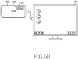
- FIG. 5B is a diagram of an example in which the electronic device outputs the first UI and the second UI obtained from the application to the display of the electronic device and the external display, respectively, according to an embodiment.
- FIG. 5C is a diagram of an example in which the electronic device outputs the first UI and the second UI obtained from the application to the display of the electronic device and the external display, respectively, according to an embodiment.
- the electronic device 101 of FIGS. 5A , 5B , and 5C may be related to the electronic device 101 of FIG. 1 and FIG.
- Steps of the electronic device 101 of FIGS. 5A , 5B , and 5C may be related to the steps of FIG. 4 .
- the external display of FIGS. 5A , 5B , and 5C may be related to the external display 310 of FIGS. 3A and 3B .
- the electronic device 101 may output the first UI 510 identified from the application in the display of the electronic device 101.
- the application outputting the first UI 510 in the display of the electronic device 101 may be executed by a user or an operating system.
- the user may control the application running in the electronic device 101 by using the first UI 510.
- the external display 310 may operate independently from the electronic device 101.
- a state of the external display 310 may correspond to an idle state in which the external display 310 waits for a signal from a processor (e.g., the processor of the electronic device 101) existing outside the external display 310.
- the electronic device 101 may control the external display 310 and the display of the electronic device 101 simultaneously.
- the electronic device 101 controlling the external display 310 and the display of the electronic device 101 simultaneously may be related to step 420 of FIG. 4 or steps after step 420.
- the electronic device 101 may output a UI for allowing the user to select a mode of the external display from (1) a mirroring mode in which an image of the display of the electronic device 101 is displayed as it is, or (2) a desktop mode in which an image different from the display of the electronic device 101 is displayed and a workspace of the display of the electronic device 101 is extended.
- the electronic device 101 may output a UI (e.g., a home screen generated based on a size or a type of the external display 310) for selecting an application to be executed in the external display 310 on the external display 310, based on an operating system running in the electronic device 101.
- a UI e.g., a home screen generated based on a size or a type of the external display 310
- the UI outputted on the external display 310 based on the operating system executed by the electronic device 101 may include a list of applications based on visual objects (e.g., icons or thumbnails) corresponding to one or more applications installed in the electronic device 101.
- the electronic device 101 may inform the application outputting the first UI 510 that the electronic device 101 and the external display 310 are connected with each other, based on the operating system running in the electronic device 101.
- the electronic device 101 may invoke or execute an event related to the connection between the electronic device 101 and the external display 310 among events defined in the application.
- the electronic device 101 may output a visual object 520 designated by the running application on the first UI 510 outputted in the display of the electronic device 101.
- the visual object 520 may occupy a designated region of the display of the electronic device 101 regardless of whether the first UI 510 is changed.
- the electronic device 101 may output the visual object 520 on the first UI 510 based on step 430 of FIG. 4 .
- the visual object 520 may include a text message or an icon informing the user that it is possible to control the application by using the display of the electronic device 101 and the external display 310 simultaneously.
- the electronic device 101 may control both the display 320 of the electronic device 101 and the external display 310 based on the first UI 510 and the second UI 530 generated from the application running in the electronic device 101.
- the second UI 530 may be identified from the application running in the electronic device 101, based on step 450 of FIG. 4 .
- the electronic device 101 may generate the second UI 530 based on the application related to the first UI 510 and information related to the external display 310.
- the electronic device 101 may output the first UI 510 and the second UI 530 identified from one application to the display of the electronic device 101 and the external display 310, respectively and simultaneously.
- the second UI 530 may be outputted on the external display 310 and may be floated on a UI generated based on the operating system of the electronic device 101.
- the electronic device 101 may arrange different visual objects on the first UI 510 and the second UI 530 according to different layouts.
- the visual object 520 may include a text message or an icon informing that it is possible to control the application only by the display of the electronic device 101 without the external display 310.
- the user may change the state of the application running in the electronic device 101 to a previous state before the second UI 530 is generated on the external display 310 by touching the visual object 520.
- the electronic device 101 may discard the second UI 530 outputted in the external display 310 from the external display 310.
- the visual object 520 may be outputted in response to the connection between the electronic device 101 and the external display 310, and may allow the application running in the electronic device 101 to toggle between a first state in which only the first UI 510 is outputted, and a second state in which the first UI 510 and the second UI 530 are outputted simultaneously.
- FIGS. 5A , 5B , and 5C illustrate the connection between the electronic device 101 and the external display 310 based on the embodiment illustrated in FIG. 3A
- various embodiments are not limited to the embodiment of FIGS. 5A , 5B , and 5C .
- the electronic device 101 and the external display 310 may operate similarly to those of FIGS. 5A , 5B , and 5C .
- FIG. 6 is a flowchart of a method of identifying, by an electronic device, a second UI based on information related to an external display, according to an embodiment.
- the electronic device of FIG. 6 may correspond to the electronic device 101 of FIG. 1 and FIGS. 3A , and 3B . Steps of FIG. 6 may be performed by the electronic device 101 of FIG. 1 and FIGS. 3A , and 3B or the processor 120 of the electronic device 101 of FIG. 1 and FIGS. 3A and 3B . The steps of FIG. 6 may be performed based on an operating system or system software which is running in the electronic device 101.
- the electronic device may detect a connection between the external display and the electronic device.
- Step 605 may correspond to step 420 of FIG. 4 .
- the electronic device may obtain information related to the external display from a display manager, which is a process or middleware executed by the operating system, at step 610.
- the display manager may be included as a part of the graphic manager 221 of FIG. 2 .
- the information related to the external display may include a value related to at least one of a size of the external display, a resolution of the external display, and pixel per inch (ppi) of the external display.
- the electronic device may identify a window manager corresponding to the external display.
- the window manager may correspond to the window manager 203 of FIG. 2 .
- the window manager may be a process or middleware that is generated based on the size or resolution of the external display, and is managed by the operating system.
- the window managers for the display of the electronic device and the external display may be independently executed.
- the window managers for the display of the electronic device and the external display may be executed in the processor of the electronic device based on processes independent from one another.
- Steps 610 and 620 may be performed at the same as step 430 of FIG. 4 . While step 610 or 620 is performed, the electronic device may output a visual object (e.g., the visual object 520 of FIG. 5B ) for controlling the application by using the display of the electronic device and the external display simultaneously on the first UI generated by the running application.
- a visual object e.g., the visual object 520 of FIG. 5B
- the electronic device may detect an input related to the visual object from the user at step 625.
- Step 625 may correspond to step 440 of FIG. 4 .
- the electronic device may add an object included in the second UI identified from the application to the window manager identified based on step 620.
- the electronic device may provide the identified window manager to the application.
- the second UI may be identified from the application running in the electronic device based on step 450 of FIG. 4 .
- the object included in the second UI may correspond to a view object which is a basic unit constituting a visual object in the Android operating system, or may be an object inheriting the view object.
- the second UI may include a canvas including the entire multimedia content included in the first UI.
- the electronic device may output the object included in the second UI, added to the window manager, in the external display corresponding to the window manager. Based on the visual object inputted to the window manager by the application, the electronic device may identify the second UI to be outputted to the external display.
- the window manager corresponding to the external display may be removed when the application is terminated, the connection between the external display and the electronic device is terminated, or the user terminates controlling the application by using the display of the electronic device and the external display simultaneously (e.g., when the user toggles the visual object 520 of FIGS. 5B and 5C ).
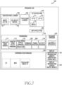
- FIG. 7 is a diagram 700 of a program executed in an electronic device, according to an embodiment.
- the electronic device may include at least one of a touch mode launcher 760 or a desktop mode launcher 750 for generating a UI (e.g., a home screen or a desktop) to allow the user to select one or more functions supported in the electronic device after a booting operation is performed by an operating system.
- the UI generated by the touch mode launcher 760 or the desktop mode launcher 750 may include a list of one or more applications (e.g., a first application 770, a second application 780) installed in the electronic device.
- a touch mode and a desktop mode which is a part of designated operation modes of the electronic device are designated modes that are used to determine a layout of a UI or a window to be outputted through the display.
- the touch mode and the desktop mode may be set according to each of one or more displays connected with the electronic device.
- the touch mode and the desktop mode may be switched based on a user input.
- the electronic device may determine an operation mode corresponding to a touch screen to the touch mode, and may generate a UI to be outputted through the touch screen based on a layout through which a user's touch input can be easily received.
- the electronic device may determine an operation mode corresponding to a display that does not include a touch screen, such as an external display, to the desktop mode, and may generate a UI to be outputted through the display based on a layout through which a keyboard or mouse input of a user can be easily received.
- a touch screen such as an external display
- the electronic device may output a UI for providing a user experience related to a touch sensor coupled to the display on the display of the electronic device.
- the UI outputted based on the touch mode launcher 760 may provide usability similar to a smartphone or a smart pad to the user.
- the electronic device may output a UI for providing a user experience related to a keyboard or a mouse on the external display.
- the UI outputted based on the desktop mode launcher 750 may provide usability similar to a desktop PC to the user.
- the electronic device may obtain a UI to be outputted on the display of the electronic device from the touch mode launcher 760, and may obtain a UI to be outputted on the external display from the desktop mode launcher 750.
- the electronic device may output the UI obtained from the touch mode launcher 760 and the UI obtained from the desktop mode launcher 750 to the display of the electronic device and the external display, respectively and simultaneously.
- the list of applications installed in the electronic device may be displayed on both the display of the electronic device and the external display.
- the desktop mode launcher 750 may include a white list database (DB) 751 and a DB update service 752 for managing information of the white list DB 751.
- the white list DB 751 may include a list of applications supporting changing (resizing) of a size of a window or a UI among the applications installed in the electronic device.
- the whist list DB 751 may include a list of applications which can be executed in the desktop mode without breaking a layout.
- the list of applications may be based on names of the applications or names of packages corresponding to the applications.
- the DB update service 752 may update the white list DB 751 based on a server connected to the electronic device.
- the DB update service 752 may receive information necessary for updating the white list DB 751 from the server through a desktop mode policy manager 712.
- the electronic device may identify a UI to be outputted on the display of the electronic device based on the selected application.
- the identified UI may have a layout based on the touch mode.
- the electronic device may identify a UI to be outputted on the external display based on the selected application.
- the identified UI may have a layout based on the desktop mode.
- the electronic device may identify a UI to be outputted to the display of the electronic device or the external display, based on at least one of a first UI 771, a second UI 772, and a third UI 773 which are defined in the first application 770.
- Each of the first UI 771, the second UI 772, and the third UI 773 may correspond to an activity of the Android operating system.
- Each of the first UI 771, the second UI 772, and the third UI 773 may have a layout based on any one of a landscape mode or a portrait mode according to an orientation of the display.
- the electronic device may output the first UI 771 on the display of the electronic device and may output the second UI 772 on the external display.
- the electronic device may output a part of the first UI 771 on the display of the electronic device and may output the other part of the first UI 771 on the external display.
- the electronic device may output a part of the first UI 771 on the display of the electronic device, and may output the entire first UI 771 on the external display.
- the electronic device may provide a function or information provided from one or more resources of the electronic device to an application installed in the electronic device, by using a framework 710.
- the applications installed in the electronic device such as the first application 770, the desktop mode launcher 750, and the touch mode launcher 760 may obtain a function or information of the electronic device through the framework 710.
- the framework 710 may correspond to at least a part of the middleware 144 of FIG. 2 .
- the electronic device may obtain information related to an operation in the desktop mode from an application which is expected to be executed according to user's selection.
- the electronic device may identify whether the application will be executed based on a static window, whether the application will be executed based on a freeform window, whether change of an orientation is supported, or whether resizing is supported, by using the desktop mode service 711.
- the electronic device may determine whether the application that is expected to be executed is included in the white list DB 751, and then the electronic device may identify whether an application will be executed based on a static window, whether an application will be executed based on a freeform window, whether change of an orientation is supported, or whether resizing is supported, according to each application from the desktop mode policy manager 712.
- the electronic device may change display configuration information 730 and display information 740, and may transmit the changed information to the application. Since the electronic device changes the display configuration information 730 and the display information 740 which are based on a real size of the display, and transmits the changed information to the application, an error in processing a layout or in processing a touch input, which may occur in the application, can be prevented.
- the display configuration information 730 may include values related to a density, an orientation, screen size information (width, height) of the display, and the display information 740 may include values related to logical width, logical height.
- the electronic device may obtain information related to an operation in the touch mode from an application which is expected to be executed according to user's selection. Based on a window manager 203, the electronic device may output a UI obtained from an application on the display. Based on a power manager 209, the electronic device may perform power management of the electronic device. Based on an activity manager 714, the electronic device may manage a UI generated in one or more running applications on a basis of an activity. Based on a communication manager 720, the electronic device may manage a communication means for connecting the electronic device to another electronic device.
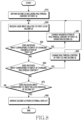
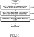
- FIG. 8 is a flowchart of a method of processing, by an electronic device, a user input received from a first UI and a second UI outputted to a plurality of displays, respectively, according to an embodiment.
- the electronic device of FIG. 8 may correspond to the electronic device of FIG. 1 and FIGS. 3A and 3B . Steps of FIG. 8 may be executed by the electronic device of FIG. 1 and FIGS. 3A and 3B , or the processor 120 of the electronic device 101 of FIG. 1 and FIGS. 3A and 3B . The steps of FIG. 8 may be related to step 460 of FIG. 4 .
- the electronic device may receive a user input related to the first UI or the second UI.
- the user input related to the first UI may correspond to a gesture of touching a specific region of the touch sensor or a gesture of rubbing at least a part of the touch sensor.
- a user input related to the second UI may correspond an action (e.g., clicking, dragging, inputting a text) performed on an object outputted through the second UI by using a mouse or keyboard connected to the electronic device.
- the electronic device may identify an event corresponding to the received input among a plurality of events defined in the application.
- Step 830, step 850, and step 870 may be related to an operation of the electronic device identifying an event corresponding to a received input among a plurality of events defined in the application.
- the order of executing step 830, step 850, and step 870 by the electronic device is not limited to the order illustrated in FIG. 8 .
- Step 830, step 850, and step 870 may be performed by the electronic device simultaneously.
- the electronic device may determine whether the received input corresponds to an input of changing a magnification of the first UI.
- a designated gesture e.g., a pinch-to-zoom gesture
- the electronic device may determine that the received input corresponds to an input of changing the magnification of the first UI.
- the electronic device may change a magnification of a multimedia content outputted through the first UI at step 840.
- a magnification of the multimedia content outputted through the second UI may be maintained while the magnification of the multimedia content outputted through the first UI is changed.
- the step of the electronic device changing the magnification of the multimedia content will be described in detail with reference to FIGS. 9A , 9B , 9C , and 9D .
- the electronic device may determine whether the received input corresponds to an input of changing the multimedia content.
- a gesture e.g., a drag gesture
- the electronic device may determine that the received input corresponds to the input of changing the multimedia content.
- the electronic device may change the multimedia content of the first UI and the second UI based on the user input at step 860.
- the step of the electronic device changing the multimedia content based on the user input will be described in detail with reference to FIG. 10 and FIGS. 11A and 11B .
- the electronic device may determine whether the received input corresponds to an input related to removal of the second UI.
- the electronic device may determine that the received input corresponds to the input related to the removal of the second UI.
- the electronic device may remove the second UI from the external display at step 880.
- the electronic device may change an image outputted on the external display from an image corresponding to the second UI to an image corresponding to the UI (e.g., a home screen or a desktop screen) identified from the operating system. While the second UI is removed from the external display, the first UI outputted on the display of the electronic device may be maintained.
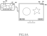
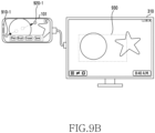
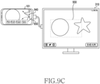
- FIG. 9A is a diagram of an example in which, in response to a user input, an electronic device changes a magnification of a multimedia content displayed on a first UI while maintaining a magnification of a multimedia content displayed on a second UI, according to an embodiment.
- FIG. 9B is a diagram of an example in which, in response to the user input, the electronic device changes the magnification of the multimedia content displayed on the first UI while maintaining the magnification of the multimedia content displayed on the second UI, according to an embodiment.
- FIG. 9C is a diagram of an example in which, in response to the user input, the electronic device changes the magnification of the multimedia content displayed on the first UI while maintaining the magnification of the multimedia content displayed on the second UI, according to an embodiment.
- FIG. 9A is a diagram of an example in which, in response to a user input, an electronic device changes a magnification of a multimedia content displayed on a first UI while maintaining a magnification of a multimedia content displayed on
- FIG. 9D is a diagram of an example in which, in response to the user input, the electronic device changes the magnification of the multimedia content displayed on the first UI while maintaining the magnification of the multimedia content displayed on the second UI, according to an embodiment.
- the electronic device 101 of FIGS. 9A , 9B , 9C , and 9D may be related to the electronic device 101 of FIGS. 1 and 3A .
- Operations of FIGS. 9A , 9B , 9C , and 9D may be related to at least one of the steps of FIG. 4 , FIG. 6 , or FIG. 8 .
- An external display of FIGS. 9A , 9B , 9C , and 9D may be related to the external display 310 of FIGS. 3A and 3B .
- the electronic device 101 may output a first UI and a second UI obtained from a running application to the display of the electronic device 101 and the external display 310, respectively.
- the operation of the electronic device 101 obtaining the first UI and the second UI to be outputted to the display of the electronic device 101 and the external display 310, respectively, from one application, may be performed based on at least one of step 810 of FIG. 8 , step 460 of FIG. 4 , or the steps of FIG. 6 .
- the electronic device 101 may output a visual object 903 which is displayed on the second UI outputted on the external display 310 to change the size of the second UI to any one of designated sizes.
- the visual object 903 may include at least one of a minimize button to reduce the size of the second UI to a minimum size guaranteeing usability, a maximize button to enlarge the size of the second UI to the full size of the external display 310, an exit button to exit from the second UI or the application, and a restore button to restore a state of the second UI or the application to a previous state before a final user input.
- the electronic device 101 may output a warming message.
- a designated threshold e.g. 400 MB
- the electronic device 101 may enlarge the size of the second UI to a maximum size that has a size ratio of the second UI executed in the portrait mode in the external display.
- configurations of the first UI and the second UI generated from one application running in the electronic device 101 may be different from each other.
- the first UI outputted on the display of the electronic device 101 may include one or more visual objects (e.g., a pen tool, a brush tool, an eraser tool, a save button) for changing the multimedia content.
- the second UI may have a layout for outputting the entire multimedia content.
- the first UI and the second UI may output one multimedia content at different magnifications.
- the electronic device 101 may determine whether a user's gesture corresponds to a gesture for changing the magnification (e.g., a pinch-to-zoom gesture). In response to the gesture for changing the magnification being received, the electronic device 101 may determine a UI on which the gesture is performed among the first UI and the second UI as a UI whose magnification will be changed based on the received gesture.
- a gesture for changing the magnification e.g., a pinch-to-zoom gesture.
- the user of the electronic device 101 may perform the gesture for changing the magnification of the first UI on the first UI.
- the user may touch two regions 910, 920 on the display of the electronic device 101 with two fingers simultaneously, and then may increase a distance between the two fingers touching the two regions 910, 920 as indicated by the path shown in FIG. 9A (pinch-to-zoom gesture). Since the two regions 910, 920 on the display touched by the user correspond to the first UI, the electronic device 101 may determine to change the magnification of the first UI based on the user's gesture.
- the electronic device 101 may change the magnification of the multimedia content outputted in the first UI.
- the user may drag the two fingers from the two regions 910, 920 of FIG. 9A to two regions 910-1, 920-1 of FIG. 9B on the display of the electronic device 101.
- the magnification of the multimedia content outputted in the first UI is changed in response to the input of the user's gesture
- the magnification of the multimedia content outputted in the second UI of the external display 310 may be maintained.
- the electronic device 101 may output a part of the multimedia content through the first UI.
- a part of the multimedia content outputted through the first UI may correspond to a part 930 of the multimedia content outputted through the second UI.
- the electronic device 101 may enlarge the part 930 of the multimedia content outputted through the second UI and may output the part 930 on the first UI.
- a size of the part 930 may be determined based on a magnification corresponding to the user's gesture.
- the electronic device 101 may visually output which part of the multimedia content outputted in the second UI corresponds to the part of the multimedia content outputted in the first UI.
- the electronic device 101 may highlight the part 930 of the multimedia content outputted through the second UI by color or a figure, and may indicate which part of the multimedia content outputted in the second UI corresponds to the part of the multimedia content outputted in the first UI.
- FIGS. 9C and 9D a gesture of a different form from the gesture illustrated in FIGS. 9A and 9B is illustrated.
- the user may perform a pinch-to-zoom gesture of moving from starts point of two regions 940, 950 of FIG. 9C to end points of two regions 940-1, 950-1 of FIG. 9D .
- the user may move two fingers touching the display in one direction (a direction of moving toward the center of the display from the right border of the display) along paths shown in FIG. 9C .
- the user may increase a distance between the two fingers while moving the two fingers in one direction.
- the electronic device 101 may change the magnification of the first UI related to the gesture, and may shift a part of the multimedia content to be displayed through the first UI.
- a part of the multimedia content outputted through the first UI may correspond to the part 930 of the multimedia content outputted through the second UI.
- the electronic device 101 may output a part 960 of the multimedia content outputted through the second UI through the first UI as shown in FIG. 9D . Since the user increases the distance between the two fingers, the magnification of the multimedia content outputted through the first UI may increase. In addition, since the user moves the two fingers in one direction, a part of the multimedia content outputted through the first UI may be moved based on the moving direction of the two fingers.
- the electronic device may magnify/reduce or parallel move a part of the multimedia content outputted through the first UI while maintaining the display of the multimedia content outputted through the second UI in response to a user input performed in the first UI.
- the electronic device may rotate a part of the multimedia content outputted through the first UI while maintaining the display of the multimedia content outputted through the second UI in response to a user input performed in the first UI.
- the electronic device may rotate a part of the multimedia content outputted through the first UI.
- FIG. 10 is a flowchart of a method of executing, by an electronic device, an event defined in an application in response to a user input, according to an embodiment.
- the electronic device of FIG. 10 may correspond to the electronic device 101 of FIG. 1 and FIGS. 3A and 3B . Steps of FIG. 10 may be performed by the electronic device 101 of FIG. 1 and FIGS. 3A and 3B , or the processor 120 of the electronic device 101 of FIG. 1 and FIGS. 3A and 3B . The steps of FIG. 10 may be related to step 860 of FIG. 8 .
- the electronic device may identify a user input which is received in a first UI and a second UI to change a multimedia content.
- the first UI and the second UI may be obtained by an application which is running in the electronic device, and may be outputted to the display of the electronic device and the external display, respectively.
- FIGS. 11A and 11B A specific example of the user input for changing the multimedia content will be described in detail with reference to FIGS. 11A and 11B .
- the electronic device may execute an event corresponding to the identified user input in each of the first UI and the second UI at step 1020.
- the electronic device may execute an event corresponding to the user input among a plurality of events related to the first UI defined in the application.
- the electronic device may change the user input identified through the first UI based on the second UI and then may execute an event corresponding to the changed user input among a plurality of events related to the second UI defined in the application.
- the user input identified through the first UI may be processed by the first process.
- the electronic device may copy or intercept the user input identified through the first UI based on the second process.
- the electronic device may process the user input copied or intercepted based on the second process, based on an entire region of the multimedia content, such as a canvas view outputting the entire multimedia content, outputted through the second UI.
- the electronic device may process the identified user input based on the second process. While processing the identified user input based on the second process, the electronic device may copy or intercept the user input identified through the second UI, based on the first process.
- the electronic device may change the first UI and the second UI based on the executed events at step 1030.
- the display of the first UI outputted in the display of the electronic device, and the display of the second UI outputted in the external display may be changed based on the events executed in the first UI and the second UI respectively.
- the electronic device 101 may display a part of a multimedia content on the display of the electronic device 101 at a first magnification, by using an application executed by the processor of the electronic device 101.
- the electronic device 101 may display the multimedia content on the external display 310 at a second magnification different from the first magnification by using the application.
- the user may perform a gesture for changing the multimedia content by dragging on the display of the electronic device 101 with the finger or the stylus 1120.
- the user may touch a region 1130 of the display of the electronic device 101 with the stylus 1120 in a part of the multimedia content displayed in the first UI at the first magnification, and then may move the stylus 1120 along a path 1140.
- the user may release the stylus 1120 from the display in a region 1150 of the display of the electronic device 101.
- the electronic device 101 may display a visual object 1160 corresponding to the drag input in a part of the multimedia content displayed in the first UI at the first magnification.
- the visual object 1160 may have a shape corresponding to a stroke or path 1140 of the stylus 1120.
- thickness of the visual object 1160 may be related to a pressure by the stylus 1120 detected.
- the user of the electronic device 101 may control various parameters of the visual object 1160 (e.g., color of the stroke, thickness of the stroke, a shape of a start point or end point of the stroke).
- the electronic device 101 displaying the visual object 1160 may be performed by the steps of FIG. 10 .
- the electronic device 101 may display a visual object 1170 corresponding to the drag input in the multimedia content of the second UI outputted in the external display 310 at the same as displaying the visual object 1160 in the first UI.
- the visual object 1170 may have a shape corresponding to the path 1140 of the stylus 1120.
- the electronic device may obtain the visual object 1160 to be outputted through the first UI and the visual object 1170 to be outputted through the second UI from the application.
- the electronic device may superimpose the identified visual objects 1160, 1170 on the multimedia content based on different magnifications in the first UI and the second UI, respectively.
- the visual object 1160 and the visual object 1170 are generated in response to one drag input, the respective sizes of the visual object 1160 and the visual object 1170 may be different from each other.
- the respective sizes of the visual object 1160 and the visual object 1170 may have sizes corresponding to the first magnification and the second magnification, respectively.
- FIG. 12A is a diagram of another example of outputting, by an electronic device, a plurality of UIs obtained from an application to a display of the electronic device and an external display, according to an embodiment.
- FIG. 12B is a diagram of another example of outputting, by the electronic device, the plurality of UIs obtained from the application to the display of the electronic device and the external display, according to an embodiment.
- FIG. 12C is a diagram of another example of outputting, by the electronic device, the plurality of UIs obtained from the application to the display of the electronic device and the external display, according to an embodiment.
- the electronic device 101 of FIGS. 12A , 12B and 12C may be related to the electronic device 101 of FIG. 1 and FIG. 3A . Operations of the electronic device 101 of FIGS.
- the external display of the electronic device 101 of FIGS. 12A , 12B , and 12C may be related to the external display 310 of FIGS. 3A and 3B .
- the electronic device 101 may output a first UI identified from an application in the display of the electronic device 101.
- the user may control the application which is running in the electronic device 101 by using the first UI.
- the user may control the application by touching visual objects 1210, 1220 on the first UI.
- the visual objects 1210, 1220 may correspond to a controller for controlling movement of another visual object in the application.
- the electronic device 101 may control the display of the electronic device 101 and the external display 310 simultaneously.
- the electronic device 101 controlling the external display 310 and the display of the electronic device 101 simultaneously may be related to step 420 of FIG. 4 or steps after step 420.
- the electronic device 101 may output a UI for selecting an application to be executed in the external display 310 (e.g., a home screen generated based on a size or type of the external display 310) on the external display 310, based on an operating system which is running in the electronic device 101.
- the electronic device 101 may inform the application outputting the first UI of the connection between the electronic device 101 and the external display 310.
- the electronic device 101 may output, on the first UI, a visual object 1230 for obtaining determination of whether the user wishes to control the display of the electronic device 101 and the external display 310 simultaneously based on one application.
- the visual object 1230 may inform the user that the application can be controlled by using the display of the electronic device 101 and the external display 310 simultaneously, by using a text message, an icon, or a button.
- the electronic device 101 may control both the display of the electronic device 101 and the external display 310 based on the application related to the first UI.
- the application corresponds to game software
- the application outputs visual objects 1210-1, 1220-1 related to controlling by the user in the display of the electronic device 101, and may output an image generated in response to the user control in the external display 310.
- the sizes of the visual objects 1210-1, 1220-1 may be different from the sizes of the visual objects 1210, 1220 provided to the user before the display of the electronic device 101 and the external display 310 are connected.
- the external display 310 and the electronic device 101 are used cooperatively according to a type of an application running in the electronic device 101, in addition to the case in which the electronic device 101 executes the application for editing an image as shown in FIGS. 9A , 9B , 9C , and 9D , and the case in which the electronic device 101 executes the application related to a game as shown in FIGS. 12A , 12B , and 12C .
- the electronic device 101 may display the streaming video on the external display 310, while outputting at least one of users' comments related to the video, or an interface controlling playback of the video, and information related to a subject of the video on the display of the electronic device 101.
- the electronic device 101 may output a variety of information (e.g., price, details, rating, name, etc.) related to a product on the display of the electronic device 101 at the same time as outputting an image of the product on the external display 310.
- information e.g., price, details, rating, name, etc.
- the electronic device 101 may output a part of the slide on the display of the electronic device 101 at the same time as outputting the entire slide on the external display 310.
- FIG. 13 is a flowchart of a method of, while executing an application by using both a display of an electronic device and an external display, executing, by the electronic device, another application different from the application, according to an embodiment.
- the electronic device of FIG. 13 may correspond to the electronic device 101 of FIG. 1 and FIGS. 3A and 3B . Steps of FIG. 13 may be executed by the electronic device 101 of FIG. 1 and FIGS. 3A and 3B , or the processor 120 of the electronic device 101 of FIG. 1 and FIGS. 3A and 3B .
- the steps of FIG. 13 may be related to step 460 of FIG. 4 .
- the electronic device may output a first UI and a second UI identified from a running application to the display of the electronic device and the external display, respectively.
- Step 1310 may be performed based on step 460 of FIG. 4 .
- the electronic device may identify a message from another application different from the application at step 1320. While the application is running, another application may be executed based on an alarm service for executing another application at a designated time or a push service for receiving a message processed by another application through a network. In response to another application being executed, the electronic device may transmit a message related to execution of another application to the application related to the first UI and the second UI.
- the electronic device may output visual object related to the identified message to the display of the electronic device and the external display, respectively, at step 1330.
- the visual objects may be floated on the first UI and the second UI and outputted.
- the sizes of the visual objects may correspond to the respective sizes of the display of the electronic device and the external display.
- the electronic device may determine whether an input related to the visual object outputted on the first UI is received from the user.
- the electronic device may convert the first UI into a third UI identified from another application at step 1350.
- the third UI may be generated based on at least one of the size, resolution, and operation mode (e.g., the touch mode) of the display of the electronic device.
- the electronic device may determine whether an input related to the visual object outputted on the second UI is received from the user.
- Step 1340 and step 1360 may be performed simultaneously by an operating system running in the electronic device, or may be performed in a different order from that of FIG. 13 .
- the electronic device may convert the second UI into a fourth UI identified from another application at step 1370.
- the fourth UI may be generated based on at least one of the size, resolution, and operation mode (e.g., the desktop mode) of the external display.
- the third UI and the fourth UI identified from another application may be generated based on the respective sizes of the display of the electronic device and the external display based on another application.
- a configuration of the third UI and a configuration of the fourth UI may be different from each other.
- the electronic device may shift a focus in the application and another application.
- the focus indicates an application to process a user input, and, in response to the third UI or the fourth UI identified from another application being outputted, the focus of the electronic device may be shifted from the application related to the first UI and the second UI to another application outputting the third UI or the fourth UI.
- the electronic device may process the user input based on another application.
- FIG. 14A is a diagram of an example in which, while executing an application by using both a display of an electronic device and an external display, the electronic device executes another application different from the application, according to an embodiment.
- FIG. 14B is a diagram of an example in which, while executing the application by using both the display of the electronic device and the external display, the electronic device executes another application different from the application, according to an embodiment.
- FIG. 14C is a diagram of an example in which, while executing the application by using both the display of the electronic device and the external display, the electronic device executes another application different from the application, according to an embodiment.
- the electronic device 101 of FIGS. 14A , 14B , and 14C may be related to the electronic device 101 of FIG. 1 and FIG. 3A .
- Operations of the electronic device 101 of FIGS. 14A , 14B , and 14C may be related to at least one of the steps of FIG. 13 .
- the external display of FIGS. 14A , 14B , and 14C may be related to the external display 310 of FIGS. 3A and 3B .
- the electronic device 101 may display a part of a multimedia content on the display of the electronic device 101 at a first magnification by using an image edit application for editing an image executed by the processor of the electronic device 101.
- the part of the multimedia content displayed at the first magnification may be included in a first UI identified from the application executed by the processor of the electronic device 101.
- the electronic device 101 may display the multimedia content on the external display 310 at a second magnification different from the first magnification by using the application.
- the multimedia content displayed at the second magnification may be included in a second UI identified from the application executed by the processor of the electronic device 101.
- the electronic device 101 may identify a message from another application (e.g., a short message service (SMS) application related to the SMS).
- SMS short message service
- the electronic device 101 identifying the message from another application may be performed based on step 1320 of FIG. 13 .
- the message may be obtained from another application which is running in the background.
- the message may be obtained from another application which is executed based on an alarm service or push service.
- the electronic device 101 may output visual objects 1410, 1420 floated on the first UI and the second UI, respectively. Outputting the visual objects 1410, 1420 may be performed based on step 1330 of FIG. 13 .
- the visual objects 1410, 1420 may include at least one of a text, an icon, and an image related to the message identified from another application.
- the visual objects 1410, 1420 may be independently generated based on at least one of the size, resolution, and operation mode of a corresponding display. Layouts of the visual objects 1410, 1420 may vary according to at least one of the size, resolution, and operation mode of a corresponding display.
- the user may command the electronic device 101 to switch from the currently running application to another application related to the message by touching the visual object 1410 outputted in the display of the electronic device 101.
- the user may command the electronic device 101 to switch from the currently running application to another application related to the message by clicking the visual object 1420 outputted in the external display 310.
- the electronic device 101 may output a UI identified from another application in one of the external display 310 and the display of the electronic device 101 that includes the visual object corresponding to the received input.
- FIG. 14B illustrates an example in which, in response to the user input related to the visual object 1410 outputted in the display of the electronic device 101, the electronic device 101 outputs the UI identified from another application in the display of the electronic device 101.
- the operation of FIG. 14B may be performed based on step 1340 and step 1350 of FIG. 13 .
- the electronic device 101 may change the first UI identified from the application and outputted in the display of the electronic device 101 to a third UI 1430 identified from another application.
- the third UI 1430 may be generated based on at least one of the size, resolution of the display of the electronic device 101, and the operation mode (e.g., the touch mode) related to the display of the electronic device 101.
- the electronic device 101 may shift the focus from the application related to the first UI to another application related to the third UI 1430. Shifting the focus may be performed based on step 1380 of FIG. 13 . After the focus is shifted to another application related to the third UI 1430, a user input performed in the second UI outputted through the external display 310 may not be processed by the application related to the second UI. After the focus is shifted to another application related to the third UI 1430, in response to a user input performed in the second UI outputted through the external display 310, the electronic device 101 may shift the focus from another application related to the third UI 1430 back to the application related to the second UI.
- FIG. 14C is a view illustrating an example in which, in response to the user input related to the visual object 1430 outputted in the external display 310, the electronic device 101 outputs a UI identified from another application in the external display 310.
- the operation of FIG. 14C may be performed based on step 1360 and step 1370 of FIG. 13 .
- the electronic device 101 may change the second UI identified from the application and outputted in the external display 310 to a fourth UI 1440 identified from another application.
- the fourth UI 1440 may be generated based on at least one of the size, resolution of the external display 310 and the operation mode related to the external display 310 (e.g., the desktop mode).
- the electronic device 101 may output a visual object which is floated on the first UI and allows the application outputted in the display of the electronic device 101 to output the second UI again (e.g., the visual object 520 of FIG. 5B ).
- the electronic device 101 may shift the focus from the application related to the second UI to another application related to the fourth UI 1440. Shifting the focus may be performed based on step 1380 of FIG. 13 .
- a user input performed in the first UI outputted through the display of the electronic device 101 may not be processed by the application related to the first UI, and may be processed by another application related to the fourth UI 1440.
- the electronic device 101 may discard the user input identified outside the fourth UI 1440 based on another application.
- the electronic device 101 may shift the focus to the application related to the UI including the user input.
- the electronic device may directly control the external display in response to the external display being connected with the electronic device by the user.
- the electronic device may output a plurality of UIs obtained from the application to the display of the electronic device and the external display, simultaneously.
- the electronic device outputting the plurality of UIs to the display of the electronic device and the external display simultaneously may be performed in response to a user input related to a visual object floated on the UI outputted in the display of the electronic device.
- the plurality of UIs obtained by the electronic device from one application may have different configurations.
- the UI outputted from the display of the electronic device may display a part of the multimedia content based on a first magnification
- the UI outputted from the external display may display the entire multimedia content based on a second magnification.
- the first magnification and the second magnification may be different from each other, and the user may selectively change any one of the first magnification and the second magnification.
- FIG. 15 is a flowchart of a method performed by an electronic device to execute an application executed in any one of a plurality of displays in another display, according to an embodiment.
- the electronic device of FIG. 15 may be related to the electronic device 101 of FIG. 1 and FIGS. 3A and 3B . Steps of FIG. 15 may be performed by the electronic device 101 of FIG. 1 and FIGS. 3A and 3B or by the processor 120 of the electronic device 101 of FIG. 1 and FIGS. 3A and 3B .
- the electronic device may output a list of applications installed in the electronic device to a first display among the plurality of displays.
- the first display may correspond to a display of the electronic device.
- the list of applications may be included in a UI (e.g., a home screen or a desktop screen) identified from an operating system of the electronic device.
- the electronic device may execute a specific application among the applications installed in the electronic device in a second display among the plurality of displays.
- the electronic device may output a UI identified from the specific application on the second display.
- the second display may correspond to an external display connected with the electronic device.
- the electronic device may determine whether the user selects at least one application from the list of applications of the first display. The user may touch any one of the plurality of applications outputted on the first display.
- the electronic device may determine whether the application selected by the user corresponds to the specific application executed in the second display at step 1540.
- the electronic device may execute the selected application based on the first display at step 1580.
- the electronic device may change the list of applications outputted in the first display based on step 1510 to a UI identified from the selected application.
- the electronic device may output a message related to a display change of the specific application running in the second display at step 1550.
- the electronic device may output a message asking the user whether to execute the specific application running in the second display in the first display.
- the message may be outputted based on at least one of a text, an icon, an image, and a button on the first display or the second display.
- the electronic device may determine whether the user agrees with the message for shifting the specific application from the second display to the first display at step 1560. When the user does not agree with the message, the electronic device may not shift the specific application from the second display to the first display, and may continue executing the specific application in the second display.
- the electronic device may terminate the specific application which is running in the second display at step 1570.
- the specific application is terminated, data or context which is accumulated while the specific application is executed in the second display may be stored in the electronic device.
- the electronic device may change the UI outputted in the second display from the UI identified from the specific application to the UI identified from the operating system of the electronic device (e.g., the home screen or the desktop screen).
- the electronic device may execute the application selected in the first display.
- the electronic device may execute the specific application terminated by step 1570 in the first display.
- the specific application may be executed based on the data or context stored at step 1570.
- the electronic device may change the UI outputted in the first display from the UI identified from the operating system (e.g., the home screen or desktop screen) to the UI identified from the specific application.
- FIG. 16A is a diagram of an example in which an electronic device executes an application executed in any one of a plurality of displays in another display, according to an embodiment.
- FIG. 16B is a diagram of an example in which the electronic device executes the application executed in any one of the plurality of displays in another display, according to an embodiment.
- FIG. 16C is a diagram of an example in which the electronic device executes the application executed in any one of the plurality of displays in another display, according to an embodiment.
- the electronic device 101 of FIGS. 16A , 16B , and 16C may be related to the electronic device 101 of FIGS. 1 and 3A .
- the operations of the electronic device 101 of FIGS. 16A , 16B , and 16C may be related to at least one of the steps of FIG. 15 .
- An external display of FIGS. 16A , 16B , and 16C may be related to the external display 310 of FIGS. 3A and 3B .
- the electronic device 101 may output a UI 1600 identified from a first application in the external display 310, and may output a UI (e.g., a home screen) including a list of applications identified from the operating system in the display of the electronic device 101.
- the UI 1600 outputted in the external display 310 may be generated based on at least one of a size of the external display 310 and an operation mode (e.g., a desktop mode) corresponding to the external display 310.
- the user may control the first application based on the UI 1600 outputted in the external display 310.
- the user may select at least one of the applications outputted in the display of the electronic device 101, and may select an application to be executed through the display of the electronic device 101.
- the user may command the electronic device 101 to execute the first application through the display of the electronic device 101 by touching a region 1610 related to the first application in the list of applications.
- the electronic device 101 may detect that the user selects the first application executed in the external display 310.
- the electronic device 101 may output a message 1620 related to a display shift of the first application executed in the external display 310 from the external display 310 to the display of the electronic device 101.
- the electronic device 101 may output the message 1620 in the display of the electronic device 101 based on step 1550 of FIG. 15 . While the message 1620 is being outputted, the electronic device 101 may continue outputting the UI 1600 identified from the first application in the external display 310.
- the message 1620 may be floated on the UI identified from the operating system in the display of the electronic device 101.
- the message 1620 may include one or more icons or buttons for receiving determination regarding whether to shift the display from the user.
- the electronic device 101 may shift the first application running in the external display 310 to the display of the electronic device 101 based on at least one of steps 1560 to 1580 of FIG. 15 .
- the electronic device 101 may output a UI 1640 identified from the first application in the display of the electronic device 101.
- the UI 1640 outputted in the display of the electronic device 101 may be different from the UI 1600 outputted in the external display 310 of FIGS. 16A and 16B .
- the UI 1640 outputted in the display of the electronic device 101 may be generated based on at least one of a size of the display and an operation mode (e.g., a touch mode) corresponding to the display.
- the electronic device 101 may output the UI (e.g., the desktop screen) identified from the operating system of the electronic device 101 and including the list of applications installed in the electronic device 101 in the external display 310.
- the electronic device 310 may execute the selected application in the external display 310.
- the electronic device 101 may perform the operation of shifting the first application running in the display of the electronic device 101 to the external display 310 based on the steps of FIG. 15 .
- FIG. 17A is a diagram of an example in which an electronic device adjusts a UI of one or more running applications in response to a connection with an external display, according to an embodiment.
- FIG. 17B is a diagram of an example in which the electronic device adjusts the UI of the one or more running applications in response to the connection with the external display, according to an embodiment.
- the electronic device 101 of FIGS. 17A and 17B may correspond to the electronic device 101 of FIG. 1 and FIGS. 3A and 3B .
- the external display 310 of FIGS. 17A and 17B may correspond to the external display 310 of FIGS. 3A and 3B .
- the electronic device 101 may determine a UI to be outputted through the external display 310 based on any one of designated operation modes.
- the designated operation modes may include at least one of: (1) a mirroring mode in which an image outputted in the display of the electronic device 101 is scaled and outputted in the external display 310, and (2) a dual mode in which a UI outputted in the display of the electronic device is extended.
- a drag input by a mouse point connected to the electronic device 101 or by a user may continuously move from a certain boundary of the display of the electronic device 101 to a certain boundary of the external display 310.
- FIG. 17A illustrates an example of a UI outputted by the electronic device 101 operating in the dual mode in response to a connection with the external display 310
- FIG. 17B illustrates another example of the UI outputted by the electronic device 101 operating in the dual mode in response to the connection with the external display 310.
- FIG. 17A a situation when the external display 310 is connected with the electronic device 101 executing a first application, and a situation before the connection are illustrated.
- the electronic device 101 may output a UI identified from the first application on the display of the electronic device 101.
- the first application may operate based on an operation mode (e.g., a touch mode) corresponding to the display of the electronic device 101.
- the electronic device 101 while the external display 310 is connected with the electronic device 101, the electronic device 101 outputs a UI 1700 (e.g., a desktop screen identified from the operating system of the electronic device 101) different from the UI outputted on the display of the electronic device 101 on the external display 310 based on the dual mode.
- the UI 1700 outputted through the external display 310 may include a list of applications installed in the electronic device 101.
- the electronic device 101 may output the list of one or more applications running in the desktop mode in a partial region 1710 of the UI 1700. Since the first application is executed based on the touch mode in the display of the electronic device 101, the electronic device 101 may not output a visual object (e.g., an icon or a preview of the first application) corresponding to the first application in the partial region.
- the electronic device 101 may execute the application based on the desktop mode. In this case, the electronic device 101 may output a visual object corresponding to the application running based on the desktop mode in the partial region 1710 of the external display 310.
- the electronic device 101 maintains the display of the first application executed on the display of the electronic device 101.
- the electronic device 101 stops displaying the application running in the external display 310.
- the user may execute a second application in the external display 310.
- the electronic device 101 outputs a UI 1720 identified from the second application in the external display 310.
- the user may execute the first application by using the display of the electronic device 101 and may execute the second application by using the external display 310, simultaneously.
- the electronic device 101 may change the state of the second application to an inactivation state, such as a pause state or an idle state.
- the electronic device 101 when the external display 310 is connected with the electronic device 101 again, the electronic device 101 outputs a visual object 1730 corresponding to the second application (e.g., an icon or a preview of the second application) in the partial region 1710 of the external display 310.
- the electronic device 101 When an input related to the visual object 1730 is received from the user, the electronic device 101 outputs the UI 1720 related to the second application in the external display 310 again.
- FIG. 18A is a diagram of another example in which an electronic device adjusts a UI of one or more running applications in response to a connection with an external display, according to an embodiment.
- FIG. 18B is a diagram of another example in which the electronic device adjusts the UI of the one or more running applications in response to the connection with the external display, according to an embodiment.
- FIG. 18C is a diagram of another example in which the electronic device adjusts the UI of the one or more running applications in response to the connection with the external display, according to an embodiment.
- FIG. 18D is a diagram of another example in which the electronic device adjusts the UI of the one or more running applications in response to the connection with the external display, according to an embodiment.
- 18A , 18B , 18C , and 18D may correspond to the electronic device 101 of FIG. 1 and FIGS. 3A and 3B .
- the electronic device 101-1 of FIGS. 18A , 18B , 18C , and 18D may correspond to a smart pad or a tablet PC.
- the external display 310 of FIGS. 18A , 18B , 18C , and 18D may correspond to the external display 310 of FIGS. 3A and 3B .
- the electronic device 101-1 may operate based on a desktop mode (e.g., a standalone desktop mode).
- a desktop mode e.g., a standalone desktop mode.
- the electronic device 101-1 may switch an operation mode of an application executed in the display of the electronic device 101-1 between a touch mode in which a user's touch input is considered and a desktop mode in which a keyboard or mouse input is considered.
- a first application based on the touch mode may be executed in the display of the electronic device 101-1, and a second application based on the desktop mode may be executed in the external display 310 connected with the electronic device 101-1.
- a UI 1720 corresponding to the second application may be outputted in the external display 310.
- the electronic device 101-1 may output a UI (e.g., a desktop screen) identified from an operating system and based on the desktop mode.
- a UI e.g., a desktop screen
- the electronic device 101-1 may output a list of one or more applications running in the electronic device 101-1 in a partial region 1810 of the desktop screen.
- All of the first application running in the electronic device 101-1 based on the touch mode, and the second application based on the desktop mode may be included in the list outputted in the partial region 1810.
- all of a visual object 1820 corresponding to the first application and a visual object 1730 corresponding to the second application may be outputted in the partial region 1810 of the desktop screen outputted in the display of the electronic device 101-1.
- the user may execute the first application in the display of the electronic device 101-1 and may execute the second application in the external display 310, and then may disconnect the electronic device 101-1 and the external display 310.
- the visual objects corresponding to the applications executed in the electronic device 101-1 e.g., the visual object 1820 corresponding to the first application and the visual object 1730 corresponding to the second application
- the visual objects corresponding to the applications executed in the electronic device 101-1 may be outputted in the partial region 1810 of the desktop screen.
- the user may execute the first application and the second application, simultaneously, in the electronic device 101-1 operating in the desktop mode without the external display 310.
- the electronic device 101-1 may output the home screen based on the touch mode in the display of the electronic device 101-1, and may output the desktop screen based on the desktop mode in the external display 310.
- the electronic device 101-1 may output the visual objects corresponding to the applications executed in the electronic device 101-1 (e.g., the visual object 1820 corresponding to the first application and the visual object 1730 corresponding to the second application) in the partial region 1810 of the desktop screen.
- the electronic device 101-1 may switch between the touch mode and the desktop mode while the electronic device 101-1 is not connected with the external display 310.
- the electronic device 101-1 operating in the touch mode and executing the first application may change the operation mode from the touch mode to the desktop mode based on a user input.
- the electronic device 101-1 may output a UI identified from the operating system and based on the desktop mode (e.g., a desktop screen).
- the electronic device 101-1 may change the operation mode from the touch mode back to the desktop mode based on a user input. Referring to FIG. 18D , after the operation mode is changed from the touch mode back to the desktop mode, the electronic device 101-1 may output the UI (e.g., the desktop screen) identified from the operating system and based on the desktop mode again. The electronic device 101-1 may output visual objects corresponding to the first application and the second application running in the electronic device 101-1 in the partial region 1810 of the desktop screen.
- the UI e.g., the desktop screen
- the electronic device 101-1 may output the list of all applications running in the electronic device 101-1 in the partial region 1810 of the desktop screen identified from the operating system and outputted in the display of the electronic device 101-1. All of the application running in the electronic device 101-1 based on the touch mode, and the application based on the desktop mode may be included in the list outputted in the partial region 1810.
- FIG. 19 is a diagram of another example in which an electronic device adjusts a UI of one or more running applications in response to a connection with the external display, according to an embodiment.
- the electronic device 101-1 of FIG. 19 may correspond to the electronic device 101 of FIG. 1 and FIGS. 3A to 3B .
- the external display 310 of FIG. 19 may correspond to the external display 310 of FIGS. 3A and 3B .
- the electronic device 101-1 may determine an image to be outputted to the external display 310 based on an operation mode selected from designated operation modes.
- the designated operation modes may include a mirroring mode and a desktop mode. Selecting any one of the designated operation modes may be performed based on a user input (e.g., selection of an operation mode by using a control application), or a request of an application.
- the electronic device 101-1 may output the UI of the first application to the display of the electronic device 101-1, and simultaneously, may output a UI (e.g., a desktop screen) identified from the operating system of the electronic device 101-1 in the external display 310.
- the display of the electronic device 101-1 and the external display 310 may output different images simultaneously.
- the electronic device 101-1 may output a list of applications running based on the desktop mode in a partial region 1710 of the desktop screen.
- the user may change the operation mode of the electronic device 101-1 from the desktop mode to the mirroring mode again.
- the electronic device 101-1 may change the image of the external display 310 from the image corresponding to the UI 1720 of the second application to the image corresponding to the UI of the first application executed in the display of the electronic device 101-1.
- the display of the electronic device 101-1 and the external display 310 may output one image obtained from the first application simultaneously.
- the electronic device 101-1 may output the desktop screen in the external display 310 again. Because the second application has been executed, the electronic device 101-1 may output the visual object 1730 corresponding to the second application in the partial region 1710 of the desktop screen. In response to a user input related to the visual object 1730, the electronic device 101-1 may output the UI 1720 identified from the second application in the external display 310.
- FIG. 20 is a diagram of coupling a keyboard device to an electronic device, according to an embodiment.
- the electronic device 101-1 of FIG. 20 may correspond to the electronic device 101 of FIG. 1 and FIGS. 3A and 3B .
- the electronic device 101-1 of FIG. 20 may correspond to, for example, a smart pad or a tablet PC.
- the keyboard device 2010 may be an accessory device for assisting with the functions of the electronic device 101-1.
- the keyboard device 2010 may include a fixing means (e.g., a magnet, a clip) for coupling to the electronic device 101-1.
- a fixing means e.g., a magnet, a clip
- the electronic device 101-1 may execute an event corresponding to the coupling of the keyboard device 2010.
- the event may include an event for changing the operation mode of the electronic device 101-1.
- the electronic device may change the operation mode from the touch mode to the desktop mode.
- a UI outputted in the display of the electronic device 101-1 (e.g., a home screen identified from the operating system, a UI identified from a running application) may be changed from a UI based on the touch mode to a UI based on the desktop mode.
- FIG. 21 is a flowchart of a method performed when an electronic device is connected with an external display, according to an embodiment.
- the electronic device 101-1 may switch the operation mode between the touch mode and the desktop mode based on a user input (2110, 2120).
- the electronic device 101-1 may determine whether the operation mode is set to be automatically switched to the desktop mode in response to the connection with the external display 310.
- the electronic device 101-1 may determine an image to be outputted to the external display 310 based on the desktop mode.
- the electronic device 101-1 may independently obtain an image to be outputted to the external display 310 and an image to be outputted to the display of the electronic device 101-1.
- the electronic device 101-1 may determine an image to be outputted to the external display 310 based on a mirroring mode.
- the electronic device may determine an image scaled from an image to be outputted to the display of the electronic device 101-1 as an image to be outputted to the external display 310.
- the user may switch the operation mode of the electronic device 101-1 between the touch mode and the desktop mode (2160, 2170).
- the electronic device 101-1 may determine an image to be outputted to the external display 310 based on the desktop mode.
- the electronic device 101-1 may independently obtain an image to be outputted to the external display 310 and an image to be outputted to the display of the electronic device 101-1.
- FIG. 22 is a flowchart of a method performed when an electronic device is connected with a keyboard device and an external display, according to an embodiment.
- the electronic device 101-1 may determine whether the operation mode of the electronic device 101-1 is set to be automatically switched to the desktop mode in response to the connection with the keyboard device 2010 (2220). When the operation mode of the electronic device 101-1 is set to be automatically switched to the desktop mode, the electronic device 101-1 may output a UI based on the desktop mode in the display of the electronic device 101-1. When the operation mode of the electronic device 101-1 is not set to be automatically switched to the desktop mode, the electronic device 101-1 may continue outputting the UI based on the touch mode in the display of the electronic device 101-1.
- the electronic device 101-1 may determine an image to be outputted to the external display 310 based on the desktop mode.
- the electronic device 101-1 may independently obtain an image to be outputted to the external display 310 and an image to be outputted to the display of the electronic device 101-1.
- the electronic device 101-1 may be changed back to the touch mode. Even after the electronic device 101-1 and the external display 310 are connected to each other, the user may switch the operation mode of the electronic device 101-1 between the touch mode and the desktop mode (2270, 2280).
- the electronic device 101-1 may determine whether the operation mode of the electronic device 101-1 is set to be automatically switched to the desktop mode in response to the connection with the external display 310 (2260). When the operation mode of the electronic device 101-1 is set to be automatically switched to the desktop mode in response to the connection with the external display 310, the electronic device 101-1 may determine an image to be outputted to the external display 310 based on the desktop mode. When the operation mode of the electronic device 101-1 is not set to be automatically switched to the desktop mode in response to the connection with the external display 310, the electronic device 101-1 may determine an image to be outputted to the external display 310 based on the mirroring mode. The electronic device 101-1 may determine an image scaled from an image to be outputted to the display of the electronic device 101-1 as an image to be outputted to the external display 310.
- the electronic device may output an image different from an image outputted in the display of the electronic device to the external display connected thereto. Accordingly, even when the display of the electronic device and the external display are different in their sizes or aspect ratios, an image outputted by the external display may not be distorted.
- a computer readable storage medium for storing one or more programs (software modules) may be provided.
- the one or more programs stored in the computer readable storage medium are configured for execution performed by one or more processors in an electronic device.
- the one or more programs include instructions for allowing the electronic device to execute the methods based on the claims or the embodiments disclosed in the disclosure.
- the program (the software module or software) may be stored in a random access memory, a non-volatile memory including a flash memory, a read only memory (ROM), an electrically erasable programmable read only memory (EEPROM), a magnetic disc storage device, a compact disc-ROM (CD-ROM), digital versatile discs (DVDs) or other forms of optical storage devices, and a magnetic cassette.
- a non-volatile memory including a flash memory, a read only memory (ROM), an electrically erasable programmable read only memory (EEPROM), a magnetic disc storage device, a compact disc-ROM (CD-ROM), digital versatile discs (DVDs) or other forms of optical storage devices, and a magnetic cassette.
- the program may be stored in a memory configured in combination of all or some of these storage media.
- the configured memory may be plural in number.
- the program may be stored in an attachable storage device capable of accessing the electronic device through a communication network such as the Internet, an Intranet, a LAN, a wide LAN (WLAN), or a storage area network (SAN) or a communication network configured by combining the networks.
- the storage device may access via an external port to a device which performs the embodiments of the disclosure.
- an additional storage device on a communication network may access to a device which performs the embodiments of the disclosure.
Landscapes
- Engineering & Computer Science (AREA)
- Theoretical Computer Science (AREA)
- General Engineering & Computer Science (AREA)
- Physics & Mathematics (AREA)
- General Physics & Mathematics (AREA)
- Human Computer Interaction (AREA)
- Computer Graphics (AREA)
- Multimedia (AREA)
- Computer Hardware Design (AREA)
- User Interface Of Digital Computer (AREA)
- Telephone Function (AREA)
Claims (15)
- Elektronische Vorrichtung (101), umfassend:eine erste Anzeige (160, 320);einen Speicher (130), der dazu konfiguriert ist, eine Anwendung (146, 770, 780) zu speichern; undeinen Prozessor (120), der mit der ersten Anzeige und dem Speicher wirkgekoppelt ist, wobei der Prozessor konfiguriert ist zum:Ausführen einer ersten Anwendung und Anzeigen einer ersten Benutzeroberfläche, die aus der ersten Anwendung identifiziert wird, auf der ersten Anzeige;als Reaktion auf eine Verbindung zwischen einer zweiten Anzeige (310), die sich von der ersten Anzeige unterscheidet, und der elektronischen Vorrichtung, Ausgeben eines ersten visuellen Objekts, das auf der ersten Benutzeroberfläche angezeigt wird und mit der zweiten Anzeige in Beziehung steht, in der ersten Anzeige durch Verwendung der ersten Anwendung;als Reaktion auf eine erste Eingabe eines Benutzers, die mit dem ersten visuellen Objekt in Beziehung steht, Identifizieren einer zweiten Benutzeroberfläche durch Verwendung der ersten Anwendung und Anzeigen der zweiten Benutzeroberfläche auf der zweiten Anzeige;dadurch gekennzeichnet, dass der Prozessor ferner konfiguriert ist zum:während die zweite Anzeige mit der elektronischen Vorrichtung verbunden ist, Ausführen einer zweiten Anwendung und Anzeigen einer dritten Benutzeroberfläche (1720), die aus der zweiten Anwendung identifiziert wird, auf der zweiten Anzeige;als Reaktion auf eine Trennung zwischen der zweiten Anzeige und der elektronischen Vorrichtung, Aufrechterhalten des Anzeigens der ersten Benutzeroberfläche auf der ersten Anzeige und Beenden des Anzeigens der dritten Benutzeroberfläche auf der zweiten Anzeige;wenn die zweite Anzeige wieder mit der elektronischen Vorrichtung verbunden ist, Anzeigen eines zweiten visuellen Objekts (1730), das der zweiten Anwendung entspricht, in einem Teilbereich (1710) der zweiten Anzeige; undals Reaktion auf eine zweite Eingabe des Benutzers, die mit dem zweiten visuellen Objekt in Beziehung steht, Anzeigen der dritte Benutzeroberfläche auf der zweiten Anzeige.
- Elektronische Vorrichtung (101) nach Anspruch 1, wobei die zweite Anzeige (310) während des Ausgebens der zweiten Benutzerschnittstelle direkt vom Prozessor (120) gesteuert wird.
- Elektronische Vorrichtung (101) nach Anspruch 1, wobei der Prozessor (120) ferner konfiguriert ist zum:als Reaktion auf eine dritte Eingabe des Benutzers auf der zweiten Benutzeroberfläche, Vergrößern eines Inhalts der zweiten Benutzeroberfläche basierend auf einer Vergrößerung, die der dritten Eingabe entspricht, undAnzeigen des Inhalts in der zweiten Benutzeroberfläche.
- Elektronische Vorrichtung (101) nach Anspruch 1, wobei der Prozessor (120) ferner konfiguriert ist zum:als Reaktion auf eine dritte Eingabe des Benutzers auf der ersten Benutzeroberfläche, paralleles Verschieben oder Drehen eines Teils eines in der ersten Benutzeroberfläche angezeigten Inhalts basierend auf einem Pfad der dritten Eingabe, undAnzeigen des Teils des Inhalts in der ersten Benutzeroberfläche.
- Elektronische Vorrichtung (101) nach Anspruch 1, wobei der Prozessor (120) ferner konfiguriert ist zum:während die zweite Benutzeroberfläche in der zweiten Anzeige (310) ausgegeben wird, als Reaktion auf eine in der ersten Benutzeroberfläche erkannte dritte Eingabe des Benutzers, Ausführen eines gemäß der ersten Benutzeroberfläche definierten ersten Ereignisses und eines gemäß der zweiten Benutzeroberfläche definierten zweiten Ereignisses in der ersten Anwendung (146, 770, 780); undals Reaktion darauf, dass das erste Ereignis und das zweite Ereignis ausgeführt werden, Ändern eines Anzeigezustands der ersten Benutzeroberfläche und eines Anzeigezustands der zweiten Benutzeroberfläche.
- Elektronische Vorrichtung (101) nach Anspruch 1, wobei der Prozessor (120) ferner konfiguriert ist zum:als Reaktion auf eine dritte Eingabe des Benutzers, die mit einem Inhalt in Beziehung steht, der in jeder von der ersten Benutzeroberfläche und der zweiten Benutzeroberfläche mit unterschiedlichen Vergrößerungen vergrößert wird, Identifizieren eines dritten visuellen Objekts, das der dritten Eingabe aus der ersten Anwendung (146, 770, 780) entspricht; undals Reaktion darauf, dass das dritte visuelle Objekt, das der dritten Eingabe entspricht, identifiziert wird, Überlagern des identifizierten dritten visuellen Objekts auf den Inhalt basierend auf den unterschiedlichen Vergrößerungen in jeder von der ersten Benutzeroberfläche und der zweiten Benutzeroberfläche.
- Elektronische Vorrichtung (101) nach Anspruch 1, wobei der Prozessor (120) ferner konfiguriert ist zum:als Reaktion auf die erste Eingabe, Identifizieren eines zweiten Fenstermanagers, der sich von einem ersten Fenstermanager, der der ersten Anzeige entspricht, unterscheidet und der zweiten Anzeige (310) entspricht, wobei der erste Fenstermanager und der zweite Fenstermanager im Prozessor basierend auf einem Prozess ausgeführt werden, der von der ersten Anwendung (146, 770, 780) unabhängig ist;Bereitstellen des identifizierten zweiten Fenstermanagers für die erste Anwendung; undbasierend auf einem visuellen Objekt, das auf der ersten Anzeige angezeigt und von der ersten Anwendung in den zweiten Fenstermanager eingegeben wird, Identifizieren der zweiten Benutzeroberfläche, die auf der zweiten Anzeige ausgegeben werden soll.
- Elektronische Vorrichtung (101) nach Anspruch 1, wobei der Prozessor (120) ferner dazu konfiguriert ist, während des Ausgebens der zweiten Benutzeroberfläche in der zweiten Anzeige (310), als Reaktion auf eine dritte Eingabe des Benutzers, die mit dem ersten visuellen Objekt in Beziehung steht, die in der zweiten Anzeige ausgegebene zweite Benutzeroberfläche von der zweiten Anzeige zu verwerfen.
- Elektronische Vorrichtung (101) nach Anspruch 1, wobei der Prozessor (120) ferner konfiguriert ist zum:als Reaktion auf eine Nachricht, die mit einer dritten Anwendung in Beziehung steht, die sich von der identifizierten Anwendung (146, 770, 780) unterscheidet, Ausgeben eines dritten visuellen Objekts, das der Nachricht entspricht, auf der ersten Anzeige und der zweiten Anzeige (310);als Reaktion auf eine dritte Eingabe des Benutzers, die mit dem dritten visuellen Objekt in Beziehung steht, das der Nachricht entspricht und in der ersten Anzeige (160, 320) ausgegeben wird, Ändern der in der ersten Anzeige ausgegebenen ersten Benutzeroberfläche in eine vierte Benutzeroberfläche, die aus der dritten Anwendung identifiziert wird; undals Reaktion auf eine vierte Eingabe des Benutzers, die mit dem dritten visuellen Objekt in Beziehung steht, das der Nachricht entspricht und in der zweiten Anzeige ausgegeben wird, Ändern der in der zweiten Anzeige ausgegebenen zweiten Benutzeroberfläche in eine fünfte Benutzeroberfläche, die aus der dritten Anwendung identifiziert wird.
- Elektronische Vorrichtung (101) nach Anspruch 9, wobei die vierte Benutzeroberfläche und die fünfte Benutzeroberfläche basierend auf jeweiligen Größen der ersten Anzeige (160, 320) und der zweiten Anzeige (310) durch die dritte Anwendung generiert werden.
- Verfahren zum Ausführen einer Anwendung (146, 770, 780) unter Verwendung einer Anzeige (160, 320) einer elektronischen Vorrichtung (101) und einer externen Anzeige (310), umfassend:Ausführen einer ersten Anwendung und Anzeigen einer ersten Benutzeroberfläche, die aus der ersten Anwendung identifiziert wird, auf der Anzeige der elektronischen Vorrichtung;als Reaktion auf eine Verbindung zwischen der externen Anzeige und der elektronischen Vorrichtung, Ausgeben eines ersten visuellen Objekts, das auf der ersten Benutzeroberfläche angezeigt wird und mit der externen Anzeige in Beziehung steht, in der Anzeige durch Verwendung der ersten Anwendung;als Reaktion auf eine erste Eingabe eines Benutzers, die mit dem ersten visuellen Objekt in Beziehung steht, Identifizieren einer zweiten Benutzeroberfläche durch Verwendung der ersten Anwendung und Anzeigen der zweiten Benutzeroberfläche auf der externen Anzeige; dadurch gekennzeichnet, dass das Verfahren ferner umfasst:während die zweite Anzeige mit der elektronischen Vorrichtung verbunden ist, Ausführen einer zweiten Anwendung und Anzeigen einer dritten Benutzeroberfläche (1720), die aus der zweiten Anwendung identifiziert wird, auf der externen Anzeige;als Reaktion auf eine Trennung zwischen der externen Anzeige und der elektronischen Vorrichtung, Aufrechterhalten des Anzeigens der ersten Benutzeroberfläche auf der Anzeige und Beenden des Anzeigens der dritten Benutzeroberfläche auf der externen Anzeige;wenn die externe Anzeige wieder mit der elektronischen Vorrichtung verbunden ist, Anzeigen eines zweiten visuellen Objekts (1730), das der zweiten Anwendung entspricht, in einem Teilbereich (1710) der externen Anzeige; undals Reaktion auf eine zweite Eingabe des Benutzers, die mit dem zweiten visuellen Objekt in Beziehung steht, Anzeigen der dritte Benutzeroberfläche auf der externen Anzeige.
- Verfahren nach Anspruch 11, ferner umfassend:als Reaktion auf eine dritte Eingabe des Benutzers auf der zweiten Benutzeroberfläche, Vergrößern eines Inhalts der zweiten Benutzeroberfläche basierend auf einer Vergrößerung, die der dritten Eingabe entspricht, undAnzeigen des Inhalts in der zweiten Benutzeroberfläche.
- Verfahren nach Anspruch 11, ferner umfassend:als Reaktion auf eine dritte Eingabe des Benutzers auf der ersten Benutzeroberfläche, paralleles Verschieben oder Drehen eines Teils eines in der ersten Benutzeroberfläche angezeigten Inhalts basierend auf einem Pfad der dritten Eingabe, undAnzeigen des Teils des Inhalts in der ersten Benutzeroberfläche.
- Verfahren nach Anspruch 11, ferner umfassend:als Reaktion auf eine dritte Eingabe des Benutzers, die mit einem Inhalt in Beziehung steht, der in jeder von der ersten Benutzeroberfläche und der zweiten Benutzeroberfläche mit unterschiedlichen Vergrößerungen vergrößert wird, Identifizieren eines dritten visuellen Objekts, das der dritten Eingabe aus der ersten Anwendung (146, 770, 780) entspricht; undals Reaktion darauf, dass das dritte visuelle Objekt, das der dritten Eingabe entspricht, identifiziert wird, Überlagern des identifizierten dritten visuellen Objekts auf den Inhalt basierend auf den unterschiedlichen Vergrößerungen in jeder von der ersten Benutzeroberfläche und der zweiten Benutzeroberfläche.
- Verfahren nach Anspruch 11, ferner umfassend:als Reaktion auf eine Nachricht, die mit einer dritten Anwendung in Beziehung steht, die sich von der identifizierten Anwendung (146 770, 780) unterscheidet, Ausgeben eines dritten visuellen Objekts, das der Nachricht entspricht, auf der Anzeige und der externen Anzeige;als Reaktion auf eine dritte Eingabe des Benutzers, die mit dem dritten visuellen Objekt in Beziehung steht, das der Nachricht entspricht und in der Anzeige (160, 320) ausgegeben wird, Ändern der in der Anzeige ausgegebenen ersten Benutzeroberfläche in eine vierte Benutzeroberfläche, die aus der dritten Anwendung identifiziert wird; undals Reaktion auf eine vierte Eingabe des Benutzers, die mit dem dritten visuellen Objekt in Beziehung steht, das der Nachricht entspricht und in der externen Anzeige (310) ausgegeben wird, Ändern der in der externen Anzeige ausgegebenen zweiten Benutzeroberfläche in eine fünfte Benutzeroberfläche, die aus der dritten Anwendung identifiziert wird,wobei die vierte Benutzeroberfläche und die fünfte Benutzeroberfläche basierend auf jeweiligen Größen der Anzeige und der externen Anzeige (310) durch die dritte Anwendung generiert werden.
Applications Claiming Priority (1)
| Application Number | Priority Date | Filing Date | Title |
|---|---|---|---|
| KR1020180089606A KR102693268B1 (ko) | 2018-07-31 | 2018-07-31 | 전자 장치의 디스플레이 및 외부 디스플레이 전부를 이용하여 어플리케이션을 실행하기 위한 전자 장치 및 방법 |
Publications (3)
| Publication Number | Publication Date |
|---|---|
| EP3608765A1 EP3608765A1 (de) | 2020-02-12 |
| EP3608765C0 EP3608765C0 (de) | 2024-11-27 |
| EP3608765B1 true EP3608765B1 (de) | 2024-11-27 |
Family
ID=67658352
Family Applications (1)
| Application Number | Title | Priority Date | Filing Date |
|---|---|---|---|
| EP19189440.1A Active EP3608765B1 (de) | 2018-07-31 | 2019-07-31 | Elektronische vorrichtung und verfahren zur ausführung einer anwendung unter verwendung von sowohl der anzeige einer elektronischen vorrichtung als auch einer externen anzeige |
Country Status (3)
| Country | Link |
|---|---|
| US (2) | US20200042274A1 (de) |
| EP (1) | EP3608765B1 (de) |
| KR (1) | KR102693268B1 (de) |
Families Citing this family (20)
| Publication number | Priority date | Publication date | Assignee | Title |
|---|---|---|---|---|
| US11283912B2 (en) * | 2017-06-16 | 2022-03-22 | Huawei Technologies Co., Ltd. | Display method and device |
| USD900135S1 (en) * | 2017-09-27 | 2020-10-27 | Toyota Research Institute, Inc. | Vehicle display screen or portion thereof with a graphical user interface |
| CN114115770B (zh) * | 2020-08-31 | 2024-06-25 | 华为终端有限公司 | 显示控制的方法及相关装置 |
| CN114201097B (zh) * | 2020-09-16 | 2024-06-11 | 华为技术有限公司 | 一种多应用程序之间的交互方法 |
| US11120765B1 (en) | 2020-09-21 | 2021-09-14 | Motorola Mobility Llc | Automatic input style selection or augmentation for an external display device |
| CN114816692B (zh) | 2021-01-29 | 2024-10-18 | Oppo广东移动通信有限公司 | 投屏显示方法、装置、移动终端及存储介质 |
| CN115705229A (zh) * | 2021-08-06 | 2023-02-17 | 北京小米移动软件有限公司 | 显示控制方法和系统、移动终端、存储介质 |
| JP2023042839A (ja) * | 2021-09-15 | 2023-03-28 | レノボ・シンガポール・プライベート・リミテッド | 情報処理システム及び情報処理方法 |
| CN113835765B (zh) * | 2021-09-22 | 2025-08-19 | 联想(北京)有限公司 | 一种屏幕显示的控制方法及电子设备 |
| CN113867669A (zh) * | 2021-09-22 | 2021-12-31 | 联想(北京)有限公司 | 一种控制方法和控制装置 |
| CN114020386B (zh) * | 2021-11-01 | 2025-07-22 | 联想(北京)有限公司 | 一种显示控制方法及显示设备 |
| KR20230119536A (ko) | 2022-02-07 | 2023-08-16 | 삼성전자주식회사 | 외부 디스플레이 장치를 제어하기 위한 전자 장치 및 그 동작 방법 |
| US12260145B1 (en) | 2022-09-09 | 2025-03-25 | Apple Inc. | Transfer of the display of content between devices with animation |
| EP4502780A4 (de) | 2022-09-15 | 2025-08-06 | Samsung Electronics Co Ltd | Tragbare vorrichtung zur bereitstellung von informationen über eine anwendung über eine externe anzeige und verfahren zur steuerung davon |
| US12481251B2 (en) | 2022-09-20 | 2025-11-25 | Motorola Mobility Llc | Electronic devices and corresponding methods for redirecting user interface controls during accessibility contexts |
| US12289423B2 (en) * | 2022-09-20 | 2025-04-29 | Motorola Mobility Llc | Electronic devices and corresponding methods for redirecting user interface controls during multi-user contexts |
| CN115696532B (zh) * | 2023-01-03 | 2023-03-28 | 博信通信股份有限公司 | 一种基站设备管控方法、装置、智能电源控制器和介质 |
| US12423248B2 (en) | 2023-07-05 | 2025-09-23 | Motorola Mobility Llc | Automatic input style selection for a connected device |
| US12229468B1 (en) * | 2023-08-03 | 2025-02-18 | Motorola Mobility Llc | Automatic input style selection for an external display device |
| US12430090B2 (en) * | 2023-12-22 | 2025-09-30 | Motorola Mobility Llc | Virtual view of a device based on device contextual state |
Citations (1)
| Publication number | Priority date | Publication date | Assignee | Title |
|---|---|---|---|---|
| US20160011841A1 (en) * | 2010-08-27 | 2016-01-14 | Google Inc. | Switching display modes based on connection state |
Family Cites Families (39)
| Publication number | Priority date | Publication date | Assignee | Title |
|---|---|---|---|---|
| US5250929A (en) * | 1991-07-29 | 1993-10-05 | Conference Communications, Inc. | Interactive overlay-driven computer display system |
| US5818425A (en) | 1996-04-03 | 1998-10-06 | Xerox Corporation | Mapping drawings generated on small mobile pen based electronic devices onto large displays |
| WO2002067102A1 (fr) * | 2001-02-22 | 2002-08-29 | Fujitsu Limited | Processeur de données, logique de commande de l'affichage du processeur de données, support d'enregistrement, et logiciel |
| US20130076592A1 (en) * | 2011-09-27 | 2013-03-28 | Paul E. Reeves | Unified desktop docking behavior for visible-to-visible extension |
| US7899915B2 (en) * | 2002-05-10 | 2011-03-01 | Richard Reisman | Method and apparatus for browsing using multiple coordinated device sets |
| US20050015731A1 (en) * | 2003-07-15 | 2005-01-20 | Microsoft Corporation | Handling data across different portions or regions of a desktop |
| US8117554B1 (en) | 2006-04-25 | 2012-02-14 | Parallels Holdings, Ltd. | Seamless integration of non-native widgets and windows with dynamically scalable resolution into native operating system |
| US8063890B2 (en) | 2007-05-15 | 2011-11-22 | Wacom Co., Ltd. | Device, method, and computer readable medium for mapping a graphics tablet to an associated display |
| JP4995056B2 (ja) | 2007-12-06 | 2012-08-08 | キヤノン株式会社 | 画像表示装置、その制御方法、及びプログラム |
| JP4636136B2 (ja) | 2008-07-11 | 2011-02-23 | ソニー株式会社 | 情報処理装置、情報処理方法、情報処理システム及びプログラム |
| WO2011049881A2 (en) * | 2009-10-19 | 2011-04-28 | Barnes & Noble, Inc. | Apparatus and method for control of multiple displays from a single virtual frame buffer |
| US8789131B2 (en) * | 2010-05-14 | 2014-07-22 | Lg Electronics Inc. | Electronic device and method of sharing contents thereof with other devices |
| US11068149B2 (en) * | 2010-06-09 | 2021-07-20 | Microsoft Technology Licensing, Llc | Indirect user interaction with desktop using touch-sensitive control surface |
| WO2012020865A1 (ko) * | 2010-08-13 | 2012-02-16 | 엘지전자 주식회사 | 이동단말기, 디스플레이 장치 및 그 제어 방법 |
| CN103282875B (zh) * | 2010-10-01 | 2017-04-12 | Flex Electronics ID Co.,Ltd. | 多操作系统 |
| US20140055400A1 (en) * | 2011-05-23 | 2014-02-27 | Haworth, Inc. | Digital workspace ergonomics apparatuses, methods and systems |
| US9075561B2 (en) * | 2011-07-29 | 2015-07-07 | Apple Inc. | Systems, methods, and computer-readable media for managing collaboration on a virtual work of art |
| US11750673B2 (en) * | 2011-08-01 | 2023-09-05 | Spring Design, Inc. | User interface content state synchronization across devices |
| KR101869095B1 (ko) | 2011-08-23 | 2018-06-19 | 삼성전자주식회사 | 휴대단말기의 표시 방법 및 장치 |
| US8842057B2 (en) | 2011-09-27 | 2014-09-23 | Z124 | Detail on triggers: transitional states |
| JP5137150B1 (ja) | 2012-02-23 | 2013-02-06 | 株式会社ワコム | 手書き情報入力装置及び手書き情報入力装置を備えた携帯電子機器 |
| US9632648B2 (en) * | 2012-07-06 | 2017-04-25 | Lg Electronics Inc. | Mobile terminal, image display device and user interface provision method using the same |
| US9360997B2 (en) * | 2012-08-29 | 2016-06-07 | Apple Inc. | Content presentation and interaction across multiple displays |
| KR102131646B1 (ko) * | 2013-01-03 | 2020-07-08 | 삼성전자주식회사 | 디스플레이장치 및 그 제어방법 |
| KR20140140957A (ko) * | 2013-05-30 | 2014-12-10 | 삼성전자주식회사 | 화면 데이터의 미러링 방법, 저장 매체 및 전자 장치 |
| KR102189679B1 (ko) * | 2013-07-12 | 2020-12-14 | 삼성전자주식회사 | 외부 기기에 디스플레이된 정보와 관련된 기능을 실행하는 휴대용 기기, 휴대용 기기에서 외부 기기에 디스플레이된 정보와 관련된 기능을 실행하는 방법 및 컴퓨터 판독 가능한 기록 매체 |
| KR102183413B1 (ko) * | 2013-08-30 | 2020-11-26 | 삼성전자주식회사 | 콘텐트 표현 방법 및 시스템 |
| US20150077635A1 (en) | 2013-09-18 | 2015-03-19 | Htc Corporation | Method for outputting multiple multimedia tracks along multiple processing paths from a portable electronic device |
| CN105094727B (zh) * | 2014-05-23 | 2018-08-21 | 纬创资通股份有限公司 | 扩展屏幕模式下的应用程序运作方法以及平板计算机 |
| KR20160031724A (ko) | 2014-09-15 | 2016-03-23 | 엘지전자 주식회사 | 스크린 미러링 방법 및 이를 위한 디바이스 |
| EP3217679B1 (de) * | 2014-11-05 | 2020-05-13 | LG Electronics Inc. | Bildausgabevorrichtung, mobiles endgerät und steuerungsverfahren dafür |
| KR20160061133A (ko) | 2014-11-21 | 2016-05-31 | 삼성전자주식회사 | 이미지 표시 방법 및 그 전자 장치 |
| CN106055190B (zh) * | 2015-04-16 | 2021-03-09 | 三星电子株式会社 | 用于经由显示器的部分提供信息的设备和方法 |
| US20170228137A1 (en) * | 2016-02-05 | 2017-08-10 | Prysm, Inc. | Local zooming of a workspace asset in a digital collaboration environment |
| KR20170096408A (ko) * | 2016-02-16 | 2017-08-24 | 삼성전자주식회사 | 어플리케이션을 표시하는 방법 및 이를 지원하는 전자 장치 |
| US11283912B2 (en) | 2017-06-16 | 2022-03-22 | Huawei Technologies Co., Ltd. | Display method and device |
| KR102418297B1 (ko) | 2017-11-01 | 2022-07-08 | 삼성전자주식회사 | 보안 알림을 제공하는 전자 장치 및 제어 방법 |
| KR102492560B1 (ko) | 2017-12-12 | 2023-01-27 | 삼성전자주식회사 | 전자 장치 및 그의 입력 제어 방법 |
| FR3083041B1 (fr) * | 2018-06-21 | 2023-05-12 | Amadeus Sas | Synchronisation d'afficheurs inter-dispositifs |
-
2018
- 2018-07-31 KR KR1020180089606A patent/KR102693268B1/ko active Active
-
2019
- 2019-07-31 EP EP19189440.1A patent/EP3608765B1/de active Active
- 2019-07-31 US US16/527,892 patent/US20200042274A1/en not_active Abandoned
-
2022
- 2022-05-18 US US17/747,450 patent/US12493439B2/en active Active
Patent Citations (1)
| Publication number | Priority date | Publication date | Assignee | Title |
|---|---|---|---|---|
| US20160011841A1 (en) * | 2010-08-27 | 2016-01-14 | Google Inc. | Switching display modes based on connection state |
Also Published As
| Publication number | Publication date |
|---|---|
| EP3608765C0 (de) | 2024-11-27 |
| KR102693268B1 (ko) | 2024-08-08 |
| KR20200014128A (ko) | 2020-02-10 |
| US20220276820A1 (en) | 2022-09-01 |
| US12493439B2 (en) | 2025-12-09 |
| EP3608765A1 (de) | 2020-02-12 |
| US20200042274A1 (en) | 2020-02-06 |
Similar Documents
| Publication | Publication Date | Title |
|---|---|---|
| US12493439B2 (en) | Electronic device and method for executing application using both display of electronic device and external display | |
| US11442580B2 (en) | Screen configuration method, electronic device, and storage medium | |
| US20240118781A1 (en) | Method of processing content and electronic device thereof | |
| US9952711B2 (en) | Electronic device and method of processing screen area of electronic device | |
| EP3335095B1 (de) | Vorrichtung und verfahren zur ausführung einer anwendung | |
| KR102311221B1 (ko) | 오브젝트 운용 방법 및 이를 지원하는 전자 장치 | |
| CN110476189B (zh) | 用于在电子装置中提供增强现实功能的方法和设备 | |
| US10268364B2 (en) | Electronic device and method for inputting adaptive touch using display of electronic device | |
| CN108463799B (zh) | 电子设备的柔性显示器及其操作方法 | |
| US10489048B2 (en) | Electronic device and control method of electronic device | |
| KR20180095409A (ko) | 전자 장치 및 전자 장치의 화면 표시 방법 | |
| US20200257411A1 (en) | Method for providing user interface related to note and electronic device for the same | |
| KR20160011915A (ko) | 화면 제어 방법 및 이를 사용하는 전자 장치 | |
| KR102536148B1 (ko) | 전자 장치의 동작 방법 및 장치 | |
| US9965178B2 (en) | Method and electronic device that controls a touch screen based on both a coordinate of a gesture performed thereon and a tilt change value | |
| CN112347048B (zh) | 电子装置及其共享数据的方法 | |
| CN107037966A (zh) | 感测输入的压力的电子设备和用于操作电子设备的方法 | |
| US20170017359A1 (en) | Electronic device for displaying image and control method thereof | |
| US20190294287A1 (en) | User interface providing method using pressure input and electronic device implementing same | |
| EP3411783B1 (de) | Elektronische vorrichtung und verfahren zur steuerung davon | |
| CN107924285B (zh) | 电子设备及其操作方法 | |
| US11061544B2 (en) | Method and electronic device for processing input |
Legal Events
| Date | Code | Title | Description |
|---|---|---|---|
| PUAI | Public reference made under article 153(3) epc to a published international application that has entered the european phase |
Free format text: ORIGINAL CODE: 0009012 |
|
| STAA | Information on the status of an ep patent application or granted ep patent |
Free format text: STATUS: REQUEST FOR EXAMINATION WAS MADE |
|
| 17P | Request for examination filed |
Effective date: 20190731 |
|
| AK | Designated contracting states |
Kind code of ref document: A1 Designated state(s): AL AT BE BG CH CY CZ DE DK EE ES FI FR GB GR HR HU IE IS IT LI LT LU LV MC MK MT NL NO PL PT RO RS SE SI SK SM TR |
|
| AX | Request for extension of the european patent |
Extension state: BA ME |
|
| STAA | Information on the status of an ep patent application or granted ep patent |
Free format text: STATUS: EXAMINATION IS IN PROGRESS |
|
| 17Q | First examination report despatched |
Effective date: 20210217 |
|
| GRAP | Despatch of communication of intention to grant a patent |
Free format text: ORIGINAL CODE: EPIDOSNIGR1 |
|
| STAA | Information on the status of an ep patent application or granted ep patent |
Free format text: STATUS: GRANT OF PATENT IS INTENDED |
|
| INTG | Intention to grant announced |
Effective date: 20240702 |
|
| GRAS | Grant fee paid |
Free format text: ORIGINAL CODE: EPIDOSNIGR3 |
|
| GRAA | (expected) grant |
Free format text: ORIGINAL CODE: 0009210 |
|
| STAA | Information on the status of an ep patent application or granted ep patent |
Free format text: STATUS: THE PATENT HAS BEEN GRANTED |
|
| AK | Designated contracting states |
Kind code of ref document: B1 Designated state(s): AL AT BE BG CH CY CZ DE DK EE ES FI FR GB GR HR HU IE IS IT LI LT LU LV MC MK MT NL NO PL PT RO RS SE SI SK SM TR |
|
| REG | Reference to a national code |
Ref country code: GB Ref legal event code: FG4D |
|
| REG | Reference to a national code |
Ref country code: CH Ref legal event code: EP |
|
| REG | Reference to a national code |
Ref country code: DE Ref legal event code: R096 Ref document number: 602019062492 Country of ref document: DE |
|
| REG | Reference to a national code |
Ref country code: IE Ref legal event code: FG4D |
|
| U01 | Request for unitary effect filed |
Effective date: 20241211 |
|
| U07 | Unitary effect registered |
Designated state(s): AT BE BG DE DK EE FI FR IT LT LU LV MT NL PT RO SE SI Effective date: 20241223 |
|
| PG25 | Lapsed in a contracting state [announced via postgrant information from national office to epo] |
Ref country code: HR Free format text: LAPSE BECAUSE OF FAILURE TO SUBMIT A TRANSLATION OF THE DESCRIPTION OR TO PAY THE FEE WITHIN THE PRESCRIBED TIME-LIMIT Effective date: 20241127 Ref country code: IS Free format text: LAPSE BECAUSE OF FAILURE TO SUBMIT A TRANSLATION OF THE DESCRIPTION OR TO PAY THE FEE WITHIN THE PRESCRIBED TIME-LIMIT Effective date: 20250327 |
|
| PG25 | Lapsed in a contracting state [announced via postgrant information from national office to epo] |
Ref country code: ES Free format text: LAPSE BECAUSE OF FAILURE TO SUBMIT A TRANSLATION OF THE DESCRIPTION OR TO PAY THE FEE WITHIN THE PRESCRIBED TIME-LIMIT Effective date: 20241127 |
|
| PG25 | Lapsed in a contracting state [announced via postgrant information from national office to epo] |
Ref country code: NO Free format text: LAPSE BECAUSE OF FAILURE TO SUBMIT A TRANSLATION OF THE DESCRIPTION OR TO PAY THE FEE WITHIN THE PRESCRIBED TIME-LIMIT Effective date: 20250227 |
|
| PG25 | Lapsed in a contracting state [announced via postgrant information from national office to epo] |
Ref country code: GR Free format text: LAPSE BECAUSE OF FAILURE TO SUBMIT A TRANSLATION OF THE DESCRIPTION OR TO PAY THE FEE WITHIN THE PRESCRIBED TIME-LIMIT Effective date: 20250228 |
|
| PG25 | Lapsed in a contracting state [announced via postgrant information from national office to epo] |
Ref country code: PL Free format text: LAPSE BECAUSE OF FAILURE TO SUBMIT A TRANSLATION OF THE DESCRIPTION OR TO PAY THE FEE WITHIN THE PRESCRIBED TIME-LIMIT Effective date: 20241127 |
|
| PG25 | Lapsed in a contracting state [announced via postgrant information from national office to epo] |
Ref country code: RS Free format text: LAPSE BECAUSE OF FAILURE TO SUBMIT A TRANSLATION OF THE DESCRIPTION OR TO PAY THE FEE WITHIN THE PRESCRIBED TIME-LIMIT Effective date: 20250227 |
|
| PG25 | Lapsed in a contracting state [announced via postgrant information from national office to epo] |
Ref country code: SM Free format text: LAPSE BECAUSE OF FAILURE TO SUBMIT A TRANSLATION OF THE DESCRIPTION OR TO PAY THE FEE WITHIN THE PRESCRIBED TIME-LIMIT Effective date: 20241127 |
|
| PGFP | Annual fee paid to national office [announced via postgrant information from national office to epo] |
Ref country code: GB Payment date: 20250624 Year of fee payment: 7 |
|
| PG25 | Lapsed in a contracting state [announced via postgrant information from national office to epo] |
Ref country code: SK Free format text: LAPSE BECAUSE OF FAILURE TO SUBMIT A TRANSLATION OF THE DESCRIPTION OR TO PAY THE FEE WITHIN THE PRESCRIBED TIME-LIMIT Effective date: 20241127 |
|
| PG25 | Lapsed in a contracting state [announced via postgrant information from national office to epo] |
Ref country code: CZ Free format text: LAPSE BECAUSE OF FAILURE TO SUBMIT A TRANSLATION OF THE DESCRIPTION OR TO PAY THE FEE WITHIN THE PRESCRIBED TIME-LIMIT Effective date: 20241127 |
|
| U20 | Renewal fee for the european patent with unitary effect paid |
Year of fee payment: 7 Effective date: 20250723 |
|
| PLBE | No opposition filed within time limit |
Free format text: ORIGINAL CODE: 0009261 |
|
| STAA | Information on the status of an ep patent application or granted ep patent |
Free format text: STATUS: NO OPPOSITION FILED WITHIN TIME LIMIT |
|
| 26N | No opposition filed |
Effective date: 20250828 |