EP3608617B1 - Échangeur de chaleur pour aéronef - Google Patents
Échangeur de chaleur pour aéronef Download PDFInfo
- Publication number
- EP3608617B1 EP3608617B1 EP18187435.5A EP18187435A EP3608617B1 EP 3608617 B1 EP3608617 B1 EP 3608617B1 EP 18187435 A EP18187435 A EP 18187435A EP 3608617 B1 EP3608617 B1 EP 3608617B1
- Authority
- EP
- European Patent Office
- Prior art keywords
- fins
- row
- along
- heat exchanger
- walls
- Prior art date
- Legal status (The legal status is an assumption and is not a legal conclusion. Google has not performed a legal analysis and makes no representation as to the accuracy of the status listed.)
- Active
Links
- 230000005540 biological transmission Effects 0.000 claims description 15
- 238000001816 cooling Methods 0.000 claims description 11
- 239000012809 cooling fluid Substances 0.000 claims description 11
- 239000012530 fluid Substances 0.000 claims description 10
- 238000004891 communication Methods 0.000 claims description 5
- 238000005516 engineering process Methods 0.000 claims description 5
- 238000004519 manufacturing process Methods 0.000 claims description 4
- 239000000654 additive Substances 0.000 claims description 3
- 230000000996 additive effect Effects 0.000 claims description 3
- 238000005461 lubrication Methods 0.000 claims description 3
- 230000001154 acute effect Effects 0.000 claims description 2
- 239000007788 liquid Substances 0.000 claims description 2
- 238000000034 method Methods 0.000 claims description 2
- 239000003921 oil Substances 0.000 description 31
- 230000001050 lubricating effect Effects 0.000 description 4
- 239000010687 lubricating oil Substances 0.000 description 2
- 208000032370 Secondary transmission Diseases 0.000 description 1
- XAGFODPZIPBFFR-UHFFFAOYSA-N aluminium Chemical compound [Al] XAGFODPZIPBFFR-UHFFFAOYSA-N 0.000 description 1
- 229910052782 aluminium Inorganic materials 0.000 description 1
- 239000004411 aluminium Substances 0.000 description 1
- 238000005219 brazing Methods 0.000 description 1
- 238000010438 heat treatment Methods 0.000 description 1
- 238000012986 modification Methods 0.000 description 1
- 230000004048 modification Effects 0.000 description 1
- 238000013021 overheating Methods 0.000 description 1
- 239000002245 particle Substances 0.000 description 1
- 230000002093 peripheral effect Effects 0.000 description 1
- 238000007639 printing Methods 0.000 description 1
- XLYOFNOQVPJJNP-UHFFFAOYSA-N water Substances O XLYOFNOQVPJJNP-UHFFFAOYSA-N 0.000 description 1
- 238000003466 welding Methods 0.000 description 1
Images


Classifications
-
- B—PERFORMING OPERATIONS; TRANSPORTING
- B64—AIRCRAFT; AVIATION; COSMONAUTICS
- B64D—EQUIPMENT FOR FITTING IN OR TO AIRCRAFT; FLIGHT SUITS; PARACHUTES; ARRANGEMENTS OR MOUNTING OF POWER PLANTS OR PROPULSION TRANSMISSIONS IN AIRCRAFT
- B64D33/00—Arrangements in aircraft of power plant parts or auxiliaries not otherwise provided for
- B64D33/08—Arrangements in aircraft of power plant parts or auxiliaries not otherwise provided for of power plant cooling systems
- B64D33/10—Radiator arrangement
-
- F—MECHANICAL ENGINEERING; LIGHTING; HEATING; WEAPONS; BLASTING
- F02—COMBUSTION ENGINES; HOT-GAS OR COMBUSTION-PRODUCT ENGINE PLANTS
- F02C—GAS-TURBINE PLANTS; AIR INTAKES FOR JET-PROPULSION PLANTS; CONTROLLING FUEL SUPPLY IN AIR-BREATHING JET-PROPULSION PLANTS
- F02C7/00—Features, components parts, details or accessories, not provided for in, or of interest apart form groups F02C1/00 - F02C6/00; Air intakes for jet-propulsion plants
- F02C7/12—Cooling of plants
- F02C7/14—Cooling of plants of fluids in the plant, e.g. lubricant or fuel
-
- F—MECHANICAL ENGINEERING; LIGHTING; HEATING; WEAPONS; BLASTING
- F28—HEAT EXCHANGE IN GENERAL
- F28D—HEAT-EXCHANGE APPARATUS, NOT PROVIDED FOR IN ANOTHER SUBCLASS, IN WHICH THE HEAT-EXCHANGE MEDIA DO NOT COME INTO DIRECT CONTACT
- F28D9/00—Heat-exchange apparatus having stationary plate-like or laminated conduit assemblies for both heat-exchange media, the media being in contact with different sides of a conduit wall
- F28D9/0031—Heat-exchange apparatus having stationary plate-like or laminated conduit assemblies for both heat-exchange media, the media being in contact with different sides of a conduit wall the conduits for one heat-exchange medium being formed by paired plates touching each other
- F28D9/0037—Heat-exchange apparatus having stationary plate-like or laminated conduit assemblies for both heat-exchange media, the media being in contact with different sides of a conduit wall the conduits for one heat-exchange medium being formed by paired plates touching each other the conduits for the other heat-exchange medium also being formed by paired plates touching each other
-
- F—MECHANICAL ENGINEERING; LIGHTING; HEATING; WEAPONS; BLASTING
- F28—HEAT EXCHANGE IN GENERAL
- F28D—HEAT-EXCHANGE APPARATUS, NOT PROVIDED FOR IN ANOTHER SUBCLASS, IN WHICH THE HEAT-EXCHANGE MEDIA DO NOT COME INTO DIRECT CONTACT
- F28D9/00—Heat-exchange apparatus having stationary plate-like or laminated conduit assemblies for both heat-exchange media, the media being in contact with different sides of a conduit wall
- F28D9/0062—Heat-exchange apparatus having stationary plate-like or laminated conduit assemblies for both heat-exchange media, the media being in contact with different sides of a conduit wall the conduits for one heat-exchange medium being formed by spaced plates with inserted elements
- F28D9/0068—Heat-exchange apparatus having stationary plate-like or laminated conduit assemblies for both heat-exchange media, the media being in contact with different sides of a conduit wall the conduits for one heat-exchange medium being formed by spaced plates with inserted elements with means for changing flow direction of one heat exchange medium, e.g. using deflecting zones
-
- F—MECHANICAL ENGINEERING; LIGHTING; HEATING; WEAPONS; BLASTING
- F28—HEAT EXCHANGE IN GENERAL
- F28F—DETAILS OF HEAT-EXCHANGE AND HEAT-TRANSFER APPARATUS, OF GENERAL APPLICATION
- F28F3/00—Plate-like or laminated elements; Assemblies of plate-like or laminated elements
- F28F3/02—Elements or assemblies thereof with means for increasing heat-transfer area, e.g. with fins, with recesses, with corrugations
- F28F3/022—Elements or assemblies thereof with means for increasing heat-transfer area, e.g. with fins, with recesses, with corrugations the means being wires or pins
-
- F—MECHANICAL ENGINEERING; LIGHTING; HEATING; WEAPONS; BLASTING
- F28—HEAT EXCHANGE IN GENERAL
- F28F—DETAILS OF HEAT-EXCHANGE AND HEAT-TRANSFER APPARATUS, OF GENERAL APPLICATION
- F28F3/00—Plate-like or laminated elements; Assemblies of plate-like or laminated elements
- F28F3/02—Elements or assemblies thereof with means for increasing heat-transfer area, e.g. with fins, with recesses, with corrugations
- F28F3/04—Elements or assemblies thereof with means for increasing heat-transfer area, e.g. with fins, with recesses, with corrugations the means being integral with the element
- F28F3/048—Elements or assemblies thereof with means for increasing heat-transfer area, e.g. with fins, with recesses, with corrugations the means being integral with the element in the form of ribs integral with the element or local variations in thickness of the element, e.g. grooves, microchannels
-
- B—PERFORMING OPERATIONS; TRANSPORTING
- B64—AIRCRAFT; AVIATION; COSMONAUTICS
- B64C—AEROPLANES; HELICOPTERS
- B64C27/00—Rotorcraft; Rotors peculiar thereto
- B64C27/04—Helicopters
-
- F—MECHANICAL ENGINEERING; LIGHTING; HEATING; WEAPONS; BLASTING
- F28—HEAT EXCHANGE IN GENERAL
- F28D—HEAT-EXCHANGE APPARATUS, NOT PROVIDED FOR IN ANOTHER SUBCLASS, IN WHICH THE HEAT-EXCHANGE MEDIA DO NOT COME INTO DIRECT CONTACT
- F28D21/00—Heat-exchange apparatus not covered by any of the groups F28D1/00 - F28D20/00
- F28D2021/0019—Other heat exchangers for particular applications; Heat exchange systems not otherwise provided for
- F28D2021/0021—Other heat exchangers for particular applications; Heat exchange systems not otherwise provided for for aircrafts or cosmonautics
-
- F—MECHANICAL ENGINEERING; LIGHTING; HEATING; WEAPONS; BLASTING
- F28—HEAT EXCHANGE IN GENERAL
- F28D—HEAT-EXCHANGE APPARATUS, NOT PROVIDED FOR IN ANOTHER SUBCLASS, IN WHICH THE HEAT-EXCHANGE MEDIA DO NOT COME INTO DIRECT CONTACT
- F28D21/00—Heat-exchange apparatus not covered by any of the groups F28D1/00 - F28D20/00
- F28D2021/0019—Other heat exchangers for particular applications; Heat exchange systems not otherwise provided for
- F28D2021/0049—Other heat exchangers for particular applications; Heat exchange systems not otherwise provided for for lubricants, e.g. oil coolers
-
- F—MECHANICAL ENGINEERING; LIGHTING; HEATING; WEAPONS; BLASTING
- F28—HEAT EXCHANGE IN GENERAL
- F28D—HEAT-EXCHANGE APPARATUS, NOT PROVIDED FOR IN ANOTHER SUBCLASS, IN WHICH THE HEAT-EXCHANGE MEDIA DO NOT COME INTO DIRECT CONTACT
- F28D21/00—Heat-exchange apparatus not covered by any of the groups F28D1/00 - F28D20/00
- F28D2021/0019—Other heat exchangers for particular applications; Heat exchange systems not otherwise provided for
- F28D2021/008—Other heat exchangers for particular applications; Heat exchange systems not otherwise provided for for vehicles
- F28D2021/0089—Oil coolers
-
- Y—GENERAL TAGGING OF NEW TECHNOLOGICAL DEVELOPMENTS; GENERAL TAGGING OF CROSS-SECTIONAL TECHNOLOGIES SPANNING OVER SEVERAL SECTIONS OF THE IPC; TECHNICAL SUBJECTS COVERED BY FORMER USPC CROSS-REFERENCE ART COLLECTIONS [XRACs] AND DIGESTS
- Y02—TECHNOLOGIES OR APPLICATIONS FOR MITIGATION OR ADAPTATION AGAINST CLIMATE CHANGE
- Y02T—CLIMATE CHANGE MITIGATION TECHNOLOGIES RELATED TO TRANSPORTATION
- Y02T50/00—Aeronautics or air transport
- Y02T50/60—Efficient propulsion technologies, e.g. for aircraft
Definitions
- the present invention relates to a heat exchanger for an aircraft, in particular a helicopter.
- the exchanger is a liquid-gas heat exchanger, an oil-air one in the case shown.
- helicopters are normally equipped with a plurality of transmission units that are adapted to transmit drive from one or more turbines to the main and/or tail rotors, and/or from the turbine to a plurality of accessory devices, i.e. assigned, for example, to provide the power necessary for operation of the flight instruments.
- a lubricating fluid typically oil, circulates inside the transmission unit, both for lubricating the moving parts of the transmission unit and for cooling said moving parts.
- helicopters are fitted with cooling systems that basically comprise:
- the heat exchanger comprises:
- the oil has a first temperature value at the first inlet station and a second temperature value, lower than the first temperature value, at the first outlet station.
- the air has a third temperature value at the second inlet station and a fourth temperature value, higher than the first temperature value, at the second outlet station.
- the oil yields heat to the air, cooling itself inside the heat exchanger while the air simultaneously heats up.
- Known types of heat exchanger also comprise a plurality of modules, each formed by:
- the second fins extend orthogonally to the wall and have a certain length along a first direction running from the second inlet station to the second outlet station.
- the second fins are also arranged so as to form a plurality of consecutive rows, proceeding along a first direction.
- the second fins of mutually immediately consecutive rows are staggered, along a second direction orthogonal to the first direction.
- the fins of each row are arranged on a median section of the immediately consecutive row.
- the air is partially heated at the end of each row, reducing the residual heat exchange capacity of the air.
- peripheral regions of the portion of air flow that lap the second fins heat up through thermal conduction while the central region of this portion heats up when it laps the second fins of the next row.
- This partial heating is repeated at the end of each row, until a condition is attained in which the air substantially reaches the same temperature of the rows of second fins it strikes against. In this condition, there is essentially no heat exchange between the air and the second fins and, therefore, there is no cooling of the oil.
- heat exchangers are made through brazing, i.e. by welding various parts together.
- the object of the present invention is to provide a heat exchanger for an aircraft that satisfies at least one of the above-specified needs in a simple and inexpensive manner.
- the aforesaid object is achieved by the present invention, in so far as it relates to a heat exchanger for a transmission unit of an aircraft, according to claim 1.
- the present invention also relates to a method of cooling a first fluid to be cooled by means of heat exchange with a second cooling fluid inside an aircraft, according to claim 13.
- the helicopter 1 also comprises:
- the helicopter 1 further comprises:
- the heat exchanger 10 is a gas-liquid heat exchanger, in particular an air-oil one.
- the heat exchanger 10 implements heat exchange between a flow of oil that is cooled and a flow of air that is heated.
- the heat exchanger 10 basically comprises:
- the circuit in turn, comprises:
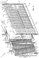
- modules 23 and 33 alternate with one another along a direction Z and are elongated along a direction Y orthogonal to direction Z.
- each module 23 The oil flows inside each module 23 along a respective U-shaped path P formed by a pair of deliver and return sections Q and R both parallel to direction Y ( Figure 5 ).
- Each path P further comprises a section S interposed between sections Q and R.
- each module 23 comprises an inlet section 24 fluidically connected to inlet 21 and an outlet section 25 fluidically connected to outlet 22.
- Each module 23 comprises:
- walls 29 are opposite to each other and orthogonal to direction Z.
- the separator 28 is also parallel to walls 26.
- Each module 23 further comprises a plurality of fins 15 elongated along direction Z and extending between walls 29.
- the separator 28, walls 29 and the portion of wall 26 delimiting section 24 of each module 23 delimit the delivery branch Q of the path P of the oil inside the module 23.
- the separator 28, walls 29 and the portion of wall 26 delimiting section 25 of each module 23 delimit the return branch R of the path P of the oil inside the module 23.
- the fins 15 are arranged with lower density in section S with respect to branches Q and R, in order not to obstruct the curved path of the oil inside the associated module 23.
- the inlet 31 and the outlet 32 of circuit 30 are opposite to each other along direction X.
- each module 33 comprises:
- Each module 33 defines a plurality of cells 45 placed side by side along direction Y and having an extension mainly along direction X.
- Each cell 45 is delimited by:
- Each cell 45 also comprises:
- the inlets 39 and outlets 40 of each cell 45 are fluidically connected to the inlet 31 and the outlet 32, respectively, of circuit 30.
- Module 33 also comprises a plurality of fins 55 interposed between walls 36 and adapted to aid heat exchange between the air that flows in each module 33 and the oil that flows in modules 23 immediately adjacent to modules 33.
- Each cell 45 comprises a row 61 of fins 55, which lie on respective planes orthogonal to direction X; the fins 55 of the row 61 extend at a progressively increasing distances from wall 36a along direction Y, when proceeding along direction X from the respective inlet 39 towards the respective outlets 40.
- Each cell 45 also comprises a row 62 of further fins 55, which extend at progressively increasing distances from wall 36b along direction Y, when proceeding along direction X from the respective inlet 39 towards the respective outlets 40.
- the rows 61 and 62 of fins 55 of each cell 45 converge towards one another when proceeding from the respective inlet 39 towards the respective outlets 40, parallel to direction X.
- Each cell 45 defines:
- the fins 55 of each cell 45 have a thickness along direction X and a length along direction Y.
- mutually consecutive fins 55 of each cell 45 are spaced out along direction X by respective air passages 56.
- the passages 56 place chamber 52 and chambers 53 in fluidic communication.
- Each passage 56 extends along direction Y, is open at its opposite end with reference to direction Y, and is closed along directions X and Z.
- the sum of the areas of the sections orthogonal to direction Y of the passages 56 is greater than the area of the inlet 39 of each cell 45.
- each outlet 40 is less than the area of the associated inlet 39.
- each cell 45 in section orthogonal to direction X is rhomboidal.
- each cell 45 form between them an acute angle ⁇ of less than 45 degrees ( Figure 2 ).
- the heat exchanger 10 is made in a single piece.
- the heat exchanger 10 is made of aluminium.
- the heat exchanger 10 is made using an additive manufacturing technology.
- the printing direction of the heat exchanger 10 is parallel to direction Y.
- the heat exchanger 10 performs heat exchange between an air current and the lubricating oil, enabling the latter to cool.
- the oil enters the heat exchanger 10 through inlet 21, follows circuit 20 inside modules 23 and exits the heat exchanger 10 through outlet 22.
- the air laps the fins 55 of the rows 61 and 62 of each module 33.
- These fins 55 extend from the associated wall 29 and are therefore heated by the oil that flows in the modules 23 adjacent to each module 33.
- heat is given up by the oil in each module 23 to fins 15 and to wall 29, from the latter to fins 55, and from fins 55 to the air that flows in modules 33 adjacent to the aforementioned module 23.
- the still cold air flows inside each module 33, first inside the chamber 52 along section U of the associated path T with a main velocity component substantially parallel to direction X.
- the air is diverted and flows in the passages 56 between fins 55 along section V of the associated path T with a main velocity component substantially parallel to direction Y.
- the heated air then flows from sections 51 to outlet 32.
- the fins 55 of rows 61 and 62 lie on respective planes orthogonal to direction X and extend at progressively increasing distances from the respective walls 36a and 36b along direction Y, when proceeding along direction X from the associated inlet 39 to the associated outlets 40.
- the sum of the areas of the sections orthogonal to direction Y of the passages 56 is greater than the areas of the inlet 39 of each cell 45.
- the air undergoes not only a diversion, but also a slowing down when it laps fins 55.
- the cells 45 do not have undercuts, making the heat exchanger 10 adapted for manufacturing in a single piece using the technology known as additive manufacturing. This technology is particularly flexible regarding the possibility of making fins 55 of different shapes.
- each cell 45 could comprise just one of the rows 61 and 62 of fins 55.
- the module 33 could be formed by a single cell 45 instead of a plurality of cells 45.
- the transmission unit 3 could be one of transmission units 6.
- the heat exchanger 10 could be applied to types of aircraft other than the helicopter 1, for example, a convertiplane or an aeroplane.
Landscapes
- Engineering & Computer Science (AREA)
- Mechanical Engineering (AREA)
- General Engineering & Computer Science (AREA)
- Chemical & Material Sciences (AREA)
- Combustion & Propulsion (AREA)
- Physics & Mathematics (AREA)
- Thermal Sciences (AREA)
- Aviation & Aerospace Engineering (AREA)
- Heat-Exchange Devices With Radiators And Conduit Assemblies (AREA)
- General Details Of Gearings (AREA)
Claims (13)
- Échangeur de chaleur (10) pour une unité de transmission d'un aéronef (1) comprenant :un premier module (23) définissant une première trajectoire d'alimentation (P) pour un premier fluide à refroidir ;un second module (33) définissant une seconde trajectoire d'alimentation (T) pour un second fluide de refroidissement ; lesdites première et seconde trajectoires d'alimentation (P, T) étant, à l'usage, thermiquement couplées entre elles ; chaque dit second module (33) comprenant au moins une cellule (45) formée par :une entrée (39) pour un second fluide de refroidissement ;au moins une sortie (40) pour ledit second fluide de refroidissement, qui est agencée sur le côté opposé à ladite entrée (39) le long d'une première direction (X) ;au moins une première paroi (35) thermiquement couplée à ladite première trajectoire (P) ;une paire de secondes parois (36a, 36b) transversales par rapport à ladite première paroi (35) ;une pluralité d'ailettes (55) faisant saillie, en porte-à-faux, à partir de ladite première paroi (35) et adaptées pour augmenter, à l'usage, l'échange de chaleur entre ledit second fluide de refroidissement et ladite première paroi (35) ; etau moins une première rangée (61) desdites ailettes (55) qui sont sur un plan orthogonal par rapport à ladite première direction (X) ; lesdites ailettes (55) de ladite première rangée (62) s'étendant à des distances progressivement croissantes de l'une (36a) desdites secondes parois (36a, 36b) le long d'une seconde direction (Y) orthogonale par rapport à ladite première direction (X), lorsque l'on continue le long de ladite première direction (X) de ladite entrée (39) à ladite au moins une sortie (40) ;au moins une seconde rangée (62) desdites ailettes (55) ; lesdites ailettes (55) de ladite seconde rangée (62) s'étendant à des distances progressivement croissantes de l'autre (36b) desdites secondes parois (36a, 36b) le long de ladite seconde direction (Y),caractérisé en ce que ladite cellule (45) comprend au moins deux desdites sorties (40) ; lesdites première et seconde rangées (61, 62) délimitant entre elles, une première chambre (52) délimitée par ladite entrée (39) ; l'une (36a) desdites secondes parois (36a, 36b) et ladite première rangée (61) définissant une deuxième chambre (53) délimitée par l'une desdites sorties (40) ; l'autre (36b) desdites secondes parois (36a, 36b) et ladite seconde rangée (62) définissant une troisième chambre (53) délimitée par l'autre desdites sorties (40) ; ladite première chambre et ladite deuxième chambre (52, 53) étant en communication fluidique entre elles via lesdits premiers passages (56) définis entre les premières ailettes (55) mutuellement consécutives respectives de ladite première rangée (61) ; ladite première chambre et ladite troisième chambre (52, 53) étant en communication fluidique entre elles via lesdits seconds passages (56) définis entre les premières ailettes (55) mutuellement consécutives respectives de ladite seconde rangée (62).
- Échangeur de chaleur selon la revendication 1, caractérisé en ce que lesdites ailettes (55) sont espacées le long de ladite première direction (X) et forment une pluralité de passages (56) s'étendant le long de ladite seconde direction (Y).
- Échangeur de chaleur selon la revendication 1 ou 2, caractérisé en ce que lesdites ailettes (55) mutuellement consécutives de ladite première rangée (61) le long de ladite première direction (X) se chevauchent partiellement le long de ladite seconde direction (Y).
- Échangeur de chaleur selon la revendication 2 ou 3, caractérisé en ce que la somme de la surface des sections desdits passages (56) orthogonaux par rapport à ladite seconde direction (Y) est supérieure à la surface de ladite entrée (39).
- Échangeur de chaleur selon la revendication 5, caractérisé en ce que lesdites première et seconde rangées (61, 62) de ladite cellule (45) sont mutuellement convergentes, lorsque l'on continue de ladite entrée (39) vers lesdites sorties (40).
- Échangeur de chaleur selon l'une quelconque des revendications précédentes, caractérisé en ce que ledit second module (33) comprend une pluralité desdites cellules (45) placées côte à côte le long de ladite seconde direction (Y).
- Échangeur de chaleur selon l'une quelconque des revendications précédentes, caractérisé en ce que ladite cellule (45) a un périmètre rhomboïde en coupe orthogonale par rapport à ladite première direction (X).
- Échangeur de chaleur selon la revendication 8, caractérisé en ce que ladite première paroi (35) et l'une desdites secondes parois (36a, 36b) forment un angle aigu (α) inférieur à 45 degrés.
- Échangeur de chaleur selon l'une quelconque des revendications précédentes, caractérisé en ce qu'il est réalisé d'un seul tenant.
- Échangeur de chaleur selon l'une quelconque des revendications précédentes, caractérisé en ce qu'il est réalisé en utilisant une technologie de fabrication additive.
- Échangeur de chaleur selon l'une quelconque des revendications précédentes, caractérisé en ce que ledit premier fluide est un liquide, en particulier de l'huile, et ledit second fluide est un gaz, en particulier de l'air.
- Hélicoptère (1) comprenant :une unité de puissance ;un rotor ;une unité de transmission (3) opérationnellement intercalée entre ladite unité de puissance et ledit rotor ;un circuit de lubrification de ladite unité de transmission (3) ; etun échangeur de chaleur (10) selon l'une quelconque des revendications précédentes et raccordé audit circuit de lubrification.
- Procédé pour refroidir un premier fluide à refroidir au moyen d'échange de chaleur avec un second fluide de refroidissement pour un aéronef (1) comprenant les étapes suivantes :i) amener ledit premier fluide à refroidir le long d'une première trajectoire (P) ;ii) amener ledit second fluide de refroidissement le long d'une seconde trajectoire (T) thermiquement couplée à ladite première trajectoire (P) ;ladite seconde trajectoire (T) comprenant au moins une entrée (39) et au moins une sortie (40) agencée au niveau des extrémités opposées l'une de l'autre le long d'une première direction (X) et étant délimitées par au moins une paroi (35) thermiquement couplée à ladite première trajectoire (P) et par une paire de secondes parois (36a, 36b) transversales à ladite première paroi (35) ;
ladite étape ii) comprenant les étapes suivantes :iii) amener ledit second fluide de refroidissement par ladite entrée (39) avec un composant principal de mouvement parallèle à ladite première direction (X) ;iv) faire dépasser une pluralité d'ailettes (55) en saillie en porte-à-faux de ladite première paroi (35) avec ledit second fluide de refroidissement ;v) amener ledit second fluide de refroidissement par ladite sortie (40) avec un composant principal de mouvement parallèle à ladite première direction (X) ;caractérisé en ce qu'il comprend les étapes suivantes :vi) amener ledit second fluide de refroidissement le long d'une seconde direction (Y) orthogonale à ladite première direction (X) et à travers une pluralité de passages (56) définis entre lesdites ailettes (55) mutuellement consécutives d'une première rangée (61) et des ailettes (55) mutuellement consécutives d'une seconde rangée (62) ; etvii) ralentir ledit second fluide pendant ladite étape vi) et à la fin de ladite étape iii) ;lesdites ailettes (55) de ladite première rangée (61) s'étendant à des distances progressivement croissantes de l'une (36a) desdites secondes parois (36a, 36b) le long d'une seconde direction (Y) orthogonale à ladite première direction (X), lorsque l'on continue le long de ladite première direction (X) de ladite entrée (39) à ladite sortie (40) ;
lesdites ailettes (55) de ladite seconde rangée (62) s'étendant à des distances progressivement croissantes de l'autre (36b) desdites secondes parois (36a, 36b) le long de ladite seconde direction (Y), ladite cellule (45) comprend au moins deux desdites sorties (40) ; lesdites première et seconde rangées (61, 62) délimitant entre elles une première chambre (52) délimitée par ladite entrée (39) ; l'une (36a) desdites secondes parois (36a, 36b) et ladite première rangée (61) définissant une deuxième chambre (53) délimitée par l'une desdites sorties (40) ; l'autre (36b) desdites secondes parois (36a, 36b) et ladite seconde rangée (62) définissant une troisième chambre (53) délimitée par l'autre desdites sorties (40) ; ladite première chambre et ladite deuxième chambre (52, 53) étant en communication fluidique entre elles via lesdits premiers passages (56) définis entre des premières ailettes (55) mutuellement consécutives respectives de ladite première rangée (61) ; ladite première chambre et ladite troisième chambre (52, 53) étant en communication fluidique entre elles via lesdits seconds passages (56) définis entre les premières ailettes (55) mutuellement consécutives respectives de ladite seconde rangée (62).
Priority Applications (5)
| Application Number | Priority Date | Filing Date | Title |
|---|---|---|---|
| EP18187435.5A EP3608617B1 (fr) | 2018-08-06 | 2018-08-06 | Échangeur de chaleur pour aéronef |
| US17/264,180 US11851171B2 (en) | 2018-08-06 | 2019-07-26 | Heat exchanger for an aircraft |
| KR1020217005911A KR20210044234A (ko) | 2018-08-06 | 2019-07-26 | 항공기용 열교환기 |
| CN201980052457.8A CN112566846A (zh) | 2018-08-06 | 2019-07-26 | 用于飞行器的热交换器 |
| PCT/IB2019/056411 WO2020031013A1 (fr) | 2018-08-06 | 2019-07-26 | Échangeur de chaleur pour un aéronef |
Applications Claiming Priority (1)
| Application Number | Priority Date | Filing Date | Title |
|---|---|---|---|
| EP18187435.5A EP3608617B1 (fr) | 2018-08-06 | 2018-08-06 | Échangeur de chaleur pour aéronef |
Publications (2)
| Publication Number | Publication Date |
|---|---|
| EP3608617A1 EP3608617A1 (fr) | 2020-02-12 |
| EP3608617B1 true EP3608617B1 (fr) | 2020-12-16 |
Family
ID=63722133
Family Applications (1)
| Application Number | Title | Priority Date | Filing Date |
|---|---|---|---|
| EP18187435.5A Active EP3608617B1 (fr) | 2018-08-06 | 2018-08-06 | Échangeur de chaleur pour aéronef |
Country Status (5)
| Country | Link |
|---|---|
| US (1) | US11851171B2 (fr) |
| EP (1) | EP3608617B1 (fr) |
| KR (1) | KR20210044234A (fr) |
| CN (1) | CN112566846A (fr) |
| WO (1) | WO2020031013A1 (fr) |
Families Citing this family (3)
| Publication number | Priority date | Publication date | Assignee | Title |
|---|---|---|---|---|
| US11639828B2 (en) * | 2020-06-25 | 2023-05-02 | Turbine Aeronautics IP Pty Ltd | Heat exchanger |
| GB202019056D0 (en) * | 2020-12-03 | 2021-01-20 | Bae Systems Plc | Heat exchanger |
| EP4209348A1 (fr) * | 2022-01-08 | 2023-07-12 | Hamilton Sundstrand Corporation | Échangeur de chaleur à feuilles de séparation ondulées |
Family Cites Families (23)
| Publication number | Priority date | Publication date | Assignee | Title |
|---|---|---|---|---|
| GB1071682A (en) * | 1964-04-10 | 1967-06-14 | Head Wrightson & Co Ltd | Improvements relating to heat exchangers |
| JPS6141896Y2 (fr) | 1981-04-08 | 1986-11-28 | ||
| DE3300929A1 (de) * | 1983-01-13 | 1984-07-19 | Ulf Dipl.-Ing. Dr. 3404 Adelebsen Bossel | Waermetauscher fuer ein kondensierendes oder verdampfendes medium und ein medium ohne phasenuebergang |
| JPS6141896A (ja) * | 1984-08-01 | 1986-02-28 | Mitsubishi Electric Corp | 対向流型熱交換器 |
| DE10102640A1 (de) * | 2001-01-20 | 2002-07-25 | Bayerische Motoren Werke Ag | Wärmetauscher |
| CN100368755C (zh) * | 2002-10-11 | 2008-02-13 | 昭和电工株式会社 | 流体从中流过的扁平空心体部、包含该空心体部的热交换器以及制造该热交换器的方法 |
| WO2004033978A1 (fr) * | 2002-10-11 | 2004-04-22 | Showa Denko K.K. | Corps plat et creux destine au passage d'un fluide, echangeur de chaleur comprenant ce corps creux et procede de fabrication de l'echangeur de chaleur |
| US7871578B2 (en) * | 2005-05-02 | 2011-01-18 | United Technologies Corporation | Micro heat exchanger with thermally conductive porous network |
| FR2905673B1 (fr) * | 2006-09-08 | 2008-11-14 | Eurocopter France | Systeme de climatisation de giravion. |
| JP2009002239A (ja) * | 2007-06-21 | 2009-01-08 | T Rad Co Ltd | Egrクーラ |
| US20090145581A1 (en) * | 2007-12-11 | 2009-06-11 | Paul Hoffman | Non-linear fin heat sink |
| US20150027662A1 (en) * | 2011-08-16 | 2015-01-29 | Antonius Henricus Hubertus Schmitz | Climate system |
| GB2496692B (en) * | 2011-11-21 | 2016-06-08 | Hamilton Sundstrand Corp | Gas turbine engine heat exchanger fins with periodic gaps |
| US9161478B2 (en) * | 2012-02-24 | 2015-10-13 | Futurewei Technologies, Inc. | Apparatus and method for an active antenna heat sink |
| FR2988822B1 (fr) | 2012-03-28 | 2014-04-04 | Eurocopter France | Echangeur thermique a plaques a ondulations sinusoidales pour turbomoteur |
| CN103547115A (zh) * | 2012-07-13 | 2014-01-29 | 台达电子工业股份有限公司 | 散热器、电子装置与热交换装置 |
| US9599410B2 (en) * | 2012-07-27 | 2017-03-21 | General Electric Company | Plate-like air-cooled engine surface cooler with fluid channel and varying fin geometry |
| EP2712805B1 (fr) * | 2012-09-28 | 2016-03-02 | AGUSTAWESTLAND S.p.A. | Système et procédé de refroidissement d'une transmission d'aéronef capable d'effectuer du vol stationnaire |
| DE102012223644A1 (de) * | 2012-12-18 | 2014-06-18 | Behr Gmbh & Co. Kg | Wärmetauscher |
| JP2016531032A (ja) | 2013-06-03 | 2016-10-06 | ユニゾン・インダストリーズ,エルエルシー | 航空機用共形表面熱交換器 |
| WO2016018498A1 (fr) | 2014-07-31 | 2016-02-04 | Sikorsky Aircraft Corporation | Ensemble de refroidissement d'huile de boîte de vitesses |
| US9638471B2 (en) * | 2014-11-10 | 2017-05-02 | Hamilton Sundstrand Corporation | Balanced heat exchanger systems and methods |
| TWM528417U (zh) * | 2016-02-19 | 2016-09-11 | Enzotechnology Corp | 利用散熱體排列達低風壓需求、低噪音、高效能之散熱器 |
-
2018
- 2018-08-06 EP EP18187435.5A patent/EP3608617B1/fr active Active
-
2019
- 2019-07-26 US US17/264,180 patent/US11851171B2/en active Active
- 2019-07-26 CN CN201980052457.8A patent/CN112566846A/zh active Pending
- 2019-07-26 KR KR1020217005911A patent/KR20210044234A/ko not_active Application Discontinuation
- 2019-07-26 WO PCT/IB2019/056411 patent/WO2020031013A1/fr active Application Filing
Non-Patent Citations (1)
| Title |
|---|
| None * |
Also Published As
| Publication number | Publication date |
|---|---|
| KR20210044234A (ko) | 2021-04-22 |
| CN112566846A (zh) | 2021-03-26 |
| US11851171B2 (en) | 2023-12-26 |
| US20210163124A1 (en) | 2021-06-03 |
| EP3608617A1 (fr) | 2020-02-12 |
| WO2020031013A1 (fr) | 2020-02-13 |
Similar Documents
| Publication | Publication Date | Title |
|---|---|---|
| US11851171B2 (en) | Heat exchanger for an aircraft | |
| US8647053B2 (en) | Cooling arrangement for a turbine component | |
| CA2806068C (fr) | Refroidisseur d'huile refroidi a l'air pour un moteur a turbine | |
| WO2015071933A1 (fr) | Échangeur de chaleur d'aéronef | |
| EP3117169A1 (fr) | Échangeur thermique | |
| CN105783338B (zh) | 热交换器 | |
| SE454211B (sv) | Vermevexlare med en tredje stromningsbana for forvermning av kall fluid | |
| US20190153947A1 (en) | Turbine engine nacelle comprising a cooling device | |
| US20220153085A1 (en) | Temperature control device, in particular cooling device for a motor vehicle | |
| US11414202B2 (en) | Plate cooler for aircraft electronic components | |
| EP3196584B1 (fr) | Échangeur de chaleur ayant des entrées et des sorties adjacentes | |
| CN109538327B (zh) | 油冷却器 | |
| EP3271674B1 (fr) | Système de refroidissement | |
| EP3196581B1 (fr) | Échangeur de chaleur ayant un collecteur central et séparateur thermique | |
| JP2015014429A (ja) | 積層型熱交換器 | |
| CN107036334B (zh) | 改进的热交换器 | |
| EP3855107A1 (fr) | Échangeur de chaleur fractal | |
| US20220011049A1 (en) | Heat exchanger and system for cooling a fluid comprising such a heat exchanger | |
| EP2724107B1 (fr) | Échangeur de chaleur à enveloppe et à tubes avec microcanaux | |
| EP2716889B1 (fr) | Refroidissement redondant pour systèmes refroidis par fluides | |
| EP3137836B1 (fr) | Échangeur de chaleur amélioré | |
| RU2780085C2 (ru) | Теплообменник для летательного аппарата | |
| JP2012145311A (ja) | 車両用空調装置 | |
| US20220196347A1 (en) | Temperature control device, in particular a cooling device for a motor vehicle | |
| US9976645B2 (en) | System and method of transferring heat between transmission fluid and coolant in oil pan |
Legal Events
| Date | Code | Title | Description |
|---|---|---|---|
| PUAI | Public reference made under article 153(3) epc to a published international application that has entered the european phase |
Free format text: ORIGINAL CODE: 0009012 |
|
| STAA | Information on the status of an ep patent application or granted ep patent |
Free format text: STATUS: REQUEST FOR EXAMINATION WAS MADE |
|
| 17P | Request for examination filed |
Effective date: 20190424 |
|
| AK | Designated contracting states |
Kind code of ref document: A1 Designated state(s): AL AT BE BG CH CY CZ DE DK EE ES FI FR GB GR HR HU IE IS IT LI LT LU LV MC MK MT NL NO PL PT RO RS SE SI SK SM TR |
|
| AX | Request for extension of the european patent |
Extension state: BA ME |
|
| GRAP | Despatch of communication of intention to grant a patent |
Free format text: ORIGINAL CODE: EPIDOSNIGR1 |
|
| STAA | Information on the status of an ep patent application or granted ep patent |
Free format text: STATUS: GRANT OF PATENT IS INTENDED |
|
| INTG | Intention to grant announced |
Effective date: 20200709 |
|
| GRAS | Grant fee paid |
Free format text: ORIGINAL CODE: EPIDOSNIGR3 |
|
| GRAA | (expected) grant |
Free format text: ORIGINAL CODE: 0009210 |
|
| STAA | Information on the status of an ep patent application or granted ep patent |
Free format text: STATUS: THE PATENT HAS BEEN GRANTED |
|
| AK | Designated contracting states |
Kind code of ref document: B1 Designated state(s): AL AT BE BG CH CY CZ DE DK EE ES FI FR GB GR HR HU IE IS IT LI LT LU LV MC MK MT NL NO PL PT RO RS SE SI SK SM TR |
|
| REG | Reference to a national code |
Ref country code: GB Ref legal event code: FG4D |
|
| REG | Reference to a national code |
Ref country code: IE Ref legal event code: FG4D |
|
| REG | Reference to a national code |
Ref country code: DE Ref legal event code: R096 Ref document number: 602018010795 Country of ref document: DE |
|
| REG | Reference to a national code |
Ref country code: AT Ref legal event code: REF Ref document number: 1345973 Country of ref document: AT Kind code of ref document: T Effective date: 20210115 |
|
| PG25 | Lapsed in a contracting state [announced via postgrant information from national office to epo] |
Ref country code: RS Free format text: LAPSE BECAUSE OF FAILURE TO SUBMIT A TRANSLATION OF THE DESCRIPTION OR TO PAY THE FEE WITHIN THE PRESCRIBED TIME-LIMIT Effective date: 20201216 Ref country code: FI Free format text: LAPSE BECAUSE OF FAILURE TO SUBMIT A TRANSLATION OF THE DESCRIPTION OR TO PAY THE FEE WITHIN THE PRESCRIBED TIME-LIMIT Effective date: 20201216 Ref country code: GR Free format text: LAPSE BECAUSE OF FAILURE TO SUBMIT A TRANSLATION OF THE DESCRIPTION OR TO PAY THE FEE WITHIN THE PRESCRIBED TIME-LIMIT Effective date: 20210317 Ref country code: NO Free format text: LAPSE BECAUSE OF FAILURE TO SUBMIT A TRANSLATION OF THE DESCRIPTION OR TO PAY THE FEE WITHIN THE PRESCRIBED TIME-LIMIT Effective date: 20210316 |
|
| REG | Reference to a national code |
Ref country code: AT Ref legal event code: MK05 Ref document number: 1345973 Country of ref document: AT Kind code of ref document: T Effective date: 20201216 |
|
| REG | Reference to a national code |
Ref country code: NL Ref legal event code: MP Effective date: 20201216 |
|
| PG25 | Lapsed in a contracting state [announced via postgrant information from national office to epo] |
Ref country code: SE Free format text: LAPSE BECAUSE OF FAILURE TO SUBMIT A TRANSLATION OF THE DESCRIPTION OR TO PAY THE FEE WITHIN THE PRESCRIBED TIME-LIMIT Effective date: 20201216 Ref country code: LV Free format text: LAPSE BECAUSE OF FAILURE TO SUBMIT A TRANSLATION OF THE DESCRIPTION OR TO PAY THE FEE WITHIN THE PRESCRIBED TIME-LIMIT Effective date: 20201216 Ref country code: BG Free format text: LAPSE BECAUSE OF FAILURE TO SUBMIT A TRANSLATION OF THE DESCRIPTION OR TO PAY THE FEE WITHIN THE PRESCRIBED TIME-LIMIT Effective date: 20210316 |
|
| PG25 | Lapsed in a contracting state [announced via postgrant information from national office to epo] |
Ref country code: NL Free format text: LAPSE BECAUSE OF FAILURE TO SUBMIT A TRANSLATION OF THE DESCRIPTION OR TO PAY THE FEE WITHIN THE PRESCRIBED TIME-LIMIT Effective date: 20201216 Ref country code: HR Free format text: LAPSE BECAUSE OF FAILURE TO SUBMIT A TRANSLATION OF THE DESCRIPTION OR TO PAY THE FEE WITHIN THE PRESCRIBED TIME-LIMIT Effective date: 20201216 |
|
| REG | Reference to a national code |
Ref country code: LT Ref legal event code: MG9D |
|
| PG25 | Lapsed in a contracting state [announced via postgrant information from national office to epo] |
Ref country code: SM Free format text: LAPSE BECAUSE OF FAILURE TO SUBMIT A TRANSLATION OF THE DESCRIPTION OR TO PAY THE FEE WITHIN THE PRESCRIBED TIME-LIMIT Effective date: 20201216 Ref country code: CZ Free format text: LAPSE BECAUSE OF FAILURE TO SUBMIT A TRANSLATION OF THE DESCRIPTION OR TO PAY THE FEE WITHIN THE PRESCRIBED TIME-LIMIT Effective date: 20201216 Ref country code: EE Free format text: LAPSE BECAUSE OF FAILURE TO SUBMIT A TRANSLATION OF THE DESCRIPTION OR TO PAY THE FEE WITHIN THE PRESCRIBED TIME-LIMIT Effective date: 20201216 Ref country code: LT Free format text: LAPSE BECAUSE OF FAILURE TO SUBMIT A TRANSLATION OF THE DESCRIPTION OR TO PAY THE FEE WITHIN THE PRESCRIBED TIME-LIMIT Effective date: 20201216 Ref country code: RO Free format text: LAPSE BECAUSE OF FAILURE TO SUBMIT A TRANSLATION OF THE DESCRIPTION OR TO PAY THE FEE WITHIN THE PRESCRIBED TIME-LIMIT Effective date: 20201216 Ref country code: SK Free format text: LAPSE BECAUSE OF FAILURE TO SUBMIT A TRANSLATION OF THE DESCRIPTION OR TO PAY THE FEE WITHIN THE PRESCRIBED TIME-LIMIT Effective date: 20201216 Ref country code: PT Free format text: LAPSE BECAUSE OF FAILURE TO SUBMIT A TRANSLATION OF THE DESCRIPTION OR TO PAY THE FEE WITHIN THE PRESCRIBED TIME-LIMIT Effective date: 20210416 |
|
| PG25 | Lapsed in a contracting state [announced via postgrant information from national office to epo] |
Ref country code: AT Free format text: LAPSE BECAUSE OF FAILURE TO SUBMIT A TRANSLATION OF THE DESCRIPTION OR TO PAY THE FEE WITHIN THE PRESCRIBED TIME-LIMIT Effective date: 20201216 Ref country code: PL Free format text: LAPSE BECAUSE OF FAILURE TO SUBMIT A TRANSLATION OF THE DESCRIPTION OR TO PAY THE FEE WITHIN THE PRESCRIBED TIME-LIMIT Effective date: 20201216 |
|
| REG | Reference to a national code |
Ref country code: DE Ref legal event code: R097 Ref document number: 602018010795 Country of ref document: DE |
|
| PG25 | Lapsed in a contracting state [announced via postgrant information from national office to epo] |
Ref country code: IS Free format text: LAPSE BECAUSE OF FAILURE TO SUBMIT A TRANSLATION OF THE DESCRIPTION OR TO PAY THE FEE WITHIN THE PRESCRIBED TIME-LIMIT Effective date: 20210416 |
|
| PLBE | No opposition filed within time limit |
Free format text: ORIGINAL CODE: 0009261 |
|
| STAA | Information on the status of an ep patent application or granted ep patent |
Free format text: STATUS: NO OPPOSITION FILED WITHIN TIME LIMIT |
|
| PG25 | Lapsed in a contracting state [announced via postgrant information from national office to epo] |
Ref country code: AL Free format text: LAPSE BECAUSE OF FAILURE TO SUBMIT A TRANSLATION OF THE DESCRIPTION OR TO PAY THE FEE WITHIN THE PRESCRIBED TIME-LIMIT Effective date: 20201216 |
|
| 26N | No opposition filed |
Effective date: 20210917 |
|
| PG25 | Lapsed in a contracting state [announced via postgrant information from national office to epo] |
Ref country code: DK Free format text: LAPSE BECAUSE OF FAILURE TO SUBMIT A TRANSLATION OF THE DESCRIPTION OR TO PAY THE FEE WITHIN THE PRESCRIBED TIME-LIMIT Effective date: 20201216 |
|
| PG25 | Lapsed in a contracting state [announced via postgrant information from national office to epo] |
Ref country code: ES Free format text: LAPSE BECAUSE OF FAILURE TO SUBMIT A TRANSLATION OF THE DESCRIPTION OR TO PAY THE FEE WITHIN THE PRESCRIBED TIME-LIMIT Effective date: 20201216 |
|
| PG25 | Lapsed in a contracting state [announced via postgrant information from national office to epo] |
Ref country code: SI Free format text: LAPSE BECAUSE OF FAILURE TO SUBMIT A TRANSLATION OF THE DESCRIPTION OR TO PAY THE FEE WITHIN THE PRESCRIBED TIME-LIMIT Effective date: 20201216 |
|
| REG | Reference to a national code |
Ref country code: CH Ref legal event code: PL |
|
| PG25 | Lapsed in a contracting state [announced via postgrant information from national office to epo] |
Ref country code: MC Free format text: LAPSE BECAUSE OF FAILURE TO SUBMIT A TRANSLATION OF THE DESCRIPTION OR TO PAY THE FEE WITHIN THE PRESCRIBED TIME-LIMIT Effective date: 20201216 |
|
| REG | Reference to a national code |
Ref country code: BE Ref legal event code: MM Effective date: 20210831 |
|
| PG25 | Lapsed in a contracting state [announced via postgrant information from national office to epo] |
Ref country code: LI Free format text: LAPSE BECAUSE OF NON-PAYMENT OF DUE FEES Effective date: 20210831 Ref country code: CH Free format text: LAPSE BECAUSE OF NON-PAYMENT OF DUE FEES Effective date: 20210831 |
|
| PG25 | Lapsed in a contracting state [announced via postgrant information from national office to epo] |
Ref country code: IS Free format text: LAPSE BECAUSE OF FAILURE TO SUBMIT A TRANSLATION OF THE DESCRIPTION OR TO PAY THE FEE WITHIN THE PRESCRIBED TIME-LIMIT Effective date: 20210416 Ref country code: LU Free format text: LAPSE BECAUSE OF NON-PAYMENT OF DUE FEES Effective date: 20210806 |
|
| PG25 | Lapsed in a contracting state [announced via postgrant information from national office to epo] |
Ref country code: IE Free format text: LAPSE BECAUSE OF NON-PAYMENT OF DUE FEES Effective date: 20210806 Ref country code: BE Free format text: LAPSE BECAUSE OF NON-PAYMENT OF DUE FEES Effective date: 20210831 |
|
| PG25 | Lapsed in a contracting state [announced via postgrant information from national office to epo] |
Ref country code: CY Free format text: LAPSE BECAUSE OF FAILURE TO SUBMIT A TRANSLATION OF THE DESCRIPTION OR TO PAY THE FEE WITHIN THE PRESCRIBED TIME-LIMIT Effective date: 20201216 |
|
| PG25 | Lapsed in a contracting state [announced via postgrant information from national office to epo] |
Ref country code: HU Free format text: LAPSE BECAUSE OF FAILURE TO SUBMIT A TRANSLATION OF THE DESCRIPTION OR TO PAY THE FEE WITHIN THE PRESCRIBED TIME-LIMIT; INVALID AB INITIO Effective date: 20180806 |
|
| PGFP | Annual fee paid to national office [announced via postgrant information from national office to epo] |
Ref country code: IT Payment date: 20230719 Year of fee payment: 6 Ref country code: GB Payment date: 20230822 Year of fee payment: 6 |
|
| P01 | Opt-out of the competence of the unified patent court (upc) registered |
Effective date: 20231005 |
|
| PGFP | Annual fee paid to national office [announced via postgrant information from national office to epo] |
Ref country code: FR Payment date: 20230824 Year of fee payment: 6 Ref country code: DE Payment date: 20230828 Year of fee payment: 6 |
|
| PG25 | Lapsed in a contracting state [announced via postgrant information from national office to epo] |
Ref country code: MK Free format text: LAPSE BECAUSE OF FAILURE TO SUBMIT A TRANSLATION OF THE DESCRIPTION OR TO PAY THE FEE WITHIN THE PRESCRIBED TIME-LIMIT Effective date: 20201216 |