EP3608569B1 - Durchflussregelventil mit wirbelstromdämpfung - Google Patents
Durchflussregelventil mit wirbelstromdämpfung Download PDFInfo
- Publication number
- EP3608569B1 EP3608569B1 EP19171916.0A EP19171916A EP3608569B1 EP 3608569 B1 EP3608569 B1 EP 3608569B1 EP 19171916 A EP19171916 A EP 19171916A EP 3608569 B1 EP3608569 B1 EP 3608569B1
- Authority
- EP
- European Patent Office
- Prior art keywords
- shuttle
- flow
- magnet
- fixed
- valve
- Prior art date
- Legal status (The legal status is an assumption and is not a legal conclusion. Google has not performed a legal analysis and makes no representation as to the accuracy of the status listed.)
- Active
Links
Images


Classifications
-
- F—MECHANICAL ENGINEERING; LIGHTING; HEATING; WEAPONS; BLASTING
- F16—ENGINEERING ELEMENTS AND UNITS; GENERAL MEASURES FOR PRODUCING AND MAINTAINING EFFECTIVE FUNCTIONING OF MACHINES OR INSTALLATIONS; THERMAL INSULATION IN GENERAL
- F16K—VALVES; TAPS; COCKS; ACTUATING-FLOATS; DEVICES FOR VENTING OR AERATING
- F16K31/00—Actuating devices; Operating means; Releasing devices
- F16K31/02—Actuating devices; Operating means; Releasing devices electric; magnetic
- F16K31/06—Actuating devices; Operating means; Releasing devices electric; magnetic using a magnet, e.g. diaphragm valves, cutting off by means of a liquid
- F16K31/0644—One-way valve
- F16K31/0651—One-way valve the fluid passing through the solenoid coil
-
- F—MECHANICAL ENGINEERING; LIGHTING; HEATING; WEAPONS; BLASTING
- F16—ENGINEERING ELEMENTS AND UNITS; GENERAL MEASURES FOR PRODUCING AND MAINTAINING EFFECTIVE FUNCTIONING OF MACHINES OR INSTALLATIONS; THERMAL INSULATION IN GENERAL
- F16K—VALVES; TAPS; COCKS; ACTUATING-FLOATS; DEVICES FOR VENTING OR AERATING
- F16K1/00—Lift valves or globe valves, i.e. cut-off apparatus with closure members having at least a component of their opening and closing motion perpendicular to the closing faces
- F16K1/32—Details
-
- F—MECHANICAL ENGINEERING; LIGHTING; HEATING; WEAPONS; BLASTING
- F16—ENGINEERING ELEMENTS AND UNITS; GENERAL MEASURES FOR PRODUCING AND MAINTAINING EFFECTIVE FUNCTIONING OF MACHINES OR INSTALLATIONS; THERMAL INSULATION IN GENERAL
- F16K—VALVES; TAPS; COCKS; ACTUATING-FLOATS; DEVICES FOR VENTING OR AERATING
- F16K1/00—Lift valves or globe valves, i.e. cut-off apparatus with closure members having at least a component of their opening and closing motion perpendicular to the closing faces
- F16K1/12—Lift valves or globe valves, i.e. cut-off apparatus with closure members having at least a component of their opening and closing motion perpendicular to the closing faces with streamlined valve member around which the fluid flows when the valve is opened
- F16K1/123—Lift valves or globe valves, i.e. cut-off apparatus with closure members having at least a component of their opening and closing motion perpendicular to the closing faces with streamlined valve member around which the fluid flows when the valve is opened with stationary valve member and moving sleeve
-
- F—MECHANICAL ENGINEERING; LIGHTING; HEATING; WEAPONS; BLASTING
- F16—ENGINEERING ELEMENTS AND UNITS; GENERAL MEASURES FOR PRODUCING AND MAINTAINING EFFECTIVE FUNCTIONING OF MACHINES OR INSTALLATIONS; THERMAL INSULATION IN GENERAL
- F16K—VALVES; TAPS; COCKS; ACTUATING-FLOATS; DEVICES FOR VENTING OR AERATING
- F16K27/00—Construction of housing; Use of materials therefor
- F16K27/02—Construction of housing; Use of materials therefor of lift valves
- F16K27/029—Electromagnetically actuated valves
-
- F—MECHANICAL ENGINEERING; LIGHTING; HEATING; WEAPONS; BLASTING
- F16—ENGINEERING ELEMENTS AND UNITS; GENERAL MEASURES FOR PRODUCING AND MAINTAINING EFFECTIVE FUNCTIONING OF MACHINES OR INSTALLATIONS; THERMAL INSULATION IN GENERAL
- F16K—VALVES; TAPS; COCKS; ACTUATING-FLOATS; DEVICES FOR VENTING OR AERATING
- F16K27/00—Construction of housing; Use of materials therefor
- F16K27/04—Construction of housing; Use of materials therefor of sliding valves
- F16K27/048—Electromagnetically actuated valves
-
- F—MECHANICAL ENGINEERING; LIGHTING; HEATING; WEAPONS; BLASTING
- F16—ENGINEERING ELEMENTS AND UNITS; GENERAL MEASURES FOR PRODUCING AND MAINTAINING EFFECTIVE FUNCTIONING OF MACHINES OR INSTALLATIONS; THERMAL INSULATION IN GENERAL
- F16K—VALVES; TAPS; COCKS; ACTUATING-FLOATS; DEVICES FOR VENTING OR AERATING
- F16K3/00—Gate valves or sliding valves, i.e. cut-off apparatus with closing members having a sliding movement along the seat for opening and closing
- F16K3/22—Gate valves or sliding valves, i.e. cut-off apparatus with closing members having a sliding movement along the seat for opening and closing with sealing faces shaped as surfaces of solids of revolution
- F16K3/24—Gate valves or sliding valves, i.e. cut-off apparatus with closing members having a sliding movement along the seat for opening and closing with sealing faces shaped as surfaces of solids of revolution with cylindrical valve members
- F16K3/246—Combination of a sliding valve and a lift valve
-
- F—MECHANICAL ENGINEERING; LIGHTING; HEATING; WEAPONS; BLASTING
- F16—ENGINEERING ELEMENTS AND UNITS; GENERAL MEASURES FOR PRODUCING AND MAINTAINING EFFECTIVE FUNCTIONING OF MACHINES OR INSTALLATIONS; THERMAL INSULATION IN GENERAL
- F16K—VALVES; TAPS; COCKS; ACTUATING-FLOATS; DEVICES FOR VENTING OR AERATING
- F16K3/00—Gate valves or sliding valves, i.e. cut-off apparatus with closing members having a sliding movement along the seat for opening and closing
- F16K3/22—Gate valves or sliding valves, i.e. cut-off apparatus with closing members having a sliding movement along the seat for opening and closing with sealing faces shaped as surfaces of solids of revolution
- F16K3/24—Gate valves or sliding valves, i.e. cut-off apparatus with closing members having a sliding movement along the seat for opening and closing with sealing faces shaped as surfaces of solids of revolution with cylindrical valve members
- F16K3/26—Gate valves or sliding valves, i.e. cut-off apparatus with closing members having a sliding movement along the seat for opening and closing with sealing faces shaped as surfaces of solids of revolution with cylindrical valve members with fluid passages in the valve member
- F16K3/265—Gate valves or sliding valves, i.e. cut-off apparatus with closing members having a sliding movement along the seat for opening and closing with sealing faces shaped as surfaces of solids of revolution with cylindrical valve members with fluid passages in the valve member with a sleeve sliding in the direction of the flow line
-
- F—MECHANICAL ENGINEERING; LIGHTING; HEATING; WEAPONS; BLASTING
- F16—ENGINEERING ELEMENTS AND UNITS; GENERAL MEASURES FOR PRODUCING AND MAINTAINING EFFECTIVE FUNCTIONING OF MACHINES OR INSTALLATIONS; THERMAL INSULATION IN GENERAL
- F16K—VALVES; TAPS; COCKS; ACTUATING-FLOATS; DEVICES FOR VENTING OR AERATING
- F16K3/00—Gate valves or sliding valves, i.e. cut-off apparatus with closing members having a sliding movement along the seat for opening and closing
- F16K3/22—Gate valves or sliding valves, i.e. cut-off apparatus with closing members having a sliding movement along the seat for opening and closing with sealing faces shaped as surfaces of solids of revolution
- F16K3/24—Gate valves or sliding valves, i.e. cut-off apparatus with closing members having a sliding movement along the seat for opening and closing with sealing faces shaped as surfaces of solids of revolution with cylindrical valve members
- F16K3/26—Gate valves or sliding valves, i.e. cut-off apparatus with closing members having a sliding movement along the seat for opening and closing with sealing faces shaped as surfaces of solids of revolution with cylindrical valve members with fluid passages in the valve member
- F16K3/267—Combination of a sliding valve and a lift valve
-
- F—MECHANICAL ENGINEERING; LIGHTING; HEATING; WEAPONS; BLASTING
- F16—ENGINEERING ELEMENTS AND UNITS; GENERAL MEASURES FOR PRODUCING AND MAINTAINING EFFECTIVE FUNCTIONING OF MACHINES OR INSTALLATIONS; THERMAL INSULATION IN GENERAL
- F16K—VALVES; TAPS; COCKS; ACTUATING-FLOATS; DEVICES FOR VENTING OR AERATING
- F16K31/00—Actuating devices; Operating means; Releasing devices
- F16K31/02—Actuating devices; Operating means; Releasing devices electric; magnetic
- F16K31/06—Actuating devices; Operating means; Releasing devices electric; magnetic using a magnet, e.g. diaphragm valves, cutting off by means of a liquid
- F16K31/0644—One-way valve
- F16K31/0655—Lift valves
-
- F—MECHANICAL ENGINEERING; LIGHTING; HEATING; WEAPONS; BLASTING
- F16—ENGINEERING ELEMENTS AND UNITS; GENERAL MEASURES FOR PRODUCING AND MAINTAINING EFFECTIVE FUNCTIONING OF MACHINES OR INSTALLATIONS; THERMAL INSULATION IN GENERAL
- F16K—VALVES; TAPS; COCKS; ACTUATING-FLOATS; DEVICES FOR VENTING OR AERATING
- F16K31/00—Actuating devices; Operating means; Releasing devices
- F16K31/02—Actuating devices; Operating means; Releasing devices electric; magnetic
- F16K31/06—Actuating devices; Operating means; Releasing devices electric; magnetic using a magnet, e.g. diaphragm valves, cutting off by means of a liquid
- F16K31/0644—One-way valve
- F16K31/0668—Sliding valves
-
- F—MECHANICAL ENGINEERING; LIGHTING; HEATING; WEAPONS; BLASTING
- F16—ENGINEERING ELEMENTS AND UNITS; GENERAL MEASURES FOR PRODUCING AND MAINTAINING EFFECTIVE FUNCTIONING OF MACHINES OR INSTALLATIONS; THERMAL INSULATION IN GENERAL
- F16K—VALVES; TAPS; COCKS; ACTUATING-FLOATS; DEVICES FOR VENTING OR AERATING
- F16K31/00—Actuating devices; Operating means; Releasing devices
- F16K31/02—Actuating devices; Operating means; Releasing devices electric; magnetic
- F16K31/06—Actuating devices; Operating means; Releasing devices electric; magnetic using a magnet, e.g. diaphragm valves, cutting off by means of a liquid
- F16K31/0675—Electromagnet aspects, e.g. electric supply therefor
-
- F—MECHANICAL ENGINEERING; LIGHTING; HEATING; WEAPONS; BLASTING
- F16—ENGINEERING ELEMENTS AND UNITS; GENERAL MEASURES FOR PRODUCING AND MAINTAINING EFFECTIVE FUNCTIONING OF MACHINES OR INSTALLATIONS; THERMAL INSULATION IN GENERAL
- F16K—VALVES; TAPS; COCKS; ACTUATING-FLOATS; DEVICES FOR VENTING OR AERATING
- F16K31/00—Actuating devices; Operating means; Releasing devices
- F16K31/02—Actuating devices; Operating means; Releasing devices electric; magnetic
- F16K31/06—Actuating devices; Operating means; Releasing devices electric; magnetic using a magnet, e.g. diaphragm valves, cutting off by means of a liquid
- F16K31/08—Actuating devices; Operating means; Releasing devices electric; magnetic using a magnet, e.g. diaphragm valves, cutting off by means of a liquid using a permanent magnet
- F16K31/082—Actuating devices; Operating means; Releasing devices electric; magnetic using a magnet, e.g. diaphragm valves, cutting off by means of a liquid using a permanent magnet using a electromagnet and a permanent magnet
-
- F—MECHANICAL ENGINEERING; LIGHTING; HEATING; WEAPONS; BLASTING
- F16—ENGINEERING ELEMENTS AND UNITS; GENERAL MEASURES FOR PRODUCING AND MAINTAINING EFFECTIVE FUNCTIONING OF MACHINES OR INSTALLATIONS; THERMAL INSULATION IN GENERAL
- F16K—VALVES; TAPS; COCKS; ACTUATING-FLOATS; DEVICES FOR VENTING OR AERATING
- F16K31/00—Actuating devices; Operating means; Releasing devices
- F16K31/02—Actuating devices; Operating means; Releasing devices electric; magnetic
- F16K31/06—Actuating devices; Operating means; Releasing devices electric; magnetic using a magnet, e.g. diaphragm valves, cutting off by means of a liquid
- F16K31/08—Actuating devices; Operating means; Releasing devices electric; magnetic using a magnet, e.g. diaphragm valves, cutting off by means of a liquid using a permanent magnet
- F16K31/086—Actuating devices; Operating means; Releasing devices electric; magnetic using a magnet, e.g. diaphragm valves, cutting off by means of a liquid using a permanent magnet the magnet being movable and actuating a second magnet connected to the closing element
-
- F—MECHANICAL ENGINEERING; LIGHTING; HEATING; WEAPONS; BLASTING
- F16—ENGINEERING ELEMENTS AND UNITS; GENERAL MEASURES FOR PRODUCING AND MAINTAINING EFFECTIVE FUNCTIONING OF MACHINES OR INSTALLATIONS; THERMAL INSULATION IN GENERAL
- F16K—VALVES; TAPS; COCKS; ACTUATING-FLOATS; DEVICES FOR VENTING OR AERATING
- F16K31/00—Actuating devices; Operating means; Releasing devices
- F16K31/02—Actuating devices; Operating means; Releasing devices electric; magnetic
- F16K31/06—Actuating devices; Operating means; Releasing devices electric; magnetic using a magnet, e.g. diaphragm valves, cutting off by means of a liquid
- F16K31/10—Actuating devices; Operating means; Releasing devices electric; magnetic using a magnet, e.g. diaphragm valves, cutting off by means of a liquid with additional mechanism between armature and closure member
-
- F—MECHANICAL ENGINEERING; LIGHTING; HEATING; WEAPONS; BLASTING
- F16—ENGINEERING ELEMENTS AND UNITS; GENERAL MEASURES FOR PRODUCING AND MAINTAINING EFFECTIVE FUNCTIONING OF MACHINES OR INSTALLATIONS; THERMAL INSULATION IN GENERAL
- F16K—VALVES; TAPS; COCKS; ACTUATING-FLOATS; DEVICES FOR VENTING OR AERATING
- F16K37/00—Special means in or on valves or other cut-off apparatus for indicating or recording operation thereof, or for enabling an alarm to be given
- F16K37/0025—Electrical or magnetic means
- F16K37/005—Electrical or magnetic means for measuring fluid parameters
-
- F—MECHANICAL ENGINEERING; LIGHTING; HEATING; WEAPONS; BLASTING
- F16—ENGINEERING ELEMENTS AND UNITS; GENERAL MEASURES FOR PRODUCING AND MAINTAINING EFFECTIVE FUNCTIONING OF MACHINES OR INSTALLATIONS; THERMAL INSULATION IN GENERAL
- F16K—VALVES; TAPS; COCKS; ACTUATING-FLOATS; DEVICES FOR VENTING OR AERATING
- F16K37/00—Special means in or on valves or other cut-off apparatus for indicating or recording operation thereof, or for enabling an alarm to be given
- F16K37/0075—For recording or indicating the functioning of a valve in combination with test equipment
- F16K37/0091—For recording or indicating the functioning of a valve in combination with test equipment by measuring fluid parameters
-
- F—MECHANICAL ENGINEERING; LIGHTING; HEATING; WEAPONS; BLASTING
- F16—ENGINEERING ELEMENTS AND UNITS; GENERAL MEASURES FOR PRODUCING AND MAINTAINING EFFECTIVE FUNCTIONING OF MACHINES OR INSTALLATIONS; THERMAL INSULATION IN GENERAL
- F16K—VALVES; TAPS; COCKS; ACTUATING-FLOATS; DEVICES FOR VENTING OR AERATING
- F16K47/00—Means in valves for absorbing fluid energy
-
- B—PERFORMING OPERATIONS; TRANSPORTING
- B24—GRINDING; POLISHING
- B24C—ABRASIVE OR RELATED BLASTING WITH PARTICULATE MATERIAL
- B24C7/00—Equipment for feeding abrasive material; Controlling the flowability, constitution, or other physical characteristics of abrasive blasts
-
- Y—GENERAL TAGGING OF NEW TECHNOLOGICAL DEVELOPMENTS; GENERAL TAGGING OF CROSS-SECTIONAL TECHNOLOGIES SPANNING OVER SEVERAL SECTIONS OF THE IPC; TECHNICAL SUBJECTS COVERED BY FORMER USPC CROSS-REFERENCE ART COLLECTIONS [XRACs] AND DIGESTS
- Y10—TECHNICAL SUBJECTS COVERED BY FORMER USPC
- Y10T—TECHNICAL SUBJECTS COVERED BY FORMER US CLASSIFICATION
- Y10T137/00—Fluid handling
- Y10T137/3367—Larner-Johnson type valves; i.e., telescoping internal valve in expanded flow line section
Definitions
- This present disclosure relates to flow control valves that control the flow of particulate, such as is used in media blasting, shot peening, or other systems where the user desires to control the flow of different types of flowable particulate and sense the amount passing through the valve.
- Existing flowable particulate valves in the art suffer from complexity, manufacturability, and functionality issues. Most valves use a fixed orifice and a movable pintle that retracts to allow media to flow. The pintle is spring-loaded to bias it towards the closed position, creating issues for assembly and maintenance. The spring can wear, break, or become damaged, creating functionality issues. When actuated, the pintle can bounce, creating control problems. Another problem is having closed loop control of the valve by knowing exactly the amount of media that is being dispensed. Other designs use a deflected beam as a means to measure, while others use optical or other sensing technology. An improved valve with media sensing is needed.
- US5351934A discloses a permanent magnet, proportional solenoid valve having a suspended armature which is separated from two opposing pole pieces by two normally unequal gaps having a collectively constant dimension.
- the magnetic field originating from the magnet extends through the gaps and is used to bias the armature to a position at which the valve is normally closed.
- the present disclosure describes a valve designed to regulate the flow of a particulate media.
- the valve has an inlet portion that funnels the particulate media down through the center of the valve.
- the inlet portion has repelling magnets and a shield.
- the shield reduces the magnetic field from the magnet that passes through the center of the valve.
- the inlet portion has a shuttle sleeve that carries the particulate media on the inside. Surrounding the outside of the shuttle sleeve is a movable shuttle.
- the shuttle has shuttle magnets and a magnetic shield that reduces the magnetic field from the magnets that passes through the center of the valve.
- the shuttle has a movable orifice attached to it that contacts a flow director.
- the flow director is located in the outlet portion and channels the media past a flow sensor to detect the amount of particulate being dispensed.
- a portion of the valve is made from a metal, such as brass or copper, that interacts with the shuttle magnets to generate eddy currents when the shuttle is in motion. The eddy currents act to dampen the movement of the shuttle.
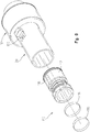
- FIGS. 1-8 An electrically operated valve 10 is shown in FIGS. 1-8 with an inlet 12 and an outlet 14.
- the valve 10 is designed to regulate the flow of particulate media that is not ferro-magnetic.
- the particulate media is flowable, commonly a blasting media such as glass, plastic, aluminum oxide, or other particulate. In other words, particulate media made from steel or alloys of Iron are not commonly used with the valve 10.
- the particulate media is loaded into the inlet 12, commonly from a hopper or other storage vessel (not shown).
- the valve 10 is operable between an opened state and a closed state. The opened state allows particulate media to flow from the inlet 12 to the outlet 14, while the closed state blocks the particulate media from flowing.
- the valve 10 can operate in positions between the open and closed positions in order to regulate the flow of particulate media.
- the valve 10 has a tube 20 that is shown as a hollow cylindrical tube with a consistent wall thickness, but other structures are contemplated, such as a square, rectangular, or other elongate hollow component that allows a flow path.
- the inlet 12 is located near a top edge 22 and the outlet 14 is located near a bottom edge 24.
- the tube 20 may be threaded at its ends or have a feature to allow it to attach to other containers, tubes, or devices.
- the valve 10 has a central axis 16 that is located at the center of the tube 20.
- the tube 20 has an inside surface 26 where other components contact or seal against.
- the tube 20 in the embodiment described herein is formed from copper or a copper alloy, such as brass or bronze.
- the tube 20 may also be made from aluminum or other material that is electrically conductive or responds to a changing magnetic field.
- a coil 32 surrounds the tube 20 that is also fixed with respect to the tube 20.
- the coil 32 has windings 34 that generate a magnetic field when energized.
- the valve 10 may include a housing (not shown) that surrounds a portion of the tube 20 and includes controls, wiring, and circuit boards.
- a funnel 40 is located adjacent the top edge 22 and is shown as centered about the central axis 16.
- a seal 42 seals the funnel 40 to the inside surface 26 of the tube 20.
- the funnel 40 has a wide open mouth with an inside surface 44 that narrows down to a cylindrical surface 46.
- the inside surface 44 is conical in nature but the device is not limited to that shape. It is contemplated that the inside surface 44 of the funnel 40 is straight and any funnel or conical feature is externally located above the valve 10.
- the funnel 40 may also be considered as an inlet portion.
- the funnel 40 is axially located in the tube 20 by a step surface 45 and includes set screws 41 that impinge against the tube 20 and prevent movement of the funnel 40 with respect to the tube 20.
- the funnel 40 includes repelling magnets 48 that are equally spaced around the cylindrical surface 46.
- the repelling magnets 48 are pressed into place or otherwise secured with adhesive or fasteners that prevents the magnets 48 from falling out or becoming loose.
- the funnel 40 is made from a non-magnetic material, such as plastic, aluminum, ceramic, or other material that does not short out or conduct the magnetic field from the repelling magnets 48.
- the inside surface 44 and cylindrical surface 46 cooperate to direct particulate to the inside of a shuttle sleeve 50.
- the shuttle sleeve 50 is a cylindrical tubular component, made from a non-magnetic material such as plastic or aluminum, with an inside surface 52 and outside surface 54.
- the shuttle sleeve 50 is secured to the funnel 40 through a press fit, threading, or other attachment method that affixes the two components.
- the shuttle sleeve 50 is centered about the central axis 16 and has a terminal edge 56 that is opposite the open mouth.
- a skirt surface 58 that is closely matched to the inside surface 26 of the tube 20 extends down from the open mouth to the top of the shuttle sleeve 50.
- Adjacent the repelling magnets 48 is a funnel shield 60 that conducts magnetic field from the repelling magnets 48 to keep the magnetic field away from the inside flow path of the funnel 40.
- the funnel shield 60 shunts the field to the point that ferrous or magnetic particles do not accumulate.
- a shuttle 70 is located around the shuttle sleeve 50 and also centered about the central axis 16.
- the shuttle 70 is hollow and slidable along the outside surface 54 of the shuttle sleeve 50 between an open position (shown in FIG. 4 ) and a closed position (shown in FIG. 3 ).
- the shuttle 70 has shuttle magnets 72 that are contained in a shuttle body 74.
- the shuttle body 74 is made from a non-ferromagnetic material, such as plastic, aluminum, ceramic, or other material that does not short out or conduct the magnetic field of the shuttle magnets 72, and includes a shuttle magnet shield 76 that is located adjacent the shuttle magnets 72 and closer to the central axis 16.
- the shuttle magnet shield 76 shunts the magnetic field generated by the shuttle magnets 72 that could attract ferrous particles or other particles. The particles may be attracted to a magnetic field and build up on the shuttle sleeve 50 or the shuttle 70, or get stuck between the shuttle body 74 and shuttle sleeve 50.
- Extending from the lower portion of the shuttle body 74 and affixed thereto is a movable orifice 78.
- the movable orifice 78 is a tubular component with a terminal sealing edge 80, shown in FIG. 4 .
- the movable orifice 78 is made from metal (such as aluminum), but other materials are contemplated.
- the movable orifice 78 includes a tapered surface 82 located on the inside that extends from the inside surface 84.
- the media flows from the shuttle sleeve 50 and into the inside of the movable orifice 78.
- the tapered surface 82 may include other features designed to modify the flow properties of the particulate media, such as channels, different angles, or additional surfaces.
- a fixed flow director 90 is affixed to the tube 20 near the bottom edge 24 and is also centered about the central axis 16.
- the flow director 90 has a removable cone portion 92 with a replaceable seal 93 having a sealing surface 94.
- the terminal edge 56 of the shuttle sleeve 50 is spaced above the sealing surface 94 and the two are a fixed distance apart.
- the replaceable seal 93 is made from steel, but other materials are contemplated.
- the sealing surface 94 is groove-shaped to receive and locate the terminal sealing edge 80 on the shuttle 70. It is held between the cone portion 92 and the flow directing portion 100, which may be press fit or threaded.
- the cone portion 92 is tapered with a top and conical surface 96, 98.
- the cone portion 92 may be parabolic, curved, or straight, depending on the properties of the particulate media that may be used.
- the flow directing portion 100 has an outer diameter surface 102.
- a mounting base 104 locates the fixed flow director 90 to be aligned with the central axis 16 and allows flow through it via arcuate apertures 106.
- the cone portion 92 and sealing surface 94 is designed to mate with the movable orifice 78 and the terminal sealing edge 80 to open or close a flow path between the funnel 40 and flow directing portion 100.
- the fixed flow director 90 is separable from the base 104 to allow different cone portion 92 and flow directing portions 100 to be exchanged for different desired flow properties of the particulate media.
- the flow director 90 may have a different shape than the flow director 90 shown in FIG. 3 .
- the purpose of the flow director 90 is to direct media outwardly from a central region of the tube 20 and toward the inside surface 26 of the tube 20. For instance, it is not necessary that the flow director 90 have a cone portion 92.
- the flow directing portion 100 of the flow director 90 will prevent media from being located in the central region of tube 20, which corresponds to areas of the tube 26 that adjacent to the central axis 16 of the tube 26.
- the distance the shuttle 70 moves away from the cone portion 92 creates a variable gap for the particulate media to pass through. Increasing the amount of energy applied to the coil 32 increases the amount that the shuttle 70 moves away from the closed position.
- a flow sensor 110 surrounds the fixed flow director 90 that detects the amount of particulate media that is passing between the outer diameter surface 102 and flow sensor 110.
- the flow sensor 110 is shown as located and attached to a flow sensor body 112.
- the flow sensor body 112 is located between the mounting base 104 and a step 107 in the tube 20.
- the flow sensor body 112 is sealed to the tube 20 with seals 108, 109.
- the sensor 110 is capacitive and includes sensor rings 114, 116 that sense movement of the particulate media adjacent the sensor rings 114, 116.
- the sensor rings 114, 116 are near the inside surface 26 of the tube 20. Wires connect the sensor rings 114, 116 to an external circuit through a channel 118 in the sensor body 112 and out through the wire egress 120.
- the external circuit is commonly located inside the housing (not shown) and can be used by the valve 10 for closed loop control of the shuttle 70.
- the flow sensor 110 and sensor body 112 are secured to the tube 20 using fasteners, adhesive, or other method.
- the mounting base 104 is secured through fasteners 122. Removing the fasteners 122 allows the mounting base 104, flow directing portion 100, cone portion 92, and replaceable seal 93 to be removed for maintenance, cleaning, or component exchange for a different media.
- the flow sensor 110 is shown as using sensor rings 114, 116 that are adjacent the flow path for the particulate media, but it is contemplated that other sensor designs are used.
- the flow director 90 directs media relatively near the sensor rings and away from the central axis 16 of the tube 20, where the media would be relatively far from the sensor rings. If sensor configurations not using capacitive elements such as rings 114, 116 are employed, it is desirable for the media to be located near the capacitive elements and the flow diverter 90 serves that purpose.
- a sensor could be the use of one sensor ring is located in the flow sensor body 112, and the other ring is located in the flow directing portion 100.
- the flow director 90 may be made from a material that conducts and connects to the external circuit 118 to form part of the sensor 110.
- the repelling magnets 48 in the funnel 40 have a north-south orientation that puts the magnetic field as it exits the magnet parallel to the central axis 16. Some of the field is conducted through the funnel shield 60.
- the shuttle magnets 72 are aligned in a similar fashion such that the magnetic field as it exits the magnet is parallel to the central axis 16, with some of the field conducted through the shuttle magnet shield 76.
- the shuttle magnets 72 and repelling magnets 48 have identical facing poles and generate an increasing repelling force as they are brought closer to each other. For example, if the shuttle magnets 72 have a north pole that faces the repelling magnets 48, the repelling magnets would be oriented to have a north pole that faces the shuttle magnets 72.
- the repelling force generated by the magnets 48, 72 acts like a spring that biases the shuttle 70 away from the funnel 40. Because of the biased force from the magnets 48, 72, no spring is required. Ordinarily, a valve would require a spring to ensure the shuttle returns to the closed position when the electric current is removed.
- the tube 20 may be made from copper, aluminum, or a copper alloy, and the shuttle 70 has an array of shuttle magnets 72. Because the shuttle magnets 72 are in close proximity to the tube 20, any movement of the shuttle 70 creates eddy currents in the tube 20. Eddy currents are created when a magnet is moved with respect to a conductive metal, such as brass, copper, or aluminum.
- the tube 20 in the embodiment herein is described as brass but other materials are contemplated.
- the valve 10 takes advantage of the eddy currents and uses them to act as a dampening force on the shuttle 70.
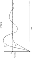
- the shuttle 70 would react in an underdamped fashion 73, where it would first overshoot its desired position 71 and then oscillate until it settles down to its desired position 71. In other words, the shuttle 70 would bounce back and forth before arriving at its desired position 71, represented in FIG. 9 . Because the position of the shuttle 70 directly determines the amount of particulate media dispensed, overshoot and oscillation of the shuttle 70 would cause the particulate media to be dispensed unevenly, particularly when the valve 10 is first actuated or when the shuttle 70 is otherwise moved by the coil 32. Because of the eddy currents generated by the movement of the shuttle 70, overshoot and oscillation of the shuttle 70 are reduced or eliminated and the shuttle 70 responds in a damped fashion 75.
- the valve 10 is separated into several general chambers where the particulate can be present or flow through, shown in FIGS. 5A and 5B .
- the valve 10 is designed to be attached in a vertical orientation, with axis 16 being aligned with the force of gravity and have a supply of media present in the inlet chamber 130.
- the inlet chamber 130 starts at the top edge 22 of the tube 20 and is generally comprised of the internal volume inside of the funnel 40 and shuttle sleeve 50.
- the outlet and sensor chamber 132 is defined by the internal volume starting at the sealing surface 94, extending between the outer diameter surface 102 and inner diameter surface 113 of the sensor body 112, and terminating at the arcuate apertures 106.
- the outlet and sensor chamber 132 will only contain particulate while it is flowing through the valve 10, while the inlet chamber 130 will contain media regardless of flow.
- a center chamber 134 Located between the inlet chamber 130 and outlet and sensor chamber 132 is a center chamber 134 that is defined by the internal volume between the terminal edge 56 and terminal sealing edge 80.
- the internal volumes herein described are the areas inside the valve 10 that can hold and dispense media. The internal volumes make up the flow path through the valve 10.
- the media contacts the inside surfaces 82, 84 of the shuttle sleeve 78.
- the center chamber 134 like the inlet chamber 130, may have media regardless of flow. Media that is released when the shuttle 70 moves and separates the terminal sealing edge 80 from the sealing surface 94 passes through the outlet and sensor chamber 132 substantially unimpeded.
- the media As the media passes through the portion of the outlet and sensor chamber 132 that is surrounded by the flow sensor 110, the media is detected by the flow sensor 110. Because the outlet and sensor chamber 132 is encircled by the sensor rings 114, 116 at an equal distance, the media is reliably detected. Detection is further enhanced by having the flow diverter 90 predictably locate the media in a flow path very near the sensor rings 114, 116.
Landscapes
- Engineering & Computer Science (AREA)
- General Engineering & Computer Science (AREA)
- Mechanical Engineering (AREA)
- Physics & Mathematics (AREA)
- Electromagnetism (AREA)
- Fluid Mechanics (AREA)
- Magnetically Actuated Valves (AREA)
- Electrically Driven Valve-Operating Means (AREA)
Claims (6)
- Elektrisch betriebenes Durchflussventil (10) für Partikel, wobei das Durchflussventil Folgendes umfasst:einen Einlassabschnitt (40) mit einer Einlasskammer (130), wobei ein abstoßender Magnet (48) in Bezug auf die Einlasskammer fixiert ist, wobei sich die Einlasskammer von einem Einlass zu einer Endkante (56) an einer Shuttle-Hülse (50) erstreckt;eine Dichtungsfläche (94), die in Bezug auf die Endkante an der Shuttle-Hülse fixiert ist;ein Shuttle (70), welches die Shuttle-Hülse begrenzt und in Bezug auf die Shuttle-Hülse zwischen einer geöffneten Position und einer geschlossenen Position verschiebbar ist, wobei die geöffnete Position dadurch definiert ist, dass eine Dichtungskante (80) des Shuttles von der Dichtungsfläche beabstandet ist und ein Shuttle-Magnet (72) sich näher an dem abstoßenden Magneten befindet, wobei die geschlossene Position durch die Dichtungskante des Shuttles definiert ist, welche die Dichtungsfläche berührt, und der Shuttle-Magnet sich weiter weg von dem abstoßenden Magneten befindet, wobei der Einlassabschnitt einen trichterförmigen Schirm (60) aufweist, der sich benachbart zu dem abstoßenden Magneten befindet, und das Shuttle einen Shuttle-Magnetenschirm (76) aufweist, der sich benachbart zu dem Shuttle-Magneten befindet, wobei der abstoßende Magnet den Shuttle-Magneten abstößt, um das Shuttle zu der geschlossenen Position vorzuspannen;einen Auslassabschnitt mit einer Auslasskammer, die sich von der Dichtungsfläche zu einem Auslass (14) erstreckt, wobei ein Durchflussleiter (90) in Bezug auf die Shuttle-Hülse fixiert ist, um die Partikel von einer zentralen Region des Auslassabschnitts weg zu leiten, wobei der Auslassabschnitt einen kapazitiven Sensor (110) beinhaltet, wobei sich der kapazitive Sensor in einem Durchflusssensorkörper (112) befindet, der eine Fläche aufweist, die dem fixierten Durchflussleiter zugewandt ist, wobei die Fläche mit dem fixierten Durchflussleiter zusammenwirkt, um einen ringförmigen Durchflussweg zu definieren; undein Rohr (20), welches den Shuttle-Magneten umgibt, wobei das Rohr in Bezug auf die Shuttle-Hülse fixiert ist und das Rohr aus einem Material besteht, welches Wirbelströme erzeugt, wenn sich der Shuttle zwischen der geöffneten und der geschlossenen Position verschiebt.
- Durchflussventil nach Anspruch 1, wobei der fixierte Durchflussleiter zylindrisch ist.
- Durchflussventil nach Anspruch 1, wobei der kapazitive Sensor einen ersten Sensorring (114) aufweist, der sich benachbart zu einem zweiten Sensorring (116) befindet.
- Durchflussventil nach Anspruch 1, wobei die Dichtungsfläche (94) sich auf dem fixierten Durchflussleiter (90) befindet und eine ringförmige Nut ist.
- Durchflussventil nach Anspruch 1, wobei der fixierte Durchflussleiter einen Konusabschnitt aufweist, wobei sich der Konusabschnitt in einer zentralen Kammer befindet, wobei sich die zentrale Kammer zwischen der Einlasskammer und der Auslasskammer befindet.
- Durchflussventil nach Anspruch 1, wobei die Einlasskammer einen Trichter aufweist, der einen größeren Durchmesser in der Nähe einer oberen Kante aufweist und sich in Richtung der Shuttle-Hülse zu einem kleineren Durchmesser verengt.
Applications Claiming Priority (1)
| Application Number | Priority Date | Filing Date | Title |
|---|---|---|---|
| US16/055,136 US10253901B1 (en) | 2018-08-05 | 2018-08-05 | Flow control valve with eddy current dampening |
Publications (2)
| Publication Number | Publication Date |
|---|---|
| EP3608569A1 EP3608569A1 (de) | 2020-02-12 |
| EP3608569B1 true EP3608569B1 (de) | 2020-08-26 |
Family
ID=65998058
Family Applications (1)
| Application Number | Title | Priority Date | Filing Date |
|---|---|---|---|
| EP19171916.0A Active EP3608569B1 (de) | 2018-08-05 | 2019-04-30 | Durchflussregelventil mit wirbelstromdämpfung |
Country Status (7)
| Country | Link |
|---|---|
| US (1) | US10253901B1 (de) |
| EP (1) | EP3608569B1 (de) |
| JP (1) | JP6821804B2 (de) |
| CN (1) | CN110805702B (de) |
| CA (1) | CA3041139C (de) |
| SG (1) | SG11201903740SA (de) |
| WO (1) | WO2020032987A1 (de) |
Families Citing this family (8)
| Publication number | Priority date | Publication date | Assignee | Title |
|---|---|---|---|---|
| US10451464B1 (en) * | 2018-08-05 | 2019-10-22 | Electronics Inc. | Capacitive sensor for a flow control valve |
| US10823308B1 (en) * | 2019-06-20 | 2020-11-03 | Hamilton Sunstrand Corporation | Controllers for inline valves, inline valves, and methods of controlling flow through inline valves |
| US10830372B1 (en) * | 2019-06-20 | 2020-11-10 | Hamilton Sunstrand Corporation | Pneumatic controllers, pneumatically controlled inline valves, and methods of cooling pneumatic controllers |
| US10823087B1 (en) * | 2019-06-20 | 2020-11-03 | Hamilton Sunstrand Corporation | Inline valves, gas turbine engines with inline bleed valves, and methods controlling flow through inline valves |
| US10824172B1 (en) * | 2019-06-20 | 2020-11-03 | Hamilton Sunstrand Corporation | Pneumatic controllers, pneumatically controlled inline valves, and methods of actuating inline valves |
| CN112228626A (zh) * | 2020-10-16 | 2021-01-15 | 王威朝 | 一种自感知压缩式高密封性直通闸阀 |
| CN114576417B (zh) * | 2022-04-13 | 2025-07-25 | 三桥惠(佛山)新材料有限公司 | 一种压力电磁阀 |
| WO2025129270A1 (en) * | 2023-12-22 | 2025-06-26 | Blastone Technology Pty Ltd | Nipple for measuring speed of a stream of abrasive particles |
Family Cites Families (17)
| Publication number | Priority date | Publication date | Assignee | Title |
|---|---|---|---|---|
| US1477722A (en) * | 1923-12-18 | slattery | ||
| JPS5747080A (en) * | 1980-09-04 | 1982-03-17 | Taiheiyo Kogyo Kk | Flow control solenoid valve |
| US4770389A (en) * | 1986-05-14 | 1988-09-13 | Chevron Research Company | Electric valve device |
| US5159949A (en) * | 1988-12-23 | 1992-11-03 | Dresser Industries, Inc. | Electropneumatic positioner |
| US5351934A (en) * | 1992-12-15 | 1994-10-04 | Alliedsignal, Inc. | Proportional solenoid valve |
| US5435337A (en) * | 1993-12-15 | 1995-07-25 | Fike Corporation | Inline control valve for controlling fluid flow |
| US5459406A (en) * | 1994-07-01 | 1995-10-17 | Cornell Research Foundation, Inc. | Guarded capacitance probes for measuring particle concentration and flow |
| DE10261610A1 (de) * | 2002-12-27 | 2004-07-08 | Robert Bosch Gmbh | Ventil zum Steuern eines Fluids |
| US20070151614A1 (en) * | 2005-12-29 | 2007-07-05 | Dayton Robert A | Pressure regulating valve |
| DE102008027259A1 (de) * | 2008-06-06 | 2009-12-17 | Focke & Co.(Gmbh & Co. Kg) | Verfahren und Vorrichtung zur Herstellung von Zigarettenpackungen |
| DE102009032521B4 (de) * | 2009-07-10 | 2016-03-31 | Continental Automotive Gmbh | Bestimmung des Schließzeitpunkts eines Kraftstoffeinspritzventils basierend auf einer Auswertung der Ansteuerspannung |
| US8540209B2 (en) * | 2010-09-15 | 2013-09-24 | University of Pittsburgh—of the Commonwealth System of Higher Education | Active combustion flow modulation valve |
| DE102012221616B4 (de) * | 2012-11-27 | 2015-03-12 | Siemens Aktiengesellschaft | Magnetisch induktiver Durchflussmesser |
| EP2881636B1 (de) * | 2013-12-04 | 2016-09-07 | Sidel S.p.a. Con Socio Unico | Ventil mit magnetischem Stellglied |
| CN104132177A (zh) * | 2014-07-23 | 2014-11-05 | 成都气海机电制造有限公司 | 一种微型电磁阀 |
| US9702477B1 (en) * | 2015-12-17 | 2017-07-11 | Glen A. Robertson | Power versatile and energy efficient electric coaxial valve |
| DE102016102252B4 (de) * | 2016-02-10 | 2019-02-07 | VAG GmbH | Regel- oder Absperrarmatur |
-
2018
- 2018-08-05 US US16/055,136 patent/US10253901B1/en active Active
- 2018-10-31 WO PCT/US2018/058419 patent/WO2020032987A1/en not_active Ceased
- 2018-10-31 JP JP2019524461A patent/JP6821804B2/ja active Active
- 2018-10-31 SG SG11201903740SA patent/SG11201903740SA/en unknown
-
2019
- 2019-04-25 CA CA3041139A patent/CA3041139C/en not_active Expired - Fee Related
- 2019-04-30 EP EP19171916.0A patent/EP3608569B1/de active Active
- 2019-05-17 CN CN201910414341.6A patent/CN110805702B/zh active Active
Non-Patent Citations (1)
| Title |
|---|
| None * |
Also Published As
| Publication number | Publication date |
|---|---|
| WO2020032987A1 (en) | 2020-02-13 |
| US10253901B1 (en) | 2019-04-09 |
| CN110805702A (zh) | 2020-02-18 |
| CA3041139A1 (en) | 2019-07-04 |
| CA3041139C (en) | 2019-10-01 |
| JP2020528983A (ja) | 2020-10-01 |
| JP6821804B2 (ja) | 2021-01-27 |
| CN110805702B (zh) | 2020-11-06 |
| SG11201903740SA (en) | 2020-03-30 |
| EP3608569A1 (de) | 2020-02-12 |
Similar Documents
| Publication | Publication Date | Title |
|---|---|---|
| CA3041139C (en) | Flow control valve with eddy current dampening | |
| US10451464B1 (en) | Capacitive sensor for a flow control valve | |
| US3510814A (en) | Solenoid operator having armature provided with guide rings | |
| US4961561A (en) | Solenoid valve | |
| US4569504A (en) | Solenoid | |
| CN101484060B (zh) | 带有过滤器自清洁装置的吸尘器 | |
| CN109555890B (zh) | 隔膜阀 | |
| JPH04254306A (ja) | 磁気装置 | |
| KR970707561A (ko) | 솔레노이드 및 솔레노이드 밸브 | |
| JP6313057B2 (ja) | ショット・ピーニング流量制御部 | |
| CN103534520A (zh) | 可切换限压阀 | |
| US5362027A (en) | Flow regulating valve for magnetic particles | |
| US7246787B2 (en) | Solenoid valve assembly | |
| NL8800166A (nl) | Klep. | |
| KR940015296A (ko) | 자기 유체 펌프 | |
| US2783021A (en) | Electromagnetic air puffer valve unit | |
| US8915481B2 (en) | Magnetically actuable valve | |
| CN110036227B (zh) | 阀装置 | |
| CN109469758B (zh) | 用于控制流体的阀 | |
| CN101258352A (zh) | 具有双稳态电磁控制组件的液流阀 | |
| KR101866472B1 (ko) | 펄스 폭 변조 방식의 분무 조절 구조의 노즐 어셈블리 | |
| US3446472A (en) | Electrically operated fluid flow control devices | |
| US1769268A (en) | Magnetic separator for spouts | |
| JPH07190237A (ja) | ガス用の流量制御装置 | |
| NL8100236A (nl) | Door een mediumstroom bediende schakelinrichting. |
Legal Events
| Date | Code | Title | Description |
|---|---|---|---|
| PUAI | Public reference made under article 153(3) epc to a published international application that has entered the european phase |
Free format text: ORIGINAL CODE: 0009012 |
|
| STAA | Information on the status of an ep patent application or granted ep patent |
Free format text: STATUS: THE APPLICATION HAS BEEN PUBLISHED |
|
| AK | Designated contracting states |
Kind code of ref document: A1 Designated state(s): AL AT BE BG CH CY CZ DE DK EE ES FI FR GB GR HR HU IE IS IT LI LT LU LV MC MK MT NL NO PL PT RO RS SE SI SK SM TR |
|
| AX | Request for extension of the european patent |
Extension state: BA ME |
|
| STAA | Information on the status of an ep patent application or granted ep patent |
Free format text: STATUS: REQUEST FOR EXAMINATION WAS MADE |
|
| 17P | Request for examination filed |
Effective date: 20200331 |
|
| RBV | Designated contracting states (corrected) |
Designated state(s): AL AT BE BG CH CY CZ DE DK EE ES FI FR GB GR HR HU IE IS IT LI LT LU LV MC MK MT NL NO PL PT RO RS SE SI SK SM TR |
|
| RIC1 | Information provided on ipc code assigned before grant |
Ipc: F16K 31/08 20060101AFI20200514BHEP Ipc: F16K 1/12 20060101ALI20200514BHEP Ipc: F16K 37/00 20060101ALI20200514BHEP Ipc: F16K 31/06 20060101ALI20200514BHEP |
|
| GRAP | Despatch of communication of intention to grant a patent |
Free format text: ORIGINAL CODE: EPIDOSNIGR1 |
|
| STAA | Information on the status of an ep patent application or granted ep patent |
Free format text: STATUS: GRANT OF PATENT IS INTENDED |
|
| INTG | Intention to grant announced |
Effective date: 20200619 |
|
| GRAS | Grant fee paid |
Free format text: ORIGINAL CODE: EPIDOSNIGR3 |
|
| GRAA | (expected) grant |
Free format text: ORIGINAL CODE: 0009210 |
|
| STAA | Information on the status of an ep patent application or granted ep patent |
Free format text: STATUS: THE PATENT HAS BEEN GRANTED |
|
| AK | Designated contracting states |
Kind code of ref document: B1 Designated state(s): AL AT BE BG CH CY CZ DE DK EE ES FI FR GB GR HR HU IE IS IT LI LT LU LV MC MK MT NL NO PL PT RO RS SE SI SK SM TR |
|
| REG | Reference to a national code |
Ref country code: GB Ref legal event code: FG4D |
|
| REG | Reference to a national code |
Ref country code: CH Ref legal event code: EP |
|
| REG | Reference to a national code |
Ref country code: AT Ref legal event code: REF Ref document number: 1306703 Country of ref document: AT Kind code of ref document: T Effective date: 20200915 |
|
| REG | Reference to a national code |
Ref country code: IE Ref legal event code: FG4D |
|
| REG | Reference to a national code |
Ref country code: DE Ref legal event code: R096 Ref document number: 602019000547 Country of ref document: DE |
|
| REG | Reference to a national code |
Ref country code: LT Ref legal event code: MG4D |
|
| PG25 | Lapsed in a contracting state [announced via postgrant information from national office to epo] |
Ref country code: GR Free format text: LAPSE BECAUSE OF FAILURE TO SUBMIT A TRANSLATION OF THE DESCRIPTION OR TO PAY THE FEE WITHIN THE PRESCRIBED TIME-LIMIT Effective date: 20201127 Ref country code: NO Free format text: LAPSE BECAUSE OF FAILURE TO SUBMIT A TRANSLATION OF THE DESCRIPTION OR TO PAY THE FEE WITHIN THE PRESCRIBED TIME-LIMIT Effective date: 20201126 Ref country code: BG Free format text: LAPSE BECAUSE OF FAILURE TO SUBMIT A TRANSLATION OF THE DESCRIPTION OR TO PAY THE FEE WITHIN THE PRESCRIBED TIME-LIMIT Effective date: 20201126 Ref country code: HR Free format text: LAPSE BECAUSE OF FAILURE TO SUBMIT A TRANSLATION OF THE DESCRIPTION OR TO PAY THE FEE WITHIN THE PRESCRIBED TIME-LIMIT Effective date: 20200826 Ref country code: SE Free format text: LAPSE BECAUSE OF FAILURE TO SUBMIT A TRANSLATION OF THE DESCRIPTION OR TO PAY THE FEE WITHIN THE PRESCRIBED TIME-LIMIT Effective date: 20200826 Ref country code: PT Free format text: LAPSE BECAUSE OF FAILURE TO SUBMIT A TRANSLATION OF THE DESCRIPTION OR TO PAY THE FEE WITHIN THE PRESCRIBED TIME-LIMIT Effective date: 20201228 Ref country code: FI Free format text: LAPSE BECAUSE OF FAILURE TO SUBMIT A TRANSLATION OF THE DESCRIPTION OR TO PAY THE FEE WITHIN THE PRESCRIBED TIME-LIMIT Effective date: 20200826 Ref country code: LT Free format text: LAPSE BECAUSE OF FAILURE TO SUBMIT A TRANSLATION OF THE DESCRIPTION OR TO PAY THE FEE WITHIN THE PRESCRIBED TIME-LIMIT Effective date: 20200826 |
|
| REG | Reference to a national code |
Ref country code: NL Ref legal event code: MP Effective date: 20200826 |
|
| REG | Reference to a national code |
Ref country code: AT Ref legal event code: MK05 Ref document number: 1306703 Country of ref document: AT Kind code of ref document: T Effective date: 20200826 |
|
| PG25 | Lapsed in a contracting state [announced via postgrant information from national office to epo] |
Ref country code: NL Free format text: LAPSE BECAUSE OF FAILURE TO SUBMIT A TRANSLATION OF THE DESCRIPTION OR TO PAY THE FEE WITHIN THE PRESCRIBED TIME-LIMIT Effective date: 20200826 Ref country code: PL Free format text: LAPSE BECAUSE OF FAILURE TO SUBMIT A TRANSLATION OF THE DESCRIPTION OR TO PAY THE FEE WITHIN THE PRESCRIBED TIME-LIMIT Effective date: 20200826 Ref country code: RS Free format text: LAPSE BECAUSE OF FAILURE TO SUBMIT A TRANSLATION OF THE DESCRIPTION OR TO PAY THE FEE WITHIN THE PRESCRIBED TIME-LIMIT Effective date: 20200826 Ref country code: LV Free format text: LAPSE BECAUSE OF FAILURE TO SUBMIT A TRANSLATION OF THE DESCRIPTION OR TO PAY THE FEE WITHIN THE PRESCRIBED TIME-LIMIT Effective date: 20200826 Ref country code: IS Free format text: LAPSE BECAUSE OF FAILURE TO SUBMIT A TRANSLATION OF THE DESCRIPTION OR TO PAY THE FEE WITHIN THE PRESCRIBED TIME-LIMIT Effective date: 20201226 |
|
| PG25 | Lapsed in a contracting state [announced via postgrant information from national office to epo] |
Ref country code: SM Free format text: LAPSE BECAUSE OF FAILURE TO SUBMIT A TRANSLATION OF THE DESCRIPTION OR TO PAY THE FEE WITHIN THE PRESCRIBED TIME-LIMIT Effective date: 20200826 Ref country code: RO Free format text: LAPSE BECAUSE OF FAILURE TO SUBMIT A TRANSLATION OF THE DESCRIPTION OR TO PAY THE FEE WITHIN THE PRESCRIBED TIME-LIMIT Effective date: 20200826 Ref country code: CZ Free format text: LAPSE BECAUSE OF FAILURE TO SUBMIT A TRANSLATION OF THE DESCRIPTION OR TO PAY THE FEE WITHIN THE PRESCRIBED TIME-LIMIT Effective date: 20200826 Ref country code: DK Free format text: LAPSE BECAUSE OF FAILURE TO SUBMIT A TRANSLATION OF THE DESCRIPTION OR TO PAY THE FEE WITHIN THE PRESCRIBED TIME-LIMIT Effective date: 20200826 Ref country code: EE Free format text: LAPSE BECAUSE OF FAILURE TO SUBMIT A TRANSLATION OF THE DESCRIPTION OR TO PAY THE FEE WITHIN THE PRESCRIBED TIME-LIMIT Effective date: 20200826 |
|
| REG | Reference to a national code |
Ref country code: DE Ref legal event code: R097 Ref document number: 602019000547 Country of ref document: DE |
|
| PG25 | Lapsed in a contracting state [announced via postgrant information from national office to epo] |
Ref country code: AL Free format text: LAPSE BECAUSE OF FAILURE TO SUBMIT A TRANSLATION OF THE DESCRIPTION OR TO PAY THE FEE WITHIN THE PRESCRIBED TIME-LIMIT Effective date: 20200826 Ref country code: AT Free format text: LAPSE BECAUSE OF FAILURE TO SUBMIT A TRANSLATION OF THE DESCRIPTION OR TO PAY THE FEE WITHIN THE PRESCRIBED TIME-LIMIT Effective date: 20200826 Ref country code: ES Free format text: LAPSE BECAUSE OF FAILURE TO SUBMIT A TRANSLATION OF THE DESCRIPTION OR TO PAY THE FEE WITHIN THE PRESCRIBED TIME-LIMIT Effective date: 20200826 |
|
| PG25 | Lapsed in a contracting state [announced via postgrant information from national office to epo] |
Ref country code: SK Free format text: LAPSE BECAUSE OF FAILURE TO SUBMIT A TRANSLATION OF THE DESCRIPTION OR TO PAY THE FEE WITHIN THE PRESCRIBED TIME-LIMIT Effective date: 20200826 |
|
| PLBE | No opposition filed within time limit |
Free format text: ORIGINAL CODE: 0009261 |
|
| STAA | Information on the status of an ep patent application or granted ep patent |
Free format text: STATUS: NO OPPOSITION FILED WITHIN TIME LIMIT |
|
| PG25 | Lapsed in a contracting state [announced via postgrant information from national office to epo] |
Ref country code: IT Free format text: LAPSE BECAUSE OF FAILURE TO SUBMIT A TRANSLATION OF THE DESCRIPTION OR TO PAY THE FEE WITHIN THE PRESCRIBED TIME-LIMIT Effective date: 20200826 |
|
| 26N | No opposition filed |
Effective date: 20210527 |
|
| PG25 | Lapsed in a contracting state [announced via postgrant information from national office to epo] |
Ref country code: MC Free format text: LAPSE BECAUSE OF FAILURE TO SUBMIT A TRANSLATION OF THE DESCRIPTION OR TO PAY THE FEE WITHIN THE PRESCRIBED TIME-LIMIT Effective date: 20200826 |
|
| PG25 | Lapsed in a contracting state [announced via postgrant information from national office to epo] |
Ref country code: LU Free format text: LAPSE BECAUSE OF NON-PAYMENT OF DUE FEES Effective date: 20210430 |
|
| REG | Reference to a national code |
Ref country code: BE Ref legal event code: MM Effective date: 20210430 |
|
| PG25 | Lapsed in a contracting state [announced via postgrant information from national office to epo] |
Ref country code: FR Free format text: LAPSE BECAUSE OF NON-PAYMENT OF DUE FEES Effective date: 20210430 |
|
| PG25 | Lapsed in a contracting state [announced via postgrant information from national office to epo] |
Ref country code: IE Free format text: LAPSE BECAUSE OF NON-PAYMENT OF DUE FEES Effective date: 20210430 |
|
| PG25 | Lapsed in a contracting state [announced via postgrant information from national office to epo] |
Ref country code: IS Free format text: LAPSE BECAUSE OF FAILURE TO SUBMIT A TRANSLATION OF THE DESCRIPTION OR TO PAY THE FEE WITHIN THE PRESCRIBED TIME-LIMIT Effective date: 20201226 |
|
| PG25 | Lapsed in a contracting state [announced via postgrant information from national office to epo] |
Ref country code: BE Free format text: LAPSE BECAUSE OF NON-PAYMENT OF DUE FEES Effective date: 20210430 |
|
| REG | Reference to a national code |
Ref country code: CH Ref legal event code: PL |
|
| PG25 | Lapsed in a contracting state [announced via postgrant information from national office to epo] |
Ref country code: LI Free format text: LAPSE BECAUSE OF NON-PAYMENT OF DUE FEES Effective date: 20220430 Ref country code: CH Free format text: LAPSE BECAUSE OF NON-PAYMENT OF DUE FEES Effective date: 20220430 |
|
| PG25 | Lapsed in a contracting state [announced via postgrant information from national office to epo] |
Ref country code: CY Free format text: LAPSE BECAUSE OF FAILURE TO SUBMIT A TRANSLATION OF THE DESCRIPTION OR TO PAY THE FEE WITHIN THE PRESCRIBED TIME-LIMIT Effective date: 20200826 |
|
| PG25 | Lapsed in a contracting state [announced via postgrant information from national office to epo] |
Ref country code: HU Free format text: LAPSE BECAUSE OF FAILURE TO SUBMIT A TRANSLATION OF THE DESCRIPTION OR TO PAY THE FEE WITHIN THE PRESCRIBED TIME-LIMIT; INVALID AB INITIO Effective date: 20190430 |
|
| PG25 | Lapsed in a contracting state [announced via postgrant information from national office to epo] |
Ref country code: SI Free format text: LAPSE BECAUSE OF FAILURE TO SUBMIT A TRANSLATION OF THE DESCRIPTION OR TO PAY THE FEE WITHIN THE PRESCRIBED TIME-LIMIT Effective date: 20200826 |
|
| GBPC | Gb: european patent ceased through non-payment of renewal fee |
Effective date: 20230430 |
|
| PG25 | Lapsed in a contracting state [announced via postgrant information from national office to epo] |
Ref country code: GB Free format text: LAPSE BECAUSE OF NON-PAYMENT OF DUE FEES Effective date: 20230430 |
|
| PG25 | Lapsed in a contracting state [announced via postgrant information from national office to epo] |
Ref country code: GB Free format text: LAPSE BECAUSE OF NON-PAYMENT OF DUE FEES Effective date: 20230430 |
|
| PG25 | Lapsed in a contracting state [announced via postgrant information from national office to epo] |
Ref country code: MK Free format text: LAPSE BECAUSE OF FAILURE TO SUBMIT A TRANSLATION OF THE DESCRIPTION OR TO PAY THE FEE WITHIN THE PRESCRIBED TIME-LIMIT Effective date: 20200826 |
|
| PG25 | Lapsed in a contracting state [announced via postgrant information from national office to epo] |
Ref country code: MT Free format text: LAPSE BECAUSE OF FAILURE TO SUBMIT A TRANSLATION OF THE DESCRIPTION OR TO PAY THE FEE WITHIN THE PRESCRIBED TIME-LIMIT Effective date: 20200826 |
|
| PGFP | Annual fee paid to national office [announced via postgrant information from national office to epo] |
Ref country code: DE Payment date: 20250305 Year of fee payment: 7 |
|
| PG25 | Lapsed in a contracting state [announced via postgrant information from national office to epo] |
Ref country code: TR Free format text: LAPSE BECAUSE OF FAILURE TO SUBMIT A TRANSLATION OF THE DESCRIPTION OR TO PAY THE FEE WITHIN THE PRESCRIBED TIME-LIMIT Effective date: 20200826 |