EP3608042A1 - Method and system for manufacturing laminated shaped product - Google Patents
Method and system for manufacturing laminated shaped product Download PDFInfo
- Publication number
- EP3608042A1 EP3608042A1 EP18777928.5A EP18777928A EP3608042A1 EP 3608042 A1 EP3608042 A1 EP 3608042A1 EP 18777928 A EP18777928 A EP 18777928A EP 3608042 A1 EP3608042 A1 EP 3608042A1
- Authority
- EP
- European Patent Office
- Prior art keywords
- molten bead
- temperature
- deposition
- molten
- layer
- Prior art date
- Legal status (The legal status is an assumption and is not a legal conclusion. Google has not performed a legal analysis and makes no representation as to the accuracy of the status listed.)
- Granted
Links
- 238000004519 manufacturing process Methods 0.000 title claims description 56
- 238000000034 method Methods 0.000 title claims description 12
- 239000011324 bead Substances 0.000 claims abstract description 152
- 238000000151 deposition Methods 0.000 claims description 126
- 230000008021 deposition Effects 0.000 claims description 90
- 238000003466 welding Methods 0.000 claims description 44
- 238000001816 cooling Methods 0.000 claims description 43
- 239000002184 metal Substances 0.000 claims description 22
- 239000000945 filler Substances 0.000 claims description 13
- 238000002844 melting Methods 0.000 claims description 7
- 230000008018 melting Effects 0.000 claims description 7
- 238000012544 monitoring process Methods 0.000 claims description 7
- 238000007493 shaping process Methods 0.000 abstract description 9
- 239000000654 additive Substances 0.000 description 7
- 230000000996 additive effect Effects 0.000 description 7
- 238000005259 measurement Methods 0.000 description 4
- 239000007769 metal material Substances 0.000 description 2
- 239000000758 substrate Substances 0.000 description 2
- 238000004458 analytical method Methods 0.000 description 1
- 238000004364 calculation method Methods 0.000 description 1
- 238000011161 development Methods 0.000 description 1
- 230000018109 developmental process Effects 0.000 description 1
- 230000000694 effects Effects 0.000 description 1
- 230000002708 enhancing effect Effects 0.000 description 1
- 238000005304 joining Methods 0.000 description 1
- 238000012986 modification Methods 0.000 description 1
- 230000004048 modification Effects 0.000 description 1
- 239000000843 powder Substances 0.000 description 1
- 230000002035 prolonged effect Effects 0.000 description 1
- 238000011160 research Methods 0.000 description 1
- 229920006395 saturated elastomer Polymers 0.000 description 1
- 238000004088 simulation Methods 0.000 description 1
Images


Classifications
-
- B—PERFORMING OPERATIONS; TRANSPORTING
- B23—MACHINE TOOLS; METAL-WORKING NOT OTHERWISE PROVIDED FOR
- B23K—SOLDERING OR UNSOLDERING; WELDING; CLADDING OR PLATING BY SOLDERING OR WELDING; CUTTING BY APPLYING HEAT LOCALLY, e.g. FLAME CUTTING; WORKING BY LASER BEAM
- B23K9/00—Arc welding or cutting
- B23K9/04—Welding for other purposes than joining, e.g. built-up welding
-
- B—PERFORMING OPERATIONS; TRANSPORTING
- B22—CASTING; POWDER METALLURGY
- B22F—WORKING METALLIC POWDER; MANUFACTURE OF ARTICLES FROM METALLIC POWDER; MAKING METALLIC POWDER; APPARATUS OR DEVICES SPECIALLY ADAPTED FOR METALLIC POWDER
- B22F10/00—Additive manufacturing of workpieces or articles from metallic powder
- B22F10/20—Direct sintering or melting
- B22F10/22—Direct deposition of molten metal
-
- B—PERFORMING OPERATIONS; TRANSPORTING
- B22—CASTING; POWDER METALLURGY
- B22F—WORKING METALLIC POWDER; MANUFACTURE OF ARTICLES FROM METALLIC POWDER; MAKING METALLIC POWDER; APPARATUS OR DEVICES SPECIALLY ADAPTED FOR METALLIC POWDER
- B22F10/00—Additive manufacturing of workpieces or articles from metallic powder
- B22F10/20—Direct sintering or melting
- B22F10/25—Direct deposition of metal particles, e.g. direct metal deposition [DMD] or laser engineered net shaping [LENS]
-
- B—PERFORMING OPERATIONS; TRANSPORTING
- B22—CASTING; POWDER METALLURGY
- B22F—WORKING METALLIC POWDER; MANUFACTURE OF ARTICLES FROM METALLIC POWDER; MAKING METALLIC POWDER; APPARATUS OR DEVICES SPECIALLY ADAPTED FOR METALLIC POWDER
- B22F10/00—Additive manufacturing of workpieces or articles from metallic powder
- B22F10/30—Process control
- B22F10/36—Process control of energy beam parameters
-
- B—PERFORMING OPERATIONS; TRANSPORTING
- B22—CASTING; POWDER METALLURGY
- B22F—WORKING METALLIC POWDER; MANUFACTURE OF ARTICLES FROM METALLIC POWDER; MAKING METALLIC POWDER; APPARATUS OR DEVICES SPECIALLY ADAPTED FOR METALLIC POWDER
- B22F12/00—Apparatus or devices specially adapted for additive manufacturing; Auxiliary means for additive manufacturing; Combinations of additive manufacturing apparatus or devices with other processing apparatus or devices
- B22F12/40—Radiation means
- B22F12/44—Radiation means characterised by the configuration of the radiation means
- B22F12/45—Two or more
-
- B—PERFORMING OPERATIONS; TRANSPORTING
- B22—CASTING; POWDER METALLURGY
- B22F—WORKING METALLIC POWDER; MANUFACTURE OF ARTICLES FROM METALLIC POWDER; MAKING METALLIC POWDER; APPARATUS OR DEVICES SPECIALLY ADAPTED FOR METALLIC POWDER
- B22F12/00—Apparatus or devices specially adapted for additive manufacturing; Auxiliary means for additive manufacturing; Combinations of additive manufacturing apparatus or devices with other processing apparatus or devices
- B22F12/90—Means for process control, e.g. cameras or sensors
-
- B—PERFORMING OPERATIONS; TRANSPORTING
- B23—MACHINE TOOLS; METAL-WORKING NOT OTHERWISE PROVIDED FOR
- B23K—SOLDERING OR UNSOLDERING; WELDING; CLADDING OR PLATING BY SOLDERING OR WELDING; CUTTING BY APPLYING HEAT LOCALLY, e.g. FLAME CUTTING; WORKING BY LASER BEAM
- B23K9/00—Arc welding or cutting
- B23K9/04—Welding for other purposes than joining, e.g. built-up welding
- B23K9/042—Built-up welding on planar surfaces
-
- B—PERFORMING OPERATIONS; TRANSPORTING
- B23—MACHINE TOOLS; METAL-WORKING NOT OTHERWISE PROVIDED FOR
- B23K—SOLDERING OR UNSOLDERING; WELDING; CLADDING OR PLATING BY SOLDERING OR WELDING; CUTTING BY APPLYING HEAT LOCALLY, e.g. FLAME CUTTING; WORKING BY LASER BEAM
- B23K9/00—Arc welding or cutting
- B23K9/04—Welding for other purposes than joining, e.g. built-up welding
- B23K9/044—Built-up welding on three-dimensional surfaces
- B23K9/046—Built-up welding on three-dimensional surfaces on surfaces of revolution
- B23K9/048—Built-up welding on three-dimensional surfaces on surfaces of revolution on cylindrical surfaces
-
- B—PERFORMING OPERATIONS; TRANSPORTING
- B23—MACHINE TOOLS; METAL-WORKING NOT OTHERWISE PROVIDED FOR
- B23K—SOLDERING OR UNSOLDERING; WELDING; CLADDING OR PLATING BY SOLDERING OR WELDING; CUTTING BY APPLYING HEAT LOCALLY, e.g. FLAME CUTTING; WORKING BY LASER BEAM
- B23K9/00—Arc welding or cutting
- B23K9/095—Monitoring or automatic control of welding parameters
- B23K9/0956—Monitoring or automatic control of welding parameters using sensing means, e.g. optical
-
- B—PERFORMING OPERATIONS; TRANSPORTING
- B23—MACHINE TOOLS; METAL-WORKING NOT OTHERWISE PROVIDED FOR
- B23K—SOLDERING OR UNSOLDERING; WELDING; CLADDING OR PLATING BY SOLDERING OR WELDING; CUTTING BY APPLYING HEAT LOCALLY, e.g. FLAME CUTTING; WORKING BY LASER BEAM
- B23K9/00—Arc welding or cutting
- B23K9/16—Arc welding or cutting making use of shielding gas
- B23K9/173—Arc welding or cutting making use of shielding gas and of a consumable electrode
- B23K9/1735—Arc welding or cutting making use of shielding gas and of a consumable electrode making use of several electrodes
-
- B—PERFORMING OPERATIONS; TRANSPORTING
- B33—ADDITIVE MANUFACTURING TECHNOLOGY
- B33Y—ADDITIVE MANUFACTURING, i.e. MANUFACTURING OF THREE-DIMENSIONAL [3-D] OBJECTS BY ADDITIVE DEPOSITION, ADDITIVE AGGLOMERATION OR ADDITIVE LAYERING, e.g. BY 3-D PRINTING, STEREOLITHOGRAPHY OR SELECTIVE LASER SINTERING
- B33Y10/00—Processes of additive manufacturing
-
- B—PERFORMING OPERATIONS; TRANSPORTING
- B33—ADDITIVE MANUFACTURING TECHNOLOGY
- B33Y—ADDITIVE MANUFACTURING, i.e. MANUFACTURING OF THREE-DIMENSIONAL [3-D] OBJECTS BY ADDITIVE DEPOSITION, ADDITIVE AGGLOMERATION OR ADDITIVE LAYERING, e.g. BY 3-D PRINTING, STEREOLITHOGRAPHY OR SELECTIVE LASER SINTERING
- B33Y30/00—Apparatus for additive manufacturing; Details thereof or accessories therefor
-
- B—PERFORMING OPERATIONS; TRANSPORTING
- B22—CASTING; POWDER METALLURGY
- B22F—WORKING METALLIC POWDER; MANUFACTURE OF ARTICLES FROM METALLIC POWDER; MAKING METALLIC POWDER; APPARATUS OR DEVICES SPECIALLY ADAPTED FOR METALLIC POWDER
- B22F12/00—Apparatus or devices specially adapted for additive manufacturing; Auxiliary means for additive manufacturing; Combinations of additive manufacturing apparatus or devices with other processing apparatus or devices
- B22F12/22—Driving means
-
- B—PERFORMING OPERATIONS; TRANSPORTING
- B22—CASTING; POWDER METALLURGY
- B22F—WORKING METALLIC POWDER; MANUFACTURE OF ARTICLES FROM METALLIC POWDER; MAKING METALLIC POWDER; APPARATUS OR DEVICES SPECIALLY ADAPTED FOR METALLIC POWDER
- B22F2999/00—Aspects linked to processes or compositions used in powder metallurgy
-
- B—PERFORMING OPERATIONS; TRANSPORTING
- B33—ADDITIVE MANUFACTURING TECHNOLOGY
- B33Y—ADDITIVE MANUFACTURING, i.e. MANUFACTURING OF THREE-DIMENSIONAL [3-D] OBJECTS BY ADDITIVE DEPOSITION, ADDITIVE AGGLOMERATION OR ADDITIVE LAYERING, e.g. BY 3-D PRINTING, STEREOLITHOGRAPHY OR SELECTIVE LASER SINTERING
- B33Y50/00—Data acquisition or data processing for additive manufacturing
- B33Y50/02—Data acquisition or data processing for additive manufacturing for controlling or regulating additive manufacturing processes
-
- Y—GENERAL TAGGING OF NEW TECHNOLOGICAL DEVELOPMENTS; GENERAL TAGGING OF CROSS-SECTIONAL TECHNOLOGIES SPANNING OVER SEVERAL SECTIONS OF THE IPC; TECHNICAL SUBJECTS COVERED BY FORMER USPC CROSS-REFERENCE ART COLLECTIONS [XRACs] AND DIGESTS
- Y02—TECHNOLOGIES OR APPLICATIONS FOR MITIGATION OR ADAPTATION AGAINST CLIMATE CHANGE
- Y02P—CLIMATE CHANGE MITIGATION TECHNOLOGIES IN THE PRODUCTION OR PROCESSING OF GOODS
- Y02P10/00—Technologies related to metal processing
- Y02P10/25—Process efficiency
Definitions
- the present invention relates to a production method and production system for an additively manufactured object. More specifically, the present invention relates to a production method and production system for an additively manufactured object, in which a filler metal is melted and solidified using an arc to perform additive manufacturing.
- a 3D printer using a metal material is configured to shape a built-up object by melting a metal powder or a metal wire by use of a heat source such as a laser or an arc, and depositing the molten metal.
- Patent Literature 1 describes a method for producing a metal mold, including generating profile data representing the profile of a metal mold, dividing a metal mold into multilayers along contour lines based on the generated profile data, and creating a travel path of a welding torch for supplying a filler metal based on the obtained profile data of multilayers.
- a multilayer welding method as follows is known: in order to enhance the welding efficiency, a welding torch ceasing to generate an arc is moved to a position corresponding to the shortest distance not exceeding the limit of interpass temperature with respect to a weld bead formed in the weld pass of a previous layer and welds a next layer (see, for example, Patent Literature 2).
- the heat input amount is large compared with a laser and the deposition efficiency (buildup amount per unit time) is high, and as a result, the cooling rate is low.
- FIG. 6A when an additively manufactured object 100 is formed by depositing N layers of weld bead 102 by use of a welding torch 101, if the temperature of the weld bead 103 of the (N-1)-th layer remains high in depositing a weld bead 104 of the N-th layer, a problem such as flattening (see FIG. 6B ) or running down (see FIG. 6C ) of the bead 104 of the N-th layer occurs, so that the deposition is made unstable.
- Patent Literature 2 is not a technique relating to additive manufacturing and since a weld pass of a next layer is performed from a position which is distant by the shortest distance with respect to a weld bead formed in the weld pass of a previous layer as long as the limit of interpass temperature is not exceeded, the technique cannot deal with additive manufacturing that is performed by aligning the end part positions to each other.
- the present invention has been made in consideration of those problems, and an object of the present invention is to provide a production method and production system for an additively manufactured object, each of which enables stable deposition while ensuring deposition precision.
- the object of the present invention can be achieved by the following configurations.
- a molten bead of a previous layer is deposited, and the temperature of the molten bead of the previous layer is monitored by a temperature sensor.
- Deposition of the molten bead of a next layer is started when the temperature of the molten bead of the previous layer falls to be equal to or lower than the allowable interpass temperature.
- a molten bead is deposited, the temperature of the molten bead is monitored by a temperature sensor, and furthermore, the cooling time until the temperature of the molten bead is cooled down to the allowable interpass temperature from the temperature at the start of deposition. Then, the number of welding torches in depositing the molten bead is set to an integer value of the quotient obtained by dividing the deposition time of the molten bead per layer by the cooling time. According to this configuration, an additively manufactured object can be shaped with good efficiency.
- the production system 10 for an additively manufactured object of this embodiment includes a welding robot 20, a temperature sensor 30, a control device 50, a CAD/CAM device 51, a track planning unit 52, and a memory 53. That is, in this embodiment, an existing welding robot 20 is used as the deposition device.
- a welding torch 22 is moved based on the layer profile data representing the profile of each of layers LI ... Lk of an additively manufactured object 11 while melting a filler metal (wire) W by the welding robot 20, and a molten bead 61 is deposited over a plurality of layers LI ... Lk to shape the additively manufactured object 11.
- the additively manufactured object 11 illustrated in FIG. 1 and FIG. 2 is an example in which the molten bead 61 is continuously and spirally deposited (that is, the end of the molten bead 61 of a previous layer is continuous to the start of the molten bead 61 of a next layer) and is thereby molded into a substantially cylindrical shape, but the additively manufactured object 11 can be set to any shape.
- the welding robot 20 is an articulated robot and includes the welding torch 22 at the tip of a leading arm 21.
- the leading arm 21 is three-dimensionally movable, and the welding torch 22 can move to any position in any posture by controlling the posture and position of the leading arm 21 by the control device 50.
- the welding torch 22 includes a substantially tubular shield nozzle to which a shielding gas is supplied, a contact tip (not shown) disposed inside the shield nozzle, and a filler metal W held in the contact tip and supplied with a melting current.
- the welding torch 22 generates an arc to melt and solidify the filler metal W while feeding the filler metal W and flowing a shielding gas, and the molten bead 61 is deposited on a substrate 60 to form the additively manufactured object 11.
- the welding torch 22 may employ a non-consumable electrode with which a filter metal is supplied from the outside.
- the temperature sensor 30 measures the temperature of the molten bead 61 deposited just before, and a contact measurement sensor may be used, but since the deposited molten bead 61 is at a high temperature, a non-contact measurement sensor such as thermoviewer or infrared temperature sensor is preferred.
- the temperature sensor 30 measures the temperature at the deposition start position of each layer.
- the control device 50 controls the welding robot 20 and the temperature sensor 30 to deposit a plurality of molten beads 61, thereby shaping the additively manufactured object 11.
- the CAD/CAM device 51 creates profile data of the additively manufactured object 11 to be formed and then produces layer profile data representing the profile of each of the layers LI ... Lk by dividing the object into a plurality of layers (see FIG. 2 ).
- the track planning unit 52 produces a movement track for the welding torch 22 based on the layer profile data.
- the memory 53 stores the produced layer profile data, the movement track for the welding torch 22, the interpass temperature Tp, etc.
- the control device 50 controls the movement of the welding robot 20 based on, for example, the layer profile data, the movement track for the welding torch 22, and the interpass temperature Tp, which are stored in the memory 53, as well as the temperature of the molten bead 61 deposited just before, which is measured by the temperature sensor 30.
- the control device 50 has a built-in timer 54 for measuring the cooling time tc until the temperature of the molten bead 61 of each layer is cooled down to the allowable interpass temperature Tp from the temperature at the start of shaping.
- the procedure for shaping the additively manufactured object 11 by the production system 10 for an additively manufactured object of this embodiment is described in detail below by referring to FIG. 2 and FIG. 3 .
- the description is made by taking, as an example, a case of shaping a substantially cylindrical additively-manufactured object 11 by depositing the molten bead 61 in the vertical direction.
- profile data representing the profile of the additively manufactured object 11 is created by the CAD/CAM device 51, and the input profile data (CAD data) is divided into a plurality of layers L1 ... Lk to produce layer profile data representing the profile of each of the layers LI ... Lk.
- the layer profile data representing the profile of each of the layers L1 ... Lk serves as the movement track of the welding torch 22, i.e., the deposition track of the weld bead 61.
- Division of the profile data of the additively manufactured object 11 into a plurality of layers is preferably division in the direction substantially orthogonal to the deposition direction of the molten bead 61. More specifically, in the case of forming the additively manufactured object 11 by depositing the molten bead 61 in the vertical direction, the data is divided in the horizontal direction, and in the case of forming the additively manufactured object 11 by depositing the molten bead 61 in the horizontal direction, the data is divided in the vertical direction.
- the track planning unit 52 creates a specific deposition plan for the molten bead 61, such as movement track for the welding torch 22 in each of the layers LI ... Lk and planned height of the molten bead 61 when the molten bead 61 of each of the layers L1...Lk is deposited.
- the welding robot 20 moves the welding torch 22 along the planned movement track to deposit the molten bead 61 of a previous layer (for example, first layer L1) on the substrate 60, and the temperature sensor 30 then measures the temperature of the molten bead 61 deposited. Thereafter, the cooling time tc until the temperature of the molten bead 61 at the measurement position (for example, at the start of deposition) is cooled down to the allowable interpass temperature Tp from the temperature at the start of deposition is determined.
- a previous layer for example, first layer L1
- Deposition of the molten bead 61 of a next layer is started when the temperature of the molten bead 61 of the previous layer (first layer) becomes equal to or lower than the allowable interpass temperature Tp.
- the molten bead 61 of the next layer is prevented from flattening, running down, etc. After that, deposition is repeated for all layers up to the layer Lk in the same manner as above while monitoring the temperature of the previous layer, and the good additively manufactured object 11 can thereby be shaped.
- FIG. 3 is a graph illustrating an example of the relationship between the deposition time interval until depositing the molten bead of a next layer with the unit deposition height of the molten bead and the saturation temperature of the deposited molten bead.
- the unit deposition height of the molten bead is lower. This reveals that when the deposition time interval is short, the temperature of the molten bead 61 is not cooled down to the allowable interpass temperature Tp and flattening, running down, etc. of the molten bead 61 of a next layer occurs.
- the saturation temperature of the molten bead is lowered.
- the deposition time interval t when the change in the unit deposition height is substantially saturated is the cooling time tc. Accordingly, it is understood that the deposition time tf of the molten bead 61 per layer may be set to be equal to or more than the cooling time tc.
- the molten bead 61 can be continuously deposited in the shortest time without temporarily stopping the arc, and the production efficiency is enhanced.
- Setting of the deposition time tf of the molten bead 61 per layer may be adjusted by changing at least one of current, voltage and welding speed during the depositing while a heat input amount per unit length of the molten bead during the depositing is kept constant.
- setting of the deposition time tf per layer of the molten bead 61 may be adjusted by changing at least one of current, voltage and welding speed during the depositing so that a cross-sectional area of the molten bead during the depositing is kept constant. According to this configuration, stable deposition can be achieved while maintaining high deposition efficiency and ensuring deposition precision.
- a molten bead of a previous layer is deposited, and the temperature of the molten bead 61 of the previous layer is monitored by the temperature sensor 30.
- Deposition of the molten bead of a next layer is started when the temperature of the molten bead 61 of the previous layer falls to be equal to or lower than the allowable interpass temperature Tp. According to this configuration, stable additive manufacturing by an arc can be achieved while ensuring deposition precision.
- the cooling time tc which is the time until the temperature of the molten bead 61 of the previous layer is cooled down to the allowable interpass temperature from the temperature at the start of deposition, is measured, and the deposition time tf of the molten bead 61 per layer should be set to be equal to or more than the cooling time tc.
- the deposition time tf it is preferable to set the deposition time tf so that the deposition time tf per layer is equal to or more than the cooling time tc and the difference between the deposition time tf per layer and the cooling time tc is small.
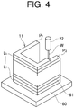
- FIG. 4 illustrates a case of forming the additively manufactured object 11 that is a modified example, in which the start position PI and the end position P2 of the molten beads of respective layers deposited are different. Also in this case, deposition of the molten bead 61 of a next layer is started when the temperature of the molten bead 61 of a previous layer falls to be equal to or lower than the allowable interpass temperature Tp.
- the deposition time tf of the molten bead 61 per layer may be set to be equal to or more than the cooling time tc, but when the total of the deposition time tf of the molten bead 61 per layer and the travel time of the welding torch 22 is set to be not less than the cooling time tc, the production efficiency can be more enhanced.
- the built-up object 11 may be formed by monitoring the temperature of each layer of the built-up model 11A and acquiring the cooling time.
- a filler metal is melted and solidified using an arc, and a plurality of layers of molten beads 61 are deposited and formed to create the same built-up model 11A as the built-up object 11.
- the temperature of the molten bead 61 of each layer in the built-up model 11A is monitored.
- each cooling time until the temperature of the molten bead 61 of each layer in the built-up model 11A is cooled down to the allowable interpass temperature from the temperature at the start of deposition is acquired by measurement or calculation.
- Deposition of the molten bead 61 of a next layer relative to the molten bead 61 of a previous layer in the built-up object 11 is started when the time from the start of deposition of the molten bead 61 of a previous layer in the built-up model 11A becomes equal to or more than the cooling time of the previous layer. Also by such a production method of the first modified example, additive manufacturing by stable arc can be achieved while ensuring deposition precision.
- the deposition time tf of the molten bead per layer in the built-up object 11 is, similarly to this embodiment, set to the cooling time, the production efficiency can be enhanced.
- the deposition time of the molten bead 61 of each layer in forming the built-up model 11A is set to be longer than the deposition time in forming the built-up object 11 so as to unfailingly prevent the built-up model 11A from becoming unstable.
- the cooling time until the temperature of the molten bead of each layer is cooled down to the allowable interpass temperature from the temperature at the start of deposition may be calculated by simulation analysis.
- the production method for an additively manufactured object as a second modified example includes a step of analyzing the cooling time until the temperature of the molten bead 61 of each layer is cooled down to the allowable interpass temperature from the temperature at the start of deposition, and deposition of the molten bead 61 of a next layer relative to each layer is started when the time from the start of deposition of the molten bead 61 of each layer becomes equal to or more than the cooling time of each layer.
- the number of welding torches 22 in depositing the molten bead 61 is set to an integer value of the quotient obtained by dividing the deposition time tf of the molten bead 61 per layer to be deposited using one welding torch 22, by the cooling time tc.
- the integer value of the quotient obtained by dividing the deposition time tf of the molten bead 61 per layer with one welding torch 22 by the cooling time tc is 2, the deposition is performed using two welding torches 22.
- cooling time tc a cooling time until the molten bead 61 of a previous layer is cooled to the allowable interpass temperature from the temperature at the start of deposition is measured, and the number of welding torches 22 is determined when the molten bead 61 of a next layer is deposited.
- cooling times until the molten beads 61 of all layers are cooled to the allowable interpass temperature from the temperature at the start of deposition may be measured when a first built-up object is manufactured, the longest cooling time may be set as the cooling time tc, and the number of welding torches 22 in manufacturing second and subsequent built-up objects may be set based on the cooling time tc.
- the temperature sensor 30 may be configured to monitor the temperature at the deposition start position of each layer, and in the case where the cooling time until the temperature of the measured molten bead 61 reaches the allowable interpass temperature is predictable in advance, deposition of the molten bead of a next layer may be started based on the predicted cooling time tc.
- the temperature of the molten bead 61 may be monitored at a plurality of sites and in this case, it is preferred that at each monitoring site, the temperature is equal to or lower than the allowable interpass temperature when the molten bead of a next layer is deposited.
Landscapes
- Engineering & Computer Science (AREA)
- Chemical & Material Sciences (AREA)
- Manufacturing & Machinery (AREA)
- Materials Engineering (AREA)
- Mechanical Engineering (AREA)
- Plasma & Fusion (AREA)
- Physics & Mathematics (AREA)
- Automation & Control Theory (AREA)
- Health & Medical Sciences (AREA)
- General Health & Medical Sciences (AREA)
- Toxicology (AREA)
- Analytical Chemistry (AREA)
- Arc Welding In General (AREA)
- Powder Metallurgy (AREA)
Abstract
Description
- The present invention relates to a production method and production system for an additively manufactured object. More specifically, the present invention relates to a production method and production system for an additively manufactured object, in which a filler metal is melted and solidified using an arc to perform additive manufacturing.
- In recent years, there is a growing need for a 3D printer as production means, and particularly regarding application to a metal material, researches and developments toward practical application are made in aircraft industry, etc. A 3D printer using a metal material is configured to shape a built-up object by melting a metal powder or a metal wire by use of a heat source such as a laser or an arc, and depositing the molten metal.
- Conventionally, as a technique for shaping a built-up object by depositing a molten metal, a technique of producing a metal mold by using a weld bead is known (see, for example, Patent Literature 1).
Patent Literature 1 describes a method for producing a metal mold, including generating profile data representing the profile of a metal mold, dividing a metal mold into multilayers along contour lines based on the generated profile data, and creating a travel path of a welding torch for supplying a filler metal based on the obtained profile data of multilayers. - In addition, conventionally, as a method for joining pipes to each other by welding, a multilayer welding method as follows is known: in order to enhance the welding efficiency, a welding torch ceasing to generate an arc is moved to a position corresponding to the shortest distance not exceeding the limit of interpass temperature with respect to a weld bead formed in the weld pass of a previous layer and welds a next layer (see, for example, Patent Literature 2).
-
- Patent Literature 1: Japanese Patent No.
3784539 - Patent Literature 2:
JP-A-2016-22480 - Meanwhile, in the additive manufacturing method using an arc, the heat input amount is large compared with a laser and the deposition efficiency (buildup amount per unit time) is high, and as a result, the cooling rate is low. As illustrated in
FIG. 6A , when an additively manufacturedobject 100 is formed by depositing N layers ofweld bead 102 by use of awelding torch 101, if the temperature of theweld bead 103 of the (N-1)-th layer remains high in depositing aweld bead 104 of the N-th layer, a problem such as flattening (seeFIG. 6B ) or running down (seeFIG. 6C ) of thebead 104 of the N-th layer occurs, so that the deposition is made unstable. On the other hand, if the deposition time is prolonged, the problem of flattening or running down of thebead 104 is not caused, but there is a problem of reducing the deposition productivity, and the deposition time per layer needs to be shortened so as to enhance the productivity. - In the production method of
Patent Literature 1, the above-described problems are not taken into consideration. Patent Literature 2 is not a technique relating to additive manufacturing and since a weld pass of a next layer is performed from a position which is distant by the shortest distance with respect to a weld bead formed in the weld pass of a previous layer as long as the limit of interpass temperature is not exceeded, the technique cannot deal with additive manufacturing that is performed by aligning the end part positions to each other. - The present invention has been made in consideration of those problems, and an object of the present invention is to provide a production method and production system for an additively manufactured object, each of which enables stable deposition while ensuring deposition precision.
- The object of the present invention can be achieved by the following configurations.
- (1) A method for producing an additively manufactured object, including melting and solidifying a filler metal by use of an arc, and depositing and forming a plurality of layers of molten beads to produce a built-up object, the method including:
- depositing the molten bead of a previous layer, and
- monitoring a temperature of the molten bead of the previous layer,
- in which deposition of the molten bead of a next layer is started when the temperature of the molten bead of the previous layer is equal to or lower than an allowable interpass temperature.
- (2) The method for producing an additively manufactured object according to (1), further including measuring a cooling time until the temperature of the molten bead of the previous layer is cooled down to the allowable interpass temperature from a temperature at a start of deposition,
in which a deposition time of the molten bead per layer is set to be not less than the cooling time. - (3) The method for producing an additively manufactured object according to (2), in which the deposition time of the molten bead per layer is set to be the cooling time.
- (4) A method for producing an additively manufactured object, including melting and solidifying a filler metal by use of an arc, and depositing and forming a plurality of layers of molten beads to produce a built-up object, the method including:
- depositing the molten bead,
- monitoring a temperature of the molten bead, and
- measuring a cooling time until the temperature of the molten bead is cooled down to an allowable interpass temperature from a temperature at a start of deposition,
- in which the number of welding torches in depositing the molten bead is set to an integer value of a quotient obtained by dividing a deposition time of the molten bead per layer by the cooling time.
- (5) The method for producing an additively manufactured object according to any one of (2) to (4),
in which the deposition time of the molten bead per layer is adjusted by changing at least one of current, voltage and welding speed during the depositing while a heat input amount per unit length of the molten bead during the depositing is kept constant. - (6) The method for producing an additively manufactured object according to any one of (2) to (4),
in which the deposition time of the molten bead per layer is adjusted by changing at least one of current, voltage and welding speed during the depositing so that a cross-sectional area of the molten bead during the depositing is kept constant. - (7) A system for producing an additively manufactured object, including depositing and forming a plurality of layers of molten beads to produce a built-up object, the system including:
- a deposition device configured to melt and solidify a filler metal by use of an arc based on layer profile data representing a profile of each layer obtained by dividing the built-up object into a plurality of mutually parallel layers, and deposit and form a plurality of layers of the molten bead,
- a temperature sensor configured to measure a temperature of the molten bead every time the molten bead is formed, and
- a control device configured to control the deposition device so that deposition of the molten bead of a next layer is started when a temperature of the molten bead of a previous layer is equal to or lower than an allowable interpass temperature.
- According to the production method and production system for an additively manufactured object of the present invention, a molten bead of a previous layer is deposited, and the temperature of the molten bead of the previous layer is monitored by a temperature sensor. Deposition of the molten bead of a next layer is started when the temperature of the molten bead of the previous layer falls to be equal to or lower than the allowable interpass temperature. According to this configuration, stable additive manufacturing by an arc can be achieved while ensuring deposition precision.
- In addition, according to the production method for an additively manufactured object of the present invention, a molten bead is deposited, the temperature of the molten bead is monitored by a temperature sensor, and furthermore, the cooling time until the temperature of the molten bead is cooled down to the allowable interpass temperature from the temperature at the start of deposition. Then, the number of welding torches in depositing the molten bead is set to an integer value of the quotient obtained by dividing the deposition time of the molten bead per layer by the cooling time. According to this configuration, an additively manufactured object can be shaped with good efficiency.
-
- [
FIG. 1] FIG. 1 is a schematic view of the configuration of the production system for an additively manufactured object according to a first embodiment of the present invention. - [
FIG. 2] FIG. 2 is a perspective view of a cylindrical additively-manufactured object produced by the production system for an additively manufactured object illustrated inFIG. 1 . - [
FIG. 3] FIG. 3 is a graph illustrating the relationship between the deposition time interval of the molten bead with the unit deposition height and the saturation temperature of the top layer. - [
FIG. 4] FIG. 4 is a perspective view of a U-shaped additively-manufactured object produced by the production system for an additively manufactured object. - [
FIG. 5] FIG. 5 is a schematic view of the configuration of the production system for an additively manufactured object according to a second embodiment of the present invention. - [
FIG. 6A] FIG. 6A is a side view illustrating how an additively manufactured object is shaped with a plurality of layers (N layers) of molten beads. - [
FIG. 6B] FIG. 6B is a schematic view illustrating a case where a molten bead is flattened due to depositing a molten bead while the temperature of the molten bead of a previous layer is high. - [
FIG. 6C] FIG. 6C is a schematic view illustrating a case where running down of a molten bead is caused due to depositing a molten bead while the temperature of the molten bead of a previous layer is high. - The production method and production system for an additively manufactured object according to each embodiment of the present invention are described in detail below based on drawings. The following embodiments are examples embodying the present invention and are not intended to limit the technical scope of the present invention.
- As illustrated in
FIG. 1 , theproduction system 10 for an additively manufactured object of this embodiment includes awelding robot 20, atemperature sensor 30, acontrol device 50, a CAD/CAM device 51, atrack planning unit 52, and amemory 53. That is, in this embodiment, an existingwelding robot 20 is used as the deposition device. - Referring also to
FIG. 2 , in theproduction system 10 for an additively manufactured object, awelding torch 22 is moved based on the layer profile data representing the profile of each of layers LI ... Lk of an additively manufacturedobject 11 while melting a filler metal (wire) W by thewelding robot 20, and amolten bead 61 is deposited over a plurality of layers LI ... Lk to shape the additively manufacturedobject 11. - The additively manufactured
object 11 illustrated inFIG. 1 andFIG. 2 is an example in which themolten bead 61 is continuously and spirally deposited (that is, the end of themolten bead 61 of a previous layer is continuous to the start of themolten bead 61 of a next layer) and is thereby molded into a substantially cylindrical shape, but the additively manufacturedobject 11 can be set to any shape. - The
welding robot 20 is an articulated robot and includes thewelding torch 22 at the tip of a leadingarm 21. The leadingarm 21 is three-dimensionally movable, and thewelding torch 22 can move to any position in any posture by controlling the posture and position of the leadingarm 21 by thecontrol device 50. - The
welding torch 22 includes a substantially tubular shield nozzle to which a shielding gas is supplied, a contact tip (not shown) disposed inside the shield nozzle, and a filler metal W held in the contact tip and supplied with a melting current. Thewelding torch 22 generates an arc to melt and solidify the filler metal W while feeding the filler metal W and flowing a shielding gas, and themolten bead 61 is deposited on asubstrate 60 to form the additively manufacturedobject 11. Thewelding torch 22 may employ a non-consumable electrode with which a filter metal is supplied from the outside. - The
temperature sensor 30 measures the temperature of themolten bead 61 deposited just before, and a contact measurement sensor may be used, but since the depositedmolten bead 61 is at a high temperature, a non-contact measurement sensor such as thermoviewer or infrared temperature sensor is preferred. - In this embodiment, the
temperature sensor 30 measures the temperature at the deposition start position of each layer. - The
control device 50 controls thewelding robot 20 and thetemperature sensor 30 to deposit a plurality ofmolten beads 61, thereby shaping the additively manufacturedobject 11. - The CAD/
CAM device 51 creates profile data of the additively manufacturedobject 11 to be formed and then produces layer profile data representing the profile of each of the layers LI ... Lk by dividing the object into a plurality of layers (seeFIG. 2 ). Thetrack planning unit 52 produces a movement track for thewelding torch 22 based on the layer profile data. Thememory 53 stores the produced layer profile data, the movement track for thewelding torch 22, the interpass temperature Tp, etc. - The
control device 50 controls the movement of thewelding robot 20 based on, for example, the layer profile data, the movement track for thewelding torch 22, and the interpass temperature Tp, which are stored in thememory 53, as well as the temperature of themolten bead 61 deposited just before, which is measured by thetemperature sensor 30. In addition, thecontrol device 50 has a built-intimer 54 for measuring the cooling time tc until the temperature of themolten bead 61 of each layer is cooled down to the allowable interpass temperature Tp from the temperature at the start of shaping. - The procedure for shaping the additively manufactured
object 11 by theproduction system 10 for an additively manufactured object of this embodiment is described in detail below by referring toFIG. 2 andFIG. 3 . Here, the description is made by taking, as an example, a case of shaping a substantially cylindrical additively-manufacturedobject 11 by depositing themolten bead 61 in the vertical direction. - First, profile data representing the profile of the additively manufactured
object 11 is created by the CAD/CAM device 51, and the input profile data (CAD data) is divided into a plurality of layers L1 ... Lk to produce layer profile data representing the profile of each of the layers LI ... Lk. The layer profile data representing the profile of each of the layers L1 ... Lk serves as the movement track of thewelding torch 22, i.e., the deposition track of theweld bead 61. - Division of the profile data of the additively manufactured
object 11 into a plurality of layers is preferably division in the direction substantially orthogonal to the deposition direction of themolten bead 61. More specifically, in the case of forming the additively manufacturedobject 11 by depositing themolten bead 61 in the vertical direction, the data is divided in the horizontal direction, and in the case of forming the additively manufacturedobject 11 by depositing themolten bead 61 in the horizontal direction, the data is divided in the vertical direction. - Subsequently, the
track planning unit 52 creates a specific deposition plan for themolten bead 61, such as movement track for thewelding torch 22 in each of the layers LI ... Lk and planned height of themolten bead 61 when themolten bead 61 of each of the layers L1...Lk is deposited. - As illustrated in
FIG. 2 , thewelding robot 20 moves thewelding torch 22 along the planned movement track to deposit themolten bead 61 of a previous layer (for example, first layer L1) on thesubstrate 60, and thetemperature sensor 30 then measures the temperature of themolten bead 61 deposited. Thereafter, the cooling time tc until the temperature of themolten bead 61 at the measurement position (for example, at the start of deposition) is cooled down to the allowable interpass temperature Tp from the temperature at the start of deposition is determined. - Deposition of the
molten bead 61 of a next layer (second layer) is started when the temperature of themolten bead 61 of the previous layer (first layer) becomes equal to or lower than the allowable interpass temperature Tp. According to this configuration, themolten bead 61 of the next layer is prevented from flattening, running down, etc. After that, deposition is repeated for all layers up to the layer Lk in the same manner as above while monitoring the temperature of the previous layer, and the good additively manufacturedobject 11 can thereby be shaped. -
FIG. 3 is a graph illustrating an example of the relationship between the deposition time interval until depositing the molten bead of a next layer with the unit deposition height of the molten bead and the saturation temperature of the deposited molten bead. As the deposition time interval is shorter, the unit deposition height of the molten bead is lower. This reveals that when the deposition time interval is short, the temperature of themolten bead 61 is not cooled down to the allowable interpass temperature Tp and flattening, running down, etc. of themolten bead 61 of a next layer occurs. On the other hand, as the deposition time interval is increased, the saturation temperature of the molten bead is lowered. - In Example illustrated in
FIG. 3 , as indicated by a dashed line in the figure, the deposition time interval t when the change in the unit deposition height is substantially saturated is the cooling time tc. Accordingly, it is understood that the deposition time tf of themolten bead 61 per layer may be set to be equal to or more than the cooling time tc. - In addition, when the deposition time tf of the
molten bead 61 per layer is set to the cooling time tc, themolten bead 61 can be continuously deposited in the shortest time without temporarily stopping the arc, and the production efficiency is enhanced. - Setting of the deposition time tf of the
molten bead 61 per layer may be adjusted by changing at least one of current, voltage and welding speed during the depositing while a heat input amount per unit length of the molten bead during the depositing is kept constant. - Alternatively, setting of the deposition time tf per layer of the
molten bead 61 may be adjusted by changing at least one of current, voltage and welding speed during the depositing so that a cross-sectional area of the molten bead during the depositing is kept constant. According to this configuration, stable deposition can be achieved while maintaining high deposition efficiency and ensuring deposition precision. - As described above, according to the production method and production system for an additively manufactured object of this embodiment, a molten bead of a previous layer is deposited, and the temperature of the
molten bead 61 of the previous layer is monitored by thetemperature sensor 30. Deposition of the molten bead of a next layer is started when the temperature of themolten bead 61 of the previous layer falls to be equal to or lower than the allowable interpass temperature Tp. According to this configuration, stable additive manufacturing by an arc can be achieved while ensuring deposition precision. - More specifically, the cooling time tc, which is the time until the temperature of the
molten bead 61 of the previous layer is cooled down to the allowable interpass temperature from the temperature at the start of deposition, is measured, and the deposition time tf of themolten bead 61 per layer should be set to be equal to or more than the cooling time tc. - From the viewpoint of enhancing the production efficiency, it is preferable to set the deposition time tf so that the deposition time tf per layer is equal to or more than the cooling time tc and the difference between the deposition time tf per layer and the cooling time tc is small.
-
FIG. 4 illustrates a case of forming the additively manufacturedobject 11 that is a modified example, in which the start position PI and the end position P2 of the molten beads of respective layers deposited are different. Also in this case, deposition of themolten bead 61 of a next layer is started when the temperature of themolten bead 61 of a previous layer falls to be equal to or lower than the allowable interpass temperature Tp. - In this case, the deposition time tf of the
molten bead 61 per layer may be set to be equal to or more than the cooling time tc, but when the total of the deposition time tf of themolten bead 61 per layer and the travel time of thewelding torch 22 is set to be not less than the cooling time tc, the production efficiency can be more enhanced. - In a first modified example of this embodiment, after the same built-up
model 11A as the additively manufactured object 11 (see,FIG. 2 ) is previously formed in the same manner as the additively manufacturedobject 11, the built-upobject 11 may be formed by monitoring the temperature of each layer of the built-upmodel 11A and acquiring the cooling time. - More specifically, in the production method for an additively manufactured object as a first modified example, a filler metal is melted and solidified using an arc, and a plurality of layers of
molten beads 61 are deposited and formed to create the same built-upmodel 11A as the built-upobject 11. At this time, the temperature of themolten bead 61 of each layer in the built-upmodel 11A is monitored. Furthermore, each cooling time until the temperature of themolten bead 61 of each layer in the built-upmodel 11A is cooled down to the allowable interpass temperature from the temperature at the start of deposition is acquired by measurement or calculation. Deposition of themolten bead 61 of a next layer relative to themolten bead 61 of a previous layer in the built-upobject 11 is started when the time from the start of deposition of themolten bead 61 of a previous layer in the built-upmodel 11A becomes equal to or more than the cooling time of the previous layer. Also by such a production method of the first modified example, additive manufacturing by stable arc can be achieved while ensuring deposition precision. - In addition, when the deposition time tf of the molten bead per layer in the built-up
object 11 is, similarly to this embodiment, set to the cooling time, the production efficiency can be enhanced. - The deposition time of the
molten bead 61 of each layer in forming the built-upmodel 11A is set to be longer than the deposition time in forming the built-upobject 11 so as to unfailingly prevent the built-upmodel 11A from becoming unstable. - Furthermore, in a second modified example of this embodiment, the cooling time until the temperature of the molten bead of each layer is cooled down to the allowable interpass temperature from the temperature at the start of deposition may be calculated by simulation analysis.
- More specifically, the production method for an additively manufactured object as a second modified example includes a step of analyzing the cooling time until the temperature of the
molten bead 61 of each layer is cooled down to the allowable interpass temperature from the temperature at the start of deposition, and deposition of themolten bead 61 of a next layer relative to each layer is started when the time from the start of deposition of themolten bead 61 of each layer becomes equal to or more than the cooling time of each layer. - The production method and production system for an additively manufactured object according to a second embodiment of the present invention are described in detail below by referring to
FIG. 5 . The parts which are the same as or equivalent to the first embodiment are denoted by the same numerical references, and their descriptions are omitted or simplified. - In this embodiment, in the case where the deposition time tf of the
molten bead 61 per layer to be deposited using onewelding torch 22 is very long compared with the cooling time tc, a plurality ofmolten beads 61 are simultaneously deposited using a plurality of welding torches 22 to enhance the production efficiency. - More specifically, the number of welding torches 22 in depositing the
molten bead 61 is set to an integer value of the quotient obtained by dividing the deposition time tf of themolten bead 61 per layer to be deposited using onewelding torch 22, by the cooling time tc. For example, as illustrated inFIG. 5 , when the integer value of the quotient obtained by dividing the deposition time tf of themolten bead 61 per layer with onewelding torch 22 by the cooling time tc is 2, the deposition is performed using two welding torches 22. - In this embodiment, as for the cooling time tc, a cooling time until the
molten bead 61 of a previous layer is cooled to the allowable interpass temperature from the temperature at the start of deposition is measured, and the number of welding torches 22 is determined when themolten bead 61 of a next layer is deposited. However, in the case of manufacturing the same built-up object, cooling times until themolten beads 61 of all layers are cooled to the allowable interpass temperature from the temperature at the start of deposition may be measured when a first built-up object is manufactured, the longest cooling time may be set as the cooling time tc, and the number of welding torches 22 in manufacturing second and subsequent built-up objects may be set based on the cooling time tc. - Other configurations and actions are the same as those of the first embodiment.
- The present invention is not limited to the above-described embodiments, and modifications, improvements, etc. can be appropriately made therein.
- For example, the
temperature sensor 30 may be configured to monitor the temperature at the deposition start position of each layer, and in the case where the cooling time until the temperature of the measuredmolten bead 61 reaches the allowable interpass temperature is predictable in advance, deposition of the molten bead of a next layer may be started based on the predicted cooling time tc. - In addition, the temperature of the
molten bead 61 may be monitored at a plurality of sites and in this case, it is preferred that at each monitoring site, the temperature is equal to or lower than the allowable interpass temperature when the molten bead of a next layer is deposited. - This application is based on Japanese Patent Application No.
2017-061063 filed on March 27, 2017 -
- 10
- Production system for additively manufactured object
- 11
- Additively manufactured object (built-up object)
- 11A
- Built-up model
- 20
- Welding robot (deposition device)
- 30
- Temperature sensor
- 50
- Control device
- 61
- Molten bead
- L1...Lk
- Layer
- tc
- Cooling time
- tf
- Deposition time of molten bead per layer
- Tp
- Interpass temperature
Claims (7)
- A method for producing an additively manufactured object, comprising melting and solidifying a filler metal by use of an arc, and depositing and forming a plurality of layers of molten beads to produce a built-up object,
the method comprising:depositing the molten bead of a previous layer; andmonitoring a temperature of the molten bead of the previous layer,wherein deposition of the molten bead of a next layer is started when the temperature of the molten bead of the previous layer is equal to or lower than an allowable interpass temperature. - The method for producing an additively manufactured object according to Claim 1, further comprising measuring a cooling time until the temperature of the molten bead of the previous layer is cooled down to the allowable interpass temperature from a temperature at a start of deposition,
wherein a deposition time of the molten bead per layer is set to be not less than the cooling time. - The method for producing an additively manufactured object according to Claim 2, wherein the deposition time of the molten bead per layer is set to be the cooling time.
- A method for producing an additively manufactured object, comprising melting and solidifying a filler metal by use of an arc, and depositing and forming a plurality of layers of molten beads to produce a built-up object,
the method comprising:depositing the molten bead;monitoring a temperature of the molten bead; andmeasuring a cooling time until the temperature of the molten bead is cooled down to an allowable interpass temperature from a temperature at a start of deposition,wherein the number of welding torches in depositing the molten bead is set to an integer value of a quotient obtained by dividing a deposition time of the molten bead per layer by the cooling time. - The method for producing an additively manufactured object according to any one of Claims 2 to 4,
wherein the deposition time of the molten bead per layer is adjusted by changing at least one of current, voltage and welding speed during the depositing while a heat input amount per unit length of the molten bead during the depositing is kept constant. - The method for producing an additively manufactured object according to any one of Claims 2 to 4,
wherein the deposition time of the molten bead per layer is adjusted by changing at least one of current, voltage and welding speed during the depositing so that a cross-sectional area of the molten bead during the depositing is kept constant. - A system for producing an additively manufactured object, depositing and forming a plurality of layers of molten beads to produce a built-up object,
the system comprising:a deposition device configured to melt and solidify a filler metal by use of an arc based on layer profile data representing a profile of each layer obtained by dividing the built-up object into a plurality of mutually parallel layers, and deposit and form a plurality of layers of the molten beads;a temperature sensor configured to measure a temperature of the molten bead every time the molten bead is formed; anda control device configured to control the deposition device so that deposition of the molten bead of a next layer is started when a temperature of the molten bead of a previous layer is equal to or lower than an allowable interpass temperature.
Applications Claiming Priority (2)
| Application Number | Priority Date | Filing Date | Title |
|---|---|---|---|
| JP2017061063A JP6822881B2 (en) | 2017-03-27 | 2017-03-27 | Manufacturing method and manufacturing system for laminated models |
| PCT/JP2018/007375 WO2018180135A1 (en) | 2017-03-27 | 2018-02-27 | Method and system for manufacturing laminated shaped product |
Publications (3)
| Publication Number | Publication Date |
|---|---|
| EP3608042A1 true EP3608042A1 (en) | 2020-02-12 |
| EP3608042A4 EP3608042A4 (en) | 2020-08-12 |
| EP3608042B1 EP3608042B1 (en) | 2022-08-17 |
Family
ID=63675313
Family Applications (1)
| Application Number | Title | Priority Date | Filing Date |
|---|---|---|---|
| EP18777928.5A Active EP3608042B1 (en) | 2017-03-27 | 2018-02-27 | Method and system for manufacturing laminated shaped product |
Country Status (5)
| Country | Link |
|---|---|
| US (1) | US11273511B2 (en) |
| EP (1) | EP3608042B1 (en) |
| JP (1) | JP6822881B2 (en) |
| CN (1) | CN110461509B (en) |
| WO (1) | WO2018180135A1 (en) |
Families Citing this family (7)
| Publication number | Priority date | Publication date | Assignee | Title |
|---|---|---|---|---|
| JP6964539B2 (en) * | 2017-09-15 | 2021-11-10 | 株式会社神戸製鋼所 | Laminated model and manufacturing method of laminated model |
| EP3682996B1 (en) * | 2017-09-15 | 2022-06-29 | Kabushiki Kaisha Kobe Seiko Sho (Kobe Steel, Ltd.) | Laminated molding and method of manufacturing laminated molding |
| JP7232113B2 (en) | 2019-04-11 | 2023-03-02 | 三菱重工コンプレッサ株式会社 | metal additive manufacturing method |
| JP7144357B2 (en) * | 2019-05-29 | 2022-09-29 | 株式会社神戸製鋼所 | Modeled object manufacturing method, modeled object manufacturing procedure generation method, modeled object manufacturing system, modeled object manufacturing procedure generation device, and program |
| WO2021029297A1 (en) * | 2019-08-09 | 2021-02-18 | 株式会社神戸製鋼所 | Lamination planning method for laminate molded object, and laminate molded object manufacturing method and manufacturing device |
| US20220324047A1 (en) * | 2021-04-09 | 2022-10-13 | National Oilwell Varco, L.P. | Systems and methods for wire arc additive manufacturing |
| JP2022188817A (en) * | 2021-06-10 | 2022-12-22 | 株式会社日立製作所 | Method for manufacturing laminated molded article and laminate molding apparatus |
Family Cites Families (23)
| Publication number | Priority date | Publication date | Assignee | Title |
|---|---|---|---|---|
| JP3207533B2 (en) * | 1992-07-06 | 2001-09-10 | ファナック株式会社 | Control device and control method for spot welding |
| JP3784539B2 (en) | 1998-07-01 | 2006-06-14 | 本田技研工業株式会社 | Mold manufacturing method |
| BRPI0114859B1 (en) * | 2000-10-24 | 2015-12-22 | Saipem Spa | method of laying a submerged pipe |
| EP1795326A4 (en) * | 2004-09-30 | 2011-10-19 | Toray Industries | Apparatus and method for manufacturing laminated sheet |
| US8629368B2 (en) * | 2006-01-30 | 2014-01-14 | Dm3D Technology, Llc | High-speed, ultra precision manufacturing station that combines direct metal deposition and EDM |
| CN101391338B (en) * | 2008-10-17 | 2010-12-22 | 哈尔滨建成集团有限公司 | Ferritic steel barrel butt-junction circular-seam hot-wire TIG multi-layer multipath welding method |
| JP2010201474A (en) * | 2009-03-04 | 2010-09-16 | Toshiba Corp | Method and system for optimization of welding, and welding method |
| GB2472783B (en) | 2009-08-14 | 2012-05-23 | Norsk Titanium Components As | Device for manufacturing titanium objects |
| CN101905802B (en) * | 2010-07-26 | 2012-05-30 | 章鹏 | Manufacturing method of cladding type threaded component for parallel double-screw extruder |
| JP5956455B2 (en) * | 2010-11-28 | 2016-07-27 | ストラタシス リミテッド | System and method for additive manufacturing of objects |
| CN102744494A (en) * | 2012-07-15 | 2012-10-24 | 沈阳工业大学 | Device and method for measuring heat distribution of welding arc |
| CN102941394B (en) | 2012-11-15 | 2015-04-01 | 武汉船用机械有限责任公司 | Method for overlaying welding of duplex stainless steel |
| US10464168B2 (en) * | 2014-01-24 | 2019-11-05 | Lincoln Global, Inc. | Method and system for additive manufacturing using high energy source and hot-wire |
| CN106662439B (en) * | 2014-06-05 | 2019-04-09 | 联邦科学和工业研究组织 | The prediction and minimum deformed in increasing material manufacturing |
| JP2016022480A (en) | 2014-07-16 | 2016-02-08 | 株式会社Ihi | Multi-layer welding method and multi-layer welding device |
| CN104526114B (en) * | 2014-11-04 | 2017-08-25 | 南方增材科技有限公司 | A kind of hardware submerged arc overlay welding manufacturing process |
| CN104526171B (en) * | 2014-11-04 | 2016-10-12 | 南方增材科技有限公司 | Hardware electric smelting manufacturing process |
| CN104690404B (en) | 2015-03-19 | 2016-08-31 | 中国神华能源股份有限公司 | The welding method of T22 and TP347H dissimilar steel |
| CN105171186A (en) | 2015-07-31 | 2015-12-23 | 武汉船用机械有限责任公司 | Welding method for conducting build up welding through stellite alloy |
| JP2017061063A (en) | 2015-09-24 | 2017-03-30 | 南部化成株式会社 | Manufacturing method of multilayer molding lens |
| DE102015117238A1 (en) * | 2015-10-09 | 2017-04-13 | GEFERTEC GmbH | Machining module for an additive manufacturing device |
| CN105921851A (en) | 2016-06-01 | 2016-09-07 | 西安铂力特激光成形技术有限公司 | Arc-welding material additive manufacturing method for stainless steel part |
| CN106112206B (en) * | 2016-07-22 | 2019-08-16 | 天津津航技术物理研究所 | A kind of multi-shaft interlocked formula metal 3D printer and Method of printing based on arc-welding method |
-
2017
- 2017-03-27 JP JP2017061063A patent/JP6822881B2/en active Active
-
2018
- 2018-02-27 WO PCT/JP2018/007375 patent/WO2018180135A1/en unknown
- 2018-02-27 CN CN201880021692.4A patent/CN110461509B/en active Active
- 2018-02-27 EP EP18777928.5A patent/EP3608042B1/en active Active
- 2018-02-27 US US16/495,755 patent/US11273511B2/en active Active
Also Published As
| Publication number | Publication date |
|---|---|
| US11273511B2 (en) | 2022-03-15 |
| WO2018180135A1 (en) | 2018-10-04 |
| CN110461509B (en) | 2022-05-03 |
| JP6822881B2 (en) | 2021-01-27 |
| EP3608042A4 (en) | 2020-08-12 |
| JP2018162500A (en) | 2018-10-18 |
| CN110461509A (en) | 2019-11-15 |
| EP3608042B1 (en) | 2022-08-17 |
| US20200038983A1 (en) | 2020-02-06 |
Similar Documents
| Publication | Publication Date | Title |
|---|---|---|
| US11273511B2 (en) | Method and system for manufacturing laminated shaped product | |
| WO2018168881A1 (en) | Manufacturing method, manufacturing system, and manufacturing program for additive manufactured object | |
| EP3711887B1 (en) | Method and apparatus for manufacturing layered model | |
| EP3711888B1 (en) | Method and device for manufacturing shaped objects | |
| EP3815826A1 (en) | Laminated molded object production method and production device | |
| US11524352B2 (en) | Laminated molding and method of manufacturing laminated molding | |
| US20180178304A1 (en) | 3d printing apparatus | |
| EP3693118B1 (en) | Hybrid additive manufacturing system using laser and arc welding | |
| CN112533720A (en) | Additive manufacturing system in a controlled short circuit welding system | |
| EP4177002A1 (en) | Method for manufacturing multi-layer molded article | |
| JP2019081187A (en) | Method for manufacturing laminated shaped object | |
| EP3711889A1 (en) | Method for producing molded article, production device, and molded article | |
| JP2018086664A (en) | Welding device, welding method, three-dimensional molding apparatus, and three-dimensional molding method | |
| EP4163114A1 (en) | Manufacturing method for multi-layer molded article | |
| WO2023149142A1 (en) | Control information generating device, control information generating method, welding control device, and control information generating program | |
| US20240102798A1 (en) | Method for predicting deformation of additively manufactured object | |
| US11806820B2 (en) | Laminated molding and method of manufacturing laminated molding |
Legal Events
| Date | Code | Title | Description |
|---|---|---|---|
| STAA | Information on the status of an ep patent application or granted ep patent |
Free format text: STATUS: THE INTERNATIONAL PUBLICATION HAS BEEN MADE |
|
| PUAI | Public reference made under article 153(3) epc to a published international application that has entered the european phase |
Free format text: ORIGINAL CODE: 0009012 |
|
| STAA | Information on the status of an ep patent application or granted ep patent |
Free format text: STATUS: REQUEST FOR EXAMINATION WAS MADE |
|
| 17P | Request for examination filed |
Effective date: 20190910 |
|
| AK | Designated contracting states |
Kind code of ref document: A1 Designated state(s): AL AT BE BG CH CY CZ DE DK EE ES FI FR GB GR HR HU IE IS IT LI LT LU LV MC MK MT NL NO PL PT RO RS SE SI SK SM TR |
|
| AX | Request for extension of the european patent |
Extension state: BA ME |
|
| DAV | Request for validation of the european patent (deleted) | ||
| DAX | Request for extension of the european patent (deleted) | ||
| A4 | Supplementary search report drawn up and despatched |
Effective date: 20200710 |
|
| RIC1 | Information provided on ipc code assigned before grant |
Ipc: B23K 9/032 20060101ALI20200706BHEP Ipc: B33Y 10/00 20150101ALI20200706BHEP Ipc: B23K 9/04 20060101ALI20200706BHEP Ipc: B33Y 30/00 20150101ALI20200706BHEP Ipc: B33Y 50/02 20150101ALI20200706BHEP Ipc: B22F 3/16 20060101AFI20200706BHEP Ipc: B23K 9/095 20060101ALI20200706BHEP Ipc: B22F 3/105 20060101ALI20200706BHEP |
|
| STAA | Information on the status of an ep patent application or granted ep patent |
Free format text: STATUS: EXAMINATION IS IN PROGRESS |
|
| 17Q | First examination report despatched |
Effective date: 20210625 |
|
| REG | Reference to a national code |
Ref country code: DE Ref legal event code: R079 Ref document number: 602018039456 Country of ref document: DE Free format text: PREVIOUS MAIN CLASS: B22F0003160000 Ipc: B22F0010250000 |
|
| GRAP | Despatch of communication of intention to grant a patent |
Free format text: ORIGINAL CODE: EPIDOSNIGR1 |
|
| STAA | Information on the status of an ep patent application or granted ep patent |
Free format text: STATUS: GRANT OF PATENT IS INTENDED |
|
| RIC1 | Information provided on ipc code assigned before grant |
Ipc: B33Y 50/02 20150101ALI20220406BHEP Ipc: B33Y 30/00 20150101ALI20220406BHEP Ipc: B33Y 10/00 20150101ALI20220406BHEP Ipc: B23K 9/173 20060101ALI20220406BHEP Ipc: B23K 9/095 20060101ALI20220406BHEP Ipc: B23K 9/04 20060101ALI20220406BHEP Ipc: B22F 12/90 20210101ALI20220406BHEP Ipc: B22F 12/45 20210101ALI20220406BHEP Ipc: B22F 10/36 20210101ALI20220406BHEP Ipc: B22F 10/25 20210101AFI20220406BHEP |
|
| INTG | Intention to grant announced |
Effective date: 20220502 |
|
| GRAS | Grant fee paid |
Free format text: ORIGINAL CODE: EPIDOSNIGR3 |
|
| GRAA | (expected) grant |
Free format text: ORIGINAL CODE: 0009210 |
|
| STAA | Information on the status of an ep patent application or granted ep patent |
Free format text: STATUS: THE PATENT HAS BEEN GRANTED |
|
| AK | Designated contracting states |
Kind code of ref document: B1 Designated state(s): AL AT BE BG CH CY CZ DE DK EE ES FI FR GB GR HR HU IE IS IT LI LT LU LV MC MK MT NL NO PL PT RO RS SE SI SK SM TR |
|
| REG | Reference to a national code |
Ref country code: CH Ref legal event code: EP |
|
| REG | Reference to a national code |
Ref country code: DE Ref legal event code: R096 Ref document number: 602018039456 Country of ref document: DE |
|
| REG | Reference to a national code |
Ref country code: IE Ref legal event code: FG4D |
|
| REG | Reference to a national code |
Ref country code: AT Ref legal event code: REF Ref document number: 1511837 Country of ref document: AT Kind code of ref document: T Effective date: 20220915 |
|
| REG | Reference to a national code |
Ref country code: NL Ref legal event code: MP Effective date: 20220817 |
|
| REG | Reference to a national code |
Ref country code: LT Ref legal event code: MG9D |
|
| PG25 | Lapsed in a contracting state [announced via postgrant information from national office to epo] |
Ref country code: SE Free format text: LAPSE BECAUSE OF FAILURE TO SUBMIT A TRANSLATION OF THE DESCRIPTION OR TO PAY THE FEE WITHIN THE PRESCRIBED TIME-LIMIT Effective date: 20220817 Ref country code: RS Free format text: LAPSE BECAUSE OF FAILURE TO SUBMIT A TRANSLATION OF THE DESCRIPTION OR TO PAY THE FEE WITHIN THE PRESCRIBED TIME-LIMIT Effective date: 20220817 Ref country code: PT Free format text: LAPSE BECAUSE OF FAILURE TO SUBMIT A TRANSLATION OF THE DESCRIPTION OR TO PAY THE FEE WITHIN THE PRESCRIBED TIME-LIMIT Effective date: 20221219 Ref country code: NO Free format text: LAPSE BECAUSE OF FAILURE TO SUBMIT A TRANSLATION OF THE DESCRIPTION OR TO PAY THE FEE WITHIN THE PRESCRIBED TIME-LIMIT Effective date: 20221117 Ref country code: NL Free format text: LAPSE BECAUSE OF FAILURE TO SUBMIT A TRANSLATION OF THE DESCRIPTION OR TO PAY THE FEE WITHIN THE PRESCRIBED TIME-LIMIT Effective date: 20220817 Ref country code: LV Free format text: LAPSE BECAUSE OF FAILURE TO SUBMIT A TRANSLATION OF THE DESCRIPTION OR TO PAY THE FEE WITHIN THE PRESCRIBED TIME-LIMIT Effective date: 20220817 Ref country code: LT Free format text: LAPSE BECAUSE OF FAILURE TO SUBMIT A TRANSLATION OF THE DESCRIPTION OR TO PAY THE FEE WITHIN THE PRESCRIBED TIME-LIMIT Effective date: 20220817 Ref country code: FI Free format text: LAPSE BECAUSE OF FAILURE TO SUBMIT A TRANSLATION OF THE DESCRIPTION OR TO PAY THE FEE WITHIN THE PRESCRIBED TIME-LIMIT Effective date: 20220817 |
|
| REG | Reference to a national code |
Ref country code: AT Ref legal event code: MK05 Ref document number: 1511837 Country of ref document: AT Kind code of ref document: T Effective date: 20220817 |
|
| PG25 | Lapsed in a contracting state [announced via postgrant information from national office to epo] |
Ref country code: PL Free format text: LAPSE BECAUSE OF FAILURE TO SUBMIT A TRANSLATION OF THE DESCRIPTION OR TO PAY THE FEE WITHIN THE PRESCRIBED TIME-LIMIT Effective date: 20220817 Ref country code: IS Free format text: LAPSE BECAUSE OF FAILURE TO SUBMIT A TRANSLATION OF THE DESCRIPTION OR TO PAY THE FEE WITHIN THE PRESCRIBED TIME-LIMIT Effective date: 20221217 Ref country code: HR Free format text: LAPSE BECAUSE OF FAILURE TO SUBMIT A TRANSLATION OF THE DESCRIPTION OR TO PAY THE FEE WITHIN THE PRESCRIBED TIME-LIMIT Effective date: 20220817 Ref country code: GR Free format text: LAPSE BECAUSE OF FAILURE TO SUBMIT A TRANSLATION OF THE DESCRIPTION OR TO PAY THE FEE WITHIN THE PRESCRIBED TIME-LIMIT Effective date: 20221118 |
|
| PG25 | Lapsed in a contracting state [announced via postgrant information from national office to epo] |
Ref country code: SM Free format text: LAPSE BECAUSE OF FAILURE TO SUBMIT A TRANSLATION OF THE DESCRIPTION OR TO PAY THE FEE WITHIN THE PRESCRIBED TIME-LIMIT Effective date: 20220817 Ref country code: RO Free format text: LAPSE BECAUSE OF FAILURE TO SUBMIT A TRANSLATION OF THE DESCRIPTION OR TO PAY THE FEE WITHIN THE PRESCRIBED TIME-LIMIT Effective date: 20220817 Ref country code: ES Free format text: LAPSE BECAUSE OF FAILURE TO SUBMIT A TRANSLATION OF THE DESCRIPTION OR TO PAY THE FEE WITHIN THE PRESCRIBED TIME-LIMIT Effective date: 20220817 Ref country code: DK Free format text: LAPSE BECAUSE OF FAILURE TO SUBMIT A TRANSLATION OF THE DESCRIPTION OR TO PAY THE FEE WITHIN THE PRESCRIBED TIME-LIMIT Effective date: 20220817 Ref country code: CZ Free format text: LAPSE BECAUSE OF FAILURE TO SUBMIT A TRANSLATION OF THE DESCRIPTION OR TO PAY THE FEE WITHIN THE PRESCRIBED TIME-LIMIT Effective date: 20220817 Ref country code: AT Free format text: LAPSE BECAUSE OF FAILURE TO SUBMIT A TRANSLATION OF THE DESCRIPTION OR TO PAY THE FEE WITHIN THE PRESCRIBED TIME-LIMIT Effective date: 20220817 |
|
| REG | Reference to a national code |
Ref country code: DE Ref legal event code: R097 Ref document number: 602018039456 Country of ref document: DE |
|
| PG25 | Lapsed in a contracting state [announced via postgrant information from national office to epo] |
Ref country code: SK Free format text: LAPSE BECAUSE OF FAILURE TO SUBMIT A TRANSLATION OF THE DESCRIPTION OR TO PAY THE FEE WITHIN THE PRESCRIBED TIME-LIMIT Effective date: 20220817 Ref country code: EE Free format text: LAPSE BECAUSE OF FAILURE TO SUBMIT A TRANSLATION OF THE DESCRIPTION OR TO PAY THE FEE WITHIN THE PRESCRIBED TIME-LIMIT Effective date: 20220817 |
|
| PLBE | No opposition filed within time limit |
Free format text: ORIGINAL CODE: 0009261 |
|
| STAA | Information on the status of an ep patent application or granted ep patent |
Free format text: STATUS: NO OPPOSITION FILED WITHIN TIME LIMIT |
|
| P01 | Opt-out of the competence of the unified patent court (upc) registered |
Effective date: 20230523 |
|
| PG25 | Lapsed in a contracting state [announced via postgrant information from national office to epo] |
Ref country code: AL Free format text: LAPSE BECAUSE OF FAILURE TO SUBMIT A TRANSLATION OF THE DESCRIPTION OR TO PAY THE FEE WITHIN THE PRESCRIBED TIME-LIMIT Effective date: 20220817 |
|
| 26N | No opposition filed |
Effective date: 20230519 |
|
| PG25 | Lapsed in a contracting state [announced via postgrant information from national office to epo] |
Ref country code: SI Free format text: LAPSE BECAUSE OF FAILURE TO SUBMIT A TRANSLATION OF THE DESCRIPTION OR TO PAY THE FEE WITHIN THE PRESCRIBED TIME-LIMIT Effective date: 20220817 |
|
| PG25 | Lapsed in a contracting state [announced via postgrant information from national office to epo] |
Ref country code: MC Free format text: LAPSE BECAUSE OF FAILURE TO SUBMIT A TRANSLATION OF THE DESCRIPTION OR TO PAY THE FEE WITHIN THE PRESCRIBED TIME-LIMIT Effective date: 20220817 |
|
| REG | Reference to a national code |
Ref country code: CH Ref legal event code: PL |
|
| REG | Reference to a national code |
Ref country code: BE Ref legal event code: MM Effective date: 20230228 |
|
| PG25 | Lapsed in a contracting state [announced via postgrant information from national office to epo] |
Ref country code: LU Free format text: LAPSE BECAUSE OF NON-PAYMENT OF DUE FEES Effective date: 20230227 Ref country code: LI Free format text: LAPSE BECAUSE OF NON-PAYMENT OF DUE FEES Effective date: 20230228 Ref country code: CH Free format text: LAPSE BECAUSE OF NON-PAYMENT OF DUE FEES Effective date: 20230228 |
|
| REG | Reference to a national code |
Ref country code: IE Ref legal event code: MM4A |
|
| PG25 | Lapsed in a contracting state [announced via postgrant information from national office to epo] |
Ref country code: IE Free format text: LAPSE BECAUSE OF NON-PAYMENT OF DUE FEES Effective date: 20230227 |
|
| PG25 | Lapsed in a contracting state [announced via postgrant information from national office to epo] |
Ref country code: BE Free format text: LAPSE BECAUSE OF NON-PAYMENT OF DUE FEES Effective date: 20230228 |
|
| PGFP | Annual fee paid to national office [announced via postgrant information from national office to epo] |
Ref country code: DE Payment date: 20231229 Year of fee payment: 7 Ref country code: GB Payment date: 20240108 Year of fee payment: 7 |
|
| PG25 | Lapsed in a contracting state [announced via postgrant information from national office to epo] |
Ref country code: IT Free format text: LAPSE BECAUSE OF FAILURE TO SUBMIT A TRANSLATION OF THE DESCRIPTION OR TO PAY THE FEE WITHIN THE PRESCRIBED TIME-LIMIT Effective date: 20220817 |
|
| PGFP | Annual fee paid to national office [announced via postgrant information from national office to epo] |
Ref country code: FR Payment date: 20240103 Year of fee payment: 7 |