EP3607282B1 - Verfahren zur messung der in ein reservoir und einer und füllstation eingeleiteten gasmenge - Google Patents
Verfahren zur messung der in ein reservoir und einer und füllstation eingeleiteten gasmenge Download PDFInfo
- Publication number
- EP3607282B1 EP3607282B1 EP18718886.7A EP18718886A EP3607282B1 EP 3607282 B1 EP3607282 B1 EP 3607282B1 EP 18718886 A EP18718886 A EP 18718886A EP 3607282 B1 EP3607282 B1 EP 3607282B1
- Authority
- EP
- European Patent Office
- Prior art keywords
- gas
- tank
- filling pipe
- flow meter
- downstream
- Prior art date
- Legal status (The legal status is an assumption and is not a legal conclusion. Google has not performed a legal analysis and makes no representation as to the accuracy of the status listed.)
- Active
Links
Images
Classifications
-
- G—PHYSICS
- G01—MEASURING; TESTING
- G01F—MEASURING VOLUME, VOLUME FLOW, MASS FLOW OR LIQUID LEVEL; METERING BY VOLUME
- G01F13/00—Apparatus for measuring by volume and delivering fluids or fluent solid materials, not provided for in the preceding groups
- G01F13/006—Apparatus for measuring by volume and delivering fluids or fluent solid materials, not provided for in the preceding groups measuring volume in function of time
-
- F—MECHANICAL ENGINEERING; LIGHTING; HEATING; WEAPONS; BLASTING
- F17—STORING OR DISTRIBUTING GASES OR LIQUIDS
- F17C—VESSELS FOR CONTAINING OR STORING COMPRESSED, LIQUEFIED OR SOLIDIFIED GASES; FIXED-CAPACITY GAS-HOLDERS; FILLING VESSELS WITH, OR DISCHARGING FROM VESSELS, COMPRESSED, LIQUEFIED, OR SOLIDIFIED GASES
- F17C13/00—Details of vessels or of the filling or discharging of vessels
- F17C13/02—Special adaptations of indicating, measuring, or monitoring equipment
-
- F—MECHANICAL ENGINEERING; LIGHTING; HEATING; WEAPONS; BLASTING
- F17—STORING OR DISTRIBUTING GASES OR LIQUIDS
- F17C—VESSELS FOR CONTAINING OR STORING COMPRESSED, LIQUEFIED OR SOLIDIFIED GASES; FIXED-CAPACITY GAS-HOLDERS; FILLING VESSELS WITH, OR DISCHARGING FROM VESSELS, COMPRESSED, LIQUEFIED, OR SOLIDIFIED GASES
- F17C5/00—Methods or apparatus for filling containers with liquefied, solidified, or compressed gases under pressures
- F17C5/06—Methods or apparatus for filling containers with liquefied, solidified, or compressed gases under pressures for filling with compressed gases
-
- G—PHYSICS
- G01—MEASURING; TESTING
- G01F—MEASURING VOLUME, VOLUME FLOW, MASS FLOW OR LIQUID LEVEL; METERING BY VOLUME
- G01F15/00—Details of, or accessories for, apparatus of groups G01F1/00 - G01F13/00 insofar as such details or appliances are not adapted to particular types of such apparatus
- G01F15/001—Means for regulating or setting the meter for a predetermined quantity
- G01F15/002—Means for regulating or setting the meter for a predetermined quantity for gases
-
- G—PHYSICS
- G01—MEASURING; TESTING
- G01F—MEASURING VOLUME, VOLUME FLOW, MASS FLOW OR LIQUID LEVEL; METERING BY VOLUME
- G01F15/00—Details of, or accessories for, apparatus of groups G01F1/00 - G01F13/00 insofar as such details or appliances are not adapted to particular types of such apparatus
- G01F15/001—Means for regulating or setting the meter for a predetermined quantity
- G01F15/003—Means for regulating or setting the meter for a predetermined quantity using electromagnetic, electric or electronic means
-
- F—MECHANICAL ENGINEERING; LIGHTING; HEATING; WEAPONS; BLASTING
- F17—STORING OR DISTRIBUTING GASES OR LIQUIDS
- F17C—VESSELS FOR CONTAINING OR STORING COMPRESSED, LIQUEFIED OR SOLIDIFIED GASES; FIXED-CAPACITY GAS-HOLDERS; FILLING VESSELS WITH, OR DISCHARGING FROM VESSELS, COMPRESSED, LIQUEFIED, OR SOLIDIFIED GASES
- F17C2203/00—Vessel construction, in particular walls or details thereof
- F17C2203/06—Materials for walls or layers thereof; Properties or structures of walls or their materials
- F17C2203/0634—Materials for walls or layers thereof
- F17C2203/0658—Synthetics
- F17C2203/0663—Synthetics in form of fibers or filaments
- F17C2203/0673—Polymers
-
- F—MECHANICAL ENGINEERING; LIGHTING; HEATING; WEAPONS; BLASTING
- F17—STORING OR DISTRIBUTING GASES OR LIQUIDS
- F17C—VESSELS FOR CONTAINING OR STORING COMPRESSED, LIQUEFIED OR SOLIDIFIED GASES; FIXED-CAPACITY GAS-HOLDERS; FILLING VESSELS WITH, OR DISCHARGING FROM VESSELS, COMPRESSED, LIQUEFIED, OR SOLIDIFIED GASES
- F17C2221/00—Handled fluid, in particular type of fluid
- F17C2221/01—Pure fluids
- F17C2221/012—Hydrogen
-
- F—MECHANICAL ENGINEERING; LIGHTING; HEATING; WEAPONS; BLASTING
- F17—STORING OR DISTRIBUTING GASES OR LIQUIDS
- F17C—VESSELS FOR CONTAINING OR STORING COMPRESSED, LIQUEFIED OR SOLIDIFIED GASES; FIXED-CAPACITY GAS-HOLDERS; FILLING VESSELS WITH, OR DISCHARGING FROM VESSELS, COMPRESSED, LIQUEFIED, OR SOLIDIFIED GASES
- F17C2225/00—Handled fluid after transfer, i.e. state of fluid after transfer from the vessel
- F17C2225/01—Handled fluid after transfer, i.e. state of fluid after transfer from the vessel characterised by the phase
- F17C2225/0107—Single phase
- F17C2225/0123—Single phase gaseous, e.g. CNG, GNC
-
- F—MECHANICAL ENGINEERING; LIGHTING; HEATING; WEAPONS; BLASTING
- F17—STORING OR DISTRIBUTING GASES OR LIQUIDS
- F17C—VESSELS FOR CONTAINING OR STORING COMPRESSED, LIQUEFIED OR SOLIDIFIED GASES; FIXED-CAPACITY GAS-HOLDERS; FILLING VESSELS WITH, OR DISCHARGING FROM VESSELS, COMPRESSED, LIQUEFIED, OR SOLIDIFIED GASES
- F17C2225/00—Handled fluid after transfer, i.e. state of fluid after transfer from the vessel
- F17C2225/03—Handled fluid after transfer, i.e. state of fluid after transfer from the vessel characterised by the pressure level
- F17C2225/035—High pressure, i.e. between 10 and 80 bars
-
- F—MECHANICAL ENGINEERING; LIGHTING; HEATING; WEAPONS; BLASTING
- F17—STORING OR DISTRIBUTING GASES OR LIQUIDS
- F17C—VESSELS FOR CONTAINING OR STORING COMPRESSED, LIQUEFIED OR SOLIDIFIED GASES; FIXED-CAPACITY GAS-HOLDERS; FILLING VESSELS WITH, OR DISCHARGING FROM VESSELS, COMPRESSED, LIQUEFIED, OR SOLIDIFIED GASES
- F17C2225/00—Handled fluid after transfer, i.e. state of fluid after transfer from the vessel
- F17C2225/03—Handled fluid after transfer, i.e. state of fluid after transfer from the vessel characterised by the pressure level
- F17C2225/036—Very high pressure, i.e. above 80 bars
-
- F—MECHANICAL ENGINEERING; LIGHTING; HEATING; WEAPONS; BLASTING
- F17—STORING OR DISTRIBUTING GASES OR LIQUIDS
- F17C—VESSELS FOR CONTAINING OR STORING COMPRESSED, LIQUEFIED OR SOLIDIFIED GASES; FIXED-CAPACITY GAS-HOLDERS; FILLING VESSELS WITH, OR DISCHARGING FROM VESSELS, COMPRESSED, LIQUEFIED, OR SOLIDIFIED GASES
- F17C2227/00—Transfer of fluids, i.e. method or means for transferring the fluid; Heat exchange with the fluid
- F17C2227/04—Methods for emptying or filling
-
- F—MECHANICAL ENGINEERING; LIGHTING; HEATING; WEAPONS; BLASTING
- F17—STORING OR DISTRIBUTING GASES OR LIQUIDS
- F17C—VESSELS FOR CONTAINING OR STORING COMPRESSED, LIQUEFIED OR SOLIDIFIED GASES; FIXED-CAPACITY GAS-HOLDERS; FILLING VESSELS WITH, OR DISCHARGING FROM VESSELS, COMPRESSED, LIQUEFIED, OR SOLIDIFIED GASES
- F17C2227/00—Transfer of fluids, i.e. method or means for transferring the fluid; Heat exchange with the fluid
- F17C2227/04—Methods for emptying or filling
- F17C2227/044—Methods for emptying or filling by purging
-
- F—MECHANICAL ENGINEERING; LIGHTING; HEATING; WEAPONS; BLASTING
- F17—STORING OR DISTRIBUTING GASES OR LIQUIDS
- F17C—VESSELS FOR CONTAINING OR STORING COMPRESSED, LIQUEFIED OR SOLIDIFIED GASES; FIXED-CAPACITY GAS-HOLDERS; FILLING VESSELS WITH, OR DISCHARGING FROM VESSELS, COMPRESSED, LIQUEFIED, OR SOLIDIFIED GASES
- F17C2250/00—Accessories; Control means; Indicating, measuring or monitoring of parameters
- F17C2250/04—Indicating or measuring of parameters as input values
- F17C2250/0404—Parameters indicated or measured
- F17C2250/043—Pressure
-
- F—MECHANICAL ENGINEERING; LIGHTING; HEATING; WEAPONS; BLASTING
- F17—STORING OR DISTRIBUTING GASES OR LIQUIDS
- F17C—VESSELS FOR CONTAINING OR STORING COMPRESSED, LIQUEFIED OR SOLIDIFIED GASES; FIXED-CAPACITY GAS-HOLDERS; FILLING VESSELS WITH, OR DISCHARGING FROM VESSELS, COMPRESSED, LIQUEFIED, OR SOLIDIFIED GASES
- F17C2250/00—Accessories; Control means; Indicating, measuring or monitoring of parameters
- F17C2250/04—Indicating or measuring of parameters as input values
- F17C2250/0404—Parameters indicated or measured
- F17C2250/0439—Temperature
-
- F—MECHANICAL ENGINEERING; LIGHTING; HEATING; WEAPONS; BLASTING
- F17—STORING OR DISTRIBUTING GASES OR LIQUIDS
- F17C—VESSELS FOR CONTAINING OR STORING COMPRESSED, LIQUEFIED OR SOLIDIFIED GASES; FIXED-CAPACITY GAS-HOLDERS; FILLING VESSELS WITH, OR DISCHARGING FROM VESSELS, COMPRESSED, LIQUEFIED, OR SOLIDIFIED GASES
- F17C2250/00—Accessories; Control means; Indicating, measuring or monitoring of parameters
- F17C2250/04—Indicating or measuring of parameters as input values
- F17C2250/0404—Parameters indicated or measured
- F17C2250/0443—Flow or movement of content
-
- F—MECHANICAL ENGINEERING; LIGHTING; HEATING; WEAPONS; BLASTING
- F17—STORING OR DISTRIBUTING GASES OR LIQUIDS
- F17C—VESSELS FOR CONTAINING OR STORING COMPRESSED, LIQUEFIED OR SOLIDIFIED GASES; FIXED-CAPACITY GAS-HOLDERS; FILLING VESSELS WITH, OR DISCHARGING FROM VESSELS, COMPRESSED, LIQUEFIED, OR SOLIDIFIED GASES
- F17C2260/00—Purposes of gas storage and gas handling
- F17C2260/02—Improving properties related to fluid or fluid transfer
- F17C2260/024—Improving metering
-
- F—MECHANICAL ENGINEERING; LIGHTING; HEATING; WEAPONS; BLASTING
- F17—STORING OR DISTRIBUTING GASES OR LIQUIDS
- F17C—VESSELS FOR CONTAINING OR STORING COMPRESSED, LIQUEFIED OR SOLIDIFIED GASES; FIXED-CAPACITY GAS-HOLDERS; FILLING VESSELS WITH, OR DISCHARGING FROM VESSELS, COMPRESSED, LIQUEFIED, OR SOLIDIFIED GASES
- F17C2260/00—Purposes of gas storage and gas handling
- F17C2260/02—Improving properties related to fluid or fluid transfer
- F17C2260/026—Improving properties related to fluid or fluid transfer by calculation
-
- F—MECHANICAL ENGINEERING; LIGHTING; HEATING; WEAPONS; BLASTING
- F17—STORING OR DISTRIBUTING GASES OR LIQUIDS
- F17C—VESSELS FOR CONTAINING OR STORING COMPRESSED, LIQUEFIED OR SOLIDIFIED GASES; FIXED-CAPACITY GAS-HOLDERS; FILLING VESSELS WITH, OR DISCHARGING FROM VESSELS, COMPRESSED, LIQUEFIED, OR SOLIDIFIED GASES
- F17C2265/00—Effects achieved by gas storage or gas handling
- F17C2265/06—Fluid distribution
- F17C2265/065—Fluid distribution for refuelling vehicle fuel tanks
-
- F—MECHANICAL ENGINEERING; LIGHTING; HEATING; WEAPONS; BLASTING
- F17—STORING OR DISTRIBUTING GASES OR LIQUIDS
- F17C—VESSELS FOR CONTAINING OR STORING COMPRESSED, LIQUEFIED OR SOLIDIFIED GASES; FIXED-CAPACITY GAS-HOLDERS; FILLING VESSELS WITH, OR DISCHARGING FROM VESSELS, COMPRESSED, LIQUEFIED, OR SOLIDIFIED GASES
- F17C2270/00—Applications
- F17C2270/01—Applications for fluid transport or storage
- F17C2270/0165—Applications for fluid transport or storage on the road
- F17C2270/0168—Applications for fluid transport or storage on the road by vehicles
-
- Y—GENERAL TAGGING OF NEW TECHNOLOGICAL DEVELOPMENTS; GENERAL TAGGING OF CROSS-SECTIONAL TECHNOLOGIES SPANNING OVER SEVERAL SECTIONS OF THE IPC; TECHNICAL SUBJECTS COVERED BY FORMER USPC CROSS-REFERENCE ART COLLECTIONS [XRACs] AND DIGESTS
- Y02—TECHNOLOGIES OR APPLICATIONS FOR MITIGATION OR ADAPTATION AGAINST CLIMATE CHANGE
- Y02E—REDUCTION OF GREENHOUSE GAS [GHG] EMISSIONS, RELATED TO ENERGY GENERATION, TRANSMISSION OR DISTRIBUTION
- Y02E60/00—Enabling technologies; Technologies with a potential or indirect contribution to GHG emissions mitigation
- Y02E60/30—Hydrogen technology
- Y02E60/32—Hydrogen storage
Definitions
- the invention relates to a method for measuring the quantity of gas introduced into a tank and to a filling station.
- the invention relates more particularly to a method for measuring the quantity of gas introduced into a gas tank via a filling station provided with a filling pipe comprising an upstream end connected to at least one source of pressurized gas and a downstream end connected to a tank to be filled, the filling pipe comprising a flow meter and at least one downstream isolation valve arranged between the flow meter and the downstream end of the filling pipe, the method comprising a step of transferring gas from the source to a tank during which the downstream isolation valve is open, a step of interrupting the transfer of gas with a closing of the downstream valve, the method comprising a step of measuring, by the flow meter, the quantity of gas transferred during the transfer step.
- This quantity depends in particular on the initial conditions (pressure in the tank before filling in particular) and final conditions (pressure after filling in particular). This quantity is also difficult to measure because generally a quantity of gas present in the circuit is purged outside after filling. This purge is intended to lower the pressure in the flexible the fill line to allow the user to disconnect the end of the fill line from the tank.
- the flow rate of the gas transferred should be measured as close as possible to the tank (at the filling nozzle). However, for industrial and technical reasons, this flow rate measurement is actually carried out further upstream. Thus, part of the gas measured by the flow meter is not transferred to the tank and may be billed to the customer.
- An aim of the invention is to propose a method and/or a device allowing an improvement in the precision of the measurement of this quantity of gas actually supplied to the tank.
- An aim of the present invention is to overcome all or part of the drawbacks of the prior art noted above.
- the invention also relates to a station for filling pressurized fluid tanks, in particular for filling pressurized hydrogen tanks, comprising a filling pipe comprising an upstream end connected to at least one source of pressurized gas and at least one downstream end intended to be connected to a tank to be filled, the filling pipe comprising a flow meter and at least one downstream isolation valve arranged between the flow meter and the downstream end of the filling pipe, the at least one valve being controlled to allow a step of transferring gas from the source to the tank, the flow meter being configured to measure the quantity of gas transferred and generate a corresponding signal, the station comprising an electronic data processing and storage device, in particular comprising a microprocessor or a computer, the electronic device being configured to receive the signal from the flow meter and to generate a signal of corrected quantity of transferred gas obtained by reducing or increasing by a determined corrective quantity the quantity of transferred gas measured by the flow meter during the transfer.
- the final pressure in the tank or in the filling line at the end of the transfer step is measured or estimated.
- the corrective determined quantity is a quantity that varies as a function of this final pressure, in particular proportionally. Furthermore, the corrective determined quantity is a fixed predetermined quantity according to the pressure interval at the end of the transfer step and between 11 and 5 grams when the pressure in the tank to be filled or in the filling line is between 850 and 700 bar, and between 8 and 2.5 grams when the pressure in the tank to be filled or in the filling line is between 700 and 400 bar, and between 6 and 1 gram when the pressure in the tank to be filled or in the filling line is between 400 and 200 bar.
- the invention may also relate to any alternative device or method comprising any combination of the above or below features.
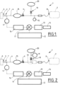
- Station 1 for filling pressurized fluid tanks shown schematically in figure 1 conventionally comprises a filling pipe 4 comprising at least one upstream end 3 connected to at least one source 5 of pressurized gas and at least one downstream end 8 intended to be connected to a tank 2 to be filled.
- the gas source (in particular hydrogen) may comprise at least one of: one or more pressurized gas tanks, in particular several tanks connected in parallel for cascade filling, a compressor, a source of liquefied gas and a vaporizer, and/or any other suitable pressurized gas source.
- the downstream end comprises, for example, at least one flexible pipe, the terminal end of which comprises a connector, preferably a quick connector, allowing its sealed connection with the inlet of a tank 2 or a filling circuit of a tank 2 (in particular of a vehicle).
- a connector preferably a quick connector
- the filling line 4 comprising a flow meter 9 and at least one downstream isolation valve 6 arranged between the flow meter and the downstream end 8 of the filling line 4.
- the isolation valve 6 is preferably a controlled valve 6 to allow a gas transfer step from the source 5 to the tank 2 when it is open.
- the flow meter 9 preferably of the Coriolis effect type, is configured to measure the quantity of gas transferred and generate a corresponding signal (preferably an electrical signal).
- the station 1 comprises an electronic device 12 for processing and storing data, comprising in particular a microprocessor or a computer.
- This electronic device 12 is configured to receive the signal from the flow meter 9 and to generate a signal of corrected quantity of transferred gas obtained by reducing or increasing by a determined corrective quantity the quantity of transferred gas measured by the flow meter 9 during the transfer.
- the electronic device 12 can be configured to control all or part of the valves 6, 10 or components of the station and/or to receive pressure and/or temperature measurements 15 in the filling circuit 4 (upstream and/or downstream of the downstream isolation valve 6).
- the electronic device 12 can be configured to control the transfer of gas to the tank (flow rate control and/or sources, etc.).
- the electronic device 12 may comprise or be associated with a human-machine interface comprising, for example, a display 13 and/or a payment and/or input or identification terminal 14.
- the electronic device 12 may comprise wireless communication means for transmitting or receiving these data or/or other data.
- all or part of the means for calculating and/or storing data and/or displaying and/or invoicing may be remote from the station 1 (via the Internet or a local network and using, for example, applications on a wireless telephone).
- the filling line 4 also preferably further comprises a purge valve 10 located downstream of the downstream isolation valve 6.
- the purge valve 10 is preferably controlled to discharge outside the filling line 4 at least a portion of the pressurized gas trapped in the downstream portion of the filling line 4 after a transfer step (at the end of a filling).
- the purged gas is discharged to the atmosphere or into a recovery zone 20.
- This corrective quantity is a fixed quantity or a percentage (fixed or variable) which is a function (which varies) according to the filling conditions and in particular the final pressure.
- the final pressure in the tank 2 or in the filling line 4 at the end of the transfer step is measured 15 (or estimated) and the corrective determined quantity is a quantity which varies as a function of this final pressure, in particular proportionally.
- the corrective determined quantity is a fixed quantity according to the interval of the final pressure at the end of the transfer step.
- the corrective determined quantity is a fixed quantity according to the pressure interval at the end of the transfer step and between 11 and 5 grams when the pressure in the tank to be filled or in the filling line 4 is between 850 and 700 bar and between 8 and 2.5 grams when the pressure in the tank 2 to be filled or in the filling line 4 is between 700 and 400 bar and between 6 and 1 gram when the pressure in the tank 2 to be filled or in the filling line 4 is between 400 and 200 bar.
- the determined corrective quantity of gas may possibly also vary depending on the temperature of the gas in the tank 2 to be filled or in the filling line 4.
- the determined corrective quantity of gas may possibly vary depending on the volume of tank 2 (known or measured) and/or the known or measured volume of filling circuit 4.
- the corrective determined quantity of gas may be the calculated or measured quantity of gas evacuated via the purge valve 10.
- the quantity of purged gas can be estimated from the known volume in the circuit 4 between the downstream isolation valve 6 and the downstream end 8, from the pressure 15 measured in this part of the circuit 4, from the temperature measured or estimated in this part of the circuit 4, from the characteristics of the gas (its nature, its molar mass, etc.), and from the final pressure in the pipe 4 after the transfer step and after the purge step.
- the density and/or the purged gas mass can be calculated.
- the corrective determined quantity of gas is calculated by a gas equation of state. For example this quantity is calculated via the ideal or real gas equation applied to the gas in the downstream part of the gas line.
- the corrective quantity may be the result of the difference between the calculated quantity of gas present in the downstream part of the filling line 4 before the purge step and the calculated quantity of gas present in the downstream part of the filling line 4 after the purge step.
- the station may comprise a second purge flow meter 11 located downstream of the purge valve 10 configured to measure the quantity of gas purged during the purge step.
- the determined corrective quantity of gas is for example the quantity of gas measured by the purge flow meter 11 or a determined fraction thereof.
- the generation of a corrected transferred gas quantity signal is obtained by subtracting or adding a determined quantity of gas to the quantity of transferred gas measured by the flow meter 9 during the transfer step.
- This correction can be carried out at the end of the transfer step and/or dynamically during the gas transfer (e.g. progressively).
- the flow meter 9 is of the type generating electrical signals in the form of successive pulses, each corresponding to an elementary quantity of gas measured. That is to say, each time the flow meter measures the passage of a quantity of gas (for example one gram), it emits a pulse.
- the flow rate corresponds to the number of pulses per unit of time (for example a certain number of grams per minute).
- the corrected transferred gas quantity signal can be obtained by subtracting or adding a determined quantity of pulses to the sum of pulses generated by the flow meter 9 during the transfer step.
- the electronic data processing and storage device 12 may comprise or be associated with a pulse counting member 16 and a pulse correction member 17. accounted for (this or these organs 16, 17 may include electronic cards or any other appropriate device).
- the filling circuit 4 may include other elements and in particular valve(s) 7 upstream or downstream of the downstream isolation valve 6 and/or a buffer volume between the flow meter 9 and the downstream isolation valve 6, a gas cooling exchanger 19 downstream of the downstream isolation valve 6, etc.
Landscapes
- Engineering & Computer Science (AREA)
- Physics & Mathematics (AREA)
- Fluid Mechanics (AREA)
- General Physics & Mathematics (AREA)
- Mechanical Engineering (AREA)
- General Engineering & Computer Science (AREA)
- Electromagnetism (AREA)
- Filling Or Discharging Of Gas Storage Vessels (AREA)
- Measuring Volume Flow (AREA)
Claims (10)
- Verfahren zum Messen der Gasmenge, die in einen Tank (2) für Gas über eine Füllstation (1) eingeführt wird, die mit einer Füllleitung (4) versehen ist, die ein stromaufwärtiges Ende (3), das mit mindestens einer Quelle (5) für Gas unter Druck verbunden ist, und ein stromabwärtiges Ende (8), das an einen zu befüllenden Tank (2) angeschlossen ist, umfasst, wobei die Füllleitung (4) einen Durchflussmesser (9) und mindestens ein stromabwärtiges Absperrventil (6), das zwischen dem Durchflussmesser und dem stromabwärtigen Ende (8) der Füllleitung angeordnet ist, umfasst, wobei das Verfahren einen Schritt des Transfers von Gas von der Quelle (5) zu einem Tank (2), während dessen das stromabwärtige Absperrventil (6) geöffnet ist, einen Schritt des Unterbrechens des Transfers von Gas mit einem Schließen des stromabwärtigen Ventils (6) umfasst, wobei das Verfahren einen Schritt des Messens, durch den Durchflussmesser (9), der während des Transferschritts transferierten Gasmenge umfasst, wobei das Verfahren einen Schritt des Erzeugens eines Signals für eine korrigierte Menge transferierten Gases umfasst, das erhalten wird, indem die während des Transferschritts von dem Durchflussmesser (9) gemessene Menge transferierten Gases um eine bestimmte korrigierende Menge vermindert oder erhöht wird, wobei das Verfahren einen Schritt umfasst, bei dem der finale Druck in dem Tank (2) oder in der Füllleitung (4) am Ende des Transferschritts gemessen oder geschätzt wird und die bestimmte korrigierende Menge eine Menge ist, die in Abhängigkeit von diesem finalen Druck variiert, und dadurch gekennzeichnet, dass die bestimmte korrigierende Menge eine feststehende vorbestimmte Menge gemäß dem Druckintervall am Ende des Transferschritts ist und zwischen 11 und 5 Gramm beträgt, wenn der Druck in dem zu befüllenden Tank oder in der Füllleitung (4) zwischen 850 und 700 bar beträgt, und zwischen 8 und 2,5 Gramm, wenn der Druck in dem zu befüllenden Tank (2) oder in der Füllleitung (4) zwischen 700 und 400 bar beträgt, und zwischen 6 und 1 Gramm, wenn der Druck in dem zu befüllenden Tank (2) oder in der Füllleitung (4) zwischen 400 und 200 bar beträgt.
- Verfahren nach Anspruch 1, dadurch gekennzeichnet, dass das Signal für die korrigierte Menge transferierten Gases gespeichert und/oder übertragen und/oder angezeigt wird.
- Verfahren nach einem der Ansprüche 1 oder 2, dadurch gekennzeichnet, dass das Signal für die korrigierte Menge transferierten Gases in einem Schritt des Berechnens einer Fakturierung der in den Tank (2) eingeführten Gasmenge verwendet wird.
- Verfahren nach einem der Ansprüche 1 bis 3, dadurch gekennzeichnet, dass die bestimmte korrigierende Gasmenge eine Menge ist, die in Abhängigkeit von der Temperatur des Gases in dem zu befüllenden Tank (2) oder in der Füllleitung (4) variiert.
- Verfahren nach einem der Ansprüche 1 bis 4, dadurch gekennzeichnet, dass die bestimmte korrigierende Gasmenge durch eine Gleichung idealer oder realer Gase berechnet wird, die auf das Gas in dem stromabwärtigen Teil der Füllleitung vor dem Entlüftungsschritt und nach dem Entlüftungsschritt ausgehend von den folgenden Parametern angewandt wird: bekanntes Volumen der Füllleitung stromab des stromabwärtigen Absperrventils (6), gemessener finaler Druck in dem zu befüllenden Tank (2) oder in der Füllleitung (4) am Ende des Transferschritts vor dem Entlüftungsschritt, gemessene oder geschätzte Temperatur des Gases in dem zu befüllenden Tank (2) oder in der Füllleitung (4), bekannte Art des Gases und insbesondere seine molare Masse, Druck in der Füllleitung (4) nach dem Entlüftungsschritt, und dadurch, dass die korrigierende Menge das Ergebnis der Differenz zwischen der berechneten Gasmenge, die in dem stromabwärtigen Teil der Füllleitung (4) vor dem Entlüftungsschritt vorhanden ist, und der berechneten Gasmenge, die in dem stromabwärtigen Teil der Füllleitung (4) nach dem Entlüftungsschritt vorhanden ist, ist.
- Verfahren nach Anspruch 5, dadurch gekennzeichnet, dass die Füllleitung (4) einen Entlüftungsdurchflussmesser (11) umfasst, der stromab des Entlüftungsventils (10) gelegen ist, um die bei dem Entlüftungsschritt entlüftete Gasmenge zu messen, und dass die bestimmte korrigierende Gasmenge die von dem Entlüftungsdurchflussmesser (11) gemessene Gasmenge oder ein bestimmter Anteil davon ist.
- Verfahren nach einem der vorhergehenden Ansprüche, dadurch gekennzeichnet, dass das Erzeugen eines Signals für die korrigierte transferierte Gasmenge erhalten wird, indem eine bestimmte Gasmenge von der von dem Durchflussmesser (9) während des Transferschritts gemessenen Menge transferierten Gases subtrahiert oder dazu addiert wird.
- Verfahren nach Anspruch 7, dadurch gekennzeichnet, dass der Durchflussmesser (9) von dem Typ ist, der elektrische Signale in Form von aufeinander folgenden Impulsen erzeugt, die jeweils einer gemessenen elementaren Gasmenge entsprechen, und dass das Erzeugen eines Signals für die korrigierte transferierte Gasmenge erhalten wird, indem eine bestimmte Menge von Impulsen von der Summe der von dem Durchflussmesser (9) während des Transferschritts erzeugten Impulsen subtrahiert oder dazu addiert wird.
- Verfahren nach einem der Ansprüche 1 bis 8, dadurch gekennzeichnet, dass die Füllstation (1) eine elektronische Vorrichtung (12) zur Verarbeitung und Speicherung von Daten umfasst, die insbesondere einen Mikroprozessor oder einen Computer umfasst, wobei die elektronische Vorrichtung (12) dazu ausgestaltet ist, ein Signal zu empfangen, das für die von dem Durchflussmesser (9) während des Transferschritts gemessene Menge transferierten Gases repräsentativ ist, und das Signal für die korrigierte Menge transferierten Gases zu berechnen und/oder zu empfangen und/oder zu übertragen und/oder anzuzeigen.
- Station zum Befüllen von Tanks mit Fluid unter Druck, insbesondere zum Befüllen von Tanks mit Wasserstoff unter Druck, die eine Füllleitung (4) aufweist, die ein stromaufwärtiges Ende (3), das mit mindestens einer Quelle (5) für Gas unter Druck verbunden ist, und mindestens ein stromabwärtiges Ende (8), das dazu bestimmt ist, an einen zu befüllenden Tank (2) angeschlossen zu werden, umfasst, wobei die Füllleitung (4) einen Durchflussmesser (9) umfasst und mindestens ein stromabwärtiges Absperrventil (6), das zwischen dem Durchflussmesser und dem stromabwärtigen Ende (8) der Füllleitung angeordnet ist, wobei das mindestens eine Ventil (6) angesteuert wird, um einen Schritt des Transfers von Gas von der Quelle (5) zu dem Tank (2) zu ermöglichen, wobei der Durchflussmesser (9) dazu ausgestaltet ist, die transferierte Gasmenge zu messen und ein entsprechendes Signal zu erzeugen, wobei die Station (1) eine elektronische Vorrichtung (12) zur Verarbeitung und Speicherung von Daten umfasst, die insbesondere einen Mikroprozessor oder einen Computer umfasst, wobei die elektronische Vorrichtung (12) dazu ausgestaltet ist, das Signal des Durchflussmessers zu empfangen und ein Signal für die korrigierte Menge transferierten Gases zu erzeugen, das erhalten wird, indem die von dem Durchflussmesser (9) während des Transfers gemessenen Menge transferierten Gases um eine bestimmte korrigierende Menge verringert oder erhöht wird, wobei der finale Druck in dem Tank (2) oder in der Füllleitung (4) am Ende des Transferschritts gemessen oder geschätzt wird, wobei die bestimmte korrigierende Menge eine Menge ist, die in Abhängigkeit von diesem finalen Druck variiert, insbesondere proportional, und dadurch gekennzeichnet, dass die bestimmte korrigierende Menge eine feststehende vorbestimmte Menge gemäß dem Druckintervall am Ende des Transferschritts ist und zwischen 11 und 5 Gramm beträgt, wenn der Druck in dem zu befüllenden Tank oder in der Füllleitung (4) zwischen 850 und 700 bar beträgt, und zwischen 8 und 2,5 Gramm, wenn der Druck in dem zu befüllenden Tank (2) oder in der Füllleitung (4) zwischen 700 und 400 bar beträgt, und zwischen 6 und 1 Gramm, wenn der Druck in dem zu befüllenden Tank (2) oder in der Füllleitung (4) zwischen 400 und 200 bar beträgt.
Applications Claiming Priority (2)
| Application Number | Priority Date | Filing Date | Title |
|---|---|---|---|
| FR1753045A FR3065068B1 (fr) | 2017-04-07 | 2017-04-07 | Procede pour mesurer la quantite de gaz introduite dans un reservoir et station de remplissage |
| PCT/FR2018/050774 WO2018185404A1 (fr) | 2017-04-07 | 2018-03-29 | Procédé pour mesurer la quantité de gaz introduite dans un réservoir et station de remplissage |
Publications (2)
| Publication Number | Publication Date |
|---|---|
| EP3607282A1 EP3607282A1 (de) | 2020-02-12 |
| EP3607282B1 true EP3607282B1 (de) | 2024-09-11 |
Family
ID=59253690
Family Applications (1)
| Application Number | Title | Priority Date | Filing Date |
|---|---|---|---|
| EP18718886.7A Active EP3607282B1 (de) | 2017-04-07 | 2018-03-29 | Verfahren zur messung der in ein reservoir und einer und füllstation eingeleiteten gasmenge |
Country Status (9)
| Country | Link |
|---|---|
| US (1) | US11162640B2 (de) |
| EP (1) | EP3607282B1 (de) |
| JP (1) | JP2020515784A (de) |
| KR (1) | KR20190137114A (de) |
| CN (1) | CN110462350A (de) |
| CA (1) | CA3059193A1 (de) |
| DK (1) | DK3607282T3 (de) |
| FR (1) | FR3065068B1 (de) |
| WO (1) | WO2018185404A1 (de) |
Families Citing this family (1)
| Publication number | Priority date | Publication date | Assignee | Title |
|---|---|---|---|---|
| KR102766164B1 (ko) * | 2022-08-29 | 2025-02-12 | 한국자동차연구원 | 수소 충전 보조장치 및 이를 구비한 수소 충전 시스템 |
Citations (4)
| Publication number | Priority date | Publication date | Assignee | Title |
|---|---|---|---|---|
| JP2004257525A (ja) * | 2003-02-27 | 2004-09-16 | Tokiko Techno Kk | ガス供給装置及びその制御方法 |
| JP2007024152A (ja) * | 2005-07-14 | 2007-02-01 | Tokiko Techno Kk | ガス供給装置 |
| US20090084194A1 (en) * | 2007-09-28 | 2009-04-02 | Robert Shock | Coriolis dosing system for filling gas cylinders |
| JP2014043882A (ja) * | 2012-08-27 | 2014-03-13 | Tatsuno Corp | ガス充填装置 |
Family Cites Families (9)
| Publication number | Priority date | Publication date | Assignee | Title |
|---|---|---|---|---|
| US5671785A (en) * | 1995-08-15 | 1997-09-30 | Dresser Industries, Inc. | Gasoline dispensing and vapor recovery system and method |
| JP2003336795A (ja) * | 2002-03-13 | 2003-11-28 | Nippon Sanso Corp | 燃料充填装置および燃料漏れ検出方法 |
| AU2003239621A1 (en) * | 2002-05-24 | 2003-12-12 | Mykrolis Corporation | System and method for mass flow detection device calibration |
| US6708573B1 (en) * | 2002-09-12 | 2004-03-23 | Air Products And Chemicals, Inc. | Process for filling compressed gas fuel dispensers which utilizes volume and density calculations |
| US20070186982A1 (en) * | 2006-02-10 | 2007-08-16 | Cohen Joseph P | Method for dispensing compressed gas |
| US9557744B2 (en) * | 2012-01-20 | 2017-01-31 | Mks Instruments, Inc. | System for and method of monitoring flow through mass flow controllers in real time |
| CN104215282B (zh) * | 2013-05-30 | 2017-10-27 | 中国石油化工股份有限公司 | 气体流量测定装置和使用该装置进行气体流量测定的方法 |
| CN104654007B (zh) * | 2015-03-16 | 2017-02-22 | 西北工业大学 | 一种乙烯供给装置及其流量测量方法 |
| JP6150839B2 (ja) * | 2015-04-14 | 2017-06-21 | 本田技研工業株式会社 | 燃料充填システム及びその燃料充填方法 |
-
2017
- 2017-04-07 FR FR1753045A patent/FR3065068B1/fr active Active
-
2018
- 2018-03-29 WO PCT/FR2018/050774 patent/WO2018185404A1/fr not_active Ceased
- 2018-03-29 US US16/603,376 patent/US11162640B2/en active Active
- 2018-03-29 EP EP18718886.7A patent/EP3607282B1/de active Active
- 2018-03-29 CN CN201880020369.5A patent/CN110462350A/zh active Pending
- 2018-03-29 DK DK18718886.7T patent/DK3607282T3/da active
- 2018-03-29 KR KR1020197032003A patent/KR20190137114A/ko not_active Abandoned
- 2018-03-29 JP JP2019552985A patent/JP2020515784A/ja not_active Ceased
- 2018-03-29 CA CA3059193A patent/CA3059193A1/fr active Pending
Patent Citations (4)
| Publication number | Priority date | Publication date | Assignee | Title |
|---|---|---|---|---|
| JP2004257525A (ja) * | 2003-02-27 | 2004-09-16 | Tokiko Techno Kk | ガス供給装置及びその制御方法 |
| JP2007024152A (ja) * | 2005-07-14 | 2007-02-01 | Tokiko Techno Kk | ガス供給装置 |
| US20090084194A1 (en) * | 2007-09-28 | 2009-04-02 | Robert Shock | Coriolis dosing system for filling gas cylinders |
| JP2014043882A (ja) * | 2012-08-27 | 2014-03-13 | Tatsuno Corp | ガス充填装置 |
Also Published As
| Publication number | Publication date |
|---|---|
| WO2018185404A1 (fr) | 2018-10-11 |
| JP2020515784A (ja) | 2020-05-28 |
| CA3059193A1 (fr) | 2018-10-11 |
| CN110462350A (zh) | 2019-11-15 |
| US11162640B2 (en) | 2021-11-02 |
| US20200032959A1 (en) | 2020-01-30 |
| FR3065068B1 (fr) | 2019-08-02 |
| FR3065068A1 (fr) | 2018-10-12 |
| EP3607282A1 (de) | 2020-02-12 |
| KR20190137114A (ko) | 2019-12-10 |
| DK3607282T3 (da) | 2024-11-18 |
Similar Documents
| Publication | Publication Date | Title |
|---|---|---|
| EP3607279B1 (de) | Verfahren zur messung der in einen tank eingetroffenen gasmenge und tankstelle | |
| EP3607280B1 (de) | Verfahren zur messung der in einen behälter eingeführten gasmenge und entsprechende füllstation | |
| EP1398603A2 (de) | Prozess zum Abfüllen von Verteilern mit komprimiertem gasförmigem Brennstoff unter Anwendung von Berechnungen von Volumen und Dichte | |
| FR2948438A1 (fr) | Procede d'estimation du volume d'un reservoir de gaz sous pression. | |
| WO2007077376A2 (fr) | Procede et dispositif de remplissage de conteneurs de gaz sous pression | |
| CN107941307A (zh) | 一种常规大型液体发动机推进剂流量现场校准系统及方法 | |
| EP3607282B1 (de) | Verfahren zur messung der in ein reservoir und einer und füllstation eingeleiteten gasmenge | |
| JP3988050B2 (ja) | ガス充填装置 | |
| EP3411624B1 (de) | Ausgabesystem für kryogene flüssigkeit | |
| CN106248160A (zh) | 燃油流量计的检测系统及检测方法 | |
| CN114252124B (zh) | 压缩气体存储容器容积计算方法、装置、计算机和介质 | |
| WO2024165392A1 (fr) | Ensemble comprenant un distributeur de fluide et un simulateur d'un réservoir à remplir, et utilisation d'un tel ensemble | |
| RU2625255C1 (ru) | Способ определения количества газа высокого давления, отпускаемого в приёмник потребителя | |
| FR2688881A1 (fr) | Dispositif de controle de l'exactitude de la mesure d'un volume de fluide. | |
| KR20210074950A (ko) | 차량용 주유량 측정기 | |
| KR20010011550A (ko) | 가스용기 충전소의 충전장치용 유량계 |
Legal Events
| Date | Code | Title | Description |
|---|---|---|---|
| STAA | Information on the status of an ep patent application or granted ep patent |
Free format text: STATUS: UNKNOWN |
|
| STAA | Information on the status of an ep patent application or granted ep patent |
Free format text: STATUS: THE INTERNATIONAL PUBLICATION HAS BEEN MADE |
|
| PUAI | Public reference made under article 153(3) epc to a published international application that has entered the european phase |
Free format text: ORIGINAL CODE: 0009012 |
|
| STAA | Information on the status of an ep patent application or granted ep patent |
Free format text: STATUS: REQUEST FOR EXAMINATION WAS MADE |
|
| 17P | Request for examination filed |
Effective date: 20191107 |
|
| AK | Designated contracting states |
Kind code of ref document: A1 Designated state(s): AL AT BE BG CH CY CZ DE DK EE ES FI FR GB GR HR HU IE IS IT LI LT LU LV MC MK MT NL NO PL PT RO RS SE SI SK SM TR |
|
| AX | Request for extension of the european patent |
Extension state: BA ME |
|
| DAV | Request for validation of the european patent (deleted) | ||
| DAX | Request for extension of the european patent (deleted) | ||
| STAA | Information on the status of an ep patent application or granted ep patent |
Free format text: STATUS: EXAMINATION IS IN PROGRESS |
|
| 17Q | First examination report despatched |
Effective date: 20211014 |
|
| RIC1 | Information provided on ipc code assigned before grant |
Ipc: F17C 5/06 20060101ALI20240306BHEP Ipc: G01F 15/00 20060101ALI20240306BHEP Ipc: G01F 13/00 20060101ALI20240306BHEP Ipc: G01F 22/02 20060101AFI20240306BHEP |
|
| GRAP | Despatch of communication of intention to grant a patent |
Free format text: ORIGINAL CODE: EPIDOSNIGR1 |
|
| STAA | Information on the status of an ep patent application or granted ep patent |
Free format text: STATUS: GRANT OF PATENT IS INTENDED |
|
| GRAJ | Information related to disapproval of communication of intention to grant by the applicant or resumption of examination proceedings by the epo deleted |
Free format text: ORIGINAL CODE: EPIDOSDIGR1 |
|
| STAA | Information on the status of an ep patent application or granted ep patent |
Free format text: STATUS: EXAMINATION IS IN PROGRESS |
|
| GRAP | Despatch of communication of intention to grant a patent |
Free format text: ORIGINAL CODE: EPIDOSNIGR1 |
|
| STAA | Information on the status of an ep patent application or granted ep patent |
Free format text: STATUS: GRANT OF PATENT IS INTENDED |
|
| INTG | Intention to grant announced |
Effective date: 20240419 |
|
| INTC | Intention to grant announced (deleted) | ||
| INTG | Intention to grant announced |
Effective date: 20240513 |
|
| GRAS | Grant fee paid |
Free format text: ORIGINAL CODE: EPIDOSNIGR3 |
|
| GRAA | (expected) grant |
Free format text: ORIGINAL CODE: 0009210 |
|
| STAA | Information on the status of an ep patent application or granted ep patent |
Free format text: STATUS: THE PATENT HAS BEEN GRANTED |
|
| AK | Designated contracting states |
Kind code of ref document: B1 Designated state(s): AL AT BE BG CH CY CZ DE DK EE ES FI FR GB GR HR HU IE IS IT LI LT LU LV MC MK MT NL NO PL PT RO RS SE SI SK SM TR |
|
| REG | Reference to a national code |
Ref country code: GB Ref legal event code: FG4D Free format text: NOT ENGLISH |
|
| REG | Reference to a national code |
Ref country code: CH Ref legal event code: EP |
|
| REG | Reference to a national code |
Ref country code: DE Ref legal event code: R096 Ref document number: 602018074221 Country of ref document: DE |
|
| REG | Reference to a national code |
Ref country code: IE Ref legal event code: FG4D Free format text: LANGUAGE OF EP DOCUMENT: FRENCH |
|
| REG | Reference to a national code |
Ref country code: DK Ref legal event code: T3 Effective date: 20241114 |
|
| REG | Reference to a national code |
Ref country code: NL Ref legal event code: FP |
|
| REG | Reference to a national code |
Ref country code: LT Ref legal event code: MG9D |
|
| PG25 | Lapsed in a contracting state [announced via postgrant information from national office to epo] |
Ref country code: NO Free format text: LAPSE BECAUSE OF FAILURE TO SUBMIT A TRANSLATION OF THE DESCRIPTION OR TO PAY THE FEE WITHIN THE PRESCRIBED TIME-LIMIT Effective date: 20241211 |
|
| PG25 | Lapsed in a contracting state [announced via postgrant information from national office to epo] |
Ref country code: GR Free format text: LAPSE BECAUSE OF FAILURE TO SUBMIT A TRANSLATION OF THE DESCRIPTION OR TO PAY THE FEE WITHIN THE PRESCRIBED TIME-LIMIT Effective date: 20241212 Ref country code: FI Free format text: LAPSE BECAUSE OF FAILURE TO SUBMIT A TRANSLATION OF THE DESCRIPTION OR TO PAY THE FEE WITHIN THE PRESCRIBED TIME-LIMIT Effective date: 20240911 |
|
| PG25 | Lapsed in a contracting state [announced via postgrant information from national office to epo] |
Ref country code: BG Free format text: LAPSE BECAUSE OF FAILURE TO SUBMIT A TRANSLATION OF THE DESCRIPTION OR TO PAY THE FEE WITHIN THE PRESCRIBED TIME-LIMIT Effective date: 20240911 |
|
| PG25 | Lapsed in a contracting state [announced via postgrant information from national office to epo] |
Ref country code: LV Free format text: LAPSE BECAUSE OF FAILURE TO SUBMIT A TRANSLATION OF THE DESCRIPTION OR TO PAY THE FEE WITHIN THE PRESCRIBED TIME-LIMIT Effective date: 20240911 |
|
| PG25 | Lapsed in a contracting state [announced via postgrant information from national office to epo] |
Ref country code: HR Free format text: LAPSE BECAUSE OF FAILURE TO SUBMIT A TRANSLATION OF THE DESCRIPTION OR TO PAY THE FEE WITHIN THE PRESCRIBED TIME-LIMIT Effective date: 20240911 |
|
| PG25 | Lapsed in a contracting state [announced via postgrant information from national office to epo] |
Ref country code: ES Free format text: LAPSE BECAUSE OF FAILURE TO SUBMIT A TRANSLATION OF THE DESCRIPTION OR TO PAY THE FEE WITHIN THE PRESCRIBED TIME-LIMIT Effective date: 20240911 Ref country code: RS Free format text: LAPSE BECAUSE OF FAILURE TO SUBMIT A TRANSLATION OF THE DESCRIPTION OR TO PAY THE FEE WITHIN THE PRESCRIBED TIME-LIMIT Effective date: 20241211 |
|
| PG25 | Lapsed in a contracting state [announced via postgrant information from national office to epo] |
Ref country code: RS Free format text: LAPSE BECAUSE OF FAILURE TO SUBMIT A TRANSLATION OF THE DESCRIPTION OR TO PAY THE FEE WITHIN THE PRESCRIBED TIME-LIMIT Effective date: 20241211 Ref country code: NO Free format text: LAPSE BECAUSE OF FAILURE TO SUBMIT A TRANSLATION OF THE DESCRIPTION OR TO PAY THE FEE WITHIN THE PRESCRIBED TIME-LIMIT Effective date: 20241211 Ref country code: LV Free format text: LAPSE BECAUSE OF FAILURE TO SUBMIT A TRANSLATION OF THE DESCRIPTION OR TO PAY THE FEE WITHIN THE PRESCRIBED TIME-LIMIT Effective date: 20240911 Ref country code: HR Free format text: LAPSE BECAUSE OF FAILURE TO SUBMIT A TRANSLATION OF THE DESCRIPTION OR TO PAY THE FEE WITHIN THE PRESCRIBED TIME-LIMIT Effective date: 20240911 Ref country code: GR Free format text: LAPSE BECAUSE OF FAILURE TO SUBMIT A TRANSLATION OF THE DESCRIPTION OR TO PAY THE FEE WITHIN THE PRESCRIBED TIME-LIMIT Effective date: 20241212 Ref country code: FI Free format text: LAPSE BECAUSE OF FAILURE TO SUBMIT A TRANSLATION OF THE DESCRIPTION OR TO PAY THE FEE WITHIN THE PRESCRIBED TIME-LIMIT Effective date: 20240911 Ref country code: ES Free format text: LAPSE BECAUSE OF FAILURE TO SUBMIT A TRANSLATION OF THE DESCRIPTION OR TO PAY THE FEE WITHIN THE PRESCRIBED TIME-LIMIT Effective date: 20240911 Ref country code: BG Free format text: LAPSE BECAUSE OF FAILURE TO SUBMIT A TRANSLATION OF THE DESCRIPTION OR TO PAY THE FEE WITHIN THE PRESCRIBED TIME-LIMIT Effective date: 20240911 |
|
| REG | Reference to a national code |
Ref country code: AT Ref legal event code: MK05 Ref document number: 1723079 Country of ref document: AT Kind code of ref document: T Effective date: 20240911 |
|
| PG25 | Lapsed in a contracting state [announced via postgrant information from national office to epo] |
Ref country code: IS Free format text: LAPSE BECAUSE OF FAILURE TO SUBMIT A TRANSLATION OF THE DESCRIPTION OR TO PAY THE FEE WITHIN THE PRESCRIBED TIME-LIMIT Effective date: 20250111 Ref country code: PT Free format text: LAPSE BECAUSE OF FAILURE TO SUBMIT A TRANSLATION OF THE DESCRIPTION OR TO PAY THE FEE WITHIN THE PRESCRIBED TIME-LIMIT Effective date: 20250113 |
|
| PG25 | Lapsed in a contracting state [announced via postgrant information from national office to epo] |
Ref country code: RO Free format text: LAPSE BECAUSE OF FAILURE TO SUBMIT A TRANSLATION OF THE DESCRIPTION OR TO PAY THE FEE WITHIN THE PRESCRIBED TIME-LIMIT Effective date: 20240911 Ref country code: SM Free format text: LAPSE BECAUSE OF FAILURE TO SUBMIT A TRANSLATION OF THE DESCRIPTION OR TO PAY THE FEE WITHIN THE PRESCRIBED TIME-LIMIT Effective date: 20240911 |
|
| PG25 | Lapsed in a contracting state [announced via postgrant information from national office to epo] |
Ref country code: EE Free format text: LAPSE BECAUSE OF FAILURE TO SUBMIT A TRANSLATION OF THE DESCRIPTION OR TO PAY THE FEE WITHIN THE PRESCRIBED TIME-LIMIT Effective date: 20240911 Ref country code: AT Free format text: LAPSE BECAUSE OF FAILURE TO SUBMIT A TRANSLATION OF THE DESCRIPTION OR TO PAY THE FEE WITHIN THE PRESCRIBED TIME-LIMIT Effective date: 20240911 |
|
| PG25 | Lapsed in a contracting state [announced via postgrant information from national office to epo] |
Ref country code: CZ Free format text: LAPSE BECAUSE OF FAILURE TO SUBMIT A TRANSLATION OF THE DESCRIPTION OR TO PAY THE FEE WITHIN THE PRESCRIBED TIME-LIMIT Effective date: 20240911 Ref country code: PL Free format text: LAPSE BECAUSE OF FAILURE TO SUBMIT A TRANSLATION OF THE DESCRIPTION OR TO PAY THE FEE WITHIN THE PRESCRIBED TIME-LIMIT Effective date: 20240911 |
|
| PG25 | Lapsed in a contracting state [announced via postgrant information from national office to epo] |
Ref country code: IT Free format text: LAPSE BECAUSE OF FAILURE TO SUBMIT A TRANSLATION OF THE DESCRIPTION OR TO PAY THE FEE WITHIN THE PRESCRIBED TIME-LIMIT Effective date: 20240911 Ref country code: SK Free format text: LAPSE BECAUSE OF FAILURE TO SUBMIT A TRANSLATION OF THE DESCRIPTION OR TO PAY THE FEE WITHIN THE PRESCRIBED TIME-LIMIT Effective date: 20240911 |
|
| REG | Reference to a national code |
Ref country code: DE Ref legal event code: R097 Ref document number: 602018074221 Country of ref document: DE |
|
| PLBE | No opposition filed within time limit |
Free format text: ORIGINAL CODE: 0009261 |
|
| STAA | Information on the status of an ep patent application or granted ep patent |
Free format text: STATUS: NO OPPOSITION FILED WITHIN TIME LIMIT |
|
| 26N | No opposition filed |
Effective date: 20250612 |
|
| PG25 | Lapsed in a contracting state [announced via postgrant information from national office to epo] |
Ref country code: SE Free format text: LAPSE BECAUSE OF FAILURE TO SUBMIT A TRANSLATION OF THE DESCRIPTION OR TO PAY THE FEE WITHIN THE PRESCRIBED TIME-LIMIT Effective date: 20240911 |
|
| REG | Reference to a national code |
Ref country code: DE Ref legal event code: R119 Ref document number: 602018074221 Country of ref document: DE |
|
| PG25 | Lapsed in a contracting state [announced via postgrant information from national office to epo] |
Ref country code: MC Free format text: LAPSE BECAUSE OF FAILURE TO SUBMIT A TRANSLATION OF THE DESCRIPTION OR TO PAY THE FEE WITHIN THE PRESCRIBED TIME-LIMIT Effective date: 20240911 |
|
| REG | Reference to a national code |
Ref country code: CH Ref legal event code: H13 Free format text: ST27 STATUS EVENT CODE: U-0-0-H10-H13 (AS PROVIDED BY THE NATIONAL OFFICE) Effective date: 20251024 |
|
| REG | Reference to a national code |
Ref country code: DK Ref legal event code: EBP Effective date: 20250331 |
|
| REG | Reference to a national code |
Ref country code: NL Ref legal event code: MM Effective date: 20250401 |
|
| PG25 | Lapsed in a contracting state [announced via postgrant information from national office to epo] |
Ref country code: LU Free format text: LAPSE BECAUSE OF NON-PAYMENT OF DUE FEES Effective date: 20250329 |
|
| GBPC | Gb: european patent ceased through non-payment of renewal fee |
Effective date: 20250329 |
|
| REG | Reference to a national code |
Ref country code: BE Ref legal event code: MM Effective date: 20250331 |
|
| PG25 | Lapsed in a contracting state [announced via postgrant information from national office to epo] |
Ref country code: NL Free format text: LAPSE BECAUSE OF NON-PAYMENT OF DUE FEES Effective date: 20250401 |
|
| PG25 | Lapsed in a contracting state [announced via postgrant information from national office to epo] |
Ref country code: DE Free format text: LAPSE BECAUSE OF NON-PAYMENT OF DUE FEES Effective date: 20251001 |
|
| PG25 | Lapsed in a contracting state [announced via postgrant information from national office to epo] |
Ref country code: GB Free format text: LAPSE BECAUSE OF NON-PAYMENT OF DUE FEES Effective date: 20250329 |
|
| PG25 | Lapsed in a contracting state [announced via postgrant information from national office to epo] |
Ref country code: FR Free format text: LAPSE BECAUSE OF NON-PAYMENT OF DUE FEES Effective date: 20250331 |
|
| PG25 | Lapsed in a contracting state [announced via postgrant information from national office to epo] |
Ref country code: BE Free format text: LAPSE BECAUSE OF NON-PAYMENT OF DUE FEES Effective date: 20250331 |
|
| PG25 | Lapsed in a contracting state [announced via postgrant information from national office to epo] |
Ref country code: CH Free format text: LAPSE BECAUSE OF NON-PAYMENT OF DUE FEES Effective date: 20250331 |
|
| PG25 | Lapsed in a contracting state [announced via postgrant information from national office to epo] |
Ref country code: IE Free format text: LAPSE BECAUSE OF NON-PAYMENT OF DUE FEES Effective date: 20250329 |
|
| PG25 | Lapsed in a contracting state [announced via postgrant information from national office to epo] |
Ref country code: DK Free format text: LAPSE BECAUSE OF NON-PAYMENT OF DUE FEES Effective date: 20250331 |