EP3607151B1 - Trennwandsystem - Google Patents
Trennwandsystem Download PDFInfo
- Publication number
- EP3607151B1 EP3607151B1 EP18721145.3A EP18721145A EP3607151B1 EP 3607151 B1 EP3607151 B1 EP 3607151B1 EP 18721145 A EP18721145 A EP 18721145A EP 3607151 B1 EP3607151 B1 EP 3607151B1
- Authority
- EP
- European Patent Office
- Prior art keywords
- door
- floor
- longitudinal profile
- defining
- fixed
- Prior art date
- Legal status (The legal status is an assumption and is not a legal conclusion. Google has not performed a legal analysis and makes no representation as to the accuracy of the status listed.)
- Active
Links
Images


Classifications
-
- E—FIXED CONSTRUCTIONS
- E04—BUILDING
- E04B—GENERAL BUILDING CONSTRUCTIONS; WALLS, e.g. PARTITIONS; ROOFS; FLOORS; CEILINGS; INSULATION OR OTHER PROTECTION OF BUILDINGS
- E04B2/00—Walls, e.g. partitions, for buildings; Wall construction with regard to insulation; Connections specially adapted to walls
- E04B2/74—Removable non-load-bearing partitions; Partitions with a free upper edge
- E04B2/7401—Removable non-load-bearing partitions; Partitions with a free upper edge assembled using panels without a frame or supporting posts, with or without upper or lower edge locating rails
-
- E—FIXED CONSTRUCTIONS
- E04—BUILDING
- E04B—GENERAL BUILDING CONSTRUCTIONS; WALLS, e.g. PARTITIONS; ROOFS; FLOORS; CEILINGS; INSULATION OR OTHER PROTECTION OF BUILDINGS
- E04B2/00—Walls, e.g. partitions, for buildings; Wall construction with regard to insulation; Connections specially adapted to walls
- E04B2/74—Removable non-load-bearing partitions; Partitions with a free upper edge
- E04B2/7407—Removable non-load-bearing partitions; Partitions with a free upper edge assembled using frames with infill panels or coverings only; made-up of panels and a support structure incorporating posts
- E04B2/7448—Removable non-load-bearing partitions; Partitions with a free upper edge assembled using frames with infill panels or coverings only; made-up of panels and a support structure incorporating posts with separate framed panels without intermediary posts, extending from floor to ceiling
- E04B2/745—Glazing details
-
- E—FIXED CONSTRUCTIONS
- E04—BUILDING
- E04B—GENERAL BUILDING CONSTRUCTIONS; WALLS, e.g. PARTITIONS; ROOFS; FLOORS; CEILINGS; INSULATION OR OTHER PROTECTION OF BUILDINGS
- E04B2/00—Walls, e.g. partitions, for buildings; Wall construction with regard to insulation; Connections specially adapted to walls
- E04B2/74—Removable non-load-bearing partitions; Partitions with a free upper edge
- E04B2002/749—Partitions with screw-type jacks
- E04B2002/7492—Partitions with screw-type jacks used in partitions extending from floor to ceiling
Definitions
- the present invention is generally applicable to the field of interior decoration, and it particularly relates to a system for partitioning an environment, especially for the so-called "open spaces" offices.
- Such systems are known for the realization of partitions of an environment, for example a so-called "open space” office.
- Such systems generally include a plurality of load-bearing beams and a plurality of partitioning walls inserted therein.
- open space offices are generally partitioned by means of glass walls and / or doors and are characterized by a high aesthetic appeal.
- the known systems provide for the realization of special beams and / or frames both on the top and laterally that are, therefore, not very pleasing at the sight, thus compromising the aesthetic appeal thereof.
- the beams and / or frames are realized ad hoc and, therefore, they have different sizes and configurations depending on the size of the environment, on the presence of the false ceiling, on the type of the partitioning wall and / or on the presence of a door.
- a further drawback of such systems is that the fixed walls and the doors are not aligned, thus compromising the aesthetic appeal of the whole system.
- Object of the present invention is to at least partially overcome the above mentioned drawbacks, by providing a partitioning system by means of at least one partition wall of an environment having high functionality and low cost.
- a further object of the invention is to provide a partitioning system apt to small variations of the environment wherein it is installed.
- Another object of the invention is to provide a partitioning system that is simple and fast to install.
- a further object of the invention is to provide a partitioning system of high aesthetic appeal.
- a further object of the invention is to provide a partitioning system that comprises both fixed walls and doors.
- a partitioning system 1 is described for an environment S that includes a ceiling C that defines a plane ⁇ and a floor F substantially faced to the ceiling C.
- the environment S may further include a false ceiling FC and / or a false floor FF that may be coupled respectively to the ceiling C and the floor F in a per se known manner or as described hereinafter.
- the partitioning system 1 according to the invention may be particularly suitable for open space environments that require a particularly attractive aesthetic appearance, such as offices or museums.
- the environment S is partitioned into at least two compartments V1 , V2 .
- the system 1 comprises at least one partition wall 10 that is placed in a plane ⁇ ' substantially perpendicular to the plane ⁇ .
- the partition wall 10 is formed by dividing planar elements, such as for example fixed walls 20, 30 and doors 40.
- Each fixed wall 20, 30 may extend substantially from the floor F or false floor FF to the ceiling C or false ceiling FC so as to give the system 1 a pleasing appearance to the eye.
- the present text describes substantially transparent fixed walls 20, 30 and doors 40, that is, comprising glass plates.
- the fixed wall 20 comprises at least one pair of glass plates 21, 22 ( Fig. 6 ) reciprocally facing to define a multilayer fixed wall 20.
- several fixed walls 20, 30 may be provided, each one may comprise a pair of glass plates 21, 22, 31, 32.
- the system 1 further comprises a door 40, wherein the door 40 comprises a pair of glass plates 41, 42, facing to define a multilayer door 40.
- the door 40 may extend substantially from the floor F or from the false floor FF to the ceiling C or false ceiling FC.
- a partition wall 10 is shown extending from a false floor FF that may be realized in a per se manner known. Possibly, the false floor FF and the floor F may have a variable reciprocal distance, that may be adjusted by means of known adjustment means.
- the fixed walls 20 , 30 and the door 40 are placed side by side therebetween to define the partition wall 10.
- the latter therefore, comprises an outer surface 11 facing the compartment V1 and the opposite outer surface 12 facing the compartment V2.
- the outer faces 28, 38, 48 and the opposite outer faces 29, 39, 49 respectively of the fixed walls 20, 30 and of the door 40 cooperate to define respectively the outer surface 11 and the opposite outer surface 12 of the partition wall 10.
- the glass plates 21, 41, 31 and 22, 42, 32 are present, the latter define the respective faces 28, 48, 38 and faces 29, 49, 39 respectively of the fixed wall 20, of the door 40 and of the fixed wall 30.
- the outer surface 11 is defined by the glass plates 21, 31, 41, while the outer surface 12 is defined by the opposite glass plates 22, 32, 42.
- the door 40 and the fixed walls 20, 30 are reciprocally configured so as once the door 40 is closed, the partition wall 10 has substantially continuous outer surfaces 11, 12, as better explained hereinafter.
- the door 40 and the fixed walls 20, 30 may have substantially the same thickness w so as the entire partition wall 10 has such a thickness.
- such a thickness w may be of 60 mm to 70 mm, preferably it may be of about 64 mm or of about 68 mm depending on the thickness of the glass plates used.
- the system 1 may comprise one or more longitudinal elements to laterally block the partition wall 10.
- the fixed walls 20, 30 and the door 40 may be laterally blocked in a upper and / or lower and / or side position.
- the system 1 comprises one or more upper longitudinal profiles 50 that are configured to block and / or act as abutment for one or more dividing planar elements.
- an upper longitudinal profile 50 thereof blocks the respective upper portion 20', 30' of the fixed walls 20, 30 and act as abutment for the upper portion 44 of the door 40 that may be placed side by side and interposed between the fixed walls 20, 30.
- partition wall 10 may be realized with any dividing planar element.
- the partition wall 10 may comprise several doors 40 and / or may comprise one or more fixed walls 20, 30 arranged at will.
- the upper profile 50 may have the same shape whether it is intended to block the fixed walls 20, 30 and to act as abutment for the door 40.
- the upper profile 50 may have a particularly reduced height, for example it may be about 50 mm.
- the system comprises an accessory 60 interposed between the upper profile 50 and the fixed part 20, 30 and the door 40 to couple the former with the latter.
- the accessory 60 is selectively engageable with the upper profile 50, preferably in a removable manner, so as to allow the assembly and disassembly of the partition wall 10 or of some dividing elements thereof.
- the upper profile 50 comprises a substantially planar area 51 intended to couple with the ceiling C and a pair of side walls 52 facing each other substantially perpendicular to the planar area 51.
- the upper profile 50 has a substantially "C” section so as the planar area 51 and the facing side walls 52 define a longitudinal seat 53 that at least partially houses the accessory 60.
- the upper profile 50 may remain visible ( Fig. 5 ) or it may be recessed ( Fig. 6 ), for example it may remain substantially flush with the false ceiling FC.
- a plurality of panels or of plasterboard sheets P may be selectively coupled with the upper profile 50 to realize such a false ceiling FC so as to selectively allow or conceal from the view of a user said at least one first upper longitudinal profile.
- the system 1 may comprise at least one pair of longitudinal support elements 70 that may be selectively coupled with the side walls 52 to couple with the panels or plasterboard sheets P to support the latter.
- the upper profile 50 may comprise a seat 54, preferably a pair of seats 54, to engage with a respective engagement portion 71 of the support element 70.
- the side walls 52 may comprise an end 55 facing the ceiling C, an opposite end 56 and a substantially planar portion 57 interposed between the ends 55, 56.
- the end 55 may be slightly spaced apart from the ceiling C so as between the end thereof and the planar area 51 a step 54 is formed defining the seat 54 for the support element 70.
- an upper profile 50 may comprise a pair of steps 54 placed on opposite sides with respect to the planar area 51.
- the distance between the end 55 and the ceiling C may define the height h1 of the step 54.
- Such an height h1 may be lower than 15 mm, preferably about 10 mm.
- the system 1 may have a pleasant appearance.
- the support element 70 may comprise a substantially horizontal portion 71 snap engaged in the seat 54, a substantially vertical portion 72 perpendicular to the portion 71 to interact with the substantially planar portion 57 and a portion 73 intended to interact with the panels P of the false ceiling FC to support the latter.
- the portion 73 may be substantially horizontal and it may remain substantially flush with the end 56 of the wall 52 so as the false ceiling FC is substantially flush with the upper profile 50.
- the false ceiling FC may be realized by means of plasterboard sheets P that may be plastered and shaved in order to be aligned with the upper profile 50.
- the portion 73 may comprise a plurality of projections 73' to couple the plasterboard sheets P to the portion 73 thereof by a per se known plastering.
- the portion 73 may be shaped in such a way that once the plasterboard sheet P is coupled therewith, the plasterboard sheet P remains substantially aligned with the end 56 of the wall 52.
- a shaving operation may be accomplished so as the false ceiling FC remains flush with the end 56 of the wall 52, that is, with the upper profile 50.
- the portion 73 may have a height substantially equal to the length of the walls 52.
- plasterboard sheets P may be coupled at different heights and not necessarily aligned with the end 56 of the wall 52 and / or plasterboard sheets P of different heights and / or a pair of overlapping plasterboard sheets P.
- such a feature may be particularly useful if it is necessary to realize false ceilings FC having different features or different heights from the floor F or false floor FF.
- plasterboard sheet P is absent, it is possible in any case to plaster and shave the projections 73' so as the portion 73 is substantially continuous and conceals the upper profile 50 from the sight.
- the system 1 may have a particularly pleasing appearance and, at the same time,it may be particularly adaptable.
- the assembly comprising the upper profile 50 and the pair of support elements 70 may have a lateral bulkiness of lower than 80 mm, of about 75-77 mm, that may, therefore, define the whole thickness of the system 1.
- the fixed walls 20, 30 and the door 40 may be coupled with the upper profile 50 whether the latter is visible or concealed by the false ceiling CF.
- a shaped accessory 60 may be provided to couple the fixed walls 20, 30 with the upper profile 50 and a shaped accessory 63 to couple the door 40 with the upper profile 50.
- the accessory 60 may remain completely inserted in the seat 53 so as not to be visible from the outside.
- the accessory 60 may comprise one or two seats 61 to respectively house the glass plate 21, 31 or both glass plates 21, 31 and 22, 32.
- the accessory 60 may comprise a pair of walls 62 cooperating with walls 52 to define such seats 61.
- a suitable shaped covering element 68 may be provided so as once coupled with the accessory 60, the covering element 68 may conceal one or both seats 61 from the sight.
- the glass plates 21, 31 and 22, 32 may only partially occupy the seats 61 so as to slide therein along an axis Y substantially perpendicular to the axis X.
- the latter may snap engage in a removable way with the upper profile 50.
- the glass plate 21, 31 and 22, 32 may remain visible up to the upper profile 50 and, if present, up to the false ceiling FC, so as the system 1 has a particularly pleasing appearance.
- the upper profile 50 and the walls 20, 30 may have substantially the same thickness, preferably the same thickness w of the partition wall 10.
- the walls 20, 30 comprise a single plate 21 31, as shown in Fig. 5 , the latter may remain substantially flush with one of the side walls 52 of the upper profile 50 so as to define a continuous face.
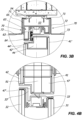
- the accessory 63 may be at least partially inserted in the seat 53 to abut against the door 40. Possibly, the accessory 63 may be telescopically inserted in the seat 53.
- the door 40 may comprise a frame 43 interposed between the glass plates 41, 42, that may comprise an upper portion 44 having a surface 44' susceptible to abut against a corresponding abutment surface 64 of the accessory 63 when the door 40 is closed.
- the upper profile 50, the accessory 63 and the door 40 may all have the same thickness so as once the door 40 is closed, the upper profile 50 and the door 40 thereof may be substantially continuous.
- a thickness may be equal to the thickness w of the partition wall 10.
- the plates 41, 42 may have different heights. As particularly shown in Fig. 3B , the plate 41 may have a height such that one of the upper ends 41' thereof is near the end 56 of the side wall 52, while the plate 42 may have a height such that one of the upper end 42' thereof is slightly spaced apart from the corresponding side wall 52.
- the space between the glass plates 41, 42 and the accessory 63 may be particularly reduced, so as to define a substantially continuous surface.
- the upper portion 44 of the frame 43 may have a step comprising the abutment surface 44', while the accessory 63 may have a corresponding step comprising the abutment surface 64.
- the surfaces 44' and 64 may be substantially parallel to the plane ⁇ ' .
- the accessory 63 may only partially occupy the longitudinal seat 53 so as to slide therein.
- the accessory 63 may comprise a pair of side faces 65 susceptible to come in contact with the side walls 52 of the upper profile 50, and an upper wall 66 that may be faced to the planar area 51 of the upper profile 50 thereof and spaced therefrom.
- the system 1 may adapt in case of small variation of the distance of the floor F or false floor FF from the ceiling C or false ceiling FC.
- accessory 63 may consist of one or more pieces without thereby departing from the scope of protection of the present invention.
- the partition wall 10 may have a predetermined distance h from the floor F or false floor FF.
- the door 40 and the fixed walls 20, 30 may have the same predetermined distance h so as to give the partition wall 10 a "floating" effect on the floor F or false floor FF and, more generally, so as to give a particularly pleasant appereance to the system 1.
- Such a predetermined distance may be particularly reduced, for example lower than 15 mm, preferably it may be about 10 mm.
- a lower profile 80 may be provided to support lower portions 20", 30" of the fixed walls 20, 30 and, in particular, the glass plates 21, 22, 31, 32 of the latter.
- the lower longitudinal profile 80 may be placed in correspondence to the upper profile 50 and it may define an axis X' thatmay be substantially parallel to the axis X.
- the lower profile 80 may comprise a pair of support surfaces 81 substantially parallel to the plane ⁇ to support the glass plates 21, 22, 31, 32 so as the latter remain entirely at sight.
- such support walls 81 may have a distance from the floor F or false floor FF substantially equal to the predetermined distance h.
- means 85 may be provided to move the lower profile 80 of a per se known type.
- the lower profile 80 may be movable to slightly vary the distance between the support walls 81 and the floor F or false floor FF so as to adapt to variations of the latter so as the glass plates 21, 22, 31, 32 have the same distance h from the floor F or false floor FF substantially throughout all the partition wall 10.
- the lower profile 80 may be suitable both for walls comprising a single glass plate 21, 31 ( Fig. 5 ) or a pair of glass plates 21, 22, 31, 32 ( Fig. 6 ).
- the user may place the fixed walls 20, 30 with the respective lower portions 20", 30" aligned along a line substantially parallel to the floor F or false floor FF so as to create the "floating"effect Suitably, such a line may remain at a predetermined distance h from the floor F or false floor FF.
- the frame 44 of the former may comprise a lower portion 45 interposed between the plates 41, 42 that may comprise respective side walls 45' to support the plates 41, 42.
- the lower portion 45 of the frame 44 may be spaced from the floor F or false floor FF to allow the movement of the door 40.
- the latter may be rotatably coupled with one of the fixed walls 20 and it may abut against the other fixed wall 30.
- the door 40 may be placed at such a distance h from the floor F or false floor FF so as the respective lower portion 45 of the door 40 is aligned along the same line at the predetermined distance h from the floor F or false floor FF.
- the fixed walls 20, 30 and the door 40 adapt to variations of the environment S even if presenting below such a predetermined distance h from the floor F or false floor FF and above a visual continuity with the upper profile 50 so as to give a pleasing aesthetic appearance.
- the door 40 may comprise a pair of vertical uprights 46, 47. More in detail, the frame 44 may comprise a pair of side portions 46, 47 defining said uprights, while the side walls 20, 30 may comprise a respective vertical longitudinal profile 23, 33 or upright, that, therefore, may be substantially perpendicular to the axes X, X' and to the plane ⁇ .
- the upright 23 may act as a rotation support for the door 40, while the upright 33 may be configured to abut against the door 40 when the latter is closed.
- the uprights 23, 33 may be interposed between the respective plates 21, 22 and 31, 32 and may have a particularly reduced thickness, for example lower than 15 mm, so as not to compromise the aesthetic appearance of the partition wall 10.
- the side profile 46 may be rotatably coupled with the upright 23, while the side profile 47 may abut against the upright 33.
- the door 40 may be rotatably fastened to the upright 23 by means of systems of a known type, for example a hinge for glass doors.
- the side portion 47 may comprise an abutment surface 47' susceptible to abut against a corresponding abutment surface 33' of the upright 33.
- elastomeric elements may be provided between the abutment surfaces 64 and 44' and / or between the abutment surfaces 33' and 47'.
- the upper profile 44 and the side profile 47, or, the upper profile 44, the side profile 47 and the side profile 46 may have a substantially identical shape.
- the accessory 63 and the upright 33, or the accessory 63, the upright 33 and the upright 23 may have a substantially identical shape.
- the system 1 may be particularly simple to realize, cheap and extremely adaptable.
- the door 40 may comprise at least one lock 90 with bolt and / or latch 91 interposed between the glass plates 41, 42 so as not to protrude from the latter.
- the side profile 47 may comprise at least one passing-through hole for the bolt and / or latch 91 of the lock 90, while the upright 33 may comprise a corresponding seat susceptible to interact with the bolt and / or latch 91 to lock the door 40.
- a handle 92 acting on the bolt and / or latch 91 of the lock 9 may be provided to allow the selective opening of the door 40.
- the lock 90 may be inserted inside the glass plates 41, 42 in a per se known manner.
- a recess and at least one hole in the glass plates may be provided for the passage of the handle 92.
- the glass plates 41, 42 may comprise a recess so as the lock 90 is inserted frontally without the need of processing and / or cutting the glass plates 41, 42.
- Such a feature allows to obtain high acoustic insulation results. Furthermore, it is not necessary to process the glass plates 41, 42 and glass plates 41, 42 having particularly reduced thicknesses, for example of 4 mm, may be used.
- a further advantage is that the lock 90 may have even smaller bulkiness giving the system 1 a particularly pleasant aesthetic appearance.
- the latter may have different widths so as the space between the glass plates 42, 41 and the respective glass plates 21, 22, 31, 32 of the fixed walls 20, 30 is particularly reduced, so as to define a substantially continuous surface.
- the outer surfaces 11, 12 of the partition wall 10 are substantially continuous and entirely made of glass.
Landscapes
- Engineering & Computer Science (AREA)
- Architecture (AREA)
- Physics & Mathematics (AREA)
- Electromagnetism (AREA)
- Civil Engineering (AREA)
- Structural Engineering (AREA)
- Securing Of Glass Panes Or The Like (AREA)
- Specific Sealing Or Ventilating Devices For Doors And Windows (AREA)
Claims (7)
- System zur Unterteilung einer Umgebung (S) in mindestens ein erstes und mindestens ein zweites Fach (V1, V2), mit einer Decke (C), die eine erste Ebene (π) und einen Boden (F) oder Zwischenboden (FF), definiert,
wobei das System (1) umfasst:- mindestens ein erstes oberes Längsprofil (50), das mit der Decke (C) verbunden werden kann und eine erste Achse (X) definiert, die einen im Wesentlichen ebenen Bereich (51) umfasst, der mit der Decke (C) verbunden werden kann, und ein Paar Seitenwände (52) umfasst, die einander im Wesentlichen senkrecht zu dem ebenen Bereich (51) gegenüberliegen, wobei das Paar Seitenwände (52) einen Längssitz (53) definiert;- mindestens ein zweites unteres Längsprofil (80), das eine zweite Achse (X') definiert, die mit dem Boden (F) oder dem Zwischenboden (FF) zusammenwirkt, wobei das mindestens eine zweite untere Längsprofil (80) entsprechend dem mindestens einen ersten oberen Längsprofil (50) angeordnet ist;- mindestens eine feste Trennwand (20, 30) mit einem ersten oberen Teil (20',30'), der mit dem mindestens einen ersten oberen Längsprofil (50) zusammenwirkt, und einem ersten unteren Teil (20", 30"), der mit dem mindestens einen zweiten unteren Längsprofil (80) zusammenwirkt;- mindestens eine Tür (40) mit einem zweiten oberen Abschnitt (44), der mit dem mindestens einen ersten oberen Längsprofil (50) und einem zweiten gegenüberliegenden unteren Abschnitt (45) zusammenwirkt, die dazu ausgebildet ist, dem Boden (F) oder dem Zwischenboden (FF) zugewandt zu sein, wobei die mindestens eine Tür (40) und mindestens eine feste Trennwand (20, 30) nebeneinander angeordnet sind, um eine Trennwand (10) zu bilden, die eine Außenfläche (11) umfasst, die dem mindestens einen ersten Fach (V1) zugewandt ist, und die eine gegenüberliegende Außenfläche (12) umfasst, die dem mindestens einen zweiten Fach (V2) zugewandt ist;- mindestens ein erstes und ein zweites Zubehörteil (60, 63), die wahlweise mit dem mindestens einen ersten oberen Längsprofil (50) in Eingriff gebracht werden können, um die mindestens eine feste Wand (20, 30) bzw. die mindestens eine Tür (40) mit demselben mindestens einen oberen Längsprofil (50) zu verbinden;wobei die mindestens eine feste Wand (20, 30) und die mindestens eine Tür (40) gleitend mit dem Längssitz (53) des mindestens einen ersten oberen Längsprofils (50) gekoppelt ist, um sich gleitend entlang einer zweiten Ebene (π') zu bewegen, die im Wesentlichen senkrecht zu der ersten Ebene (π) verläuftwobei die mindestens eine feste Wand (20, 30) und die mindestens eine Tür (40) jeweils erste und zweite untere Abschnitte (20", 30", 45) aufweisen, die entlang einer Linie, die im Wesentlichen parallel zum Boden (F) oder Zwischenboden (FF) verläuft, miteinander bündig sind und einen vorbestimmten Abstand (h) vom Fußboden (F) oder vom Zwischenboden (FF) aufweisen; unddadurch gekennzeichnet, dass die mindestens eine Tür (40) und die mindestens eine feste Wand (20, 30) mindestens eine erste Glasplatte (21, 31, 41) umfassen, deren Außenfläche eine jeweilige erste Außenfläche (28, 38, 48) definiert, wobei die mindestens eine Tür (40) und die mindestens eine feste Wand (20, 30) mindestens eine zweite Glasplatte (22, 32, 42) umfassen, die gegenüber der mindestens einen ersten Glasplatte (21,31,41) liegt, wobei die Außenfläche der zweiten Glasplatte (22, 32, 42) eine zweite Außenfläche (29,39, 49) definiert und wobei die ersten Außenflächen (28, 38, 48) und die zweiten Außenflächen (29, 39, 49) miteinander zusammenwirken, um die ersten und zweiten Außenflächen (11, 12) zu definieren; und weiterhindadurch gekennzeichnet, dass die mindestens eine Tür (40) und die mindestens eine feste Trennwand (20, 30) so ausgebildet sind, dass nach dem Schließen der mindestens einen Tür (40) die äußere Flächen (11, 12) der Trennwand (10) im Wesentlichen durchgehend sind. - System nach dem vorhergehenden Anspruch, dadurch gekennzeichnet, dass das mindestens eine zweite untere Längsprofil (80) mindestens eine Stützfläche (81) aufweist, die geeignet ist, mit dem ersten unteren Teil (20", 30") der mindestens einen festen Wand (20, 30) zusammenzuwirken, um diese abzustützen, wobei die mindestens eine Stützfläche (81) entlang der Linie angeordnet ist, wobei der Abstand zwischen der mindestens einen Stützfläche (81) und dem Fußboden (F) oder Zwischenboden (FF), den vorgegebenen Abstand (h) definiert.
- System nach dem vorhergehenden Anspruch, umfassend Bewegungsmittel (85), die auf das mindestens eine zweite untere Längsprofil (80) einwirken, um den Abstand der mindestens einen Stützfläche (81) vom Boden (F) oder Zwischenboden (FF) zu verändern.
- System nach einem der vorhergehenden Ansprüche, wobei das mindestens eine zweite Zubehörteil (63) eine erste Fläche (64) aufweist, die zum Anschlag an der mindestens einen Tür (40) ausgebildet ist.
- System nach dem vorhergehenden Anspruch, bei dem der zweite obere Abschnitt (44) der mindestens einen Tür (40) eine zweite Oberfläche (44') aufweist, die dazu ausgebildet ist, gegen die erste Fläche (64) des mindestens einen zweiten Zubehörteils (63) anzuschlagen.
- System nach einem der vorhergehenden Ansprüche, wobei die mindestens eine feste Wand (20, 30) und die mindestens eine Tür (40) jeweils eine erste Außenfläche (28, 38, 48) aufweisen, wobei die mindestens eine feste Wand (20, 30) und die mindestens eine Tür (40) im Wesentlichen die gleiche Dicke (w) aufweisen, so dass die jeweiligen ersten Außenflächen (28, 38, 48) zusammenwirken, um die erste im Wesentlichen durchgehende Außenfläche (11) zu bilden.
- System nach dem vorhergehenden Anspruch, wobei die mindestens eine Tür (40) einen Rahmen (43) aufweist, der den zweiten oberen Abschnitt (44) und den zweiten unteren Abschnitt (45) umfasst, wobei der Rahmen (43) zwischen der ersten und der zweiten Glasplatte (41, 42) der mindestens einen Tür (40) angeordnet ist.
Applications Claiming Priority (4)
| Application Number | Priority Date | Filing Date | Title |
|---|---|---|---|
| IT102017000036896A IT201700036896A1 (it) | 2017-04-04 | 2017-04-04 | Sistema per la partizione di un ambiente |
| IT102017000036880A IT201700036880A1 (it) | 2017-04-04 | 2017-04-04 | Sistema per la partizione di un ambiente |
| IT102017000036902A IT201700036902A1 (it) | 2017-04-04 | 2017-04-04 | Sistema per la partizione di un ambiente |
| PCT/IB2018/052327 WO2018185679A2 (en) | 2017-04-04 | 2018-04-04 | System for partitioning an environment |
Publications (3)
| Publication Number | Publication Date |
|---|---|
| EP3607151A2 EP3607151A2 (de) | 2020-02-12 |
| EP3607151B1 true EP3607151B1 (de) | 2023-12-27 |
| EP3607151C0 EP3607151C0 (de) | 2023-12-27 |
Family
ID=62089790
Family Applications (1)
| Application Number | Title | Priority Date | Filing Date |
|---|---|---|---|
| EP18721145.3A Active EP3607151B1 (de) | 2017-04-04 | 2018-04-04 | Trennwandsystem |
Country Status (2)
| Country | Link |
|---|---|
| EP (1) | EP3607151B1 (de) |
| WO (1) | WO2018185679A2 (de) |
Families Citing this family (2)
| Publication number | Priority date | Publication date | Assignee | Title |
|---|---|---|---|---|
| EP3942119A1 (de) * | 2019-06-10 | 2022-01-26 | Dirtt Environmental Solutions Ltd. | Basisanordnung für ein vorgefertigtes wandsystem |
| GB2592479A (en) * | 2020-01-16 | 2021-09-01 | Noah System Ltd | Relocatable internal wall panel, kit and system |
Family Cites Families (4)
| Publication number | Priority date | Publication date | Assignee | Title |
|---|---|---|---|---|
| ITVI20030064A1 (it) * | 2003-03-26 | 2004-09-27 | Ruggero Grandi | Struttura di telaio per pareti divisorie di vani di edifici0. |
| AT511168B1 (de) * | 2011-02-24 | 2013-09-15 | Mayer Walter Dipl Ing | Trennwand |
| DE202012009148U1 (de) * | 2012-09-22 | 2014-01-08 | Bernhard Feigl | Haltevorrichtung für eine doppelwandige Trennwand oder für mehrere Plattenelemente |
| NL2010367C2 (nl) * | 2013-02-27 | 2014-08-28 | Maars Holding Bv | Wand. |
-
2018
- 2018-04-04 WO PCT/IB2018/052327 patent/WO2018185679A2/en not_active Ceased
- 2018-04-04 EP EP18721145.3A patent/EP3607151B1/de active Active
Also Published As
| Publication number | Publication date |
|---|---|
| EP3607151A2 (de) | 2020-02-12 |
| WO2018185679A3 (en) | 2018-11-29 |
| WO2018185679A2 (en) | 2018-10-11 |
| EP3607151C0 (de) | 2023-12-27 |
Similar Documents
| Publication | Publication Date | Title |
|---|---|---|
| US4361994A (en) | Structural support for interior wall partition assembly | |
| US4356672A (en) | Partitioning system | |
| EP4028621B1 (de) | System zur raumaufteilung | |
| EP3607151B1 (de) | Trennwandsystem | |
| US20130305638A1 (en) | Modular wall assembly system | |
| US20040150301A1 (en) | Insulated cabinet and method of installation | |
| US4008549A (en) | Panel molding system | |
| US20060230705A1 (en) | Framestructure for partition walls of building rooms | |
| US3842556A (en) | Partition made of foam material | |
| KR200456207Y1 (ko) | 가변형 파티션 | |
| KR100991225B1 (ko) | 건축물의 가변벽체 구조 | |
| KR20100020651A (ko) | 입면 분할 시스템 창호 | |
| JP4791062B2 (ja) | 門扉 | |
| RU16509U1 (ru) | Стеновая конструкция | |
| WO2000060185A1 (en) | Improvements in partitioning systems | |
| EP4071315A1 (de) | System zur raumaufteilung | |
| IT201900016253A1 (it) | Sistema per la partizione di un ambiente | |
| JP2006274687A (ja) | 間仕切りパネルにおける枠部材の取付構造 | |
| AU2006100650C4 (en) | A Sliding Door or Window Sash Having Square Cut Members and Corner Connectors | |
| IT201900016262A1 (it) | Sistema per la partizione di un ambiente | |
| AU2010201433B2 (en) | A Sliding Door or Window Sash Having Square Cut Members and Corner Connectors | |
| IT201900016265A1 (it) | Sistema per la partizione di un ambiente | |
| JP2026065763A (ja) | 居室構造 | |
| US2490259A (en) | Wall structure | |
| JP3898161B2 (ja) | 押入・床の間建築ユニット |
Legal Events
| Date | Code | Title | Description |
|---|---|---|---|
| STAA | Information on the status of an ep patent application or granted ep patent |
Free format text: STATUS: UNKNOWN |
|
| STAA | Information on the status of an ep patent application or granted ep patent |
Free format text: STATUS: THE INTERNATIONAL PUBLICATION HAS BEEN MADE |
|
| PUAI | Public reference made under article 153(3) epc to a published international application that has entered the european phase |
Free format text: ORIGINAL CODE: 0009012 |
|
| STAA | Information on the status of an ep patent application or granted ep patent |
Free format text: STATUS: REQUEST FOR EXAMINATION WAS MADE |
|
| 17P | Request for examination filed |
Effective date: 20191104 |
|
| AK | Designated contracting states |
Kind code of ref document: A2 Designated state(s): AL AT BE BG CH CY CZ DE DK EE ES FI FR GB GR HR HU IE IS IT LI LT LU LV MC MK MT NL NO PL PT RO RS SE SI SK SM TR |
|
| AX | Request for extension of the european patent |
Extension state: BA ME |
|
| DAV | Request for validation of the european patent (deleted) | ||
| DAX | Request for extension of the european patent (deleted) | ||
| RAP3 | Party data changed (applicant data changed or rights of an application transferred) |
Owner name: C&G S.A.S. DI RUGGERO GRANDI & C. |
|
| STAA | Information on the status of an ep patent application or granted ep patent |
Free format text: STATUS: EXAMINATION IS IN PROGRESS |
|
| 17Q | First examination report despatched |
Effective date: 20220707 |
|
| RAP3 | Party data changed (applicant data changed or rights of an application transferred) |
Owner name: GRANDI SRL |
|
| GRAP | Despatch of communication of intention to grant a patent |
Free format text: ORIGINAL CODE: EPIDOSNIGR1 |
|
| STAA | Information on the status of an ep patent application or granted ep patent |
Free format text: STATUS: GRANT OF PATENT IS INTENDED |
|
| INTG | Intention to grant announced |
Effective date: 20230724 |
|
| GRAS | Grant fee paid |
Free format text: ORIGINAL CODE: EPIDOSNIGR3 |
|
| GRAA | (expected) grant |
Free format text: ORIGINAL CODE: 0009210 |
|
| STAA | Information on the status of an ep patent application or granted ep patent |
Free format text: STATUS: THE PATENT HAS BEEN GRANTED |
|
| AK | Designated contracting states |
Kind code of ref document: B1 Designated state(s): AL AT BE BG CH CY CZ DE DK EE ES FI FR GB GR HR HU IE IS IT LI LT LU LV MC MK MT NL NO PL PT RO RS SE SI SK SM TR |
|
| REG | Reference to a national code |
Ref country code: GB Ref legal event code: FG4D |
|
| REG | Reference to a national code |
Ref country code: CH Ref legal event code: EP |
|
| REG | Reference to a national code |
Ref country code: DE Ref legal event code: R096 Ref document number: 602018063182 Country of ref document: DE |
|
| REG | Reference to a national code |
Ref country code: IE Ref legal event code: FG4D |
|
| U01 | Request for unitary effect filed |
Effective date: 20240122 |
|
| U07 | Unitary effect registered |
Designated state(s): AT BE BG DE DK EE FI FR IT LT LU LV MT NL PT SE SI Effective date: 20240130 |
|
| PG25 | Lapsed in a contracting state [announced via postgrant information from national office to epo] |
Ref country code: GR Free format text: LAPSE BECAUSE OF FAILURE TO SUBMIT A TRANSLATION OF THE DESCRIPTION OR TO PAY THE FEE WITHIN THE PRESCRIBED TIME-LIMIT Effective date: 20240328 |
|
| PG25 | Lapsed in a contracting state [announced via postgrant information from national office to epo] |
Ref country code: ES Free format text: LAPSE BECAUSE OF FAILURE TO SUBMIT A TRANSLATION OF THE DESCRIPTION OR TO PAY THE FEE WITHIN THE PRESCRIBED TIME-LIMIT Effective date: 20231227 |
|
| PG25 | Lapsed in a contracting state [announced via postgrant information from national office to epo] |
Ref country code: GR Free format text: LAPSE BECAUSE OF FAILURE TO SUBMIT A TRANSLATION OF THE DESCRIPTION OR TO PAY THE FEE WITHIN THE PRESCRIBED TIME-LIMIT Effective date: 20240328 Ref country code: ES Free format text: LAPSE BECAUSE OF FAILURE TO SUBMIT A TRANSLATION OF THE DESCRIPTION OR TO PAY THE FEE WITHIN THE PRESCRIBED TIME-LIMIT Effective date: 20231227 |
|
| U20 | Renewal fee for the european patent with unitary effect paid |
Year of fee payment: 7 Effective date: 20240417 |
|
| PG25 | Lapsed in a contracting state [announced via postgrant information from national office to epo] |
Ref country code: RS Free format text: LAPSE BECAUSE OF FAILURE TO SUBMIT A TRANSLATION OF THE DESCRIPTION OR TO PAY THE FEE WITHIN THE PRESCRIBED TIME-LIMIT Effective date: 20231227 Ref country code: NO Free format text: LAPSE BECAUSE OF FAILURE TO SUBMIT A TRANSLATION OF THE DESCRIPTION OR TO PAY THE FEE WITHIN THE PRESCRIBED TIME-LIMIT Effective date: 20240327 Ref country code: HR Free format text: LAPSE BECAUSE OF FAILURE TO SUBMIT A TRANSLATION OF THE DESCRIPTION OR TO PAY THE FEE WITHIN THE PRESCRIBED TIME-LIMIT Effective date: 20231227 |
|
| PG25 | Lapsed in a contracting state [announced via postgrant information from national office to epo] |
Ref country code: IS Free format text: LAPSE BECAUSE OF FAILURE TO SUBMIT A TRANSLATION OF THE DESCRIPTION OR TO PAY THE FEE WITHIN THE PRESCRIBED TIME-LIMIT Effective date: 20240427 |
|
| PG25 | Lapsed in a contracting state [announced via postgrant information from national office to epo] |
Ref country code: CZ Free format text: LAPSE BECAUSE OF FAILURE TO SUBMIT A TRANSLATION OF THE DESCRIPTION OR TO PAY THE FEE WITHIN THE PRESCRIBED TIME-LIMIT Effective date: 20231227 |
|
| PG25 | Lapsed in a contracting state [announced via postgrant information from national office to epo] |
Ref country code: SK Free format text: LAPSE BECAUSE OF FAILURE TO SUBMIT A TRANSLATION OF THE DESCRIPTION OR TO PAY THE FEE WITHIN THE PRESCRIBED TIME-LIMIT Effective date: 20231227 |
|
| PG25 | Lapsed in a contracting state [announced via postgrant information from national office to epo] |
Ref country code: SM Free format text: LAPSE BECAUSE OF FAILURE TO SUBMIT A TRANSLATION OF THE DESCRIPTION OR TO PAY THE FEE WITHIN THE PRESCRIBED TIME-LIMIT Effective date: 20231227 Ref country code: SK Free format text: LAPSE BECAUSE OF FAILURE TO SUBMIT A TRANSLATION OF THE DESCRIPTION OR TO PAY THE FEE WITHIN THE PRESCRIBED TIME-LIMIT Effective date: 20231227 Ref country code: RO Free format text: LAPSE BECAUSE OF FAILURE TO SUBMIT A TRANSLATION OF THE DESCRIPTION OR TO PAY THE FEE WITHIN THE PRESCRIBED TIME-LIMIT Effective date: 20231227 Ref country code: IS Free format text: LAPSE BECAUSE OF FAILURE TO SUBMIT A TRANSLATION OF THE DESCRIPTION OR TO PAY THE FEE WITHIN THE PRESCRIBED TIME-LIMIT Effective date: 20240427 Ref country code: CZ Free format text: LAPSE BECAUSE OF FAILURE TO SUBMIT A TRANSLATION OF THE DESCRIPTION OR TO PAY THE FEE WITHIN THE PRESCRIBED TIME-LIMIT Effective date: 20231227 |
|
| PG25 | Lapsed in a contracting state [announced via postgrant information from national office to epo] |
Ref country code: PL Free format text: LAPSE BECAUSE OF FAILURE TO SUBMIT A TRANSLATION OF THE DESCRIPTION OR TO PAY THE FEE WITHIN THE PRESCRIBED TIME-LIMIT Effective date: 20231227 |
|
| PG25 | Lapsed in a contracting state [announced via postgrant information from national office to epo] |
Ref country code: PL Free format text: LAPSE BECAUSE OF FAILURE TO SUBMIT A TRANSLATION OF THE DESCRIPTION OR TO PAY THE FEE WITHIN THE PRESCRIBED TIME-LIMIT Effective date: 20231227 |
|
| REG | Reference to a national code |
Ref country code: DE Ref legal event code: R097 Ref document number: 602018063182 Country of ref document: DE |
|
| PLBE | No opposition filed within time limit |
Free format text: ORIGINAL CODE: 0009261 |
|
| STAA | Information on the status of an ep patent application or granted ep patent |
Free format text: STATUS: NO OPPOSITION FILED WITHIN TIME LIMIT |
|
| PG25 | Lapsed in a contracting state [announced via postgrant information from national office to epo] |
Ref country code: MC Free format text: LAPSE BECAUSE OF FAILURE TO SUBMIT A TRANSLATION OF THE DESCRIPTION OR TO PAY THE FEE WITHIN THE PRESCRIBED TIME-LIMIT Effective date: 20231227 |
|
| PG25 | Lapsed in a contracting state [announced via postgrant information from national office to epo] |
Ref country code: MC Free format text: LAPSE BECAUSE OF FAILURE TO SUBMIT A TRANSLATION OF THE DESCRIPTION OR TO PAY THE FEE WITHIN THE PRESCRIBED TIME-LIMIT Effective date: 20231227 |
|
| REG | Reference to a national code |
Ref country code: CH Ref legal event code: PL |
|
| 26N | No opposition filed |
Effective date: 20240930 |
|
| GBPC | Gb: european patent ceased through non-payment of renewal fee |
Effective date: 20240404 |
|
| PG25 | Lapsed in a contracting state [announced via postgrant information from national office to epo] |
Ref country code: GB Free format text: LAPSE BECAUSE OF NON-PAYMENT OF DUE FEES Effective date: 20240404 |
|
| PG25 | Lapsed in a contracting state [announced via postgrant information from national office to epo] |
Ref country code: GB Free format text: LAPSE BECAUSE OF NON-PAYMENT OF DUE FEES Effective date: 20240404 Ref country code: CH Free format text: LAPSE BECAUSE OF NON-PAYMENT OF DUE FEES Effective date: 20240430 |
|
| PG25 | Lapsed in a contracting state [announced via postgrant information from national office to epo] |
Ref country code: IE Free format text: LAPSE BECAUSE OF NON-PAYMENT OF DUE FEES Effective date: 20240404 |
|
| U20 | Renewal fee for the european patent with unitary effect paid |
Year of fee payment: 8 Effective date: 20250416 |
|
| PG25 | Lapsed in a contracting state [announced via postgrant information from national office to epo] |
Ref country code: CY Free format text: LAPSE BECAUSE OF FAILURE TO SUBMIT A TRANSLATION OF THE DESCRIPTION OR TO PAY THE FEE WITHIN THE PRESCRIBED TIME-LIMIT; INVALID AB INITIO Effective date: 20180404 |
|
| PG25 | Lapsed in a contracting state [announced via postgrant information from national office to epo] |
Ref country code: HU Free format text: LAPSE BECAUSE OF FAILURE TO SUBMIT A TRANSLATION OF THE DESCRIPTION OR TO PAY THE FEE WITHIN THE PRESCRIBED TIME-LIMIT; INVALID AB INITIO Effective date: 20180404 |
|
| PG25 | Lapsed in a contracting state [announced via postgrant information from national office to epo] |
Ref country code: TR Free format text: LAPSE BECAUSE OF FAILURE TO SUBMIT A TRANSLATION OF THE DESCRIPTION OR TO PAY THE FEE WITHIN THE PRESCRIBED TIME-LIMIT Effective date: 20231227 |