EP3605663B1 - Method of manufacturing irregular electrode - Google Patents
Method of manufacturing irregular electrode Download PDFInfo
- Publication number
- EP3605663B1 EP3605663B1 EP18879639.5A EP18879639A EP3605663B1 EP 3605663 B1 EP3605663 B1 EP 3605663B1 EP 18879639 A EP18879639 A EP 18879639A EP 3605663 B1 EP3605663 B1 EP 3605663B1
- Authority
- EP
- European Patent Office
- Prior art keywords
- electrode
- line
- electrode line
- forming
- irregular
- Prior art date
- Legal status (The legal status is an assumption and is not a legal conclusion. Google has not performed a legal analysis and makes no representation as to the accuracy of the status listed.)
- Active
Links
- 230000001788 irregular Effects 0.000 title claims description 58
- 238000004519 manufacturing process Methods 0.000 title claims description 34
- 239000011267 electrode slurry Substances 0.000 claims description 31
- 229910052751 metal Inorganic materials 0.000 claims description 25
- 239000002184 metal Substances 0.000 claims description 25
- 238000000034 method Methods 0.000 claims description 25
- 238000000576 coating method Methods 0.000 claims description 13
- 239000011248 coating agent Substances 0.000 claims description 12
- 238000001035 drying Methods 0.000 claims description 6
- 238000005096 rolling process Methods 0.000 claims description 4
- 239000002131 composite material Substances 0.000 claims description 3
- OKTJSMMVPCPJKN-UHFFFAOYSA-N Carbon Chemical compound [C] OKTJSMMVPCPJKN-UHFFFAOYSA-N 0.000 description 14
- PXHVJJICTQNCMI-UHFFFAOYSA-N Nickel Chemical compound [Ni] PXHVJJICTQNCMI-UHFFFAOYSA-N 0.000 description 12
- 230000008569 process Effects 0.000 description 11
- -1 LiVsOs Chemical compound 0.000 description 8
- 239000004020 conductor Substances 0.000 description 8
- 238000007789 sealing Methods 0.000 description 8
- 239000000126 substance Substances 0.000 description 8
- 239000011230 binding agent Substances 0.000 description 7
- 229910052799 carbon Inorganic materials 0.000 description 7
- 229910052782 aluminium Inorganic materials 0.000 description 6
- 239000000463 material Substances 0.000 description 6
- 239000000203 mixture Substances 0.000 description 6
- 229910052759 nickel Inorganic materials 0.000 description 6
- RTAQQCXQSZGOHL-UHFFFAOYSA-N Titanium Chemical compound [Ti] RTAQQCXQSZGOHL-UHFFFAOYSA-N 0.000 description 5
- 238000010586 diagram Methods 0.000 description 5
- 239000007772 electrode material Substances 0.000 description 5
- 239000007774 positive electrode material Substances 0.000 description 5
- 239000010936 titanium Substances 0.000 description 5
- 229910052719 titanium Inorganic materials 0.000 description 5
- 230000008859 change Effects 0.000 description 4
- 229910052802 copper Inorganic materials 0.000 description 4
- 239000010949 copper Substances 0.000 description 4
- 239000000945 filler Substances 0.000 description 4
- 239000011888 foil Substances 0.000 description 4
- 229910052742 iron Inorganic materials 0.000 description 4
- XEEYBQQBJWHFJM-UHFFFAOYSA-N iron Substances [Fe] XEEYBQQBJWHFJM-UHFFFAOYSA-N 0.000 description 4
- 239000002904 solvent Substances 0.000 description 4
- 229910001220 stainless steel Inorganic materials 0.000 description 4
- 239000010935 stainless steel Substances 0.000 description 4
- 229920002943 EPDM rubber Polymers 0.000 description 3
- XAGFODPZIPBFFR-UHFFFAOYSA-N aluminium Chemical compound [Al] XAGFODPZIPBFFR-UHFFFAOYSA-N 0.000 description 3
- 239000000835 fiber Substances 0.000 description 3
- 229910010272 inorganic material Inorganic materials 0.000 description 3
- 239000011147 inorganic material Substances 0.000 description 3
- 239000007773 negative electrode material Substances 0.000 description 3
- 239000011368 organic material Substances 0.000 description 3
- 229920000049 Carbon (fiber) Polymers 0.000 description 2
- RYGMFSIKBFXOCR-UHFFFAOYSA-N Copper Chemical compound [Cu] RYGMFSIKBFXOCR-UHFFFAOYSA-N 0.000 description 2
- 239000004698 Polyethylene Substances 0.000 description 2
- 239000004743 Polypropylene Substances 0.000 description 2
- BQCADISMDOOEFD-UHFFFAOYSA-N Silver Chemical compound [Ag] BQCADISMDOOEFD-UHFFFAOYSA-N 0.000 description 2
- XLOMVQKBTHCTTD-UHFFFAOYSA-N Zinc monoxide Chemical compound [Zn]=O XLOMVQKBTHCTTD-UHFFFAOYSA-N 0.000 description 2
- 239000011149 active material Substances 0.000 description 2
- 229910045601 alloy Inorganic materials 0.000 description 2
- 239000000956 alloy Substances 0.000 description 2
- 230000015572 biosynthetic process Effects 0.000 description 2
- WMWLMWRWZQELOS-UHFFFAOYSA-N bismuth(iii) oxide Chemical compound O=[Bi]O[Bi]=O WMWLMWRWZQELOS-UHFFFAOYSA-N 0.000 description 2
- 229910052796 boron Inorganic materials 0.000 description 2
- 239000004917 carbon fiber Substances 0.000 description 2
- 150000001875 compounds Chemical class 0.000 description 2
- 230000008878 coupling Effects 0.000 description 2
- 238000010168 coupling process Methods 0.000 description 2
- 238000005859 coupling reaction Methods 0.000 description 2
- GNTDGMZSJNCJKK-UHFFFAOYSA-N divanadium pentaoxide Chemical compound O=[V](=O)O[V](=O)=O GNTDGMZSJNCJKK-UHFFFAOYSA-N 0.000 description 2
- 229920001971 elastomer Polymers 0.000 description 2
- 238000005516 engineering process Methods 0.000 description 2
- 238000005187 foaming Methods 0.000 description 2
- YBMRDBCBODYGJE-UHFFFAOYSA-N germanium dioxide Chemical compound O=[Ge]=O YBMRDBCBODYGJE-UHFFFAOYSA-N 0.000 description 2
- 229910002804 graphite Inorganic materials 0.000 description 2
- 239000010439 graphite Substances 0.000 description 2
- 229910000625 lithium cobalt oxide Inorganic materials 0.000 description 2
- BFZPBUKRYWOWDV-UHFFFAOYSA-N lithium;oxido(oxo)cobalt Chemical compound [Li+].[O-][Co]=O BFZPBUKRYWOWDV-UHFFFAOYSA-N 0.000 description 2
- 229910052748 manganese Inorganic materials 0.000 description 2
- 239000011572 manganese Substances 0.000 description 2
- 229910044991 metal oxide Inorganic materials 0.000 description 2
- 150000004706 metal oxides Chemical class 0.000 description 2
- VNWKTOKETHGBQD-UHFFFAOYSA-N methane Chemical compound C VNWKTOKETHGBQD-UHFFFAOYSA-N 0.000 description 2
- 239000004745 nonwoven fabric Substances 0.000 description 2
- 229920000573 polyethylene Polymers 0.000 description 2
- 229920001155 polypropylene Polymers 0.000 description 2
- 229910052710 silicon Inorganic materials 0.000 description 2
- 229910052709 silver Inorganic materials 0.000 description 2
- 239000004332 silver Substances 0.000 description 2
- 239000002002 slurry Substances 0.000 description 2
- XOLBLPGZBRYERU-UHFFFAOYSA-N tin dioxide Chemical compound O=[Sn]=O XOLBLPGZBRYERU-UHFFFAOYSA-N 0.000 description 2
- 239000011701 zinc Substances 0.000 description 2
- 229920002134 Carboxymethyl cellulose Polymers 0.000 description 1
- 229910000925 Cd alloy Inorganic materials 0.000 description 1
- 229910018039 Cu2V2O7 Inorganic materials 0.000 description 1
- 229910017354 Fe2(MoO4)3 Inorganic materials 0.000 description 1
- YCKRFDGAMUMZLT-UHFFFAOYSA-N Fluorine atom Chemical compound [F] YCKRFDGAMUMZLT-UHFFFAOYSA-N 0.000 description 1
- 229920002153 Hydroxypropyl cellulose Polymers 0.000 description 1
- 229910000733 Li alloy Inorganic materials 0.000 description 1
- 229910007969 Li-Co-Ni Inorganic materials 0.000 description 1
- 229910006570 Li1+xMn2-xO4 Inorganic materials 0.000 description 1
- 229910006628 Li1+xMn2−xO4 Inorganic materials 0.000 description 1
- 229910003349 Li2CuO2 Inorganic materials 0.000 description 1
- 229910010228 Li2Mn3MO8 Inorganic materials 0.000 description 1
- 229910010521 LiFe3O4 Inorganic materials 0.000 description 1
- 229910014172 LiMn2-xMxO2 Inorganic materials 0.000 description 1
- 229910014774 LiMn2O3 Inorganic materials 0.000 description 1
- 229910014437 LiMn2−XMXO2 Inorganic materials 0.000 description 1
- 229910002993 LiMnO2 Inorganic materials 0.000 description 1
- 229910014114 LiNi1-xMxO2 Inorganic materials 0.000 description 1
- 229910014907 LiNi1−xMxO2 Inorganic materials 0.000 description 1
- 229910002097 Lithium manganese(III,IV) oxide Inorganic materials 0.000 description 1
- 229910016622 LixFe2O3 Inorganic materials 0.000 description 1
- 229910015103 LixWO2 Inorganic materials 0.000 description 1
- 229910006555 Li—Co—Ni Inorganic materials 0.000 description 1
- 239000002033 PVDF binder Substances 0.000 description 1
- 229920000265 Polyparaphenylene Polymers 0.000 description 1
- 239000004372 Polyvinyl alcohol Substances 0.000 description 1
- XUIMIQQOPSSXEZ-UHFFFAOYSA-N Silicon Chemical compound [Si] XUIMIQQOPSSXEZ-UHFFFAOYSA-N 0.000 description 1
- 229920002472 Starch Polymers 0.000 description 1
- PPBRXRYQALVLMV-UHFFFAOYSA-N Styrene Natural products C=CC1=CC=CC=C1 PPBRXRYQALVLMV-UHFFFAOYSA-N 0.000 description 1
- ATJFFYVFTNAWJD-UHFFFAOYSA-N Tin Chemical compound [Sn] ATJFFYVFTNAWJD-UHFFFAOYSA-N 0.000 description 1
- QDDVNKWVBSLTMB-UHFFFAOYSA-N [Cu]=O.[Li] Chemical compound [Cu]=O.[Li] QDDVNKWVBSLTMB-UHFFFAOYSA-N 0.000 description 1
- KLARSDUHONHPRF-UHFFFAOYSA-N [Li].[Mn] Chemical compound [Li].[Mn] KLARSDUHONHPRF-UHFFFAOYSA-N 0.000 description 1
- XHCLAFWTIXFWPH-UHFFFAOYSA-N [O-2].[O-2].[O-2].[O-2].[O-2].[V+5].[V+5] Chemical compound [O-2].[O-2].[O-2].[O-2].[O-2].[V+5].[V+5] XHCLAFWTIXFWPH-UHFFFAOYSA-N 0.000 description 1
- 239000006230 acetylene black Substances 0.000 description 1
- 229910001420 alkaline earth metal ion Inorganic materials 0.000 description 1
- 150000001336 alkenes Chemical class 0.000 description 1
- HSFWRNGVRCDJHI-UHFFFAOYSA-N alpha-acetylene Natural products C#C HSFWRNGVRCDJHI-UHFFFAOYSA-N 0.000 description 1
- AZDRQVAHHNSJOQ-UHFFFAOYSA-N alumane Chemical compound [AlH3] AZDRQVAHHNSJOQ-UHFFFAOYSA-N 0.000 description 1
- LJCFOYOSGPHIOO-UHFFFAOYSA-N antimony pentoxide Inorganic materials O=[Sb](=O)O[Sb](=O)=O LJCFOYOSGPHIOO-UHFFFAOYSA-N 0.000 description 1
- 229910000411 antimony tetroxide Inorganic materials 0.000 description 1
- GHPGOEFPKIHBNM-UHFFFAOYSA-N antimony(3+);oxygen(2-) Chemical compound [O-2].[O-2].[O-2].[Sb+3].[Sb+3] GHPGOEFPKIHBNM-UHFFFAOYSA-N 0.000 description 1
- 229910021383 artificial graphite Inorganic materials 0.000 description 1
- 230000008901 benefit Effects 0.000 description 1
- 229910000417 bismuth pentoxide Inorganic materials 0.000 description 1
- 239000006229 carbon black Substances 0.000 description 1
- 229940105289 carbon black Drugs 0.000 description 1
- 235000019241 carbon black Nutrition 0.000 description 1
- 239000006231 channel black Substances 0.000 description 1
- 229910052804 chromium Inorganic materials 0.000 description 1
- 239000011651 chromium Substances 0.000 description 1
- 229920001940 conductive polymer Polymers 0.000 description 1
- 229920001577 copolymer Polymers 0.000 description 1
- 238000005520 cutting process Methods 0.000 description 1
- NJLLQSBAHIKGKF-UHFFFAOYSA-N dipotassium dioxido(oxo)titanium Chemical compound [K+].[K+].[O-][Ti]([O-])=O NJLLQSBAHIKGKF-UHFFFAOYSA-N 0.000 description 1
- 238000007599 discharging Methods 0.000 description 1
- 230000000694 effects Effects 0.000 description 1
- 239000008151 electrolyte solution Substances 0.000 description 1
- 229910052731 fluorine Inorganic materials 0.000 description 1
- 239000011737 fluorine Substances 0.000 description 1
- NBVXSUQYWXRMNV-UHFFFAOYSA-N fluoromethane Chemical compound FC NBVXSUQYWXRMNV-UHFFFAOYSA-N 0.000 description 1
- 239000006232 furnace black Substances 0.000 description 1
- 229910052733 gallium Inorganic materials 0.000 description 1
- 229910052732 germanium Inorganic materials 0.000 description 1
- PVADDRMAFCOOPC-UHFFFAOYSA-N germanium monoxide Inorganic materials [Ge]=O PVADDRMAFCOOPC-UHFFFAOYSA-N 0.000 description 1
- 239000003365 glass fiber Substances 0.000 description 1
- 229910052736 halogen Inorganic materials 0.000 description 1
- 150000002367 halogens Chemical class 0.000 description 1
- 239000001863 hydroxypropyl cellulose Substances 0.000 description 1
- 235000010977 hydroxypropyl cellulose Nutrition 0.000 description 1
- 239000003273 ketjen black Substances 0.000 description 1
- 239000006233 lamp black Substances 0.000 description 1
- 229910052745 lead Inorganic materials 0.000 description 1
- YADSGOSSYOOKMP-UHFFFAOYSA-N lead dioxide Inorganic materials O=[Pb]=O YADSGOSSYOOKMP-UHFFFAOYSA-N 0.000 description 1
- YEXPOXQUZXUXJW-UHFFFAOYSA-N lead(II) oxide Inorganic materials [Pb]=O YEXPOXQUZXUXJW-UHFFFAOYSA-N 0.000 description 1
- XMFOQHDPRMAJNU-UHFFFAOYSA-N lead(II,IV) oxide Inorganic materials O1[Pb]O[Pb]11O[Pb]O1 XMFOQHDPRMAJNU-UHFFFAOYSA-N 0.000 description 1
- 229910052744 lithium Inorganic materials 0.000 description 1
- 239000001989 lithium alloy Substances 0.000 description 1
- 229910002102 lithium manganese oxide Inorganic materials 0.000 description 1
- VROAXDSNYPAOBJ-UHFFFAOYSA-N lithium;oxido(oxo)nickel Chemical compound [Li+].[O-][Ni]=O VROAXDSNYPAOBJ-UHFFFAOYSA-N 0.000 description 1
- VLXXBCXTUVRROQ-UHFFFAOYSA-N lithium;oxido-oxo-(oxomanganiooxy)manganese Chemical compound [Li+].[O-][Mn](=O)O[Mn]=O VLXXBCXTUVRROQ-UHFFFAOYSA-N 0.000 description 1
- URIIGZKXFBNRAU-UHFFFAOYSA-N lithium;oxonickel Chemical compound [Li].[Ni]=O URIIGZKXFBNRAU-UHFFFAOYSA-N 0.000 description 1
- 229910052749 magnesium Inorganic materials 0.000 description 1
- 239000002905 metal composite material Substances 0.000 description 1
- 229910021382 natural graphite Inorganic materials 0.000 description 1
- JRZJOMJEPLMPRA-UHFFFAOYSA-N olefin Natural products CCCCCCCC=C JRZJOMJEPLMPRA-UHFFFAOYSA-N 0.000 description 1
- 230000003647 oxidation Effects 0.000 description 1
- 238000007254 oxidation reaction Methods 0.000 description 1
- 230000000149 penetrating effect Effects 0.000 description 1
- 230000000737 periodic effect Effects 0.000 description 1
- 229910052698 phosphorus Inorganic materials 0.000 description 1
- 229920001197 polyacetylene Polymers 0.000 description 1
- 229920000642 polymer Polymers 0.000 description 1
- 229920002451 polyvinyl alcohol Polymers 0.000 description 1
- 235000019422 polyvinyl alcohol Nutrition 0.000 description 1
- 229920002981 polyvinylidene fluoride Polymers 0.000 description 1
- 229920000036 polyvinylpyrrolidone Polymers 0.000 description 1
- 239000001267 polyvinylpyrrolidone Substances 0.000 description 1
- 235000013855 polyvinylpyrrolidone Nutrition 0.000 description 1
- 239000000843 powder Substances 0.000 description 1
- 238000010248 power generation Methods 0.000 description 1
- 239000004627 regenerated cellulose Substances 0.000 description 1
- 239000010703 silicon Substances 0.000 description 1
- 239000000243 solution Substances 0.000 description 1
- 239000008107 starch Substances 0.000 description 1
- 235000019698 starch Nutrition 0.000 description 1
- BDHFUVZGWQCTTF-UHFFFAOYSA-M sulfonate Chemical compound [O-]S(=O)=O BDHFUVZGWQCTTF-UHFFFAOYSA-M 0.000 description 1
- 229910052715 tantalum Inorganic materials 0.000 description 1
- BFKJFAAPBSQJPD-UHFFFAOYSA-N tetrafluoroethene Chemical group FC(F)=C(F)F BFKJFAAPBSQJPD-UHFFFAOYSA-N 0.000 description 1
- 239000006234 thermal black Substances 0.000 description 1
- QHGNHLZPVBIIPX-UHFFFAOYSA-N tin(II) oxide Inorganic materials [Sn]=O QHGNHLZPVBIIPX-UHFFFAOYSA-N 0.000 description 1
- 230000007704 transition Effects 0.000 description 1
- 229910001935 vanadium oxide Inorganic materials 0.000 description 1
- 235000015041 whisky Nutrition 0.000 description 1
- 229910052725 zinc Inorganic materials 0.000 description 1
- 239000011787 zinc oxide Substances 0.000 description 1
Images


Classifications
-
- H—ELECTRICITY
- H01—ELECTRIC ELEMENTS
- H01M—PROCESSES OR MEANS, e.g. BATTERIES, FOR THE DIRECT CONVERSION OF CHEMICAL ENERGY INTO ELECTRICAL ENERGY
- H01M4/00—Electrodes
- H01M4/02—Electrodes composed of, or comprising, active material
- H01M4/04—Processes of manufacture in general
-
- H—ELECTRICITY
- H01—ELECTRIC ELEMENTS
- H01M—PROCESSES OR MEANS, e.g. BATTERIES, FOR THE DIRECT CONVERSION OF CHEMICAL ENERGY INTO ELECTRICAL ENERGY
- H01M4/00—Electrodes
- H01M4/02—Electrodes composed of, or comprising, active material
- H01M4/04—Processes of manufacture in general
- H01M4/0402—Methods of deposition of the material
- H01M4/0404—Methods of deposition of the material by coating on electrode collectors
-
- B—PERFORMING OPERATIONS; TRANSPORTING
- B26—HAND CUTTING TOOLS; CUTTING; SEVERING
- B26F—PERFORATING; PUNCHING; CUTTING-OUT; STAMPING-OUT; SEVERING BY MEANS OTHER THAN CUTTING
- B26F1/00—Perforating; Punching; Cutting-out; Stamping-out; Apparatus therefor
- B26F1/02—Perforating by punching, e.g. with relatively-reciprocating punch and bed
- B26F1/12—Perforating by punching, e.g. with relatively-reciprocating punch and bed to notch margins of work
-
- H—ELECTRICITY
- H01—ELECTRIC ELEMENTS
- H01M—PROCESSES OR MEANS, e.g. BATTERIES, FOR THE DIRECT CONVERSION OF CHEMICAL ENERGY INTO ELECTRICAL ENERGY
- H01M10/00—Secondary cells; Manufacture thereof
- H01M10/05—Accumulators with non-aqueous electrolyte
- H01M10/058—Construction or manufacture
- H01M10/0585—Construction or manufacture of accumulators having only flat construction elements, i.e. flat positive electrodes, flat negative electrodes and flat separators
-
- H—ELECTRICITY
- H01—ELECTRIC ELEMENTS
- H01M—PROCESSES OR MEANS, e.g. BATTERIES, FOR THE DIRECT CONVERSION OF CHEMICAL ENERGY INTO ELECTRICAL ENERGY
- H01M4/00—Electrodes
- H01M4/02—Electrodes composed of, or comprising, active material
- H01M4/13—Electrodes for accumulators with non-aqueous electrolyte, e.g. for lithium-accumulators; Processes of manufacture thereof
- H01M4/131—Electrodes based on mixed oxides or hydroxides, or on mixtures of oxides or hydroxides, e.g. LiCoOx
-
- H—ELECTRICITY
- H01—ELECTRIC ELEMENTS
- H01M—PROCESSES OR MEANS, e.g. BATTERIES, FOR THE DIRECT CONVERSION OF CHEMICAL ENERGY INTO ELECTRICAL ENERGY
- H01M4/00—Electrodes
- H01M4/02—Electrodes composed of, or comprising, active material
- H01M4/13—Electrodes for accumulators with non-aqueous electrolyte, e.g. for lithium-accumulators; Processes of manufacture thereof
- H01M4/139—Processes of manufacture
-
- H—ELECTRICITY
- H01—ELECTRIC ELEMENTS
- H01M—PROCESSES OR MEANS, e.g. BATTERIES, FOR THE DIRECT CONVERSION OF CHEMICAL ENERGY INTO ELECTRICAL ENERGY
- H01M4/00—Electrodes
- H01M4/02—Electrodes composed of, or comprising, active material
- H01M4/62—Selection of inactive substances as ingredients for active masses, e.g. binders, fillers
- H01M4/621—Binders
-
- H—ELECTRICITY
- H01—ELECTRIC ELEMENTS
- H01M—PROCESSES OR MEANS, e.g. BATTERIES, FOR THE DIRECT CONVERSION OF CHEMICAL ENERGY INTO ELECTRICAL ENERGY
- H01M4/00—Electrodes
- H01M4/02—Electrodes composed of, or comprising, active material
- H01M4/64—Carriers or collectors
- H01M4/66—Selection of materials
- H01M4/661—Metal or alloys, e.g. alloy coatings
-
- Y—GENERAL TAGGING OF NEW TECHNOLOGICAL DEVELOPMENTS; GENERAL TAGGING OF CROSS-SECTIONAL TECHNOLOGIES SPANNING OVER SEVERAL SECTIONS OF THE IPC; TECHNICAL SUBJECTS COVERED BY FORMER USPC CROSS-REFERENCE ART COLLECTIONS [XRACs] AND DIGESTS
- Y02—TECHNOLOGIES OR APPLICATIONS FOR MITIGATION OR ADAPTATION AGAINST CLIMATE CHANGE
- Y02E—REDUCTION OF GREENHOUSE GAS [GHG] EMISSIONS, RELATED TO ENERGY GENERATION, TRANSMISSION OR DISTRIBUTION
- Y02E60/00—Enabling technologies; Technologies with a potential or indirect contribution to GHG emissions mitigation
- Y02E60/10—Energy storage using batteries
Definitions
- the present invention relates to a method of manufacturing an irregular electrode.
- a rechargeable battery as an energy source
- demands in a rechargeable battery as an energy source are remarkably increased, and such a rechargeable battery necessarily includes an electrode assembly as a power generation component.
- An electrode assembly is configured by assembling a positive electrode, a separator, and a negative electrode in a predetermined form, and the positive electrode and the negative electrode may be a plate type electrode formed by coating and drying a positive electrode slurry and a negative electrode slurry including an active material on a current collector formed of metal foil with electric conductivity.
- Manufacture of a plate type electrode may include a process of manufacturing an electrode mixture including an electrode active material, a process of coating the electrode mixture on metal foil to manufacture an electrode sheet, a process of forming an electrode tap on an electrode, a process of rolling electrodes, a process of notching the electrodes to a small width with a desired shape and size to manufacture a unit electrode, and so on.
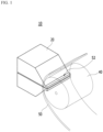
- FIG. 1 a schematic view of the process of manufacturing the electrode sheet is shown in FIG. 1 .
- the electrode sheet is manufactured via a process of allowing a metal sheet 50 moved by a rewinder 40 to contact a slot die coater 20 for discharging electrode slurry and then coating the electrode slurry on the metal sheet 50 to constitute a line 52.
- the electrode line 52 may be formed in one number or may be formed in two or plural number by repeating a plurality of coating processes.
- the metal sheet 50 on which the electrode line 52 is formed may be notched with a desired shape and size to manufacture one unit electrode.
- the rechargeable battery is manufactured with an irregular design of a geometric structure, departing from an already known rectangular or cylindrical structure.
- an 'L' shaped irregular rechargeable battery with lack of a portion in a long direction has attracted attention to be applied to a slim type, curved type, or various designs, and to embody this, an electrode has also been manufactured with the aforementioned irregular structure.
- a portion 54 of the electrode line 52 which is not included in the irregular shape, is discarded, and thus, main components of the electrode line 52, i.e., expensive materials such as an electrode active material of electrode slurry, a binder, and a solvent are wasted.
- the present invention has been made in an effort to overcome the aforementioned problem of the above conventional art and technical objects requested from the past.
- an embodiment of the present invention provides a method of manufacturing an irregular electrode, including forming an electrode line and notching the electrode line in an irregular shape, for manufacturing an electrode in a desired irregular shape and minimizing electrode slurry that is unnecessarily wasted during the manufacturing process.
- a method of manufacturing an irregular electrode includes: forming a first electrode line by continuously coating first electrode slurry on a metal sheet, forming at least one second electrode line formed with a dotted line shape including a plain portion and positioned in parallel to the first electrode line by intermittently coating second electrode slurry on the metal sheet that does not overlap the electrode line, and forming the irregular electrode by notching the metal sheet with an irregular shape including the second electrode line and the first electrode line except for the plain portion.
- the method of manufacturing an irregular electrode according to the present invention has a first feature of performing coating to configure an irregular shape in which an electrode line itself has the plain portion by combining the first electrode line with a straight line shape and a second electrode line with a dotted line shape including the plain portion.
- electrode slurry is saved by as much as the amount of electrode slurry to be coated on the plain portion of the second electrode line, and thus, it may be possible to reduce manufacturing costs of an electrode.
- the method of manufacturing an irregular electrode according to the present invention includes an operation of performing notching on a portion except for the plain portion in which electrode slurry is not present, and thus, has a second feature of minimizing electrode slurry to be discarded during notching, thereby preventing expensive organic and inorganic materials such as an electrode active material, a binder, a solvent, and a conductive material, which are included in the electrode slurry, from being wasted.
- the forming of the first electrode line and the forming of the second electrode line may be simultaneously performed, and the method may further include rolling and drying the first electrode line and the second electrode line prior to the forming of the irregular electrode.
- the electrode lines may be formed using a slot die coater including a plurality of slurry discharge nozzles, and in detail, the forming of the first electrode line and the forming of the second electrode line may be simultaneously performed using a slot die coater including a first slot nozzle for forming the first electrode line, and a second slot nozzle positioned at opposite ends of the first slot nozzle and configured to form the second electrode line.
- a pair of second electrode lines that extends from opposite boundaries of the first electrode line is formed while the second electrode slurry is coated along the opposite boundaries of the first electrode line.
- first electrode line and the second electrode lines may be integrated into each other on a plan to form one irregular line.
- the second electrode lines connected with one side boundary and the other side boundary of the first electrode line may be symmetrical to each other based on an imaginary line for uniformly dividing the first electrode line between the boundaries.
- the second electrode lines connected with one side boundary and the other side boundary of the first electrode line may be asymmetrical based on an imaginary line for uniformly dividing the first electrode line.
- the forming of the irregular electrode may be performed to form an irregular electrode at each of one side and the other side based on an imaginary line for uniformly dividing the first electrode line between boundaries of the first electrode line.
- the irregular shape includes a first electrode portion included in the first electrode line, and a second electrode portion that is included in the second electrode line, extends from the first electrode portion, and has a smaller size than the first electrode portion to form at least one step difference on a plane, and the forming of the irregular electrode includes notching the metal sheet corresponding to the first electrode portion and the second electrode portion.
- the step difference includes a step difference corner formed at a portion at which an external circumference side of the first electrode portion and an external circumference side of the second electrode portion cross each other at an angle equal to or greater than 30 degrees to an angle less than 180 degrees, and the metal sheet is further notched to form an external circumference indented portion formed by indenting a portion of each of the first electrode portion and the second electrode portion inwardly at the step difference corner.
- the step difference may include two or less of the step corner, and in detail, may include only one of the step corner to form the irregular electrode with an 'L' shape on a plane.
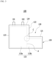
- FIG. 3 is a schematic diagram of a battery cell including an irregular electrode according to the conventional art.
- a battery cell 100 may be configured in such a way that external circumference sides 121, 122, 123, and 124 of a cell case 120 are sealed via thermal bonding in a state in which an electrode assembly 110 is installed in the cell case 120 along with an electrolyte solution.
- the electrode assembly 110 may be configured in such a way that two electrode portions 110a and 110b with different planar shapes and sizes with respect to the ground are separated based on a boundary A, and accordingly, a step difference 130 formed due to the different sizes of the electrode portions 110a and 110b may be formed on the electrode assembly 110.
- the cell case 120 may be configured in a shape corresponding to the electrode assembly 110, and the external circumference sides 121, 122, 123, and 124 may be sealed along end portions of the electrode assembly 110, and thus, the battery cell 100 may be configured with an irregular structure including the step difference 130 to correspond to a shape of the electrode assembly 110, but not a conventional rectangular structure.
- the cell case 120 may be configured in such a way that the different external circumference sides 121 and 122 cross each other to correspond to a shape of an external circumference corner C at the external circumference corner C at a portion at which external circumference sides of the electrode portions 110a and 110b cross each other, and thus, a relatively wide sealing area may be formed at an intersection portion of the external circumference sides 121 and 122.
- a point that shares a sealing portion while the external circumference sides 121 and 122 cross each other has relatively low sealing force compared with other portions, and thus, the external circumference sides 121 and 122 of the cell case 120, adjacent to the external circumference corner C, also requires a relatively wide thermal bonding sealing area compared with the other external circumference sides 123 and 124.
- the structure of the battery cell 100 may be disadvantageous in that spatial utility of a device is degraded by as much as a sealing area which is unnecessarily occupied by the external circumference sides 121 and 122 at the external circumference corner C.
- each of the external circumference sides 121, 122, and 123 that is sealed via thermal bonding in the cell case 120 needs to be bent in a direction of a side surface of the electrode assembly 110 to prevent moisture from penetrating and to reduce an area of a battery cell, but in the structure of FIG. 2 , the external circumference sides 121 and 122 of the cell case 120, adjacent to the external circumference corner C, are connected with each other to correspond to the external circumference corner C, and thus, it may not be easy to bend the external circumference sides 121, 122, and 123 in the direction of the side surface of the electrode assembly 110.
- an irregular electrode may be manufactured to form an external circumference indented portion at an intersection point of the first electrode portion and the second electrode portion cross each other, and thus, a battery cell including the irregular electrode may improve sealing reliability while a cell case is further sealed via thermal bonding at the external circumference indented portion.
- the external circumference indented portion may include, on a plane, a rounded structure including a curved line, a composite structure formed by connecting a curved line and a straight line, or a polygon structure formed by connecting a plurality of straight lines.
- the method of manufacturing the irregular electrode may further include performing notching of forming an electrode tap that protrudes outward from at least one of the first electrode portion and the second electrode portion.
- the method of manufacturing the irregular electrode may further include performing notching of chamfering edges of at least one of the first electrode portion and the second electrode portion.
- the irregular electrode may be a positive electrode or a negative electrode.
- the positive electrode may be manufactured by coating and then drying a mixture of a positive active material, a conductive material, and a binder on, for example, a positive electrode current collector and/or an extension current collector, and as necessary, the mixture may further include a filler.
- the positive electrode current collector and/or the extension current collector may be formed to a thickness of 3 to 500 micrometers.
- the positive electrode current collector and the extension current collector are not particularly limited as long as a corresponding battery has high conductivity while a chemical change is not caused in the battery, and for example, may be formed of stainless steel, aluminum, nickel, titanium, bake carbon, or aluminum, or a material formed by surface-processing a surface of stainless steel with carbon, nickel, titanium, silver, or the like.
- the positive electrode current collector and the extension current collector may have fine protrusions and depressions formed on a surface thereof to enhance adherence of a positive active material, and may be formed in various forms such as a film, a sheet, a foil, a net, a porous body, a foaming body, and a non-woven fabric structure.
- the conductive material may be included with 1 to 30 wt% based on a total weight of a mixture including a positive active material.
- the conductive material is not particularly limited as long as a corresponding battery has high conductivity while a chemical change is not caused in the battery, and for example, may use a conductive material including graphite such as natural graphite or artificial graphite; carbonblack such as carbonblack, acetylene black, ketjen black, channel black, furnace black, lamp black, or thermal black; conductive finer such as carbon fiber or metal fiber; metal powder such as fluoro carbon, aluminum, or nickel powder; conductive whisky such as zinc oxide and potassium titanate; conductive metal oxide such as oxidation titanium; and polyphenylene derivative.
- graphite such as natural graphite or artificial graphite
- carbonblack such as carbonblack, acetylene black, ketjen black, channel black, furnace black, lamp black, or thermal black
- conductive finer such as carbon fiber or metal fiber
- metal powder such as
- the binder may be a component that facilitates coupling of an active material, a conductive material, and so on, and coupling of a current collector, and in general, may be added with 1 to 30 wt% based on a total weight of a mixture including a positive active material.
- binder may include poly vinylidene fluoride, polyvinylalcohol, carboxymethyl cellulose (CMC), starch, hydroxypropyl cellulose, regenerated cellulose, polyvinylpyrrolidone, tetrafluoroethylene, polyethylene, polypropylene, ethylenepropylene-diene terpolymer (EPDM), sulfonate EPDM, styrene butylene rubber, fluorine rubber, and various copolymers.
- CMC carboxymethyl cellulose
- EPDM ethylenepropylene-diene terpolymer
- EPDM ethylenepropylene-diene terpolymer
- EPDM ethylenepropylene-diene terpolymer
- sulfonate EPDM styrene butylene rubber
- fluorine rubber fluorine rubber
- the filler may be selectively used as a component for suppressing expansion of a positive electrode, and is not particularly limited as long as the filler is formed of any material in a fiber phase while a chemical change is not caused in the filler, and may use a material in a fiber phase, for example, an olefin-based polymer such as polyethylene or polypropylene; glass fiber, or carbonfiber.
- a material in a fiber phase for example, an olefin-based polymer such as polyethylene or polypropylene; glass fiber, or carbonfiber.
- the negative electrode may be manufactured by coating and drying a negative active material on a negative electrode current collector and/or an extension current collector, and as necessary, may selectively and further include the aforementioned components.
- the negative electrode current collector and/or the extension current collector may be formed to a thickness of 3 to 500 micrometers.
- the negative electrode current collector and the extension current collector are not particularly limited as long as a corresponding battery has high conductivity while a chemical change is not caused in the battery, and for example, may be formed of copper, stainless steel, aluminum, nickel, titanium, or bake carbon, or a material formed by surface-processing a surface of copper or stainless steel with carbon, nickel, titanium, silver, or the like, or may use an aluminum-cadmium alloy or the like.
- the negative electrode current collector and the extension current collector may have fine protrusions and depressions formed on a surface thereof to enhance adherence of a negative active material, and may be formed in various forms such as a film, a sheet, a foil, a net, a porous body, a foaming body, and a non-woven fabric structure.
- the negative electrode active material may be, for example, carbon such as hard graphitized carbon or graphite-based carbon; Li x Fe 2 O 3 (0 ⁇ x ⁇ 1), Li x WO 2 (0 ⁇ x ⁇ 1), metal composite oxide such as Sn x Me 1-x Me' y O z (Me: Mn, Fe, Pb, Ge; Me': Al, B, P, Si, group 1, 2, or 3 elements in the periodic table, halogen; 0 ⁇ x ⁇ 1; 1 ⁇ y ⁇ 3; 1 ⁇ z ⁇ 8); lithium metal; lithium alloy; silicon-based alloy; tin-based alloy; metal oxide such as SnO, SnO 2 , PbO, PbO 2 , Pb 2 O 3 , Pb 3 O 4 , Sb 2 O 3 , Sb 2 O 4 , Sb 2 O 5 , GeO, GeO 2 , Bi 2 O 3 , Bi 2 O 4 , and Bi 2 O 5 ; and a conductive polymer such as polyacetylene, and a Li-
- the method of manufacturing the irregular electrode according to exemplary embodiments of the present invention may perform coating to configure an irregular shape in which an electrode line itself has the plain portion by combining the first electrode line with a straight line shape and a second electrode line with a dotted line shape including the plain portion, and accordingly, electrode slurry may be advantageously saved by as much as the amount of electrode slurry to be coated on the plain portion of the second electrode line.
- the method may include an operation of performing notching on a portion except for the plain portion in which electrode slurry is not present, and thus, may minimize electrode slurry to be discarded during notching, thereby preventing expensive organic and inorganic materials such as an electrode active material, a binder, a solvent, and a conductive material, which are included in the electrode slurry, from being wasted.
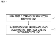
- FIG. 4 is a flowchart of a method of manufacturing an irregular electrode according to an embodiment of the present invention.
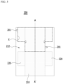
- FIG. 5 is a schematic diagram of a metal sheet.
- first electrode slurry is continuously coated on a metal sheet 200 to form a first electrode line 210
- second electrode slurry is intermittently coated on a portion of the metal sheet 200, which does not overlap the first electrode line 210, to form second electrode lines 220 formed in a dotted line including a plain portion 222 and positioned in parallel to the first electrode line 210.
- the electrode lines 210 and 220 may be formed in operation 1 using a slot die coater including a plurality of slurry discharge nozzles, and in detail, an operation of forming the first electrode line 210 and an operation of forming the second electrode line may be simultaneously performed by a slot die coater including a first slot nozzle for forming the first electrode line 210, and a second slot nozzle positioned at opposite ends of the first slot nozzle and configured to form a second electrode line.
- the second electrode lines 220 connected with one side boundary and the other side boundary of the first electrode line 210 may be symmetrical to each other based on the imaginary line A-A' for uniformly dividing the first electrode line 210 between the boundaries.
- the second electrode lines 220 connected with one side boundary and the other side boundary of the first electrode line 210 may be asymmetrical based on the imaginary line A-A' for uniformly dividing the first electrode line 210.
- Formation of the first electrode line 210 and formation of the second electrode lines 220 may be simultaneously performed, and as necessary, the manufacturing method may include an operation of rolling and drying the first electrode line 210 and the second electrode lines 220 after operation 1.
- the metal sheet 200 may be notched along a perforated line X with an irregular shape including the second electrode line 220 and the first electrode line 210 except for the plain portion 222, to form an irregular electrode.
- operation 2 may be performed to form an irregular electrode at each of one side and the other side based on the imaginary line A-A' for uniformly dividing the first electrode line 210 between the boundaries of the first electrode line 210.
- two irregular electrodes may be manufactured per notching.
- notching for forming the electrode tap 201 that protrudes outward from a second electrode portion 221 may be further performed.
- notching for forming the electrode tap 201 that protrudes outward from a first electrode portion 211 may be performed according to a shape of a desired irregular electrode.
- the aforementioned method of manufacturing an irregular electrode according to the present invention may have a first feature of performing coating to configure an irregular shape in which an electrode line itself has the plain portion 222 by combining the first electrode line 210 with a straight line shape and a second electrode line with a dotted line shape including the plain portion 222.
- the method of manufacturing an irregular electrode according to the present invention may include an operation of performing notching on a portion except for the plain portion 222 in which electrode slurry is not present, and thus, may have a second feature of minimizing electrode slurry to be discarded during notching, thereby preventing expensive organic and inorganic materials such as an electrode active material, a binder, a solvent, and a conductive material, which are included in the electrode slurry, from being wasted.
- FIG. 6 is a schematic diagram of an irregular electrode. With reference to FIG. 6 , the electrode with an irregular shape notched in operation 2 will be described in detail.
- the irregular shape of operation 2 may include the first electrode portion 211 included in the first electrode line 210, and the second electrode portion 221 that is included in the second electrode line 220, extends from the first electrode portion 211, and has a smaller size than the first electrode portion 211 to form a step difference 230 on a plane, and notching may be performed to process the metal sheet 200 corresponding to the first electrode portion 211 and the second electrode portion 221.
- the step difference 230 may include a step difference corner 231 formed at a portion at which an external circumference side 214 of the first electrode portion 211 and an external circumference side 224 of the second electrode portion 221 cross each other at about 90 degrees, and in notching of operation 2, notching for forming an external circumference indented portion 240 formed by indenting a portion of each of the first electrode portion 211 and the second electrode portion 221 inward at the step difference corner 231 may be further performed.
- the electrode manufacturing through this process may be form in an 'L' shape on a plane.
Description
- This application claims priority to and the benefit of
Korean Patent Application No. 10-2017-0154709 filed in the Korean Intellectual Property Office on November 20, 2017 - The present invention relates to a method of manufacturing an irregular electrode.
- Along with the development of technologies of mobile devices and an increase in demands for mobile devices, demands in a rechargeable battery as an energy source are remarkably increased, and such a rechargeable battery necessarily includes an electrode assembly as a power generation component.
- An electrode assembly is configured by assembling a positive electrode, a separator, and a negative electrode in a predetermined form, and the positive electrode and the negative electrode may be a plate type electrode formed by coating and drying a positive electrode slurry and a negative electrode slurry including an active material on a current collector formed of metal foil with electric conductivity.
- Manufacture of a plate type electrode may include a process of manufacturing an electrode mixture including an electrode active material, a process of coating the electrode mixture on metal foil to manufacture an electrode sheet, a process of forming an electrode tap on an electrode, a process of rolling electrodes, a process of notching the electrodes to a small width with a desired shape and size to manufacture a unit electrode, and so on.
- Thereamong, a schematic view of the process of manufacturing the electrode sheet is shown in
FIG. 1 . - Referring to
FIG. 1 , according to aprocess 10 of manufacturing an electrode sheet, the electrode sheet is manufactured via a process of allowing ametal sheet 50 moved by arewinder 40 to contact aslot die coater 20 for discharging electrode slurry and then coating the electrode slurry on themetal sheet 50 to constitute aline 52. Theelectrode line 52 may be formed in one number or may be formed in two or plural number by repeating a plurality of coating processes. - As such, the
metal sheet 50 on which theelectrode line 52 is formed may be notched with a desired shape and size to manufacture one unit electrode. - To diversify products using a rechargeable battery and apply the rechargeable battery to various devices with a curved line or a curved surface, the rechargeable battery is manufactured with an irregular design of a geometric structure, departing from an already known rectangular or cylindrical structure.
- As an example of the irregular design, recently, an 'L' shaped irregular rechargeable battery with lack of a portion in a long direction has attracted attention to be applied to a slim type, curved type, or various designs, and to embody this, an electrode has also been manufactured with the aforementioned irregular structure.
- However, when a metal sheet shown in
FIG. 2 is notched in, for example, an irregular shape corresponding to a perforated line c, aportion 54 of theelectrode line 52, which is not included in the irregular shape, is discarded, and thus, main components of theelectrode line 52, i.e., expensive materials such as an electrode active material of electrode slurry, a binder, and a solvent are wasted. - This is the reason for increasing manufacturing costs of an irregular electrode and a rechargeable battery including the irregular electrode, and thus, there is an urgent need for technologies for overcoming this issue. Methods of manufacturing electrodes and electrodes, respectively, are described in
KR2017-0105752 A US2017/110713 A1 , andWO2017/095002 A1 . - The present invention has been made in an effort to overcome the aforementioned problem of the above conventional art and technical objects requested from the past.
- In detail, an embodiment of the present invention provides a method of manufacturing an irregular electrode, including forming an electrode line and notching the electrode line in an irregular shape, for manufacturing an electrode in a desired irregular shape and minimizing electrode slurry that is unnecessarily wasted during the manufacturing process.
- The invention is set out in the appended claims. According to an embodiment of the present invention, a method of manufacturing an irregular electrode includes: forming a first electrode line by continuously coating first electrode slurry on a metal sheet, forming at least one second electrode line formed with a dotted line shape including a plain portion and positioned in parallel to the first electrode line by intermittently coating second electrode slurry on the metal sheet that does not overlap the electrode line, and forming the irregular electrode by notching the metal sheet with an irregular shape including the second electrode line and the first electrode line except for the plain portion.
- That is, the method of manufacturing an irregular electrode according to the present invention has a first feature of performing coating to configure an irregular shape in which an electrode line itself has the plain portion by combining the first electrode line with a straight line shape and a second electrode line with a dotted line shape including the plain portion.
- This means that electrode slurry is saved by as much as the amount of electrode slurry to be coated on the plain portion of the second electrode line, and thus, it may be possible to reduce manufacturing costs of an electrode.
- The method of manufacturing an irregular electrode according to the present invention includes an operation of performing notching on a portion except for the plain portion in which electrode slurry is not present, and thus, has a second feature of minimizing electrode slurry to be discarded during notching, thereby preventing expensive organic and inorganic materials such as an electrode active material, a binder, a solvent, and a conductive material, which are included in the electrode slurry, from being wasted.
- In the present invention, the forming of the first electrode line and the forming of the second electrode line may be simultaneously performed, and the method may further include rolling and drying the first electrode line and the second electrode line prior to the forming of the irregular electrode.
- The electrode lines may be formed using a slot die coater including a plurality of slurry discharge nozzles, and in detail, the forming of the first electrode line and the forming of the second electrode line may be simultaneously performed using a slot die coater including a first slot nozzle for forming the first electrode line, and a second slot nozzle positioned at opposite ends of the first slot nozzle and configured to form the second electrode line.
- Hereinafter, a detailed process for completing a shape of an irregular electrode using a manufacturing method according to the present invention will be described in detail through unlimited examples.
- In one example, in the forming of the second electrode line, a pair of second electrode lines that extends from opposite boundaries of the first electrode line is formed while the second electrode slurry is coated along the opposite boundaries of the first electrode line.
- That is, the first electrode line and the second electrode lines may be integrated into each other on a plan to form one irregular line.
- In an example of the irregular line, the second electrode lines connected with one side boundary and the other side boundary of the first electrode line may be symmetrical to each other based on an imaginary line for uniformly dividing the first electrode line between the boundaries.
- As another example, the second electrode lines connected with one side boundary and the other side boundary of the first electrode line may be asymmetrical based on an imaginary line for uniformly dividing the first electrode line.
- The forming of the irregular electrode may be performed to form an irregular electrode at each of one side and the other side based on an imaginary line for uniformly dividing the first electrode line between boundaries of the first electrode line.
- Accordingly, while notching may be performed at one side and the other side based on an imaginary line, two irregular electrodes may be manufactured per notching.
- As an example, the irregular shape includes a first electrode portion included in the first electrode line, and a second electrode portion that is included in the second electrode line, extends from the first electrode portion, and has a smaller size than the first electrode portion to form at least one step difference on a plane, and the forming of the irregular electrode includes notching the metal sheet corresponding to the first electrode portion and the second electrode portion.
- The step difference includes a step difference corner formed at a portion at which an external circumference side of the first electrode portion and an external circumference side of the second electrode portion cross each other at an angle equal to or greater than 30 degrees to an angle less than 180 degrees, and the metal sheet is further notched to form an external circumference indented portion formed by indenting a portion of each of the first electrode portion and the second electrode portion inwardly at the step difference corner.
- The step difference may include two or less of the step corner, and in detail, may include only one of the step corner to form the irregular electrode with an 'L' shape on a plane.
-
FIG. 3 is a schematic diagram of a battery cell including an irregular electrode according to the conventional art. - Referring to
FIG. 3 , abattery cell 100 may be configured in such a way thatexternal circumference sides cell case 120 are sealed via thermal bonding in a state in which anelectrode assembly 110 is installed in thecell case 120 along with an electrolyte solution. - In detail, the
electrode assembly 110 may be configured in such a way that twoelectrode portions step difference 130 formed due to the different sizes of theelectrode portions electrode assembly 110. Thecell case 120 may be configured in a shape corresponding to theelectrode assembly 110, and theexternal circumference sides electrode assembly 110, and thus, thebattery cell 100 may be configured with an irregular structure including thestep difference 130 to correspond to a shape of theelectrode assembly 110, but not a conventional rectangular structure. - In the structure of the
battery cell 100 shown inFIG. 3 , thecell case 120 may be configured in such a way that the differentexternal circumference sides electrode portions external circumference sides - In addition, a point that shares a sealing portion while the external circumference sides 121 and 122 cross each other has relatively low sealing force compared with other portions, and thus, the
external circumference sides cell case 120, adjacent to the external circumference corner C, also requires a relatively wide thermal bonding sealing area compared with the otherexternal circumference sides - Accordingly, the structure of the
battery cell 100 may be disadvantageous in that spatial utility of a device is degraded by as much as a sealing area which is unnecessarily occupied by theexternal circumference sides - In general, except for the
external circumference side 124 on which electrode leads 101 and 102 are formed, each of theexternal circumference sides cell case 120 needs to be bent in a direction of a side surface of theelectrode assembly 110 to prevent moisture from penetrating and to reduce an area of a battery cell, but in the structure ofFIG. 2 , theexternal circumference sides cell case 120, adjacent to the external circumference corner C, are connected with each other to correspond to the external circumference corner C, and thus, it may not be easy to bend theexternal circumference sides electrode assembly 110. - If a portion at which the
external circumference sides cell case 120 is not ensured between the external circumference corner C and the cutting portion, and thus, there is a problem in that a sealing state is easily released. - Accordingly, according to the present invention, an irregular electrode may be manufactured to form an external circumference indented portion at an intersection point of the first electrode portion and the second electrode portion cross each other, and thus, a battery cell including the irregular electrode may improve sealing reliability while a cell case is further sealed via thermal bonding at the external circumference indented portion.
- The external circumference indented portion may include, on a plane, a rounded structure including a curved line, a composite structure formed by connecting a curved line and a straight line, or a polygon structure formed by connecting a plurality of straight lines.
- The method of manufacturing the irregular electrode may further include performing notching of forming an electrode tap that protrudes outward from at least one of the first electrode portion and the second electrode portion.
- The method of manufacturing the irregular electrode may further include performing notching of chamfering edges of at least one of the first electrode portion and the second electrode portion.
- The irregular electrode may be a positive electrode or a negative electrode.
- The positive electrode may be manufactured by coating and then drying a mixture of a positive active material, a conductive material, and a binder on, for example, a positive electrode current collector and/or an extension current collector, and as necessary, the mixture may further include a filler.
- In general, the positive electrode current collector and/or the extension current collector may be formed to a thickness of 3 to 500 micrometers. The positive electrode current collector and the extension current collector are not particularly limited as long as a corresponding battery has high conductivity while a chemical change is not caused in the battery, and for example, may be formed of stainless steel, aluminum, nickel, titanium, bake carbon, or aluminum, or a material formed by surface-processing a surface of stainless steel with carbon, nickel, titanium, silver, or the like. The positive electrode current collector and the extension current collector may have fine protrusions and depressions formed on a surface thereof to enhance adherence of a positive active material, and may be formed in various forms such as a film, a sheet, a foil, a net, a porous body, a foaming body, and a non-woven fabric structure.
- The positive active material may be a layered compound such as lithium cobalt oxide (LiCoO2) or lithium nickel oxide (LiNiO2) or a compound substituted with one or more transition elements; lithium manganese oxide represented by chemical formulae Li1+xMn2-xO4 (where x is 0 to 0.33), LiMnOa, LiMn2O3, and LiMnO2; lithium copper oxide (Li2CuO2); vanadium oxide such as LiVsOs, LiFe3O4, V2O5, and Cu2V2O7; Ni site-type lithium nickel oxide represented by chemical formula LiNi1-xMxO2 (where M = Co, Mn, Al, Cu, Fe, Mg, B or Ga, and x = 0.01 to 0.3); lithium manganese composite oxide represented by chemical formula LiMn2-xMxO2 (where M = Co, Ni, Fe, Cr, Zn or Ta and x = 0.01 to 0.1) or Li2Mn3MO8 (where M = Fe, Co, Ni, Cu, or Zn); LiMn2O4 with an Li portion of chemical formula substituted with an alkaline earth metal ion; a disulfide compound; Fe2(MoO4)3, and so on, but is not limited thereto.
- In general, the conductive material may be included with 1 to 30 wt% based on a total weight of a mixture including a positive active material. The conductive material is not particularly limited as long as a corresponding battery has high conductivity while a chemical change is not caused in the battery, and for example, may use a conductive material including graphite such as natural graphite or artificial graphite; carbonblack such as carbonblack, acetylene black, ketjen black, channel black, furnace black, lamp black, or thermal black; conductive finer such as carbon fiber or metal fiber; metal powder such as fluoro carbon, aluminum, or nickel powder; conductive whisky such as zinc oxide and potassium titanate; conductive metal oxide such as oxidation titanium; and polyphenylene derivative.
- The binder may be a component that facilitates coupling of an active material, a conductive material, and so on, and coupling of a current collector, and in general, may be added with 1 to 30 wt% based on a total weight of a mixture including a positive active material. An example of the binder may include poly vinylidene fluoride, polyvinylalcohol, carboxymethyl cellulose (CMC), starch, hydroxypropyl cellulose, regenerated cellulose, polyvinylpyrrolidone, tetrafluoroethylene, polyethylene, polypropylene, ethylenepropylene-diene terpolymer (EPDM), sulfonate EPDM, styrene butylene rubber, fluorine rubber, and various copolymers.
- The filler may be selectively used as a component for suppressing expansion of a positive electrode, and is not particularly limited as long as the filler is formed of any material in a fiber phase while a chemical change is not caused in the filler, and may use a material in a fiber phase, for example, an olefin-based polymer such as polyethylene or polypropylene; glass fiber, or carbonfiber.
- The negative electrode may be manufactured by coating and drying a negative active material on a negative electrode current collector and/or an extension current collector, and as necessary, may selectively and further include the aforementioned components.
- In general, the negative electrode current collector and/or the extension current collector may be formed to a thickness of 3 to 500 micrometers. The negative electrode current collector and the extension current collector are not particularly limited as long as a corresponding battery has high conductivity while a chemical change is not caused in the battery, and for example, may be formed of copper, stainless steel, aluminum, nickel, titanium, or bake carbon, or a material formed by surface-processing a surface of copper or stainless steel with carbon, nickel, titanium, silver, or the like, or may use an aluminum-cadmium alloy or the like. Like the positive electrode current collector, the negative electrode current collector and the extension current collector may have fine protrusions and depressions formed on a surface thereof to enhance adherence of a negative active material, and may be formed in various forms such as a film, a sheet, a foil, a net, a porous body, a foaming body, and a non-woven fabric structure.
- The negative electrode active material may be, for example, carbon such as hard graphitized carbon or graphite-based carbon;
LixFe2O3 (0≤x≤1), LixWO2 (0≤x≤1), metal composite oxide such as SnxMe1-xMe'yOz (Me: Mn, Fe, Pb, Ge; Me': Al, B, P, Si,group - As described above, the method of manufacturing the irregular electrode according to exemplary embodiments of the present invention may perform coating to configure an irregular shape in which an electrode line itself has the plain portion by combining the first electrode line with a straight line shape and a second electrode line with a dotted line shape including the plain portion, and accordingly, electrode slurry may be advantageously saved by as much as the amount of electrode slurry to be coated on the plain portion of the second electrode line.
- In addition, the method may include an operation of performing notching on a portion except for the plain portion in which electrode slurry is not present, and thus, may minimize electrode slurry to be discarded during notching, thereby preventing expensive organic and inorganic materials such as an electrode active material, a binder, a solvent, and a conductive material, which are included in the electrode slurry, from being wasted.
-
-
FIG. 1 is a schematic diagram of a method of manufacturing an electrode according to the conventional art. -
FIG. 2 is a schematic plan view of a metal sheet on which electrode slurry is coated according to the conventional art. -
FIG. 3 is a schematic diagram of an irregular battery cell according to the conventional art. -
FIG. 4 is a flowchart of a manufacturing method (not according to the present invention). -
FIG. 5 is a schematic plan view showing a metal sheet manufactured using a manufacturing method and a notching method (not according to the present invention). -
FIG. 6 is a schematic plan view showing an irregular electrode manufactured using the manufacturing method according to the present invention. - Hereinafter, embodiments of the present invention will be described in detail with reference to the accompanying drawings. However, in the following description of the present invention, a detailed description of known functions or configurations incorporated herein will be omitted for clarifying the subject matter of the present invention.
- To clearly describe the present invention, a part without concerning to the description is omitted in the drawings, and like reference numerals in the specification denote like elements. Sizes and thicknesses of the elements shown in the drawings are for the purpose of descriptive convenience, and thus the present invention is not necessarily limited thereto.
-
FIG. 4 is a flowchart of a method of manufacturing an irregular electrode according to an embodiment of the present invention.FIG. 5 is a schematic diagram of a metal sheet. - Referring to the drawings, in
operation 1 of the manufacturing method according to an exemplary embodiment of the present invention, first electrode slurry is continuously coated on ametal sheet 200 to form afirst electrode line 210, and second electrode slurry is intermittently coated on a portion of themetal sheet 200, which does not overlap thefirst electrode line 210, to formsecond electrode lines 220 formed in a dotted line including aplain portion 222 and positioned in parallel to thefirst electrode line 210. - Although not illustrated in the drawing, the
electrode lines operation 1 using a slot die coater including a plurality of slurry discharge nozzles, and in detail, an operation of forming thefirst electrode line 210 and an operation of forming the second electrode line may be simultaneously performed by a slot die coater including a first slot nozzle for forming thefirst electrode line 210, and a second slot nozzle positioned at opposite ends of the first slot nozzle and configured to form a second electrode line. - In
operation 1, thesecond electrode lines 220 connected with one side boundary and the other side boundary of thefirst electrode line 210 may be symmetrical to each other based on the imaginary line A-A' for uniformly dividing thefirst electrode line 210 between the boundaries. - If necessary, the
second electrode lines 220 connected with one side boundary and the other side boundary of thefirst electrode line 210 may be asymmetrical based on the imaginary line A-A' for uniformly dividing thefirst electrode line 210. - Formation of the
first electrode line 210 and formation of thesecond electrode lines 220 may be simultaneously performed, and as necessary, the manufacturing method may include an operation of rolling and drying thefirst electrode line 210 and thesecond electrode lines 220 afteroperation 1. - Then, in
operation 2, themetal sheet 200 may be notched along a perforated line X with an irregular shape including thesecond electrode line 220 and thefirst electrode line 210 except for theplain portion 222, to form an irregular electrode. - However,
operation 2 may be performed to form an irregular electrode at each of one side and the other side based on the imaginary line A-A' for uniformly dividing thefirst electrode line 210 between the boundaries of thefirst electrode line 210. - Accordingly, while notching is performed at one side and the other side based on an imaginary line, two irregular electrodes may be manufactured per notching.
- In
operation 2, notching for forming theelectrode tap 201 that protrudes outward from a second electrode portion 221 (refer toFIG. 6 ) may be further performed. However, notching for forming theelectrode tap 201 that protrudes outward from a first electrode portion 211 (refer toFIG. 6 ) may be performed according to a shape of a desired irregular electrode. - The aforementioned method of manufacturing an irregular electrode according to the present invention may have a first feature of performing coating to configure an irregular shape in which an electrode line itself has the
plain portion 222 by combining thefirst electrode line 210 with a straight line shape and a second electrode line with a dotted line shape including theplain portion 222. This means that electrode slurry is saved by as much as the amount of electrode slurry to be coated on theplain portion 222 of the second electrode line, and thus, it may be possible to reduce manufacturing costs of an electrode. - The method of manufacturing an irregular electrode according to the present invention may include an operation of performing notching on a portion except for the
plain portion 222 in which electrode slurry is not present, and thus, may have a second feature of minimizing electrode slurry to be discarded during notching, thereby preventing expensive organic and inorganic materials such as an electrode active material, a binder, a solvent, and a conductive material, which are included in the electrode slurry, from being wasted. -
FIG. 6 is a schematic diagram of an irregular electrode. With reference toFIG. 6 , the electrode with an irregular shape notched inoperation 2 will be described in detail. - The irregular shape of
operation 2 may include thefirst electrode portion 211 included in thefirst electrode line 210, and thesecond electrode portion 221 that is included in thesecond electrode line 220, extends from thefirst electrode portion 211, and has a smaller size than thefirst electrode portion 211 to form astep difference 230 on a plane, and notching may be performed to process themetal sheet 200 corresponding to thefirst electrode portion 211 and thesecond electrode portion 221. - Here, the
step difference 230 may include astep difference corner 231 formed at a portion at which anexternal circumference side 214 of thefirst electrode portion 211 and anexternal circumference side 224 of thesecond electrode portion 221 cross each other at about 90 degrees, and in notching ofoperation 2, notching for forming an external circumferenceindented portion 240 formed by indenting a portion of each of thefirst electrode portion 211 and thesecond electrode portion 221 inward at thestep difference corner 231 may be further performed. - The electrode manufacturing through this process may be form in an 'L' shape on a plane.
- While this invention has been described in connection with what is presently considered to be practical exemplary embodiments, one of ordinary skill in the art will understand that the invention is not limited to the disclosed embodiments, and is changed and modified in various ways without departing from the scope of the claims.
Claims (9)
- A method of manufacturing an irregular electrode, the method comprising:forming a first electrode line by continuously coating first electrode slurry on a metal sheet;forming at least one second electrode line formed with a dotted line shape including a plain portion in which electrode slurry is not present and positioned in parallel to the first electrode line by intermittently coating second electrode slurry on the metal sheet that does not overlap with the first electrode line; andforming the irregular electrode by notching the metal sheet with an irregular shape including the second electrode line and the first electrode line except for the plain portion,wherein the irregular electrode is in L-shape on a plane;
wherein the forming of the second electrode line includes forming a pair of second electrode lines that extends from opposite boundaries of the first electrode line while the second electrode slurry is coated along the opposite boundaries of the first electrode line;wherein the irregular shape includes,a first electrode portion included in the first electrode line, anda second electrode portion that is included in the second electrode line, extends from the first electrode portion, and has a smaller size than the first electrode portion to form at least one step difference on a plan; andthe metal sheet corresponding to the first electrode portion and the second electrode portion is notched;wherein the step difference includes a step difference corner formed at a portion at which an external circumference side of the first electrode portion and an external circumference side of the second electrode portion cross each other at an angle equal to or greater than 30 degrees to an angle less than 180 degrees; andthe metal sheet is further notched to form an external circumference indented portion formed by indenting a portion of each of the first electrode portion and the second electrode portion inwardly at the step difference corner. - The method of claim 1, wherein:
the second electrode lines connected with one side boundary and the other side boundary of the first electrode line are symmetrical to each other based on an imaginary line for uniformly dividing the first electrode line between the boundaries. - The method of claim 1, wherein:
the second electrode lines connected with one side boundary and the other side boundary of the first electrode line are asymmetrical based on an imaginary line for uniformly dividing the first electrode line. - The method of claim 1, wherein:the external circumference indented portion includes: on a plane,a rounded structure including a curved line;a composite structure formed by connecting a curved line and a straight line; ora polygon structure formed by connecting a plurality of straight lines.
- The method of claim 1, wherein:
the step difference includes only one of the step corner. - The method of claim 1, further comprising:
performing notching of forming an electrode tab that protrudes outward from at least one of the first electrode portion and the second electrode portion. - The method of claim 1, further comprising:
performing notching of chamfering edges of at least one of the first electrode portion and the second electrode portion. - The method of claim 1, wherein:
the forming of the first electrode line and the forming of the second electrode line are simultaneously performed, and the method further includes rolling and drying the first electrode line and the second electrode line prior to the forming of the irregular electrode. - The method of claim 1, wherein:
the forming of the first electrode line and the forming of the second electrode line are simultaneously performed using a slot die coater including a first slot nozzle for forming the first electrode line, and a second slot nozzle positioned at opposite ends of the first slot nozzle and configured to form the second electrode line.
Applications Claiming Priority (2)
| Application Number | Priority Date | Filing Date | Title |
|---|---|---|---|
| KR1020170154709A KR102261800B1 (en) | 2017-11-20 | 2017-11-20 | Manufacturing method for irregular electrode |
| PCT/KR2018/013645 WO2019098614A1 (en) | 2017-11-20 | 2018-11-09 | Method for manufacturing irregular electrode |
Publications (3)
| Publication Number | Publication Date |
|---|---|
| EP3605663A1 EP3605663A1 (en) | 2020-02-05 |
| EP3605663A4 EP3605663A4 (en) | 2020-07-08 |
| EP3605663B1 true EP3605663B1 (en) | 2023-11-01 |
Family
ID=66538707
Family Applications (1)
| Application Number | Title | Priority Date | Filing Date |
|---|---|---|---|
| EP18879639.5A Active EP3605663B1 (en) | 2017-11-20 | 2018-11-09 | Method of manufacturing irregular electrode |
Country Status (6)
| Country | Link |
|---|---|
| US (1) | US11283057B2 (en) |
| EP (1) | EP3605663B1 (en) |
| KR (1) | KR102261800B1 (en) |
| CN (1) | CN110546785B (en) |
| PL (1) | PL3605663T3 (en) |
| WO (1) | WO2019098614A1 (en) |
Family Cites Families (25)
| Publication number | Priority date | Publication date | Assignee | Title |
|---|---|---|---|---|
| JP2001006664A (en) * | 1999-06-22 | 2001-01-12 | Matsushita Electric Ind Co Ltd | Coating device |
| JP2002028554A (en) * | 2000-07-14 | 2002-01-29 | Konica Corp | Coating method and coating apparatus |
| JP4075034B2 (en) * | 2001-08-06 | 2008-04-16 | ソニー株式会社 | Nonaqueous electrolyte battery and manufacturing method thereof |
| JP4669641B2 (en) * | 2001-08-24 | 2011-04-13 | Necエナジーデバイス株式会社 | Battery electrode cutting device |
| JP4578311B2 (en) * | 2004-07-28 | 2010-11-10 | 三星エスディアイ株式会社 | Manufacturing method of electrode plate for secondary battery and electrode plate for secondary battery manufactured using the same |
| US8142837B2 (en) | 2005-05-09 | 2012-03-27 | Panasonic Corporation | Method and apparatus for applying electrode mixture paste |
| JP4001187B2 (en) * | 2005-07-08 | 2007-10-31 | 株式会社村田製作所 | Method and apparatus for forming external electrode of electronic component |
| WO2010041399A1 (en) | 2008-10-08 | 2010-04-15 | パナソニック株式会社 | Negative electrode and method for production thereof, and non-aqueous electrolyte secondary battery |
| CN101612691A (en) * | 2009-03-31 | 2009-12-30 | 深圳市吉阳自动化科技有限公司 | Pole piece cutting method |
| CN103098256B (en) * | 2010-03-19 | 2016-01-20 | 株式会社Lg化学 | Pocket type housing and the battery pack comprising this pocket type housing |
| JP2015513182A (en) | 2012-04-16 | 2015-04-30 | エルジー・ケム・リミテッド | Method for manufacturing electrode for lithium secondary battery and electrode manufactured using the same |
| JP2014022149A (en) | 2012-07-17 | 2014-02-03 | Dainippon Screen Mfg Co Ltd | Apparatus of manufacturing electrode for battery, nozzle for manufacturing electrode for battery and method of manufacturing electrode for battery |
| CN104755575B (en) | 2012-11-05 | 2018-02-09 | 日东电工株式会社 | Adhesive tape for electrochemical device |
| JP2014179217A (en) * | 2013-03-14 | 2014-09-25 | Mitsubishi Heavy Ind Ltd | Method for manufacturing secondary battery, and secondary battery |
| CN104377345B (en) * | 2013-08-15 | 2017-06-16 | 纳米新能源(唐山)有限责任公司 | Miniature energy storage device electrode, miniature energy storage device and forming method thereof |
| JP6128282B2 (en) * | 2014-07-10 | 2017-05-17 | 株式会社村田製作所 | Storage device manufacturing method and electrode manufacturing method |
| KR20160048527A (en) * | 2014-10-24 | 2016-05-04 | 주식회사 엘지화학 | A Cutting Method of Irregular Cell and the Irregular Cell Manufactured by The Same |
| JP6819941B2 (en) | 2014-12-16 | 2021-01-27 | エルジー・ケム・リミテッド | A method for manufacturing an electrode for a secondary battery containing a PTC substance and an electrode manufactured thereby. |
| KR101579578B1 (en) | 2015-03-24 | 2015-12-22 | 주식회사 엘지화학 | Preparation method of electrode, electrode formed therefrom, and electrochemical device having the same |
| WO2016186209A1 (en) * | 2015-05-20 | 2016-11-24 | Necエナジーデバイス株式会社 | Secondary battery electrode, secondary battery production method and production device |
| KR101950464B1 (en) | 2015-11-30 | 2019-02-20 | 주식회사 엘지화학 | Battery Cell of Irregular Structure with Improved Sealing Reliability of Cell Case |
| KR101641095B1 (en) | 2016-02-22 | 2016-07-20 | 씨아이에스(주) | Coating apparatus for secondary cell |
| KR101875892B1 (en) * | 2016-03-10 | 2018-07-06 | 씨아이에스(주) | Slurry coating methode for secondary cell and secondary cell manufactured using the same |
| CN110462883B (en) * | 2017-03-29 | 2022-10-11 | 株式会社村田制作所 | Method and apparatus for manufacturing secondary battery |
| WO2018221318A1 (en) * | 2017-06-01 | 2018-12-06 | 株式会社村田製作所 | Method for manufacturing secondary battery |
-
2017
- 2017-11-20 KR KR1020170154709A patent/KR102261800B1/en active IP Right Grant
-
2018
- 2018-11-09 PL PL18879639.5T patent/PL3605663T3/en unknown
- 2018-11-09 WO PCT/KR2018/013645 patent/WO2019098614A1/en unknown
- 2018-11-09 CN CN201880023733.3A patent/CN110546785B/en active Active
- 2018-11-09 US US16/604,334 patent/US11283057B2/en active Active
- 2018-11-09 EP EP18879639.5A patent/EP3605663B1/en active Active
Also Published As
| Publication number | Publication date |
|---|---|
| CN110546785A (en) | 2019-12-06 |
| KR102261800B1 (en) | 2021-06-04 |
| KR20190057587A (en) | 2019-05-29 |
| PL3605663T3 (en) | 2024-02-26 |
| EP3605663A1 (en) | 2020-02-05 |
| EP3605663A4 (en) | 2020-07-08 |
| US11283057B2 (en) | 2022-03-22 |
| US20200152958A1 (en) | 2020-05-14 |
| CN110546785B (en) | 2022-07-22 |
| WO2019098614A1 (en) | 2019-05-23 |
Similar Documents
| Publication | Publication Date | Title |
|---|---|---|
| CN110249455B (en) | Method for manufacturing electrode of rechargeable battery | |
| JP6754768B2 (en) | Non-aqueous electrolyte secondary battery | |
| EP3024084B1 (en) | Method for manufacturing rectangular battery cell using metal plates | |
| EP1851814A1 (en) | Secondary battery of improved lithium ion mobility and cell capacity | |
| TWI496334B (en) | Lithium ion secondary battery and preparation process of same | |
| EP3907784A1 (en) | Electrode and method for manufacturing same | |
| JP2017016812A (en) | Nonaqueous electrolyte secondary battery | |
| CN111527627B (en) | Method for manufacturing negative electrode and negative electrode obtained thereby | |
| EP3605663B1 (en) | Method of manufacturing irregular electrode | |
| KR20200088662A (en) | Method of manufacturing electrode and electrode for secondary battery | |
| EP4027425A1 (en) | Electrode assembly and method for manufacturing same | |
| US20230041411A1 (en) | Electrode and Electrode Assembly | |
| WO2013031213A1 (en) | Electrode plate for non-aqueous secondary battery and non-aqueous secondary battery using same | |
| JP2005339926A (en) | Strip electrode and battery using it | |
| KR101819693B1 (en) | Electrode Assembly Comprising a Plurality of Electrode Units and Single Separator Sheet | |
| KR20190110348A (en) | Method for Preparing Anode and Anode Prepared Therefrom | |
| JP7244384B2 (en) | lithium secondary battery | |
| KR102014458B1 (en) | Electrode assembly with directional thickness and Lithium secondary battery comprising the same | |
| CN115084429A (en) | Positive plate and lithium ion battery | |
| KR20190107503A (en) | Lithium ion secondary cell having multiple substrates | |
| KR20190107467A (en) | Secondary cell improved alignment | |
| JP2017073329A (en) | Nonaqueous electrolyte secondary battery | |
| JPWO2004102703A1 (en) | Nonaqueous electrolyte secondary battery | |
| JP2013206653A (en) | Electrode for lithium ion secondary battery, single battery and lithium ion secondary battery using the same |
Legal Events
| Date | Code | Title | Description |
|---|---|---|---|
| STAA | Information on the status of an ep patent application or granted ep patent |
Free format text: STATUS: THE INTERNATIONAL PUBLICATION HAS BEEN MADE |
|
| PUAI | Public reference made under article 153(3) epc to a published international application that has entered the european phase |
Free format text: ORIGINAL CODE: 0009012 |
|
| STAA | Information on the status of an ep patent application or granted ep patent |
Free format text: STATUS: REQUEST FOR EXAMINATION WAS MADE |
|
| 17P | Request for examination filed |
Effective date: 20191029 |
|
| AK | Designated contracting states |
Kind code of ref document: A1 Designated state(s): AL AT BE BG CH CY CZ DE DK EE ES FI FR GB GR HR HU IE IS IT LI LT LU LV MC MK MT NL NO PL PT RO RS SE SI SK SM TR |
|
| AX | Request for extension of the european patent |
Extension state: BA ME |
|
| A4 | Supplementary search report drawn up and despatched |
Effective date: 20200605 |
|
| RIC1 | Information provided on ipc code assigned before grant |
Ipc: B26F 1/12 20060101ALI20200529BHEP Ipc: H01M 4/04 20060101AFI20200529BHEP Ipc: H01M 4/139 20100101ALI20200529BHEP |
|
| DAV | Request for validation of the european patent (deleted) | ||
| DAX | Request for extension of the european patent (deleted) | ||
| STAA | Information on the status of an ep patent application or granted ep patent |
Free format text: STATUS: EXAMINATION IS IN PROGRESS |
|
| 17Q | First examination report despatched |
Effective date: 20220823 |
|
| GRAP | Despatch of communication of intention to grant a patent |
Free format text: ORIGINAL CODE: EPIDOSNIGR1 |
|
| STAA | Information on the status of an ep patent application or granted ep patent |
Free format text: STATUS: GRANT OF PATENT IS INTENDED |
|
| INTG | Intention to grant announced |
Effective date: 20230622 |
|
| GRAS | Grant fee paid |
Free format text: ORIGINAL CODE: EPIDOSNIGR3 |
|
| GRAA | (expected) grant |
Free format text: ORIGINAL CODE: 0009210 |
|
| STAA | Information on the status of an ep patent application or granted ep patent |
Free format text: STATUS: THE PATENT HAS BEEN GRANTED |
|
| P01 | Opt-out of the competence of the unified patent court (upc) registered |
Effective date: 20230901 |
|
| AK | Designated contracting states |
Kind code of ref document: B1 Designated state(s): AL AT BE BG CH CY CZ DE DK EE ES FI FR GB GR HR HU IE IS IT LI LT LU LV MC MK MT NL NO PL PT RO RS SE SI SK SM TR |
|
| REG | Reference to a national code |
Ref country code: GB Ref legal event code: FG4D |
|
| REG | Reference to a national code |
Ref country code: CH Ref legal event code: EP |
|
| REG | Reference to a national code |
Ref country code: DE Ref legal event code: R096 Ref document number: 602018060606 Country of ref document: DE |
|
| REG | Reference to a national code |
Ref country code: IE Ref legal event code: FG4D |
|
| PGFP | Annual fee paid to national office [announced via postgrant information from national office to epo] |
Ref country code: FR Payment date: 20231121 Year of fee payment: 6 Ref country code: DE Payment date: 20231120 Year of fee payment: 6 |
|
| REG | Reference to a national code |
Ref country code: LT Ref legal event code: MG9D |
|
| REG | Reference to a national code |
Ref country code: NL Ref legal event code: MP Effective date: 20231101 |
|
| PG25 | Lapsed in a contracting state [announced via postgrant information from national office to epo] |
Ref country code: GR Free format text: LAPSE BECAUSE OF FAILURE TO SUBMIT A TRANSLATION OF THE DESCRIPTION OR TO PAY THE FEE WITHIN THE PRESCRIBED TIME-LIMIT Effective date: 20240202 |
|
| PG25 | Lapsed in a contracting state [announced via postgrant information from national office to epo] |
Ref country code: IS Free format text: LAPSE BECAUSE OF FAILURE TO SUBMIT A TRANSLATION OF THE DESCRIPTION OR TO PAY THE FEE WITHIN THE PRESCRIBED TIME-LIMIT Effective date: 20240301 |
|
| PG25 | Lapsed in a contracting state [announced via postgrant information from national office to epo] |
Ref country code: LT Free format text: LAPSE BECAUSE OF FAILURE TO SUBMIT A TRANSLATION OF THE DESCRIPTION OR TO PAY THE FEE WITHIN THE PRESCRIBED TIME-LIMIT Effective date: 20231101 |
|
| REG | Reference to a national code |
Ref country code: AT Ref legal event code: MK05 Ref document number: 1628244 Country of ref document: AT Kind code of ref document: T Effective date: 20231101 |
|
| PG25 | Lapsed in a contracting state [announced via postgrant information from national office to epo] |
Ref country code: NL Free format text: LAPSE BECAUSE OF FAILURE TO SUBMIT A TRANSLATION OF THE DESCRIPTION OR TO PAY THE FEE WITHIN THE PRESCRIBED TIME-LIMIT Effective date: 20231101 |
|
| PG25 | Lapsed in a contracting state [announced via postgrant information from national office to epo] |
Ref country code: AT Free format text: LAPSE BECAUSE OF FAILURE TO SUBMIT A TRANSLATION OF THE DESCRIPTION OR TO PAY THE FEE WITHIN THE PRESCRIBED TIME-LIMIT Effective date: 20231101 |
|
| PG25 | Lapsed in a contracting state [announced via postgrant information from national office to epo] |
Ref country code: ES Free format text: LAPSE BECAUSE OF FAILURE TO SUBMIT A TRANSLATION OF THE DESCRIPTION OR TO PAY THE FEE WITHIN THE PRESCRIBED TIME-LIMIT Effective date: 20231101 |
|
| PG25 | Lapsed in a contracting state [announced via postgrant information from national office to epo] |
Ref country code: NL Free format text: LAPSE BECAUSE OF FAILURE TO SUBMIT A TRANSLATION OF THE DESCRIPTION OR TO PAY THE FEE WITHIN THE PRESCRIBED TIME-LIMIT Effective date: 20231101 Ref country code: LT Free format text: LAPSE BECAUSE OF FAILURE TO SUBMIT A TRANSLATION OF THE DESCRIPTION OR TO PAY THE FEE WITHIN THE PRESCRIBED TIME-LIMIT Effective date: 20231101 Ref country code: IS Free format text: LAPSE BECAUSE OF FAILURE TO SUBMIT A TRANSLATION OF THE DESCRIPTION OR TO PAY THE FEE WITHIN THE PRESCRIBED TIME-LIMIT Effective date: 20240301 Ref country code: GR Free format text: LAPSE BECAUSE OF FAILURE TO SUBMIT A TRANSLATION OF THE DESCRIPTION OR TO PAY THE FEE WITHIN THE PRESCRIBED TIME-LIMIT Effective date: 20240202 Ref country code: ES Free format text: LAPSE BECAUSE OF FAILURE TO SUBMIT A TRANSLATION OF THE DESCRIPTION OR TO PAY THE FEE WITHIN THE PRESCRIBED TIME-LIMIT Effective date: 20231101 Ref country code: BG Free format text: LAPSE BECAUSE OF FAILURE TO SUBMIT A TRANSLATION OF THE DESCRIPTION OR TO PAY THE FEE WITHIN THE PRESCRIBED TIME-LIMIT Effective date: 20240201 Ref country code: AT Free format text: LAPSE BECAUSE OF FAILURE TO SUBMIT A TRANSLATION OF THE DESCRIPTION OR TO PAY THE FEE WITHIN THE PRESCRIBED TIME-LIMIT Effective date: 20231101 Ref country code: PT Free format text: LAPSE BECAUSE OF FAILURE TO SUBMIT A TRANSLATION OF THE DESCRIPTION OR TO PAY THE FEE WITHIN THE PRESCRIBED TIME-LIMIT Effective date: 20240301 |