EP3024084B1 - Method for manufacturing rectangular battery cell using metal plates - Google Patents
Method for manufacturing rectangular battery cell using metal plates Download PDFInfo
- Publication number
- EP3024084B1 EP3024084B1 EP14842727.1A EP14842727A EP3024084B1 EP 3024084 B1 EP3024084 B1 EP 3024084B1 EP 14842727 A EP14842727 A EP 14842727A EP 3024084 B1 EP3024084 B1 EP 3024084B1
- Authority
- EP
- European Patent Office
- Prior art keywords
- bottom portion
- welding
- prismatic
- electrode assembly
- upper portion
- Prior art date
- Legal status (The legal status is an assumption and is not a legal conclusion. Google has not performed a legal analysis and makes no representation as to the accuracy of the status listed.)
- Active
Links
- 238000000034 method Methods 0.000 title claims description 47
- 238000004519 manufacturing process Methods 0.000 title claims description 39
- 229910052751 metal Inorganic materials 0.000 title claims description 24
- 239000002184 metal Substances 0.000 title claims description 24
- 238000003466 welding Methods 0.000 claims description 29
- 238000007789 sealing Methods 0.000 claims description 25
- 239000000463 material Substances 0.000 claims description 16
- 230000008569 process Effects 0.000 claims description 12
- 239000003792 electrolyte Substances 0.000 claims description 9
- 238000005452 bending Methods 0.000 claims description 8
- 239000011248 coating agent Substances 0.000 claims description 6
- 238000000576 coating method Methods 0.000 claims description 6
- 229910052782 aluminium Inorganic materials 0.000 claims description 5
- 238000002347 injection Methods 0.000 claims description 5
- 239000007924 injection Substances 0.000 claims description 5
- 229910000838 Al alloy Inorganic materials 0.000 claims description 4
- XAGFODPZIPBFFR-UHFFFAOYSA-N aluminium Chemical compound [Al] XAGFODPZIPBFFR-UHFFFAOYSA-N 0.000 claims description 4
- 238000005520 cutting process Methods 0.000 claims description 2
- 238000005242 forging Methods 0.000 claims description 2
- TWNQGVIAIRXVLR-UHFFFAOYSA-N oxo(oxoalumanyloxy)alumane Chemical compound O=[Al]O[Al]=O TWNQGVIAIRXVLR-UHFFFAOYSA-N 0.000 claims description 2
- 238000005507 spraying Methods 0.000 claims description 2
- 238000003892 spreading Methods 0.000 claims description 2
- 230000007480 spreading Effects 0.000 claims description 2
- 239000010409 thin film Substances 0.000 claims description 2
- 238000002048 anodisation reaction Methods 0.000 claims 1
- -1 LiV3O8 Chemical class 0.000 description 17
- 229910052744 lithium Inorganic materials 0.000 description 16
- WHXSMMKQMYFTQS-UHFFFAOYSA-N Lithium Chemical compound [Li] WHXSMMKQMYFTQS-UHFFFAOYSA-N 0.000 description 15
- OKTJSMMVPCPJKN-UHFFFAOYSA-N Carbon Chemical compound [C] OKTJSMMVPCPJKN-UHFFFAOYSA-N 0.000 description 10
- 239000007784 solid electrolyte Substances 0.000 description 7
- 239000011255 nonaqueous electrolyte Substances 0.000 description 6
- 229920000642 polymer Polymers 0.000 description 5
- 239000004698 Polyethylene Substances 0.000 description 4
- 239000011230 binding agent Substances 0.000 description 4
- 239000006182 cathode active material Substances 0.000 description 4
- 239000004020 conductor Substances 0.000 description 4
- 239000000945 filler Substances 0.000 description 4
- 229910052742 iron Inorganic materials 0.000 description 4
- XEEYBQQBJWHFJM-UHFFFAOYSA-N iron Substances [Fe] XEEYBQQBJWHFJM-UHFFFAOYSA-N 0.000 description 4
- 229910003002 lithium salt Inorganic materials 0.000 description 4
- 159000000002 lithium salts Chemical class 0.000 description 4
- 239000000203 mixture Substances 0.000 description 4
- 229920000573 polyethylene Polymers 0.000 description 4
- 229910052710 silicon Inorganic materials 0.000 description 4
- WEVYAHXRMPXWCK-UHFFFAOYSA-N Acetonitrile Chemical compound CC#N WEVYAHXRMPXWCK-UHFFFAOYSA-N 0.000 description 3
- HBBGRARXTFLTSG-UHFFFAOYSA-N Lithium ion Chemical compound [Li+] HBBGRARXTFLTSG-UHFFFAOYSA-N 0.000 description 3
- ZMXDDKWLCZADIW-UHFFFAOYSA-N N,N-Dimethylformamide Chemical compound CN(C)C=O ZMXDDKWLCZADIW-UHFFFAOYSA-N 0.000 description 3
- 239000004743 Polypropylene Substances 0.000 description 3
- XUIMIQQOPSSXEZ-UHFFFAOYSA-N Silicon Chemical compound [Si] XUIMIQQOPSSXEZ-UHFFFAOYSA-N 0.000 description 3
- WYURNTSHIVDZCO-UHFFFAOYSA-N Tetrahydrofuran Chemical compound C1CCOC1 WYURNTSHIVDZCO-UHFFFAOYSA-N 0.000 description 3
- 230000015572 biosynthetic process Effects 0.000 description 3
- 229910052799 carbon Inorganic materials 0.000 description 3
- 150000001875 compounds Chemical class 0.000 description 3
- 229910001416 lithium ion Inorganic materials 0.000 description 3
- PXHVJJICTQNCMI-UHFFFAOYSA-N nickel Substances [Ni] PXHVJJICTQNCMI-UHFFFAOYSA-N 0.000 description 3
- 229920001155 polypropylene Polymers 0.000 description 3
- 239000010703 silicon Substances 0.000 description 3
- 239000000126 substance Substances 0.000 description 3
- WNXJIVFYUVYPPR-UHFFFAOYSA-N 1,3-dioxolane Chemical compound C1COCO1 WNXJIVFYUVYPPR-UHFFFAOYSA-N 0.000 description 2
- YEJRWHAVMIAJKC-UHFFFAOYSA-N 4-Butyrolactone Chemical compound O=C1CCCO1 YEJRWHAVMIAJKC-UHFFFAOYSA-N 0.000 description 2
- 229920000049 Carbon (fiber) Polymers 0.000 description 2
- CURLTUGMZLYLDI-UHFFFAOYSA-N Carbon dioxide Chemical compound O=C=O CURLTUGMZLYLDI-UHFFFAOYSA-N 0.000 description 2
- XTHFKEDIFFGKHM-UHFFFAOYSA-N Dimethoxyethane Chemical compound COCCOC XTHFKEDIFFGKHM-UHFFFAOYSA-N 0.000 description 2
- IAZDPXIOMUYVGZ-UHFFFAOYSA-N Dimethylsulphoxide Chemical compound CS(C)=O IAZDPXIOMUYVGZ-UHFFFAOYSA-N 0.000 description 2
- 229920002943 EPDM rubber Polymers 0.000 description 2
- ZHNUHDYFZUAESO-UHFFFAOYSA-N Formamide Chemical compound NC=O ZHNUHDYFZUAESO-UHFFFAOYSA-N 0.000 description 2
- 239000002033 PVDF binder Substances 0.000 description 2
- JUJWROOIHBZHMG-UHFFFAOYSA-N Pyridine Chemical compound C1=CC=NC=C1 JUJWROOIHBZHMG-UHFFFAOYSA-N 0.000 description 2
- KAESVJOAVNADME-UHFFFAOYSA-N Pyrrole Chemical class C=1C=CNC=1 KAESVJOAVNADME-UHFFFAOYSA-N 0.000 description 2
- XLOMVQKBTHCTTD-UHFFFAOYSA-N Zinc monoxide Chemical compound [Zn]=O XLOMVQKBTHCTTD-UHFFFAOYSA-N 0.000 description 2
- 239000011149 active material Substances 0.000 description 2
- 229910045601 alloy Inorganic materials 0.000 description 2
- 239000000956 alloy Substances 0.000 description 2
- 239000006183 anode active material Substances 0.000 description 2
- WMWLMWRWZQELOS-UHFFFAOYSA-N bismuth(iii) oxide Chemical compound O=[Bi]O[Bi]=O WMWLMWRWZQELOS-UHFFFAOYSA-N 0.000 description 2
- 229910052796 boron Inorganic materials 0.000 description 2
- 239000004917 carbon fiber Substances 0.000 description 2
- 230000000052 comparative effect Effects 0.000 description 2
- 229910052802 copper Inorganic materials 0.000 description 2
- 239000010949 copper Substances 0.000 description 2
- GNTDGMZSJNCJKK-UHFFFAOYSA-N divanadium pentaoxide Chemical compound O=[V](=O)O[V](=O)=O GNTDGMZSJNCJKK-UHFFFAOYSA-N 0.000 description 2
- 238000001035 drying Methods 0.000 description 2
- FKRCODPIKNYEAC-UHFFFAOYSA-N ethyl propionate Chemical compound CCOC(=O)CC FKRCODPIKNYEAC-UHFFFAOYSA-N 0.000 description 2
- LYCAIKOWRPUZTN-UHFFFAOYSA-N ethylene glycol Natural products OCCO LYCAIKOWRPUZTN-UHFFFAOYSA-N 0.000 description 2
- 239000002657 fibrous material Substances 0.000 description 2
- 239000010408 film Substances 0.000 description 2
- YBMRDBCBODYGJE-UHFFFAOYSA-N germanium dioxide Chemical compound O=[Ge]=O YBMRDBCBODYGJE-UHFFFAOYSA-N 0.000 description 2
- 239000003365 glass fiber Substances 0.000 description 2
- 229910002804 graphite Inorganic materials 0.000 description 2
- 239000010439 graphite Substances 0.000 description 2
- 229910052736 halogen Inorganic materials 0.000 description 2
- 150000002367 halogens Chemical class 0.000 description 2
- 229910003480 inorganic solid Inorganic materials 0.000 description 2
- 239000011244 liquid electrolyte Substances 0.000 description 2
- AMXOYNBUYSYVKV-UHFFFAOYSA-M lithium bromide Chemical compound [Li+].[Br-] AMXOYNBUYSYVKV-UHFFFAOYSA-M 0.000 description 2
- KWGKDLIKAYFUFQ-UHFFFAOYSA-M lithium chloride Chemical compound [Li+].[Cl-] KWGKDLIKAYFUFQ-UHFFFAOYSA-M 0.000 description 2
- 229910000625 lithium cobalt oxide Inorganic materials 0.000 description 2
- HSZCZNFXUDYRKD-UHFFFAOYSA-M lithium iodide Inorganic materials [Li+].[I-] HSZCZNFXUDYRKD-UHFFFAOYSA-M 0.000 description 2
- BFZPBUKRYWOWDV-UHFFFAOYSA-N lithium;oxido(oxo)cobalt Chemical compound [Li+].[O-][Co]=O BFZPBUKRYWOWDV-UHFFFAOYSA-N 0.000 description 2
- 229910052748 manganese Inorganic materials 0.000 description 2
- 239000011572 manganese Substances 0.000 description 2
- 229910044991 metal oxide Inorganic materials 0.000 description 2
- 150000004706 metal oxides Chemical class 0.000 description 2
- TZIHFWKZFHZASV-UHFFFAOYSA-N methyl formate Chemical compound COC=O TZIHFWKZFHZASV-UHFFFAOYSA-N 0.000 description 2
- 229910052759 nickel Inorganic materials 0.000 description 2
- 229920002451 polyvinyl alcohol Polymers 0.000 description 2
- 235000019422 polyvinyl alcohol Nutrition 0.000 description 2
- 229920002981 polyvinylidene fluoride Polymers 0.000 description 2
- 239000000843 powder Substances 0.000 description 2
- RUOJZAUFBMNUDX-UHFFFAOYSA-N propylene carbonate Chemical compound CC1COC(=O)O1 RUOJZAUFBMNUDX-UHFFFAOYSA-N 0.000 description 2
- 238000003860 storage Methods 0.000 description 2
- VZGDMQKNWNREIO-UHFFFAOYSA-N tetrachloromethane Chemical compound ClC(Cl)(Cl)Cl VZGDMQKNWNREIO-UHFFFAOYSA-N 0.000 description 2
- XOLBLPGZBRYERU-UHFFFAOYSA-N tin dioxide Chemical compound O=[Sn]=O XOLBLPGZBRYERU-UHFFFAOYSA-N 0.000 description 2
- PYOKUURKVVELLB-UHFFFAOYSA-N trimethyl orthoformate Chemical compound COC(OC)OC PYOKUURKVVELLB-UHFFFAOYSA-N 0.000 description 2
- 239000011701 zinc Substances 0.000 description 2
- MIZLGWKEZAPEFJ-UHFFFAOYSA-N 1,1,2-trifluoroethene Chemical compound FC=C(F)F MIZLGWKEZAPEFJ-UHFFFAOYSA-N 0.000 description 1
- ZZXUZKXVROWEIF-UHFFFAOYSA-N 1,2-butylene carbonate Chemical compound CCC1COC(=O)O1 ZZXUZKXVROWEIF-UHFFFAOYSA-N 0.000 description 1
- CYSGHNMQYZDMIA-UHFFFAOYSA-N 1,3-Dimethyl-2-imidazolidinon Chemical compound CN1CCN(C)C1=O CYSGHNMQYZDMIA-UHFFFAOYSA-N 0.000 description 1
- XNWFRZJHXBZDAG-UHFFFAOYSA-N 2-METHOXYETHANOL Chemical class COCCO XNWFRZJHXBZDAG-UHFFFAOYSA-N 0.000 description 1
- JWUJQDFVADABEY-UHFFFAOYSA-N 2-methyltetrahydrofuran Chemical compound CC1CCCO1 JWUJQDFVADABEY-UHFFFAOYSA-N 0.000 description 1
- PPDFQRAASCRJAH-UHFFFAOYSA-N 2-methylthiolane 1,1-dioxide Chemical compound CC1CCCS1(=O)=O PPDFQRAASCRJAH-UHFFFAOYSA-N 0.000 description 1
- BTBUEUYNUDRHOZ-UHFFFAOYSA-N Borate Chemical compound [O-]B([O-])[O-] BTBUEUYNUDRHOZ-UHFFFAOYSA-N 0.000 description 1
- 229910001558 CF3SO3Li Inorganic materials 0.000 description 1
- 229920002134 Carboxymethyl cellulose Polymers 0.000 description 1
- 229910018039 Cu2V2O7 Inorganic materials 0.000 description 1
- OIFBSDVPJOWBCH-UHFFFAOYSA-N Diethyl carbonate Chemical compound CCOC(=O)OCC OIFBSDVPJOWBCH-UHFFFAOYSA-N 0.000 description 1
- LCGLNKUTAGEVQW-UHFFFAOYSA-N Dimethyl ether Chemical group COC LCGLNKUTAGEVQW-UHFFFAOYSA-N 0.000 description 1
- KMTRUDSVKNLOMY-UHFFFAOYSA-N Ethylene carbonate Chemical compound O=C1OCCO1 KMTRUDSVKNLOMY-UHFFFAOYSA-N 0.000 description 1
- PIICEJLVQHRZGT-UHFFFAOYSA-N Ethylenediamine Chemical compound NCCN PIICEJLVQHRZGT-UHFFFAOYSA-N 0.000 description 1
- 229910017354 Fe2(MoO4)3 Inorganic materials 0.000 description 1
- YCKRFDGAMUMZLT-UHFFFAOYSA-N Fluorine atom Chemical compound [F] YCKRFDGAMUMZLT-UHFFFAOYSA-N 0.000 description 1
- 229920002153 Hydroxypropyl cellulose Polymers 0.000 description 1
- 229910000733 Li alloy Inorganic materials 0.000 description 1
- 229910007969 Li-Co-Ni Inorganic materials 0.000 description 1
- 229910006570 Li1+xMn2-xO4 Inorganic materials 0.000 description 1
- 229910006628 Li1+xMn2−xO4 Inorganic materials 0.000 description 1
- 229910010228 Li2Mn3MO8 Inorganic materials 0.000 description 1
- 229910007558 Li2SiS3 Inorganic materials 0.000 description 1
- 229910012722 Li3N-LiI-LiOH Inorganic materials 0.000 description 1
- 229910012716 Li3N-LiI—LiOH Inorganic materials 0.000 description 1
- 229910012734 Li3N—LiI—LiOH Inorganic materials 0.000 description 1
- 229910013043 Li3PO4-Li2S-SiS2 Inorganic materials 0.000 description 1
- 229910013035 Li3PO4-Li2S—SiS2 Inorganic materials 0.000 description 1
- 229910012810 Li3PO4—Li2S-SiS2 Inorganic materials 0.000 description 1
- 229910012797 Li3PO4—Li2S—SiS2 Inorganic materials 0.000 description 1
- 229910012047 Li4SiO4-LiI-LiOH Inorganic materials 0.000 description 1
- 229910012075 Li4SiO4-LiI—LiOH Inorganic materials 0.000 description 1
- 229910012057 Li4SiO4—LiI—LiOH Inorganic materials 0.000 description 1
- 229910010739 Li5Ni2 Inorganic materials 0.000 description 1
- 229910003253 LiB10Cl10 Inorganic materials 0.000 description 1
- 229910000552 LiCF3SO3 Inorganic materials 0.000 description 1
- 229910014172 LiMn2-xMxO2 Inorganic materials 0.000 description 1
- 229910014774 LiMn2O3 Inorganic materials 0.000 description 1
- 229910014437 LiMn2−XMXO2 Inorganic materials 0.000 description 1
- 229910002993 LiMnO2 Inorganic materials 0.000 description 1
- 229910014713 LiMnO3 Inorganic materials 0.000 description 1
- 229910014114 LiNi1-xMxO2 Inorganic materials 0.000 description 1
- 229910014907 LiNi1−xMxO2 Inorganic materials 0.000 description 1
- 229910001290 LiPF6 Inorganic materials 0.000 description 1
- 229910012346 LiSiO4-LiI-LiOH Inorganic materials 0.000 description 1
- 229910012345 LiSiO4-LiI—LiOH Inorganic materials 0.000 description 1
- 229910012348 LiSiO4—LiI—LiOH Inorganic materials 0.000 description 1
- 229910012967 LiV3O4 Inorganic materials 0.000 description 1
- 229910012970 LiV3O8 Inorganic materials 0.000 description 1
- 229910002097 Lithium manganese(III,IV) oxide Inorganic materials 0.000 description 1
- 229910016622 LixFe2O3 Inorganic materials 0.000 description 1
- 229910015103 LixWO2 Inorganic materials 0.000 description 1
- 229910006555 Li—Co—Ni Inorganic materials 0.000 description 1
- KDXKERNSBIXSRK-UHFFFAOYSA-N Lysine Natural products NCCCCC(N)C(O)=O KDXKERNSBIXSRK-UHFFFAOYSA-N 0.000 description 1
- 239000004472 Lysine Substances 0.000 description 1
- 229920000914 Metallic fiber Polymers 0.000 description 1
- SECXISVLQFMRJM-UHFFFAOYSA-N N-Methylpyrrolidone Chemical compound CN1CCCC1=O SECXISVLQFMRJM-UHFFFAOYSA-N 0.000 description 1
- ZHGDJTMNXSOQDT-UHFFFAOYSA-N NP(N)(N)=O.NP(N)(N)=O.NP(N)(N)=O.NP(N)(N)=O.NP(N)(N)=O.NP(N)(N)=O Chemical compound NP(N)(N)=O.NP(N)(N)=O.NP(N)(N)=O.NP(N)(N)=O.NP(N)(N)=O.NP(N)(N)=O ZHGDJTMNXSOQDT-UHFFFAOYSA-N 0.000 description 1
- 229920003171 Poly (ethylene oxide) Polymers 0.000 description 1
- 229920000265 Polyparaphenylene Polymers 0.000 description 1
- XBDQKXXYIPTUBI-UHFFFAOYSA-M Propionate Chemical compound CCC([O-])=O XBDQKXXYIPTUBI-UHFFFAOYSA-M 0.000 description 1
- 208000006930 Pseudomyxoma Peritonei Diseases 0.000 description 1
- 229910006145 SO3Li Inorganic materials 0.000 description 1
- 229920002472 Starch Polymers 0.000 description 1
- NINIDFKCEFEMDL-UHFFFAOYSA-N Sulfur Chemical compound [S] NINIDFKCEFEMDL-UHFFFAOYSA-N 0.000 description 1
- UCKMPCXJQFINFW-UHFFFAOYSA-N Sulphide Chemical compound [S-2] UCKMPCXJQFINFW-UHFFFAOYSA-N 0.000 description 1
- ATJFFYVFTNAWJD-UHFFFAOYSA-N Tin Chemical compound [Sn] ATJFFYVFTNAWJD-UHFFFAOYSA-N 0.000 description 1
- GWEVSGVZZGPLCZ-UHFFFAOYSA-N Titan oxide Chemical compound O=[Ti]=O GWEVSGVZZGPLCZ-UHFFFAOYSA-N 0.000 description 1
- GSEJCLTVZPLZKY-UHFFFAOYSA-N Triethanolamine Chemical compound OCCN(CCO)CCO GSEJCLTVZPLZKY-UHFFFAOYSA-N 0.000 description 1
- QDDVNKWVBSLTMB-UHFFFAOYSA-N [Cu]=O.[Li] Chemical compound [Cu]=O.[Li] QDDVNKWVBSLTMB-UHFFFAOYSA-N 0.000 description 1
- BEKPOUATRPPTLV-UHFFFAOYSA-N [Li].BCl Chemical compound [Li].BCl BEKPOUATRPPTLV-UHFFFAOYSA-N 0.000 description 1
- KLARSDUHONHPRF-UHFFFAOYSA-N [Li].[Mn] Chemical compound [Li].[Mn] KLARSDUHONHPRF-UHFFFAOYSA-N 0.000 description 1
- XHCLAFWTIXFWPH-UHFFFAOYSA-N [O-2].[O-2].[O-2].[O-2].[O-2].[V+5].[V+5] Chemical class [O-2].[O-2].[O-2].[O-2].[O-2].[V+5].[V+5] XHCLAFWTIXFWPH-UHFFFAOYSA-N 0.000 description 1
- KXKVLQRXCPHEJC-UHFFFAOYSA-N acetic acid trimethyl ester Natural products COC(C)=O KXKVLQRXCPHEJC-UHFFFAOYSA-N 0.000 description 1
- 239000006230 acetylene black Substances 0.000 description 1
- 238000001994 activation Methods 0.000 description 1
- 238000007792 addition Methods 0.000 description 1
- 238000013019 agitation Methods 0.000 description 1
- 150000007933 aliphatic carboxylic acids Chemical class 0.000 description 1
- 229910001420 alkaline earth metal ion Inorganic materials 0.000 description 1
- 150000001336 alkenes Chemical class 0.000 description 1
- HSFWRNGVRCDJHI-UHFFFAOYSA-N alpha-acetylene Natural products C#C HSFWRNGVRCDJHI-UHFFFAOYSA-N 0.000 description 1
- 229910000147 aluminium phosphate Inorganic materials 0.000 description 1
- VSCWAEJMTAWNJL-UHFFFAOYSA-K aluminium trichloride Chemical class Cl[Al](Cl)Cl VSCWAEJMTAWNJL-UHFFFAOYSA-K 0.000 description 1
- 150000003863 ammonium salts Chemical class 0.000 description 1
- 238000007743 anodising Methods 0.000 description 1
- LJCFOYOSGPHIOO-UHFFFAOYSA-N antimony pentoxide Inorganic materials O=[Sb](=O)O[Sb](=O)=O LJCFOYOSGPHIOO-UHFFFAOYSA-N 0.000 description 1
- 229910000411 antimony tetroxide Inorganic materials 0.000 description 1
- GHPGOEFPKIHBNM-UHFFFAOYSA-N antimony(3+);oxygen(2-) Chemical compound [O-2].[O-2].[O-2].[Sb+3].[Sb+3] GHPGOEFPKIHBNM-UHFFFAOYSA-N 0.000 description 1
- 229910021383 artificial graphite Inorganic materials 0.000 description 1
- 229910000417 bismuth pentoxide Inorganic materials 0.000 description 1
- 239000006229 carbon black Substances 0.000 description 1
- 239000001569 carbon dioxide Substances 0.000 description 1
- 229910002092 carbon dioxide Inorganic materials 0.000 description 1
- 230000001413 cellular effect Effects 0.000 description 1
- 239000006231 channel black Substances 0.000 description 1
- 229910052804 chromium Inorganic materials 0.000 description 1
- 239000011651 chromium Substances 0.000 description 1
- 239000002131 composite material Substances 0.000 description 1
- 239000006258 conductive agent Substances 0.000 description 1
- 229920001940 conductive polymer Polymers 0.000 description 1
- 229920001577 copolymer Polymers 0.000 description 1
- 150000004292 cyclic ethers Chemical class 0.000 description 1
- IEJIGPNLZYLLBP-UHFFFAOYSA-N dimethyl carbonate Chemical compound COC(=O)OC IEJIGPNLZYLLBP-UHFFFAOYSA-N 0.000 description 1
- 150000004862 dioxolanes Chemical class 0.000 description 1
- NJLLQSBAHIKGKF-UHFFFAOYSA-N dipotassium dioxido(oxo)titanium Chemical compound [K+].[K+].[O-][Ti]([O-])=O NJLLQSBAHIKGKF-UHFFFAOYSA-N 0.000 description 1
- 238000007599 discharging Methods 0.000 description 1
- 238000010494 dissociation reaction Methods 0.000 description 1
- 230000005593 dissociations Effects 0.000 description 1
- 150000002019 disulfides Chemical class 0.000 description 1
- 230000000694 effects Effects 0.000 description 1
- 229920001971 elastomer Polymers 0.000 description 1
- 238000005516 engineering process Methods 0.000 description 1
- 230000007613 environmental effect Effects 0.000 description 1
- 238000003912 environmental pollution Methods 0.000 description 1
- 239000000835 fiber Substances 0.000 description 1
- 229910052731 fluorine Inorganic materials 0.000 description 1
- 239000011737 fluorine Substances 0.000 description 1
- 239000006232 furnace black Substances 0.000 description 1
- PVADDRMAFCOOPC-UHFFFAOYSA-N germanium monoxide Inorganic materials [Ge]=O PVADDRMAFCOOPC-UHFFFAOYSA-N 0.000 description 1
- 150000004820 halides Chemical class 0.000 description 1
- 229910021385 hard carbon Inorganic materials 0.000 description 1
- 239000001863 hydroxypropyl cellulose Substances 0.000 description 1
- 235000010977 hydroxypropyl cellulose Nutrition 0.000 description 1
- 150000002461 imidazolidines Chemical class 0.000 description 1
- 150000003949 imides Chemical class 0.000 description 1
- 239000004615 ingredient Substances 0.000 description 1
- 229910052909 inorganic silicate Inorganic materials 0.000 description 1
- 230000010220 ion permeability Effects 0.000 description 1
- 239000003273 ketjen black Substances 0.000 description 1
- 239000006233 lamp black Substances 0.000 description 1
- 229910052745 lead Inorganic materials 0.000 description 1
- YADSGOSSYOOKMP-UHFFFAOYSA-N lead dioxide Inorganic materials O=[Pb]=O YADSGOSSYOOKMP-UHFFFAOYSA-N 0.000 description 1
- YEXPOXQUZXUXJW-UHFFFAOYSA-N lead(II) oxide Inorganic materials [Pb]=O YEXPOXQUZXUXJW-UHFFFAOYSA-N 0.000 description 1
- XMFOQHDPRMAJNU-UHFFFAOYSA-N lead(II,IV) oxide Inorganic materials O1[Pb]O[Pb]11O[Pb]O1 XMFOQHDPRMAJNU-UHFFFAOYSA-N 0.000 description 1
- 239000001989 lithium alloy Substances 0.000 description 1
- 229910001547 lithium hexafluoroantimonate(V) Inorganic materials 0.000 description 1
- 229910001540 lithium hexafluoroarsenate(V) Inorganic materials 0.000 description 1
- 229910002102 lithium manganese oxide Inorganic materials 0.000 description 1
- QEXMICRJPVUPSN-UHFFFAOYSA-N lithium manganese(2+) oxygen(2-) Chemical group [O-2].[Mn+2].[Li+] QEXMICRJPVUPSN-UHFFFAOYSA-N 0.000 description 1
- IDBFBDSKYCUNPW-UHFFFAOYSA-N lithium nitride Chemical compound [Li]N([Li])[Li] IDBFBDSKYCUNPW-UHFFFAOYSA-N 0.000 description 1
- MHCFAGZWMAWTNR-UHFFFAOYSA-M lithium perchlorate Chemical compound [Li+].[O-]Cl(=O)(=O)=O MHCFAGZWMAWTNR-UHFFFAOYSA-M 0.000 description 1
- 229910001486 lithium perchlorate Inorganic materials 0.000 description 1
- 229910001537 lithium tetrachloroaluminate Inorganic materials 0.000 description 1
- 229910001496 lithium tetrafluoroborate Inorganic materials 0.000 description 1
- HSFDLPWPRRSVSM-UHFFFAOYSA-M lithium;2,2,2-trifluoroacetate Chemical compound [Li+].[O-]C(=O)C(F)(F)F HSFDLPWPRRSVSM-UHFFFAOYSA-M 0.000 description 1
- VROAXDSNYPAOBJ-UHFFFAOYSA-N lithium;oxido(oxo)nickel Chemical compound [Li+].[O-][Ni]=O VROAXDSNYPAOBJ-UHFFFAOYSA-N 0.000 description 1
- URIIGZKXFBNRAU-UHFFFAOYSA-N lithium;oxonickel Chemical class [Li].[Ni]=O URIIGZKXFBNRAU-UHFFFAOYSA-N 0.000 description 1
- 229910052749 magnesium Inorganic materials 0.000 description 1
- 239000002905 metal composite material Substances 0.000 description 1
- VNWKTOKETHGBQD-UHFFFAOYSA-N methane Chemical compound C VNWKTOKETHGBQD-UHFFFAOYSA-N 0.000 description 1
- 229940017219 methyl propionate Drugs 0.000 description 1
- 238000012986 modification Methods 0.000 description 1
- 230000004048 modification Effects 0.000 description 1
- 229910021382 natural graphite Inorganic materials 0.000 description 1
- 150000004767 nitrides Chemical class 0.000 description 1
- 150000005181 nitrobenzenes Chemical class 0.000 description 1
- LYGJENNIWJXYER-UHFFFAOYSA-N nitromethane Chemical compound C[N+]([O-])=O LYGJENNIWJXYER-UHFFFAOYSA-N 0.000 description 1
- 239000004745 nonwoven fabric Substances 0.000 description 1
- JRZJOMJEPLMPRA-UHFFFAOYSA-N olefin Natural products CCCCCCCC=C JRZJOMJEPLMPRA-UHFFFAOYSA-N 0.000 description 1
- 239000005486 organic electrolyte Substances 0.000 description 1
- 239000003960 organic solvent Substances 0.000 description 1
- NBIIXXVUZAFLBC-UHFFFAOYSA-N phosphoric acid Substances OP(O)(O)=O NBIIXXVUZAFLBC-UHFFFAOYSA-N 0.000 description 1
- 150000003014 phosphoric acid esters Chemical class 0.000 description 1
- 229910052698 phosphorus Inorganic materials 0.000 description 1
- 229920001197 polyacetylene Polymers 0.000 description 1
- 229920000728 polyester Polymers 0.000 description 1
- 229920000306 polymethylpentene Polymers 0.000 description 1
- 229920000098 polyolefin Polymers 0.000 description 1
- 229920001451 polypropylene glycol Polymers 0.000 description 1
- 229920000036 polyvinylpyrrolidone Polymers 0.000 description 1
- 239000001267 polyvinylpyrrolidone Substances 0.000 description 1
- 235000013855 polyvinylpyrrolidone Nutrition 0.000 description 1
- 239000011148 porous material Substances 0.000 description 1
- UMJSCPRVCHMLSP-UHFFFAOYSA-N pyridine Natural products COC1=CC=CN=C1 UMJSCPRVCHMLSP-UHFFFAOYSA-N 0.000 description 1
- 239000001008 quinone-imine dye Substances 0.000 description 1
- 239000004627 regenerated cellulose Substances 0.000 description 1
- 238000005096 rolling process Methods 0.000 description 1
- 239000005060 rubber Substances 0.000 description 1
- 239000004065 semiconductor Substances 0.000 description 1
- 230000035939 shock Effects 0.000 description 1
- 239000000243 solution Substances 0.000 description 1
- 239000002904 solvent Substances 0.000 description 1
- 239000008107 starch Substances 0.000 description 1
- 235000019698 starch Nutrition 0.000 description 1
- 229920003048 styrene butadiene rubber Polymers 0.000 description 1
- 238000006467 substitution reaction Methods 0.000 description 1
- HXJUTPCZVOIRIF-UHFFFAOYSA-N sulfolane Chemical compound O=S1(=O)CCCC1 HXJUTPCZVOIRIF-UHFFFAOYSA-N 0.000 description 1
- 229920005608 sulfonated EPDM Polymers 0.000 description 1
- 229910052717 sulfur Inorganic materials 0.000 description 1
- 239000011593 sulfur Substances 0.000 description 1
- 150000003467 sulfuric acid derivatives Chemical class 0.000 description 1
- 235000019640 taste Nutrition 0.000 description 1
- BFKJFAAPBSQJPD-UHFFFAOYSA-N tetrafluoroethene Chemical group FC(F)=C(F)F BFKJFAAPBSQJPD-UHFFFAOYSA-N 0.000 description 1
- TXEYQDLBPFQVAA-UHFFFAOYSA-N tetrafluoromethane Chemical compound FC(F)(F)F TXEYQDLBPFQVAA-UHFFFAOYSA-N 0.000 description 1
- YLQBMQCUIZJEEH-UHFFFAOYSA-N tetrahydrofuran Natural products C=1C=COC=1 YLQBMQCUIZJEEH-UHFFFAOYSA-N 0.000 description 1
- 239000006234 thermal black Substances 0.000 description 1
- QHGNHLZPVBIIPX-UHFFFAOYSA-N tin(II) oxide Inorganic materials [Sn]=O QHGNHLZPVBIIPX-UHFFFAOYSA-N 0.000 description 1
- OGIDPMRJRNCKJF-UHFFFAOYSA-N titanium oxide Inorganic materials [Ti]=O OGIDPMRJRNCKJF-UHFFFAOYSA-N 0.000 description 1
- 229910052723 transition metal Inorganic materials 0.000 description 1
- 150000003624 transition metals Chemical group 0.000 description 1
- BDZBKCUKTQZUTL-UHFFFAOYSA-N triethyl phosphite Chemical compound CCOP(OCC)OCC BDZBKCUKTQZUTL-UHFFFAOYSA-N 0.000 description 1
- 229910001935 vanadium oxide Inorganic materials 0.000 description 1
- 239000013585 weight reducing agent Substances 0.000 description 1
- 229910052725 zinc Inorganic materials 0.000 description 1
- 239000011787 zinc oxide Substances 0.000 description 1
Images


Classifications
-
- H—ELECTRICITY
- H01—ELECTRIC ELEMENTS
- H01M—PROCESSES OR MEANS, e.g. BATTERIES, FOR THE DIRECT CONVERSION OF CHEMICAL ENERGY INTO ELECTRICAL ENERGY
- H01M50/00—Constructional details or processes of manufacture of the non-active parts of electrochemical cells other than fuel cells, e.g. hybrid cells
- H01M50/10—Primary casings, jackets or wrappings of a single cell or a single battery
- H01M50/102—Primary casings, jackets or wrappings of a single cell or a single battery characterised by their shape or physical structure
- H01M50/103—Primary casings, jackets or wrappings of a single cell or a single battery characterised by their shape or physical structure prismatic or rectangular
-
- B—PERFORMING OPERATIONS; TRANSPORTING
- B23—MACHINE TOOLS; METAL-WORKING NOT OTHERWISE PROVIDED FOR
- B23K—SOLDERING OR UNSOLDERING; WELDING; CLADDING OR PLATING BY SOLDERING OR WELDING; CUTTING BY APPLYING HEAT LOCALLY, e.g. FLAME CUTTING; WORKING BY LASER BEAM
- B23K26/00—Working by laser beam, e.g. welding, cutting or boring
- B23K26/20—Bonding
- B23K26/21—Bonding by welding
- B23K26/24—Seam welding
- B23K26/26—Seam welding of rectilinear seams
-
- B—PERFORMING OPERATIONS; TRANSPORTING
- B23—MACHINE TOOLS; METAL-WORKING NOT OTHERWISE PROVIDED FOR
- B23K—SOLDERING OR UNSOLDERING; WELDING; CLADDING OR PLATING BY SOLDERING OR WELDING; CUTTING BY APPLYING HEAT LOCALLY, e.g. FLAME CUTTING; WORKING BY LASER BEAM
- B23K26/00—Working by laser beam, e.g. welding, cutting or boring
- B23K26/20—Bonding
- B23K26/32—Bonding taking account of the properties of the material involved
-
- C—CHEMISTRY; METALLURGY
- C25—ELECTROLYTIC OR ELECTROPHORETIC PROCESSES; APPARATUS THEREFOR
- C25D—PROCESSES FOR THE ELECTROLYTIC OR ELECTROPHORETIC PRODUCTION OF COATINGS; ELECTROFORMING; APPARATUS THEREFOR
- C25D11/00—Electrolytic coating by surface reaction, i.e. forming conversion layers
- C25D11/02—Anodisation
- C25D11/04—Anodisation of aluminium or alloys based thereon
-
- H—ELECTRICITY
- H01—ELECTRIC ELEMENTS
- H01M—PROCESSES OR MEANS, e.g. BATTERIES, FOR THE DIRECT CONVERSION OF CHEMICAL ENERGY INTO ELECTRICAL ENERGY
- H01M10/00—Secondary cells; Manufacture thereof
- H01M10/04—Construction or manufacture in general
- H01M10/049—Processes for forming or storing electrodes in the battery container
-
- H—ELECTRICITY
- H01—ELECTRIC ELEMENTS
- H01M—PROCESSES OR MEANS, e.g. BATTERIES, FOR THE DIRECT CONVERSION OF CHEMICAL ENERGY INTO ELECTRICAL ENERGY
- H01M10/00—Secondary cells; Manufacture thereof
- H01M10/05—Accumulators with non-aqueous electrolyte
- H01M10/058—Construction or manufacture
-
- H—ELECTRICITY
- H01—ELECTRIC ELEMENTS
- H01M—PROCESSES OR MEANS, e.g. BATTERIES, FOR THE DIRECT CONVERSION OF CHEMICAL ENERGY INTO ELECTRICAL ENERGY
- H01M50/00—Constructional details or processes of manufacture of the non-active parts of electrochemical cells other than fuel cells, e.g. hybrid cells
- H01M50/10—Primary casings, jackets or wrappings of a single cell or a single battery
-
- B—PERFORMING OPERATIONS; TRANSPORTING
- B23—MACHINE TOOLS; METAL-WORKING NOT OTHERWISE PROVIDED FOR
- B23K—SOLDERING OR UNSOLDERING; WELDING; CLADDING OR PLATING BY SOLDERING OR WELDING; CUTTING BY APPLYING HEAT LOCALLY, e.g. FLAME CUTTING; WORKING BY LASER BEAM
- B23K2103/00—Materials to be soldered, welded or cut
- B23K2103/08—Non-ferrous metals or alloys
- B23K2103/10—Aluminium or alloys thereof
-
- H—ELECTRICITY
- H01—ELECTRIC ELEMENTS
- H01M—PROCESSES OR MEANS, e.g. BATTERIES, FOR THE DIRECT CONVERSION OF CHEMICAL ENERGY INTO ELECTRICAL ENERGY
- H01M10/00—Secondary cells; Manufacture thereof
- H01M10/05—Accumulators with non-aqueous electrolyte
- H01M10/052—Li-accumulators
-
- H—ELECTRICITY
- H01—ELECTRIC ELEMENTS
- H01M—PROCESSES OR MEANS, e.g. BATTERIES, FOR THE DIRECT CONVERSION OF CHEMICAL ENERGY INTO ELECTRICAL ENERGY
- H01M50/00—Constructional details or processes of manufacture of the non-active parts of electrochemical cells other than fuel cells, e.g. hybrid cells
- H01M50/10—Primary casings, jackets or wrappings of a single cell or a single battery
- H01M50/116—Primary casings, jackets or wrappings of a single cell or a single battery characterised by the material
- H01M50/124—Primary casings, jackets or wrappings of a single cell or a single battery characterised by the material having a layered structure
- H01M50/1245—Primary casings, jackets or wrappings of a single cell or a single battery characterised by the material having a layered structure characterised by the external coating on the casing
-
- Y—GENERAL TAGGING OF NEW TECHNOLOGICAL DEVELOPMENTS; GENERAL TAGGING OF CROSS-SECTIONAL TECHNOLOGIES SPANNING OVER SEVERAL SECTIONS OF THE IPC; TECHNICAL SUBJECTS COVERED BY FORMER USPC CROSS-REFERENCE ART COLLECTIONS [XRACs] AND DIGESTS
- Y02—TECHNOLOGIES OR APPLICATIONS FOR MITIGATION OR ADAPTATION AGAINST CLIMATE CHANGE
- Y02E—REDUCTION OF GREENHOUSE GAS [GHG] EMISSIONS, RELATED TO ENERGY GENERATION, TRANSMISSION OR DISTRIBUTION
- Y02E60/00—Enabling technologies; Technologies with a potential or indirect contribution to GHG emissions mitigation
- Y02E60/10—Energy storage using batteries
-
- Y—GENERAL TAGGING OF NEW TECHNOLOGICAL DEVELOPMENTS; GENERAL TAGGING OF CROSS-SECTIONAL TECHNOLOGIES SPANNING OVER SEVERAL SECTIONS OF THE IPC; TECHNICAL SUBJECTS COVERED BY FORMER USPC CROSS-REFERENCE ART COLLECTIONS [XRACs] AND DIGESTS
- Y02—TECHNOLOGIES OR APPLICATIONS FOR MITIGATION OR ADAPTATION AGAINST CLIMATE CHANGE
- Y02P—CLIMATE CHANGE MITIGATION TECHNOLOGIES IN THE PRODUCTION OR PROCESSING OF GOODS
- Y02P70/00—Climate change mitigation technologies in the production process for final industrial or consumer products
- Y02P70/50—Manufacturing or production processes characterised by the final manufactured product
Definitions
- the present invention relates to a method of manufacturing a prismatic battery cell. More particularly, the present invention relates to a method of manufacturing a battery cell including an electrode assembly, which includes a separator interposed between a cathode and an anode and is sealed inside a prismatic battery case, including bending and then welding a metal plate having a predetermined thickness to manufacture a prismatic body in which the upper portion and bottom portion are open, manufacturing upper and bottom portion sealing members corresponding to shape of each of the upper portion and bottom portion of the prismatic body, contacting and then welding the bottom portion of the prismatic body and the bottom portion sealing member, inserting the electrode assembly into the battery case, the bottom portion of which is sealed, and contacting and then welding the upper portion of the battery case and the upper portion sealing member.
- Solar cells are classified into silicon solar cells, thin film-type compound solar cells, layered-type solar cells and the like. Among these solar cells, silicon semiconductor solar cells are the most widely studied.
- An electrode assembly may be configured to have a jelly-roll (wound) type structure in which a long sheet type cathode and a long sheet type anode are wound while a separator is disposed between the cathode and the anode, a stacked type structure in which pluralities of cathodes and anodes having a predetermined size are sequentially stacked while separators are disposed respectively between the cathodes and the anodes, or a stacked/folded type structure in which pluralities of cathodes and anodes having a predetermined size are sequentially stacked while separators are disposed respectively between the cathodes and the anodes to constitute a bi-cell or a full-cell and then a plurality of bi-cells or full-cells is folded, according to the structure of an electrode assembly having a cathode/separator/anode structure.
- secondary batteries are classified into a cylindrical or prismatic battery including an electrode assembly in a cylindrical or rectangular metal can and a pouch type battery including an electrode assembly in a pouch type case made of an aluminum laminate sheet according to shapes of battery cases.
- prismatic batteries having relatively narrow width, according to miniaturization and weight reduction trends of mobile electric devices, have been developed.
- Such prismatic batteries may be applied to different applications than cylindrical type batteries.
- prismatic batteries are manufactured by welding an upper portion cap assembly and injecting an electrolyte thereinto and then sealing an injection port after inserting some battery members into a prismatic hollow case, a bottom portion of which is sealed.
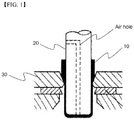
- the prismatic hollow case having the sealed bottom portion is generally manufactured by processing an aluminum alloy plate according to a deep drawing method as exemplified in FIG.1 .
- Deep drawing is a representative forming process of manufacturing a hollow container without a joint using a flat plate in which a plate to be processed 10 disposed on a surface of a die 30 is moved between a punch 20 and die 30 while being compressed in the circumferential direction, resulting in a side wall.
- the deep drawing method Since a plate may be manufactured into a final hollow case through continuous deep drawing processes, the deep drawing method has high efficiency. However, the deep drawing method has some drawbacks as follows.
- materials able to be processed according to the deep drawing method are extremely limited. During the deep drawing process, materials are stretched and, as such, only materials capable of undergoing stretching can be user. However, it is generally difficult to stretch materials having high intensity and, as such, it may be difficult to obtain battery cases having desired characteristics.
- the present invention aims to address the aforementioned problems of the related art and to achieve technical goals that have long been sought.
- the present invention aims to provide a method of manufacturing a prismatic battery cell, production cost of which is reduced due to a simplified manufacturing process and improved production process efficiency, by constituting a battery case such that a prismatic body having an open upper portion and bottom portion by bending and then welding a metal plate having a predetermined thickness, and an upper and bottom portion sealing member corresponding to shape of each of the upper portion and bottom portion of the prismatic body are combined.
- the present invention also aims to provide a method of easily manufacturing a prismatic battery cell while improving a production ratio and obtaining high yield.
- a method of manufacturing a battery cell including an electrode assembly which includes a separator interposed between a cathode and an anode, and is sealed inside a prismatic battery case, the method including:
- a manufacturing cost of the method of manufacturing the battery cell according to the present invention may be reduced by combining together segmented case members, when compared to a deep drawing method.
- the total manufacturing period of the battery cell may be greatly shortened.
- the battery cell may be manufactured in a variety of designs and, at the same time, the error rates of products may be reduced.
- overlapped both end portions of the metal plate bent according to step (a) may be welded in a state that sections of the end portions contact.
- the bent metal plate is welded in a state that the overlapped both end portions are overlapped to a predetermined width.
- a width by which both end portions overlap may be in a range of 0.1 to 10 mm.
- the overlapped portion may be welded after rolling such that the thickness of the overlapped portion is 110% to 150% based on the thickness of the metal plate.
- Such a method of welding a case member is not limited specifically so long as the case member may be combined with high intensity and sealed.
- the welding method may be a laser welding method, arc welding method, electric resistance welding method, gas welding method, ultrasonic welding method, or the like.
- the laser welding method may be more preferable.
- Materials of a metal plate and sealing member constituting the prismatic battery cell according to the present invention are not specifically limited so long as the materials have properties suitable for a battery case, may be manufactured to a plate type and may be used in a manufacturing process of a cell case.
- the materials may be, concretely, aluminum or an aluminum alloy.
- the battery case has a predetermined thickness.
- the battery case may have a thickness of 0.1 to 1 mm.
- the battery case may have a thickness of 0.1 to 1 mm.
- the battery case may not have desired mechanical intensity and the prismatic battery cell may not be protected against external shock. Therefore, the battery case having thickness outside the above range is not preferable.
- the upper portion sealing member and bottom portion sealing member may be manufactured, for example, by a forging, blanking or cutting process.
- the upper portion sealing member may include an electrolyte injection port for electrolyte injection.
- lithium secondary batteries go through a formation process during manufacture of the lithium secondary battery.
- the formation process is a process of charging and discharging the lithium secondary batteries after assembly of the lithium secondary batteries to activate the lithium secondary batteries.
- lithium ions discharged from a cathode of the lithium secondary battery migrate to a carbon electrode, which is used as an anode of the lithium secondary batteries.
- a solid electrolyte interface (SEI) film is formed at the surface of the anode.
- SEI solid electrolyte interface
- the lithium secondary batteries are repeatedly charged and discharged with constant current or constant voltage in a predetermined range.
- at least a portion of outer surfaces of the battery case is coated with an insulative material.
- the insulative material is not specifically restricted so long as the insulative material is coated on the outer surface of the prismatic can to insulate the outer surface of the prismatic can from the outside.
- the coating of the prismatic can with the insulative material may be achieved by anodizing an aluminum oxide on the outer surface of the prismatic can, by spraying the insulative material to the outer surface of the prismatic can, or by spreading an insulative thin film label to the outer surface of the prismatic can.
- the electrode assembly which is not particularly limited, is preferably a folding type electrode assembly, stack type electrode assembly and stack/folding type electrode assembly.
- taps extended from an electrode assembly are combined with one electrode lead. Due to the electrode lead, a planar type electrode terminal is formed.
- Korean Patent Application Pub. Nos. 2001-0082058 , 2001-0082059 and 2001-0082060 particularly disclose with respect to the stack/folding type electrode assembly.
- the applications are combined as references of the present invention.
- the battery pack according to the present invention may be applied to a lithium ion secondary battery in which an electrode assembly is impregnated with a lithium-containing electrolyte, a lithium ion polymer battery in which an electrode assembly is impregnated with a gel-type lithium-containing electrolyte, and the like
- a lithium secondary battery includes a cathode, an anode, a separator, and a lithium salt-containing non-aqueous electrolyte.
- the cathode may be manufactured by, for example, coating a mixture of a cathode active material, a conductive agent, and a binder on a cathode current collector and drying the coated cathode current collector.
- the mixture may further include a filler as desired.
- the conductive material is typically added in an amount of 1 to 30 wt% based on a total weight of a mixture including a cathode active material.
- the conductive material there is no particular limit as to the conductive material, so long as it does not cause chemical changes in the fabricated battery and has conductivity.
- Examples of conductive materials include, but are not limited to, graphite such as natural or artificial graphite; carbon black such as carbon black, acetylene black, Ketjen black, channel black, furnace black, lamp black, and thermal black; conductive fibers such as carbon fibers and metallic fibers; metallic powders such as carbon fluoride powder, aluminum powder, and nickel powder; conductive whiskers such as zinc oxide and potassium titanate; conductive metal oxides such as titanium oxide; and polyphenylene derivatives.
- the binder is a component assisting in binding between an active material and a conductive material and in binding of the active material to a current collector.
- the binder may be typically added in an amount of 1 to 50 wt% based on a total weight of a mixture including a cathode active material.
- binder examples include, but are not limited to, polyvinylidene fluoride, polyvinyl alcohols, carboxymethylcellulose (CMC), starch, hydroxypropylcellulose, regenerated cellulose, polyvinyl pyrrolidone, tetrafluoroethylene, polyethylene, polypropylene, ethylene-propylene-diene terpolymer (EPDM), sulfonated EPDM, styrene-butadiene rubber, fluorine rubber, and various copolymers.
- CMC carboxymethylcellulose
- EPDM ethylene-propylene-diene terpolymer
- EPDM ethylene-propylene-diene terpolymer
- EPDM ethylene-propylene-diene terpolymer
- sulfonated EPDM styrene-butadiene rubber
- fluorine rubber fluorine rubber
- the filler is optionally used as a component to inhibit cathode expansion.
- the filler is not particularly limited so long as it is a fibrous material that does not cause chemical changes in the fabricated secondary battery.
- Examples of the filler include olefin-based polymers such as polyethylene and polypropylene; and fibrous materials such as glass fiber and carbon fiber.
- the anode is manufactured by coating and drying an anode active material on an anode current collector.
- the ingredients described above may be further selectively included.
- anode active material examples include, for example, carbon such as hard carbon and graphite-based carbon; metal composite oxides such as Li x Fe 2 O 3 where 0 ⁇ x ⁇ 1, Li x WO 2 where 0 ⁇ x ⁇ 1, Sn x Me 1-x Me'yO z where Me: Mn, Fe, Pb, or Ge; Me': Al, B, P, Si, Group I, II and III elements, or halogens; 0 ⁇ x ⁇ 1; 1 ⁇ y ⁇ 3; and 1 ⁇ z ⁇ 8; lithium metals; lithium alloys; silicon-based alloys; tin-based alloys; metal oxides such as SnO, SnO 2 , PbO, PbO 2 , Pub 2 O3, Pb 3 O 4 , Sb 2 O 3 , Sb 2 O 4 , Sb 2 O 5 , GeO, GeO 2 , Bi 2 O 3 , Bi 2 O 4 , and Bi 2 O 5 ; conductive polymers such as polyacetylene; and Li-Co-N
- the separator is disposed between the cathode and the anode and, as the separator, a thin insulating film with high ion permeability and high mechanical strength is used.
- the separator generally has a pore diameter of 0.01 to 10 ⁇ m and a thickness of 5 to 300 ⁇ m.
- the separator for example, sheets or non-woven fabrics, made of an olefin polymer such as polypropylene; or glass fibers or polyethylene, which have chemical resistance and hydrophobicity, are used.
- a solid electrolyte such as a polymer or the like is used as an electrolyte
- the solid electrolyte may also serve as a separator.
- the lithium salt-containing non-aqueous electrolyte consists of a polar organic electrolyte and a lithium salt.
- the electrolyte may be a non-aqueous liquid electrolyte, an organic solid electrolyte, an inorganic solid electrolyte, or the like.
- non-aqueous liquid electrolyte examples include non-protic organic solvents such as N-methyl-2-pyrollidinone, propylene carbonate, ethylene carbonate, butylene carbonate, dimethyl carbonate, diethyl carbonate, gamma-butyrolactone, 1,2-dimethoxy ethane, tetrahydrofuran, 2-methyl tetrahydrofuran, dimethylsulfoxide, 1,3-dioxolane, formamide, dimethylformamide, dioxolane, acetonitrile, nitromethane, methyl formate, methyl acetate, phosphoric acid triester, trimethoxy methane, dioxolane derivatives, sulfolane, methyl sulfolane, 1,3-dimethyl-2-imidazolidinone, propylene carbonate derivatives, tetrahydrofuran derivatives, ether, methyl propionate, and ethyl propionate.
- organic solid electrolyte examples include polyethylene derivatives, polyethylene oxide derivatives, polypropylene oxide derivatives, phosphoric acid ester polymers, poly agitation lysine, polyester sulfide, polyvinyl alcohols, polyvinylidene fluoride, and polymers containing ionic dissociation groups.
- Examples of the inorganic solid electrolyte include, without being limited to, nitrides, halides and sulfates of lithium (Li) such as Li 3 N, LiI, Li 5 NI 2 , Li 3 N-LiI-LiOH, LiSiO 4 , LiSiO 4 -LiI-LiOH, Li 2 SiS 3 , Li 4 SiO 4 , Li 4 SiO 4 -LiI-LiOH, and Li 3 PO 4 -Li 2 S-SiS 2 .
- Li lithium
- the lithium salt is a material that is readily soluble in the non-aqueous electrolyte and examples thereof include, without being limited to, LiCl, LiBr, LiI, LiClO 4 , LiBF 4 , LiB 10 Cl 10 , LiPF 6 , LiCF 3 SO 3 , LiCF 3 CO 2 , LiAsF 6 , LiSbF 6 , LiAlCl 4 , CH 3 SO 3 Li, CF 3 SO 3 Li, (CF 3 SO 2 ) 2 NLi, chloroborane lithium, lower aliphatic carboxylic acid lithium, lithium tetraphenyl borate, and imides.
- pyridine triethylphosphite, triethanolamine, cyclic ether, ethylenediamine, n-glyme, hexaphosphoric triamide, nitrobenzene derivatives, sulfur, quinone imine dyes, N-substituted oxazolidinone, N,N-substituted imidazolidine, ethylene glycol dialkyl ether, ammonium salts, pyrrole, 2-methoxy ethanol, aluminum trichloride or the like may be added to the non-aqueous electrolyte.
- the non-aqueous electrolyte may further include halogen-containing solvents such as carbon tetrachloride and ethylene trifluoride. Further, in order to improve high-temperature storage characteristics, the non-aqueous electrolyte may further include carbon dioxide gas.
- the present invention also provides a battery cell manufactured according to the above method.
- the present invention provides a battery pack including at least one prismatic battery cell and a device using the battery pack as a power supply.
- the device may be, concretely, laptop computers, cellular phones, PDPs, PMPs, MP3 players, digital still cameras (DSCs), DVRs, smart phones, GPS systems, camcorders, electric vehicles, hybrid electric vehicles, and plug-in hybrid electric vehicles, power storage devices, and the like.
- a battery case is constituted such that an upper and bottom portion sealing member corresponding to the shape of each of an upper portion and bottom portion of a prismatic body, which has an upper and bottom portion which are open by bending and then welding a metal plate of a predetermined thickness, are combined each other. Consequently, a manufacturing method of the prismatic battery cell is simplified and production process efficiency is improved and, accordingly, manufacturing costs are reduced and a prismatic battery cell which was not manufactured using a deep drawing method may be manufactured.
- FIG. 2 illustrates an exploded perspective view of a prismatic battery cell according to one example of the present invention.
- the prismatic battery cell 100 includes an electrode assembly 110 including a separator interposed between a cathode and an anode embedded in a prismatic battery case.
- a prismatic body 120 having an upper portion and bottom portion which are opened by bending and then welding a metal plate having a predetermined thickness, an upper portion sealing member 130 and bottom portion sealing member 140 corresponding to the shape of each of the upper portion and bottom portion of the prismatic body 120 are respectively manufactured. After inserting the electrode assembly 110 into the battery case, the upper portion sealing member 130 and the bottom portion sealing member 140 contact with the prismatic body 120 and then are welded, resulting in completion of fabrication of a prismatic battery cell 100.
- the prismatic battery cell 100 having such a structure includes a welding side 150 in which end portions of a metal plate at one side of the prismatic battery cell 100 are welded since the prismatic body 120 constituting the prismatic battery cell 100 is manufactured by bending and then welding a metal plate.
- FIG. 3 is a schematic view illustrating a method of manufacturing the prismatic body according to a comparative example.
- FIG. 4 is a schematic view illustrating a method of manufacturing the prismatic body according to the present invention.
- a metal plate 210 which is made of aluminum alloy and has a thickness of, approximately, 0.3 mm, is bent in the shape of the battery case as illustrated in FIG. 3 .
- the bent metal plate 210 contacts with overlapped both end portions 220 and 230 and, at this time, is combined with the both end portions 220 and 230 by laser welding, resulting in a prismatic body 200 having an upper portion and bottom portion which are open.
- both end portions 320 and 330 facing a bent metal plate 310 may be combined by laser welding such that the end portions 320 and 330 are overlapped by, approximately, 0.4 mm, resulting in a prismatic body 300 having an upper portion and bottom portion which are open.
- the end portions 320 and 330 of the metal plate 310 are rolled and welded such that the thickness of the end portions 320 and 330 is 110 to 150% based on the thickness of the metal plate 310.
- the battery cell according to the present invention is manufactured by combining each case member which is segmented and thereby manufacturing costs may be reduced, total manufacturing periods of the battery cell may be greatly shortened, the battery cell may be manufactured in a variety of designs and, at the same time, error rates of products may be reduced.
Description
- The present invention relates to a method of manufacturing a prismatic battery cell. More particularly, the present invention relates to a method of manufacturing a battery cell including an electrode assembly, which includes a separator interposed between a cathode and an anode and is sealed inside a prismatic battery case, including bending and then welding a metal plate having a predetermined thickness to manufacture a prismatic body in which the upper portion and bottom portion are open, manufacturing upper and bottom portion sealing members corresponding to shape of each of the upper portion and bottom portion of the prismatic body, contacting and then welding the bottom portion of the prismatic body and the bottom portion sealing member, inserting the electrode assembly into the battery case, the bottom portion of which is sealed, and contacting and then welding the upper portion of the battery case and the upper portion sealing member.
- Recently, people are more concerned with environmental problems and depletion of natural sources and, as such, interest in solar cells as an alternative energy source which does not cause environmental pollution is growing. Solar cells are classified into silicon solar cells, thin film-type compound solar cells, layered-type solar cells and the like. Among these solar cells, silicon semiconductor solar cells are the most widely studied.
- An electrode assembly may be configured to have a jelly-roll (wound) type structure in which a long sheet type cathode and a long sheet type anode are wound while a separator is disposed between the cathode and the anode, a stacked type structure in which pluralities of cathodes and anodes having a predetermined size are sequentially stacked while separators are disposed respectively between the cathodes and the anodes, or a stacked/folded type structure in which pluralities of cathodes and anodes having a predetermined size are sequentially stacked while separators are disposed respectively between the cathodes and the anodes to constitute a bi-cell or a full-cell and then a plurality of bi-cells or full-cells is folded, according to the structure of an electrode assembly having a cathode/separator/anode structure.
- In addition, secondary batteries are classified into a cylindrical or prismatic battery including an electrode assembly in a cylindrical or rectangular metal can and a pouch type battery including an electrode assembly in a pouch type case made of an aluminum laminate sheet according to shapes of battery cases.
- Especially, prismatic batteries having relatively narrow width, according to miniaturization and weight reduction trends of mobile electric devices, have been developed. Such prismatic batteries may be applied to different applications than cylindrical type batteries.
- Generally, prismatic batteries are manufactured by welding an upper portion cap assembly and injecting an electrolyte thereinto and then sealing an injection port after inserting some battery members into a prismatic hollow case, a bottom portion of which is sealed. Here, the prismatic hollow case having the sealed bottom portion is generally manufactured by processing an aluminum alloy plate according to a deep drawing method as exemplified in
FIG.1 . Deep drawing is a representative forming process of manufacturing a hollow container without a joint using a flat plate in which a plate to be processed 10 disposed on a surface of adie 30 is moved between apunch 20 and die 30 while being compressed in the circumferential direction, resulting in a side wall. - Since a plate may be manufactured into a final hollow case through continuous deep drawing processes, the deep drawing method has high efficiency. However, the deep drawing method has some drawbacks as follows.
- First, since a process of the deep drawing method consists of, approximately, 10 steps or more, and is sophisticated, manufacturing costs related thereto are extremely high. Especially, to manufacture a mold or the like, a long period of 2 to 3 months is generally required and thereby required time to develop batteries in accord with changing tastes of consumers greatly is greatly extended.
- Second, materials able to be processed according to the deep drawing method are extremely limited. During the deep drawing process, materials are stretched and, as such, only materials capable of undergoing stretching can be user. However, it is generally difficult to stretch materials having high intensity and, as such, it may be difficult to obtain battery cases having desired characteristics.
- Finally, when prismatic battery cases are processed according to a deep drawing method and a thickness ratio of a long side and short side of a bottom portion exceeds a predetermined ratio, edge cracks may occur and, as such, an error rate of products is high and case dimensions are limited.
- Therefore, there is an urgent need to develop a technology that can fundamentally address these problems.
- Prismatic battery cases manufactured without the use of deep drawing have been disclosed by
JP2001236929 WO2012073885 . - The present invention aims to address the aforementioned problems of the related art and to achieve technical goals that have long been sought.
- Namely, the present invention aims to provide a method of manufacturing a prismatic battery cell, production cost of which is reduced due to a simplified manufacturing process and improved production process efficiency, by constituting a battery case such that a prismatic body having an open upper portion and bottom portion by bending and then welding a metal plate having a predetermined thickness, and an upper and bottom portion sealing member corresponding to shape of each of the upper portion and bottom portion of the prismatic body are combined.
- The present invention also aims to provide a method of easily manufacturing a prismatic battery cell while improving a production ratio and obtaining high yield.
- In accordance with one aspect of the present invention, provided is a method of manufacturing a battery cell including an electrode assembly which includes a separator interposed between a cathode and an anode, and is sealed inside a prismatic battery case, the method including:
- (a) bending and then welding a metal plate having a predetermined thickness to manufacture a prismatic body in which an upper portion and bottom portion are open;
- (b) manufacturing upper and bottom portion sealing members corresponding to shape of each of an upper portion and a bottom portion of a prismatic body;
- (c) contacting and then welding the bottom portion of the prismatic body and the bottom portion sealing member;
- (d) inserting the electrode assembly into the battery case, the bottom portion of which is sealed, manufactured according to step (c); and
- (e) contacting and then welding the upper portion of the battery case and the upper portion sealing member manufactured according to step (d).
- Therefore, a manufacturing cost of the method of manufacturing the battery cell according to the present invention may be reduced by combining together segmented case members, when compared to a deep drawing method. In addition, the total manufacturing period of the battery cell may be greatly shortened. Further, the battery cell may be manufactured in a variety of designs and, at the same time, the error rates of products may be reduced.
- In one embodiment, overlapped both end portions of the metal plate bent according to step (a) may be welded in a state that sections of the end portions contact. According to the invention, the bent metal plate is welded in a state that the overlapped both end portions are overlapped to a predetermined width..
- In particular, a width by which both end portions overlap may be in a range of 0.1 to 10 mm. The overlapped portion may be welded after rolling such that the thickness of the overlapped portion is 110% to 150% based on the thickness of the metal plate.
- Such a method of welding a case member is not limited specifically so long as the case member may be combined with high intensity and sealed. For example, the welding method may be a laser welding method, arc welding method, electric resistance welding method, gas welding method, ultrasonic welding method, or the like. Among these welding methods, the laser welding method may be more preferable.
- Materials of a metal plate and sealing member constituting the prismatic battery cell according to the present invention are not specifically limited so long as the materials have properties suitable for a battery case, may be manufactured to a plate type and may be used in a manufacturing process of a cell case. The materials may be, concretely, aluminum or an aluminum alloy.
- In addition, the battery case has a predetermined thickness. For example, the battery case may have a thickness of 0.1 to 1 mm. When the battery case is too thick, the total thickness or volume of a final battery cell product may be enlarged. On the contrary, when the battery case is too thin, the battery case may not have desired mechanical intensity and the prismatic battery cell may not be protected against external shock. Therefore, the battery case having thickness outside the above range is not preferable.
- The upper portion sealing member and bottom portion sealing member may be manufactured, for example, by a forging, blanking or cutting process. The upper portion sealing member may include an electrolyte injection port for electrolyte injection.
- Meanwhile, lithium secondary batteries go through a formation process during manufacture of the lithium secondary battery. The formation process is a process of charging and discharging the lithium secondary batteries after assembly of the lithium secondary batteries to activate the lithium secondary batteries. During charging of the lithium secondary batteries, lithium ions discharged from a cathode of the lithium secondary battery migrate to a carbon electrode, which is used as an anode of the lithium secondary batteries. At this time, a solid electrolyte interface (SEI) film is formed at the surface of the anode.
- In the formation process, the lithium secondary batteries are repeatedly charged and discharged with constant current or constant voltage in a predetermined range. To effectively perform the activation process of the battery cell, at least a portion of outer surfaces of the battery case is coated with an insulative material.
- The insulative material is not specifically restricted so long as the insulative material is coated on the outer surface of the prismatic can to insulate the outer surface of the prismatic can from the outside. For example, the coating of the prismatic can with the insulative material may be achieved by anodizing an aluminum oxide on the outer surface of the prismatic can, by spraying the insulative material to the outer surface of the prismatic can, or by spreading an insulative thin film label to the outer surface of the prismatic can.
- The electrode assembly, which is not particularly limited, is preferably a folding type electrode assembly, stack type electrode assembly and stack/folding type electrode assembly. In one embodiment, taps extended from an electrode assembly are combined with one electrode lead. Due to the electrode lead, a planar type electrode terminal is formed.
- Korean Patent Application Pub. Nos.
2001-0082058 2001-0082059 2001-0082060 - The battery pack according to the present invention may be applied to a lithium ion secondary battery in which an electrode assembly is impregnated with a lithium-containing electrolyte, a lithium ion polymer battery in which an electrode assembly is impregnated with a gel-type lithium-containing electrolyte, and the like
- In general, a lithium secondary battery includes a cathode, an anode, a separator, and a lithium salt-containing non-aqueous electrolyte.
- The cathode may be manufactured by, for example, coating a mixture of a cathode active material, a conductive agent, and a binder on a cathode current collector and drying the coated cathode current collector. The mixture may further include a filler as desired.
- Examples of the cathode active material include, without being limited to, layered compounds such as lithium cobalt oxide (LiCoO2) and lithium nickel oxide (LiNiO2) or compounds substituted with one or more transition metals; lithium manganese oxides represented by Li1+xMn2-xO4 where 0≤x≤0.33, such as LiMnO3, LiMn2O3, and LiMnO2; lithium copper oxide (Li2CuO2); vanadium oxides such as LiV3O8, LiV3O4, V2O5, and Cu2V2O7; Ni-site type lithium nickel oxides having the formula LiNi1-xMxO2 where M=Co, Mn, Al, Cu, Fe, Mg, B, or Ga, and 0.01≤x≤0.3; lithium manganese composite oxides having the formula LiMn2-xMxO2 where M=Co, Ni, Fe, Cr, Zn, or Ta, and 0.01≤x≤0.1 or the formula Li2Mn3MO8 where M=Fe, Co, Ni, Cu, or Zn; LiMn2O4 where some of the Li atoms are substituted with alkaline earth metal ions; disulfide compounds; and Fe2(MoO4)3.
- The conductive material is typically added in an amount of 1 to 30 wt% based on a total weight of a mixture including a cathode active material. There is no particular limit as to the conductive material, so long as it does not cause chemical changes in the fabricated battery and has conductivity. Examples of conductive materials include, but are not limited to, graphite such as natural or artificial graphite; carbon black such as carbon black, acetylene black, Ketjen black, channel black, furnace black, lamp black, and thermal black; conductive fibers such as carbon fibers and metallic fibers; metallic powders such as carbon fluoride powder, aluminum powder, and nickel powder; conductive whiskers such as zinc oxide and potassium titanate; conductive metal oxides such as titanium oxide; and polyphenylene derivatives.
- The binder is a component assisting in binding between an active material and a conductive material and in binding of the active material to a current collector. The binder may be typically added in an amount of 1 to 50 wt% based on a total weight of a mixture including a cathode active material. Examples of the binder include, but are not limited to, polyvinylidene fluoride, polyvinyl alcohols, carboxymethylcellulose (CMC), starch, hydroxypropylcellulose, regenerated cellulose, polyvinyl pyrrolidone, tetrafluoroethylene, polyethylene, polypropylene, ethylene-propylene-diene terpolymer (EPDM), sulfonated EPDM, styrene-butadiene rubber, fluorine rubber, and various copolymers.
- The filler is optionally used as a component to inhibit cathode expansion. The filler is not particularly limited so long as it is a fibrous material that does not cause chemical changes in the fabricated secondary battery. Examples of the filler include olefin-based polymers such as polyethylene and polypropylene; and fibrous materials such as glass fiber and carbon fiber.
- The anode is manufactured by coating and drying an anode active material on an anode current collector. In this case, as desired, the ingredients described above may be further selectively included.
- Examples of the anode active material include, for example, carbon such as hard carbon and graphite-based carbon; metal composite oxides such as LixFe2O3 where 0≤x≤1, LixWO2 where 0≤x≤1, SnxMe1-xMe'yOz where Me: Mn, Fe, Pb, or Ge; Me': Al, B, P, Si, Group I, II and III elements, or halogens; 0<x≤1; 1≤y≤3; and 1≤z≤8; lithium metals; lithium alloys; silicon-based alloys; tin-based alloys; metal oxides such as SnO, SnO2, PbO, PbO2, Pub2O3, Pb3O4, Sb2O3, Sb2O4, Sb2O5, GeO, GeO2, Bi2O3, Bi2O4, and Bi2O5; conductive polymers such as polyacetylene; and Li-Co-Ni-based materials.
- The separator is disposed between the cathode and the anode and, as the separator, a thin insulating film with high ion permeability and high mechanical strength is used. The separator generally has a pore diameter of 0.01 to 10 µm and a thickness of 5 to 300 µm. As the separator, for example, sheets or non-woven fabrics, made of an olefin polymer such as polypropylene; or glass fibers or polyethylene, which have chemical resistance and hydrophobicity, are used. When a solid electrolyte such as a polymer or the like is used as an electrolyte, the solid electrolyte may also serve as a separator.
- The lithium salt-containing non-aqueous electrolyte consists of a polar organic electrolyte and a lithium salt. The electrolyte may be a non-aqueous liquid electrolyte, an organic solid electrolyte, an inorganic solid electrolyte, or the like.
- Examples of the non-aqueous liquid electrolyte include non-protic organic solvents such as N-methyl-2-pyrollidinone, propylene carbonate, ethylene carbonate, butylene carbonate, dimethyl carbonate, diethyl carbonate, gamma-butyrolactone, 1,2-dimethoxy ethane, tetrahydrofuran, 2-methyl tetrahydrofuran, dimethylsulfoxide, 1,3-dioxolane, formamide, dimethylformamide, dioxolane, acetonitrile, nitromethane, methyl formate, methyl acetate, phosphoric acid triester, trimethoxy methane, dioxolane derivatives, sulfolane, methyl sulfolane, 1,3-dimethyl-2-imidazolidinone, propylene carbonate derivatives, tetrahydrofuran derivatives, ether, methyl propionate, and ethyl propionate.
- Examples of the organic solid electrolyte include polyethylene derivatives, polyethylene oxide derivatives, polypropylene oxide derivatives, phosphoric acid ester polymers, poly agitation lysine, polyester sulfide, polyvinyl alcohols, polyvinylidene fluoride, and polymers containing ionic dissociation groups.
- Examples of the inorganic solid electrolyte include, without being limited to, nitrides, halides and sulfates of lithium (Li) such as Li3N, LiI, Li5NI2, Li3N-LiI-LiOH, LiSiO4, LiSiO4-LiI-LiOH, Li2SiS3, Li4SiO4, Li4SiO4-LiI-LiOH, and Li3PO4-Li2S-SiS2.
- The lithium salt is a material that is readily soluble in the non-aqueous electrolyte and examples thereof include, without being limited to, LiCl, LiBr, LiI, LiClO4, LiBF4, LiB10Cl10, LiPF6, LiCF3SO3, LiCF3CO2, LiAsF6, LiSbF6, LiAlCl4, CH3SO3Li, CF3SO3Li, (CF3SO2)2NLi, chloroborane lithium, lower aliphatic carboxylic acid lithium, lithium tetraphenyl borate, and imides.
- In addition, in order to improve charge/discharge characteristics and flame retardancy, for example, pyridine, triethylphosphite, triethanolamine, cyclic ether, ethylenediamine, n-glyme, hexaphosphoric triamide, nitrobenzene derivatives, sulfur, quinone imine dyes, N-substituted oxazolidinone, N,N-substituted imidazolidine, ethylene glycol dialkyl ether, ammonium salts, pyrrole, 2-methoxy ethanol, aluminum trichloride or the like may be added to the non-aqueous electrolyte. If necessary, in order to impart incombustibility, the non-aqueous electrolyte may further include halogen-containing solvents such as carbon tetrachloride and ethylene trifluoride. Further, in order to improve high-temperature storage characteristics, the non-aqueous electrolyte may further include carbon dioxide gas.
- The present invention also provides a battery cell manufactured according to the above method.
- In addition, the present invention provides a battery pack including at least one prismatic battery cell and a device using the battery pack as a power supply. The device may be, concretely, laptop computers, cellular phones, PDPs, PMPs, MP3 players, digital still cameras (DSCs), DVRs, smart phones, GPS systems, camcorders, electric vehicles, hybrid electric vehicles, and plug-in hybrid electric vehicles, power storage devices, and the like.
- The structures and manufacturing methods of battery packs and devices are known publicly in the art. Therefore, detailed descriptions of the structures and manufacturing methods are omitted.
- As is apparent from the above description, by using a method of manufacturing the prismatic battery cell according to the present invention, a battery case is constituted such that an upper and bottom portion sealing member corresponding to the shape of each of an upper portion and bottom portion of a prismatic body, which has an upper and bottom portion which are open by bending and then welding a metal plate of a predetermined thickness, are combined each other. Consequently, a manufacturing method of the prismatic battery cell is simplified and production process efficiency is improved and, accordingly, manufacturing costs are reduced and a prismatic battery cell which was not manufactured using a deep drawing method may be manufactured.
- The above and other objects, features and other advantages of the present invention will be more clearly understood from the following detailed description taken in conjunction with the accompanying drawing, in which:
-
FIG. 1 is a schematic view illustrating a portion of a process of manufacturing a prismatic battery case using a deep drawing process; -
FIG. 2 is an exploded perspective view of a prismatic battery cell according to one example of the present invention; -
FIG. 3 is a schematic view illustrating a method of manufacturing a prismatic body according to a comparative example; and -
FIG. 4 is a schematic view illustrating a method of manufacturing a prismatic body according to another example of the present invention. - Now, the present invention will be described in more detail with reference to the following examples. These examples are provided only for illustration of the present invention and should not be construed as limiting the scope and spirit of the present invention.
-
FIG. 2 illustrates an exploded perspective view of a prismatic battery cell according to one example of the present invention. - Referring to
FIG. 2 , theprismatic battery cell 100 according to the present invention includes anelectrode assembly 110 including a separator interposed between a cathode and an anode embedded in a prismatic battery case. - A prismatic body 120 having an upper portion and bottom portion which are opened by bending and then welding a metal plate having a predetermined thickness, an upper
portion sealing member 130 and bottomportion sealing member 140 corresponding to the shape of each of the upper portion and bottom portion of the prismatic body 120 are respectively manufactured. After inserting theelectrode assembly 110 into the battery case, the upperportion sealing member 130 and the bottomportion sealing member 140 contact with the prismatic body 120 and then are welded, resulting in completion of fabrication of aprismatic battery cell 100. - The
prismatic battery cell 100 having such a structure includes awelding side 150 in which end portions of a metal plate at one side of theprismatic battery cell 100 are welded since the prismatic body 120 constituting theprismatic battery cell 100 is manufactured by bending and then welding a metal plate. -
FIG. 3 is a schematic view illustrating a method of manufacturing the prismatic body according to a comparative example. -
FIG. 4 is a schematic view illustrating a method of manufacturing the prismatic body according to the present invention. - First, a
metal plate 210 which is made of aluminum alloy and has a thickness of, approximately, 0.3 mm, is bent in the shape of the battery case as illustrated inFIG. 3 . Thebent metal plate 210 contacts with overlapped bothend portions end portions prismatic body 200 having an upper portion and bottom portion which are open. - Alternatively, as illustrated in
FIG. 4 , both endportions bent metal plate 310 may be combined by laser welding such that theend portions prismatic body 300 having an upper portion and bottom portion which are open. Concretely, theend portions metal plate 310 are rolled and welded such that the thickness of theend portions metal plate 310. - As illustrated in
FIGS. 2 and4 , the battery cell according to the present invention is manufactured by combining each case member which is segmented and thereby manufacturing costs may be reduced, total manufacturing periods of the battery cell may be greatly shortened, the battery cell may be manufactured in a variety of designs and, at the same time, error rates of products may be reduced. - Those skilled in the art will appreciate that various modifications, additions and substitutions are possible, without departing from the scope and spirit of the invention as disclosed in the accompanying claims.
Claims (13)
- A method of manufacturing a battery cell (100), which is sealed inside a prismatic battery case, comprising an electrode assembly (110) comprising a cathode, an anode and a separator interposed between the cathode and the anode, the method comprising:bending and then welding a metal plate (310) having a predetermined thickness to manufacture a prismatic body (300) having an open upper portion and bottom portion;manufacturing upper and bottom portion sealing members (130, 140) corresponding to shape of each of an upper portion and bottom portion of a prismatic body (300);contacting and then welding the bottom portion sealing member (140) with the bottom portion of the prismatic body (300);inserting the electrode assembly (110) into the battery case having a sealed bottom portion manufactured according to the contacting and then welding; andcontacting and then welding the upper portion sealing member (130) with the upper portion of the battery case manufactured according to the inserting,characterized in that
overlapped both end portions (320, 330) of the metal plate (310) bent according to the bending are welded in a state that the overlapped both end portions (320, 330) are overlapped to a predetermined width. - The method according to claim 1, wherein the electrode assembly (110) is a folding type electrode assembly (110), a stack type electrode assembly (110), or a stack/folding type electrode assembly (110).
- The method according to claim 1, wherein the both end portions (320, 330) are overlapped in a range of a width of 0.1 to 10 mm.
- The method according to claim 1, wherein a thickness of an overlapped area of the both end portions (320, 330) is 110% to 150% based on a thickness of a metal plate (310).
- The method according to claim 1, wherein the welding is performed by a laser welding method.
- The method according to claim 1, wherein the upper portion sealing member (130) comprises an electrolyte injection port for electrolyte injection.
- The method according to claim 1, wherein each of the metal plate (310) and the sealing members is made of aluminum or aluminum alloy.
- The method according to claim 1, wherein the metal plate (310) and sealing members have a thickness of 0.1 to 1 mm.
- The method according to claim 1, wherein the upper portion sealing member (130) and bottom portion sealing member (140) are manufactured by a forging process, blanking process or cutting process.
- The method according to claim 1, wherein at least a portion of outer sides of the prismatic battery case is coated with an insulative material.
- The method according to claim 10, wherein the coating is performed by anodization of aluminum oxide.
- The method according to claim 10, wherein the coating is performed by spraying an insulative material.
- The method according to claim 10, wherein the coating is performed by spreading an insulative thin film label.
Applications Claiming Priority (2)
| Application Number | Priority Date | Filing Date | Title |
|---|---|---|---|
| KR1020130106641A KR101563578B1 (en) | 2013-09-05 | 2013-09-05 | Method for Preparation of Prismatic Battery Cell Using Metal Plate |
| PCT/KR2014/006379 WO2015034173A1 (en) | 2013-09-05 | 2014-07-15 | Method for manufacturing rectangular battery cell using metal plates |
Publications (3)
| Publication Number | Publication Date |
|---|---|
| EP3024084A1 EP3024084A1 (en) | 2016-05-25 |
| EP3024084A4 EP3024084A4 (en) | 2016-09-14 |
| EP3024084B1 true EP3024084B1 (en) | 2018-01-03 |
Family
ID=52628598
Family Applications (1)
| Application Number | Title | Priority Date | Filing Date |
|---|---|---|---|
| EP14842727.1A Active EP3024084B1 (en) | 2013-09-05 | 2014-07-15 | Method for manufacturing rectangular battery cell using metal plates |
Country Status (7)
| Country | Link |
|---|---|
| US (1) | US20160204392A1 (en) |
| EP (1) | EP3024084B1 (en) |
| JP (1) | JP6220071B2 (en) |
| KR (1) | KR101563578B1 (en) |
| CN (1) | CN105474453A (en) |
| TW (1) | TWI525877B (en) |
| WO (1) | WO2015034173A1 (en) |
Families Citing this family (11)
| Publication number | Priority date | Publication date | Assignee | Title |
|---|---|---|---|---|
| US10340483B2 (en) | 2014-08-26 | 2019-07-02 | Cps Technology Holdings Llc | Welding process for sealing a battery module |
| JP6536885B2 (en) * | 2015-06-15 | 2019-07-03 | トヨタ自動車株式会社 | Method of manufacturing battery container and battery container |
| KR102139065B1 (en) * | 2017-02-13 | 2020-07-29 | 주식회사 엘지화학 | Cylindrical Battery Cell Comprising Inorganic Material Coating Portion |
| CN110983412B (en) * | 2019-03-26 | 2022-03-29 | 国研新能(深圳)技术有限公司 | Application of hard aluminum oxide film prepared based on in-situ generation method in aluminum-shell lithium battery insulation sealing |
| WO2020204901A1 (en) * | 2019-04-01 | 2020-10-08 | Spear Power Systems, LLC | Apparatus for mitigation of thermal event propagation for battery systems |
| KR20200141201A (en) * | 2019-06-10 | 2020-12-18 | 삼성에스디아이 주식회사 | Secondary battery |
| CN111129574A (en) * | 2019-12-12 | 2020-05-08 | 深圳市东方芯愿新能源有限公司 | Integrally formed rechargeable battery and production method thereof |
| KR20210145489A (en) * | 2020-05-25 | 2021-12-02 | 삼성에스디아이 주식회사 | Secondary battery |
| KR102472909B1 (en) * | 2020-10-12 | 2022-12-01 | 삼성에스디아이 주식회사 | Battery pack |
| DE102021111440A1 (en) | 2021-05-04 | 2022-11-10 | Audi Aktiengesellschaft | Method for providing a cell housing part, cell housing part and battery cell for a high-voltage battery of a motor vehicle |
| CN117691264B (en) * | 2024-02-04 | 2024-04-19 | 蜂巢能源科技股份有限公司 | Battery shell, battery shell and battery |
Family Cites Families (29)
| Publication number | Priority date | Publication date | Assignee | Title |
|---|---|---|---|---|
| KR100515572B1 (en) | 2000-02-08 | 2005-09-20 | 주식회사 엘지화학 | Stacked electrochemical cell and method for preparing the same |
| KR100515571B1 (en) | 2000-02-08 | 2005-09-20 | 주식회사 엘지화학 | Stacked electrochemical cell |
| KR100497147B1 (en) | 2000-02-08 | 2005-06-29 | 주식회사 엘지화학 | Multiply stacked electrochemical cell and method for preparing the same |
| JP2001236929A (en) * | 2000-02-22 | 2001-08-31 | Sumitomo Metal Ind Ltd | Battery case made of titanium |
| JP4316470B2 (en) * | 2003-10-31 | 2009-08-19 | 株式会社三五 | Container manufacturing method by laser welding |
| KR100614367B1 (en) * | 2004-10-28 | 2006-08-21 | 삼성에스디아이 주식회사 | Secondary battery |
| KR100648731B1 (en) * | 2005-03-21 | 2006-11-23 | 삼성에스디아이 주식회사 | Secondary battery and the fabrication method thereof |
| KR20060118955A (en) * | 2005-05-18 | 2006-11-24 | 삼성에스디아이 주식회사 | Jelly-roll type electrode assembly and li secondary battery with the same |
| KR101082870B1 (en) * | 2006-12-23 | 2011-11-11 | 주식회사 엘지화학 | Battery Pack Case of Metal Material |
| JP4495751B2 (en) * | 2007-07-24 | 2010-07-07 | 太陽誘電株式会社 | Method for manufacturing electrochemical device |
| JP2010074113A (en) * | 2008-09-16 | 2010-04-02 | Jcc Engineering Co Ltd | Method and apparatus of manufacturing electronic component |
| KR101002511B1 (en) * | 2008-09-19 | 2010-12-17 | 삼성에스디아이 주식회사 | Polymer BatteryPack |
| JP5490406B2 (en) * | 2008-12-27 | 2014-05-14 | 三洋電機株式会社 | Power supply for vehicle |
| WO2011111556A1 (en) * | 2010-03-08 | 2011-09-15 | 日立マクセルエナジー株式会社 | Lithium-ion secondary battery |
| KR101135498B1 (en) * | 2010-06-03 | 2012-04-13 | 삼성에스디아이 주식회사 | Rechargeable battery and can of the same |
| JP5589737B2 (en) * | 2010-10-07 | 2014-09-17 | トヨタ自動車株式会社 | Battery and manufacturing method thereof |
| KR101182274B1 (en) * | 2010-10-13 | 2012-09-13 | 삼성에스디아이 주식회사 | Rechargeable battery and manufacturing method of the same |
| JP5662776B2 (en) * | 2010-12-03 | 2015-02-04 | Udトラックス株式会社 | Storage cell |
| US8748034B2 (en) * | 2011-04-14 | 2014-06-10 | Gs Yuasa International Ltd. | Battery including baffling member including one of projecting portion and recessed portion extending from lid plate |
| JP6142466B2 (en) * | 2011-05-25 | 2017-06-07 | 株式会社Gsユアサ | Battery manufacturing method and battery |
| DE102011079289A1 (en) * | 2011-07-18 | 2013-01-24 | Sb Limotive Company Ltd. | A method of manufacturing a battery having a metallic housing and an electrical insulating layer covering the outside of the housing, and a battery manufactured by the method |
| US9324977B2 (en) * | 2011-10-12 | 2016-04-26 | Samsung Sdi Co., Ltd. | Secondary battery |
| JP5821605B2 (en) * | 2011-12-16 | 2015-11-24 | 三菱自動車工業株式会社 | Secondary battery |
| KR101504219B1 (en) * | 2012-01-04 | 2015-03-19 | 주식회사 엘지화학 | Case for secondary battery and method of casing electrode assembly using the same |
| JP5869354B2 (en) * | 2012-02-01 | 2016-02-24 | 日立マクセル株式会社 | Exterior can for prismatic lithium ion secondary battery and prismatic lithium ion secondary battery |
| KR101422656B1 (en) * | 2012-02-07 | 2014-07-23 | 주식회사 엘지화학 | Battery Cell of Novel Embedded Type Structure |
| JP6179285B2 (en) * | 2012-10-12 | 2017-08-16 | 株式会社Gsユアサ | Storage element, covering sheet, and container covering method |
| CN104078631B (en) * | 2013-03-27 | 2019-03-08 | 株式会社杰士汤浅国际 | Charge storage element and electrical storage device |
| KR20140121205A (en) * | 2013-04-05 | 2014-10-15 | 삼성에스디아이 주식회사 | Secondary battery and method of insulating the outer surface of the same |
-
2013
- 2013-09-05 KR KR1020130106641A patent/KR101563578B1/en active IP Right Grant
-
2014
- 2014-07-15 EP EP14842727.1A patent/EP3024084B1/en active Active
- 2014-07-15 CN CN201480046062.4A patent/CN105474453A/en active Pending
- 2014-07-15 WO PCT/KR2014/006379 patent/WO2015034173A1/en active Application Filing
- 2014-07-15 US US14/913,313 patent/US20160204392A1/en not_active Abandoned
- 2014-07-15 JP JP2016536017A patent/JP6220071B2/en active Active
- 2014-07-22 TW TW103125103A patent/TWI525877B/en active
Also Published As
| Publication number | Publication date |
|---|---|
| CN105474453A (en) | 2016-04-06 |
| JP6220071B2 (en) | 2017-10-25 |
| US20160204392A1 (en) | 2016-07-14 |
| KR20150028040A (en) | 2015-03-13 |
| TW201526350A (en) | 2015-07-01 |
| TWI525877B (en) | 2016-03-11 |
| EP3024084A4 (en) | 2016-09-14 |
| WO2015034173A1 (en) | 2015-03-12 |
| EP3024084A1 (en) | 2016-05-25 |
| JP2016531403A (en) | 2016-10-06 |
| KR101563578B1 (en) | 2015-10-27 |
Similar Documents
| Publication | Publication Date | Title |
|---|---|---|
| EP3024084B1 (en) | Method for manufacturing rectangular battery cell using metal plates | |
| EP3035432B1 (en) | Battery cell bending apparatus comprising heating member | |
| EP3163647A1 (en) | Prismatic battery cell comprising two or more case members | |
| EP2922135B1 (en) | Battery cell having amorphous structure | |
| KR102018849B1 (en) | Battery Cell Comprising Electrode Lead Having Protruding Extension Part and Tab Connection Part | |
| EP2958178B1 (en) | Electrode assembly having sloped structure, and battery cell comprising same | |
| KR101933655B1 (en) | Battery Cell Having Recess Portion Formed at Portion of Electrode Tab | |
| EP3654415A1 (en) | Electrode not having current collector and secondary battery comprising same | |
| KR101671386B1 (en) | Method of Secondary Battery Using Protective Case | |
| KR20160074209A (en) | Can Type Curved Battery and Method for Manufacturing the Same | |
| KR102082467B1 (en) | Electrode Assembly Comprising Electrode Having High Loading Amount of Active Material at Middle of Current Collector | |
| EP3726637A1 (en) | Stack type electrode assembly comprising electrode with insulation layer and lithium secondary battery comprising same | |
| KR101879911B1 (en) | Method for Production of Curved-Shaped Battery Cell | |
| KR101811837B1 (en) | Pouch-Type Battery Cell Having Residue Sealing Portion | |
| KR101554141B1 (en) | Plate-Typed Battery Cell | |
| KR101661254B1 (en) | - Hybrid Stack Folding Typed Electrode Assembly and Secondary Battery Comprising the Same | |
| KR101666413B1 (en) | - Hybrid Stack Folding Typed Electrode Assembly and Secondary Battery Comprising the Same | |
| KR101645463B1 (en) | - Hybrid Stack Folding Typed Electrode Assembly and Secondary Battery Comprising the Same | |
| KR101307772B1 (en) | Method for Manufacturing Secondary Battery and Secondary Battery Manufactured thereby | |
| KR20160096468A (en) | Secondary battery comprising jelly-roll type electrode assembly having stepped portion | |
| KR20140006722A (en) | Method for preparing secondary battery, secondary battery prepared by the method and electrochemical cell containing the same | |
| KR101666415B1 (en) | - Hybrid Stack Folding Typed Electrode Assembly and Secondary Battery Comprising the Same | |
| KR102201632B1 (en) | Battery Cell Having Different Receiving Sizes between Upper Case and Lower Case | |
| KR102053092B1 (en) | Polymer Battery Cell Comprising Jelly-roll Typed Electrode Assembly | |
| KR101791432B1 (en) | Electrode Assembly Comprising Electrode Terminal Composed of Portion of Current Collector |
Legal Events
| Date | Code | Title | Description |
|---|---|---|---|
| PUAI | Public reference made under article 153(3) epc to a published international application that has entered the european phase |
Free format text: ORIGINAL CODE: 0009012 |
|
| 17P | Request for examination filed |
Effective date: 20160216 |
|
| AK | Designated contracting states |
Kind code of ref document: A1 Designated state(s): AL AT BE BG CH CY CZ DE DK EE ES FI FR GB GR HR HU IE IS IT LI LT LU LV MC MK MT NL NO PL PT RO RS SE SI SK SM TR |
|
| AX | Request for extension of the european patent |
Extension state: BA ME |
|
| A4 | Supplementary search report drawn up and despatched |
Effective date: 20160817 |
|
| RIC1 | Information provided on ipc code assigned before grant |
Ipc: H01M 10/04 20060101ALI20160810BHEP Ipc: H01M 10/052 20100101ALN20160810BHEP Ipc: H01M 2/02 20060101AFI20160810BHEP |
|
| DAX | Request for extension of the european patent (deleted) | ||
| REG | Reference to a national code |
Ref country code: DE Ref legal event code: R079 Ref document number: 602014019556 Country of ref document: DE Free format text: PREVIOUS MAIN CLASS: H01M0010058000 Ipc: H01M0002020000 |
|
| RIC1 | Information provided on ipc code assigned before grant |
Ipc: H01M 10/04 20060101ALI20170413BHEP Ipc: H01M 2/02 20060101AFI20170413BHEP Ipc: H01M 10/052 20100101ALN20170413BHEP |
|
| GRAP | Despatch of communication of intention to grant a patent |
Free format text: ORIGINAL CODE: EPIDOSNIGR1 |
|
| INTG | Intention to grant announced |
Effective date: 20171020 |
|
| GRAS | Grant fee paid |
Free format text: ORIGINAL CODE: EPIDOSNIGR3 |
|
| GRAA | (expected) grant |
Free format text: ORIGINAL CODE: 0009210 |
|
| AK | Designated contracting states |
Kind code of ref document: B1 Designated state(s): AL AT BE BG CH CY CZ DE DK EE ES FI FR GB GR HR HU IE IS IT LI LT LU LV MC MK MT NL NO PL PT RO RS SE SI SK SM TR |
|
| REG | Reference to a national code |
Ref country code: GB Ref legal event code: FG4D |
|
| REG | Reference to a national code |
Ref country code: CH Ref legal event code: EP Ref country code: AT Ref legal event code: REF Ref document number: 961048 Country of ref document: AT Kind code of ref document: T Effective date: 20180115 |
|
| REG | Reference to a national code |
Ref country code: IE Ref legal event code: FG4D |
|
| REG | Reference to a national code |
Ref country code: DE Ref legal event code: R096 Ref document number: 602014019556 Country of ref document: DE |
|
| REG | Reference to a national code |
Ref country code: NL Ref legal event code: MP Effective date: 20180103 |
|
| REG | Reference to a national code |
Ref country code: LT Ref legal event code: MG4D |
|
| REG | Reference to a national code |
Ref country code: AT Ref legal event code: MK05 Ref document number: 961048 Country of ref document: AT Kind code of ref document: T Effective date: 20180103 |
|
| REG | Reference to a national code |
Ref country code: FR Ref legal event code: PLFP Year of fee payment: 5 |
|
| PG25 | Lapsed in a contracting state [announced via postgrant information from national office to epo] |
Ref country code: NL Free format text: LAPSE BECAUSE OF FAILURE TO SUBMIT A TRANSLATION OF THE DESCRIPTION OR TO PAY THE FEE WITHIN THE PRESCRIBED TIME-LIMIT Effective date: 20180103 |
|
| PG25 | Lapsed in a contracting state [announced via postgrant information from national office to epo] |
Ref country code: FI Free format text: LAPSE BECAUSE OF FAILURE TO SUBMIT A TRANSLATION OF THE DESCRIPTION OR TO PAY THE FEE WITHIN THE PRESCRIBED TIME-LIMIT Effective date: 20180103 Ref country code: CY Free format text: LAPSE BECAUSE OF FAILURE TO SUBMIT A TRANSLATION OF THE DESCRIPTION OR TO PAY THE FEE WITHIN THE PRESCRIBED TIME-LIMIT Effective date: 20180103 Ref country code: NO Free format text: LAPSE BECAUSE OF FAILURE TO SUBMIT A TRANSLATION OF THE DESCRIPTION OR TO PAY THE FEE WITHIN THE PRESCRIBED TIME-LIMIT Effective date: 20180403 Ref country code: HR Free format text: LAPSE BECAUSE OF FAILURE TO SUBMIT A TRANSLATION OF THE DESCRIPTION OR TO PAY THE FEE WITHIN THE PRESCRIBED TIME-LIMIT Effective date: 20180103 Ref country code: LT Free format text: LAPSE BECAUSE OF FAILURE TO SUBMIT A TRANSLATION OF THE DESCRIPTION OR TO PAY THE FEE WITHIN THE PRESCRIBED TIME-LIMIT Effective date: 20180103 Ref country code: ES Free format text: LAPSE BECAUSE OF FAILURE TO SUBMIT A TRANSLATION OF THE DESCRIPTION OR TO PAY THE FEE WITHIN THE PRESCRIBED TIME-LIMIT Effective date: 20180103 |
|
| PG25 | Lapsed in a contracting state [announced via postgrant information from national office to epo] |
Ref country code: PL Free format text: LAPSE BECAUSE OF FAILURE TO SUBMIT A TRANSLATION OF THE DESCRIPTION OR TO PAY THE FEE WITHIN THE PRESCRIBED TIME-LIMIT Effective date: 20180103 Ref country code: LV Free format text: LAPSE BECAUSE OF FAILURE TO SUBMIT A TRANSLATION OF THE DESCRIPTION OR TO PAY THE FEE WITHIN THE PRESCRIBED TIME-LIMIT Effective date: 20180103 Ref country code: SE Free format text: LAPSE BECAUSE OF FAILURE TO SUBMIT A TRANSLATION OF THE DESCRIPTION OR TO PAY THE FEE WITHIN THE PRESCRIBED TIME-LIMIT Effective date: 20180103 Ref country code: GR Free format text: LAPSE BECAUSE OF FAILURE TO SUBMIT A TRANSLATION OF THE DESCRIPTION OR TO PAY THE FEE WITHIN THE PRESCRIBED TIME-LIMIT Effective date: 20180404 Ref country code: IS Free format text: LAPSE BECAUSE OF FAILURE TO SUBMIT A TRANSLATION OF THE DESCRIPTION OR TO PAY THE FEE WITHIN THE PRESCRIBED TIME-LIMIT Effective date: 20180503 Ref country code: BG Free format text: LAPSE BECAUSE OF FAILURE TO SUBMIT A TRANSLATION OF THE DESCRIPTION OR TO PAY THE FEE WITHIN THE PRESCRIBED TIME-LIMIT Effective date: 20180403 Ref country code: AT Free format text: LAPSE BECAUSE OF FAILURE TO SUBMIT A TRANSLATION OF THE DESCRIPTION OR TO PAY THE FEE WITHIN THE PRESCRIBED TIME-LIMIT Effective date: 20180103 Ref country code: RS Free format text: LAPSE BECAUSE OF FAILURE TO SUBMIT A TRANSLATION OF THE DESCRIPTION OR TO PAY THE FEE WITHIN THE PRESCRIBED TIME-LIMIT Effective date: 20180103 |
|
| REG | Reference to a national code |
Ref country code: DE Ref legal event code: R097 Ref document number: 602014019556 Country of ref document: DE |
|
| PG25 | Lapsed in a contracting state [announced via postgrant information from national office to epo] |
Ref country code: AL Free format text: LAPSE BECAUSE OF FAILURE TO SUBMIT A TRANSLATION OF THE DESCRIPTION OR TO PAY THE FEE WITHIN THE PRESCRIBED TIME-LIMIT Effective date: 20180103 Ref country code: IT Free format text: LAPSE BECAUSE OF FAILURE TO SUBMIT A TRANSLATION OF THE DESCRIPTION OR TO PAY THE FEE WITHIN THE PRESCRIBED TIME-LIMIT Effective date: 20180103 Ref country code: EE Free format text: LAPSE BECAUSE OF FAILURE TO SUBMIT A TRANSLATION OF THE DESCRIPTION OR TO PAY THE FEE WITHIN THE PRESCRIBED TIME-LIMIT Effective date: 20180103 Ref country code: RO Free format text: LAPSE BECAUSE OF FAILURE TO SUBMIT A TRANSLATION OF THE DESCRIPTION OR TO PAY THE FEE WITHIN THE PRESCRIBED TIME-LIMIT Effective date: 20180103 |
|
| PLBE | No opposition filed within time limit |
Free format text: ORIGINAL CODE: 0009261 |
|
| STAA | Information on the status of an ep patent application or granted ep patent |
Free format text: STATUS: NO OPPOSITION FILED WITHIN TIME LIMIT |
|
| PG25 | Lapsed in a contracting state [announced via postgrant information from national office to epo] |
Ref country code: CZ Free format text: LAPSE BECAUSE OF FAILURE TO SUBMIT A TRANSLATION OF THE DESCRIPTION OR TO PAY THE FEE WITHIN THE PRESCRIBED TIME-LIMIT Effective date: 20180103 Ref country code: DK Free format text: LAPSE BECAUSE OF FAILURE TO SUBMIT A TRANSLATION OF THE DESCRIPTION OR TO PAY THE FEE WITHIN THE PRESCRIBED TIME-LIMIT Effective date: 20180103 Ref country code: SM Free format text: LAPSE BECAUSE OF FAILURE TO SUBMIT A TRANSLATION OF THE DESCRIPTION OR TO PAY THE FEE WITHIN THE PRESCRIBED TIME-LIMIT Effective date: 20180103 Ref country code: SK Free format text: LAPSE BECAUSE OF FAILURE TO SUBMIT A TRANSLATION OF THE DESCRIPTION OR TO PAY THE FEE WITHIN THE PRESCRIBED TIME-LIMIT Effective date: 20180103 |
|
| 26N | No opposition filed |
Effective date: 20181005 |
|
| PG25 | Lapsed in a contracting state [announced via postgrant information from national office to epo] |
Ref country code: SI Free format text: LAPSE BECAUSE OF FAILURE TO SUBMIT A TRANSLATION OF THE DESCRIPTION OR TO PAY THE FEE WITHIN THE PRESCRIBED TIME-LIMIT Effective date: 20180103 |
|
| REG | Reference to a national code |
Ref country code: CH Ref legal event code: PL |
|
| PG25 | Lapsed in a contracting state [announced via postgrant information from national office to epo] |
Ref country code: MC Free format text: LAPSE BECAUSE OF FAILURE TO SUBMIT A TRANSLATION OF THE DESCRIPTION OR TO PAY THE FEE WITHIN THE PRESCRIBED TIME-LIMIT Effective date: 20180103 Ref country code: LU Free format text: LAPSE BECAUSE OF NON-PAYMENT OF DUE FEES Effective date: 20180715 |
|
| REG | Reference to a national code |
Ref country code: BE Ref legal event code: MM Effective date: 20180731 |
|
| REG | Reference to a national code |
Ref country code: IE Ref legal event code: MM4A |
|
| PG25 | Lapsed in a contracting state [announced via postgrant information from national office to epo] |
Ref country code: LI Free format text: LAPSE BECAUSE OF NON-PAYMENT OF DUE FEES Effective date: 20180731 Ref country code: CH Free format text: LAPSE BECAUSE OF NON-PAYMENT OF DUE FEES Effective date: 20180731 Ref country code: IE Free format text: LAPSE BECAUSE OF NON-PAYMENT OF DUE FEES Effective date: 20180715 |
|
| PG25 | Lapsed in a contracting state [announced via postgrant information from national office to epo] |
Ref country code: BE Free format text: LAPSE BECAUSE OF NON-PAYMENT OF DUE FEES Effective date: 20180731 |
|
| PG25 | Lapsed in a contracting state [announced via postgrant information from national office to epo] |
Ref country code: MT Free format text: LAPSE BECAUSE OF NON-PAYMENT OF DUE FEES Effective date: 20180715 |
|
| PG25 | Lapsed in a contracting state [announced via postgrant information from national office to epo] |
Ref country code: TR Free format text: LAPSE BECAUSE OF FAILURE TO SUBMIT A TRANSLATION OF THE DESCRIPTION OR TO PAY THE FEE WITHIN THE PRESCRIBED TIME-LIMIT Effective date: 20180103 |
|
| PG25 | Lapsed in a contracting state [announced via postgrant information from national office to epo] |
Ref country code: PT Free format text: LAPSE BECAUSE OF FAILURE TO SUBMIT A TRANSLATION OF THE DESCRIPTION OR TO PAY THE FEE WITHIN THE PRESCRIBED TIME-LIMIT Effective date: 20180103 |
|
| PG25 | Lapsed in a contracting state [announced via postgrant information from national office to epo] |
Ref country code: HU Free format text: LAPSE BECAUSE OF FAILURE TO SUBMIT A TRANSLATION OF THE DESCRIPTION OR TO PAY THE FEE WITHIN THE PRESCRIBED TIME-LIMIT; INVALID AB INITIO Effective date: 20140715 Ref country code: MK Free format text: LAPSE BECAUSE OF NON-PAYMENT OF DUE FEES Effective date: 20180103 |
|
| REG | Reference to a national code |
Ref country code: DE Ref legal event code: R079 Ref document number: 602014019556 Country of ref document: DE Free format text: PREVIOUS MAIN CLASS: H01M0002020000 Ipc: H01M0050100000 |
|
| P01 | Opt-out of the competence of the unified patent court (upc) registered |
Effective date: 20230512 |
|
| REG | Reference to a national code |
Ref country code: DE Ref legal event code: R081 Ref document number: 602014019556 Country of ref document: DE Owner name: LG ENERGY SOLUTION, LTD., KR Free format text: FORMER OWNER: LG CHEM. LTD., SEOUL, KR |
|
| PGFP | Annual fee paid to national office [announced via postgrant information from national office to epo] |
Ref country code: FR Payment date: 20230621 Year of fee payment: 10 |
|
| REG | Reference to a national code |
Ref country code: GB Ref legal event code: 732E Free format text: REGISTERED BETWEEN 20230824 AND 20230831 |
|
| PGFP | Annual fee paid to national office [announced via postgrant information from national office to epo] |
Ref country code: GB Payment date: 20230620 Year of fee payment: 10 |
|
| PGFP | Annual fee paid to national office [announced via postgrant information from national office to epo] |
Ref country code: DE Payment date: 20230620 Year of fee payment: 10 |