EP3604884A1 - Expansionsrohrverbindung und behandlungsanlage für verbrennungsasche - Google Patents
Expansionsrohrverbindung und behandlungsanlage für verbrennungsasche Download PDFInfo
- Publication number
- EP3604884A1 EP3604884A1 EP18775850.3A EP18775850A EP3604884A1 EP 3604884 A1 EP3604884 A1 EP 3604884A1 EP 18775850 A EP18775850 A EP 18775850A EP 3604884 A1 EP3604884 A1 EP 3604884A1
- Authority
- EP
- European Patent Office
- Prior art keywords
- outer tube
- pipe joint
- axial direction
- upstream end
- expansion pipe
- Prior art date
- Legal status (The legal status is an assumption and is not a legal conclusion. Google has not performed a legal analysis and makes no representation as to the accuracy of the status listed.)
- Granted
Links
Images





Classifications
-
- F—MECHANICAL ENGINEERING; LIGHTING; HEATING; WEAPONS; BLASTING
- F16—ENGINEERING ELEMENTS AND UNITS; GENERAL MEASURES FOR PRODUCING AND MAINTAINING EFFECTIVE FUNCTIONING OF MACHINES OR INSTALLATIONS; THERMAL INSULATION IN GENERAL
- F16L—PIPES; JOINTS OR FITTINGS FOR PIPES; SUPPORTS FOR PIPES, CABLES OR PROTECTIVE TUBING; MEANS FOR THERMAL INSULATION IN GENERAL
- F16L27/00—Adjustable joints; Joints allowing movement
- F16L27/10—Adjustable joints; Joints allowing movement comprising a flexible connection only
- F16L27/1012—Flanged joints
-
- F—MECHANICAL ENGINEERING; LIGHTING; HEATING; WEAPONS; BLASTING
- F16—ENGINEERING ELEMENTS AND UNITS; GENERAL MEASURES FOR PRODUCING AND MAINTAINING EFFECTIVE FUNCTIONING OF MACHINES OR INSTALLATIONS; THERMAL INSULATION IN GENERAL
- F16L—PIPES; JOINTS OR FITTINGS FOR PIPES; SUPPORTS FOR PIPES, CABLES OR PROTECTIVE TUBING; MEANS FOR THERMAL INSULATION IN GENERAL
- F16L27/00—Adjustable joints; Joints allowing movement
- F16L27/10—Adjustable joints; Joints allowing movement comprising a flexible connection only
- F16L27/107—Adjustable joints; Joints allowing movement comprising a flexible connection only the ends of the pipe being interconnected by a flexible sleeve
-
- F—MECHANICAL ENGINEERING; LIGHTING; HEATING; WEAPONS; BLASTING
- F16—ENGINEERING ELEMENTS AND UNITS; GENERAL MEASURES FOR PRODUCING AND MAINTAINING EFFECTIVE FUNCTIONING OF MACHINES OR INSTALLATIONS; THERMAL INSULATION IN GENERAL
- F16L—PIPES; JOINTS OR FITTINGS FOR PIPES; SUPPORTS FOR PIPES, CABLES OR PROTECTIVE TUBING; MEANS FOR THERMAL INSULATION IN GENERAL
- F16L27/00—Adjustable joints; Joints allowing movement
- F16L27/10—Adjustable joints; Joints allowing movement comprising a flexible connection only
- F16L27/107—Adjustable joints; Joints allowing movement comprising a flexible connection only the ends of the pipe being interconnected by a flexible sleeve
- F16L27/11—Adjustable joints; Joints allowing movement comprising a flexible connection only the ends of the pipe being interconnected by a flexible sleeve the sleeve having the form of a bellows with multiple corrugations
-
- F—MECHANICAL ENGINEERING; LIGHTING; HEATING; WEAPONS; BLASTING
- F16—ENGINEERING ELEMENTS AND UNITS; GENERAL MEASURES FOR PRODUCING AND MAINTAINING EFFECTIVE FUNCTIONING OF MACHINES OR INSTALLATIONS; THERMAL INSULATION IN GENERAL
- F16L—PIPES; JOINTS OR FITTINGS FOR PIPES; SUPPORTS FOR PIPES, CABLES OR PROTECTIVE TUBING; MEANS FOR THERMAL INSULATION IN GENERAL
- F16L41/00—Branching pipes; Joining pipes to walls
- F16L41/004—Joining to walls at other than 90 degrees
-
- F—MECHANICAL ENGINEERING; LIGHTING; HEATING; WEAPONS; BLASTING
- F16—ENGINEERING ELEMENTS AND UNITS; GENERAL MEASURES FOR PRODUCING AND MAINTAINING EFFECTIVE FUNCTIONING OF MACHINES OR INSTALLATIONS; THERMAL INSULATION IN GENERAL
- F16L—PIPES; JOINTS OR FITTINGS FOR PIPES; SUPPORTS FOR PIPES, CABLES OR PROTECTIVE TUBING; MEANS FOR THERMAL INSULATION IN GENERAL
- F16L55/00—Devices or appurtenances for use in, or in connection with, pipes or pipe systems
-
- F—MECHANICAL ENGINEERING; LIGHTING; HEATING; WEAPONS; BLASTING
- F16—ENGINEERING ELEMENTS AND UNITS; GENERAL MEASURES FOR PRODUCING AND MAINTAINING EFFECTIVE FUNCTIONING OF MACHINES OR INSTALLATIONS; THERMAL INSULATION IN GENERAL
- F16L—PIPES; JOINTS OR FITTINGS FOR PIPES; SUPPORTS FOR PIPES, CABLES OR PROTECTIVE TUBING; MEANS FOR THERMAL INSULATION IN GENERAL
- F16L55/00—Devices or appurtenances for use in, or in connection with, pipes or pipe systems
- F16L55/07—Arrangement or mounting of devices, e.g. valves, for venting or aerating or draining
-
- F—MECHANICAL ENGINEERING; LIGHTING; HEATING; WEAPONS; BLASTING
- F16—ENGINEERING ELEMENTS AND UNITS; GENERAL MEASURES FOR PRODUCING AND MAINTAINING EFFECTIVE FUNCTIONING OF MACHINES OR INSTALLATIONS; THERMAL INSULATION IN GENERAL
- F16L—PIPES; JOINTS OR FITTINGS FOR PIPES; SUPPORTS FOR PIPES, CABLES OR PROTECTIVE TUBING; MEANS FOR THERMAL INSULATION IN GENERAL
- F16L55/00—Devices or appurtenances for use in, or in connection with, pipes or pipe systems
- F16L55/24—Preventing accumulation of dirt or other matter in pipes, e.g. by traps, by strainers
-
- F—MECHANICAL ENGINEERING; LIGHTING; HEATING; WEAPONS; BLASTING
- F16—ENGINEERING ELEMENTS AND UNITS; GENERAL MEASURES FOR PRODUCING AND MAINTAINING EFFECTIVE FUNCTIONING OF MACHINES OR INSTALLATIONS; THERMAL INSULATION IN GENERAL
- F16L—PIPES; JOINTS OR FITTINGS FOR PIPES; SUPPORTS FOR PIPES, CABLES OR PROTECTIVE TUBING; MEANS FOR THERMAL INSULATION IN GENERAL
- F16L57/00—Protection of pipes or objects of similar shape against external or internal damage or wear
- F16L57/06—Protection of pipes or objects of similar shape against external or internal damage or wear against wear
-
- F—MECHANICAL ENGINEERING; LIGHTING; HEATING; WEAPONS; BLASTING
- F23—COMBUSTION APPARATUS; COMBUSTION PROCESSES
- F23J—REMOVAL OR TREATMENT OF COMBUSTION PRODUCTS OR COMBUSTION RESIDUES; FLUES
- F23J1/00—Removing ash, clinker, or slag from combustion chambers
-
- F—MECHANICAL ENGINEERING; LIGHTING; HEATING; WEAPONS; BLASTING
- F16—ENGINEERING ELEMENTS AND UNITS; GENERAL MEASURES FOR PRODUCING AND MAINTAINING EFFECTIVE FUNCTIONING OF MACHINES OR INSTALLATIONS; THERMAL INSULATION IN GENERAL
- F16L—PIPES; JOINTS OR FITTINGS FOR PIPES; SUPPORTS FOR PIPES, CABLES OR PROTECTIVE TUBING; MEANS FOR THERMAL INSULATION IN GENERAL
- F16L27/00—Adjustable joints; Joints allowing movement
- F16L27/10—Adjustable joints; Joints allowing movement comprising a flexible connection only
- F16L27/107—Adjustable joints; Joints allowing movement comprising a flexible connection only the ends of the pipe being interconnected by a flexible sleeve
- F16L27/11—Adjustable joints; Joints allowing movement comprising a flexible connection only the ends of the pipe being interconnected by a flexible sleeve the sleeve having the form of a bellows with multiple corrugations
- F16L27/111—Adjustable joints; Joints allowing movement comprising a flexible connection only the ends of the pipe being interconnected by a flexible sleeve the sleeve having the form of a bellows with multiple corrugations the bellows being reinforced
-
- F—MECHANICAL ENGINEERING; LIGHTING; HEATING; WEAPONS; BLASTING
- F16—ENGINEERING ELEMENTS AND UNITS; GENERAL MEASURES FOR PRODUCING AND MAINTAINING EFFECTIVE FUNCTIONING OF MACHINES OR INSTALLATIONS; THERMAL INSULATION IN GENERAL
- F16L—PIPES; JOINTS OR FITTINGS FOR PIPES; SUPPORTS FOR PIPES, CABLES OR PROTECTIVE TUBING; MEANS FOR THERMAL INSULATION IN GENERAL
- F16L41/00—Branching pipes; Joining pipes to walls
- F16L41/008—Branching pipes; Joining pipes to walls for connecting a measuring instrument
-
- F—MECHANICAL ENGINEERING; LIGHTING; HEATING; WEAPONS; BLASTING
- F16—ENGINEERING ELEMENTS AND UNITS; GENERAL MEASURES FOR PRODUCING AND MAINTAINING EFFECTIVE FUNCTIONING OF MACHINES OR INSTALLATIONS; THERMAL INSULATION IN GENERAL
- F16L—PIPES; JOINTS OR FITTINGS FOR PIPES; SUPPORTS FOR PIPES, CABLES OR PROTECTIVE TUBING; MEANS FOR THERMAL INSULATION IN GENERAL
- F16L55/00—Devices or appurtenances for use in, or in connection with, pipes or pipe systems
- F16L55/02—Energy absorbers; Noise absorbers
- F16L55/033—Noise absorbers
- F16L55/0337—Noise absorbers by means of a flexible connection
-
- F—MECHANICAL ENGINEERING; LIGHTING; HEATING; WEAPONS; BLASTING
- F23—COMBUSTION APPARATUS; COMBUSTION PROCESSES
- F23J—REMOVAL OR TREATMENT OF COMBUSTION PRODUCTS OR COMBUSTION RESIDUES; FLUES
- F23J2700/00—Ash removal, handling and treatment means; Ash and slag handling in pulverulent fuel furnaces; Ash removal means for incinerators
- F23J2700/001—Ash removal, handling and treatment means
-
- F—MECHANICAL ENGINEERING; LIGHTING; HEATING; WEAPONS; BLASTING
- F23—COMBUSTION APPARATUS; COMBUSTION PROCESSES
- F23J—REMOVAL OR TREATMENT OF COMBUSTION PRODUCTS OR COMBUSTION RESIDUES; FLUES
- F23J2700/00—Ash removal, handling and treatment means; Ash and slag handling in pulverulent fuel furnaces; Ash removal means for incinerators
- F23J2700/003—Ash removal means for incinerators
Definitions
- the present invention relates to an expansion pipe joint that absorbs displacement occurring between connected pipes at a connection portion provided in a location where a conveyd object is conveyed by gravity in a pipe system that conveys powdery and granular conveyed objects, and relates to an incineration ash treatment facility using the expansion pipe joint.
- Fig. 1 shows a schematic configuration of an incineration ash treatment facility 7 that performs pulverization treatment of incineration ash generated in, for example, a coal fired boiler, a garbage incinerator, and the like.
- the incineration ash treatment facility 7 shown in Fig. 1 includes a crusher 75 that finely crushes incineration ash, a conveyor 74 that conveys the incineration ash to the crusher 75, and a hopper 76 that stores the incineration ash crushed by the crusher 75.
- a vibration mill is used as the crusher 75.
- a drum crushing cylinder
- a material to be pulverized is finely pulverized. Since the crusher 75 vibrates greatly due to its characteristics, an expansion pipe joint 10 that absorbs displacement occurring at a connection portion between an inlet pipe 78 of the crusher 75 and a pipe 77 connected to an outlet of the conveyor 74 is provided at the connection portion.
- PTLs 1 and 2 disclose this type of expansion pipe joint.
- the expansion pipe joint described in PTL 1 includes a lap joint inserted in a loose flange, a cylindrical portion inserted in the lap joint, an inner tube whose upper part is swingably connected to the cylindrical portion, an outer tube in which the lower part of the inner tube is inserted, and a bellows that connects the lap joint and the outer tube and covers the outer periphery of the inner tube.
- the expansion pipe joint described in PTL 2 includes an inner tube (chute) in which a conveyance path is formed on the inner periphery, a cylindrical bellows covering the outer periphery of the inner tube, and bead rings to which both ends of the bellows are fixed.
- One bead ring is connected to a pipe on an upstream side together with a flange portion of the inner tube, and the other bead ring is connected to a pipe on a downstream side.
- the inner tube prevents contact between the bellows and the powder or fluid conveyed.
- the incineration ash that cannot flow out to the crusher remains in the expansion pipe joint, and the incineration ash may enter between the inner tube and the bellows.
- the bellows and the high-temperature incineration ash come into contact in this manner, the bellows made from rubber is deteriorated by heat.
- vibration is applied to the expansion pipe joint in a state where the bellows and the incineration ash are in contact with each other, the bellows are worn or cracked by friction with the incineration ash.
- the vibration related to the expansion pipe joint during operation is regular pitching.
- resonance occurs and a tensile force acts on the bellows.
- the bellows breaks in a few months, and the bellows is frequently replaced.
- the present invention has been made in view of the above circumstances, and an object of the present invention is to propose a technique of extending the service life of an expansion pipe joint that is used in a pipe system that conveys a powdery or granular conveyed object and absorbs displacement occurring at a connection portion between pipes.
- an expansion pipe joint that absorbs displacement occurring at a connection portion between an upstream pipe and a downstream pipe where a powdery and/or granular conveyed object is conveyed by gravity.
- the expansion pipe joint includes an outer tube having a downstream end coupled to the downstream pipe, an inner tube that is inserted into the outer tube and has an upstream end coupled to the upstream pipe, and a closing member having elasticity that is provided between an upstream end of the outer tube and the upstream end of the inner tube so as to close a gap between them.
- a difference between a position in an axial direction of the upstream end of the outer tube and a position in the axial direction of the upstream end of the inner tube is within a predetermined range so that a bus line of the closing member is inclined from the axial direction.
- the position in the axial direction of the upstream end of the outer tube and the position in the axial direction of the upstream end of the inner tube may be substantially the same.
- an incineration ash treatment facility including a vibration device for treating incineration ash, a pipe for sending the incineration ash to the vibration device, and the expansion pipe joint provided between an outlet of the pipe and an inlet of the vibration device.
- a distance in the axial direction between the closing member of the expansion pipe joint and the downstream end of the outer tube, which is the downstream end of the expansion pipe joint, can be further increased. In this manner, contact between the conveyed object that overflows from the downstream pipe into the expansion pipe joint and the closing member can be avoided, and physical, chemical, and thermal influences that the closing member receives from the conveyed object can be suppressed. As a result, deterioration of the closing member can be suppressed, and the service life of the expansion pipe joint can be extended.
- the outer tube may have an upper flange provided at the upstream end of the outer tube, a lower flange provided at the downstream end of the outer tube and having a smaller inner diameter than the upper flange, and a body having a tapered shape connecting the upper flange and the lower flange.
- the conveyed object overflowing to the expansion pipe joint can be returned to the downstream pipe from the outer tube while a displaceable range in a direction perpendicular to the axial direction of the outer tube relative to the inner tube is ensured.
- a supply pipe for supplying a fluid between the outer tube and the inner tube and/or a discharge pipe for discharging a fluid from between the outer tube and the inner tube may be connected to a portion between the upstream end and a central portion in the axial direction of the outer tube.
- a fluid can be supplied to the air gap between the outer tube and the inner tube through the supply pipe, or a fluid can be discharged from the air gap between the outer tube and the inner tube through the discharge pipe.
- the internal monitoring system may be provided between the upstream end and the central portion in the axial direction of the outer tube.
- the inner tube or the outer tube may be provided with an intrusion prevention member that closes a gap between the outer tube and the inner tube and prevents the conveyed object from intruding the gap between them.
- a technique of extending the service life of an expansion pipe joint that is used in a pipe system that conveys a powdery or granular conveyed object and absorbs displacement occurring at a connection portion between pipes can be proposed.
- Fig. 1 is a diagram showing a schematic configuration of an incineration ash treatment facility 7 that employs an expansion pipe joint 10 according to an embodiment of the present invention.
- the incineration ash treatment facility 7 performs processing of finely crushing incineration ash generated in, for example, a coal fired boiler, a garbage incinerator, and the like.
- the incineration ash treatment facility 7 shown in Fig. 1 includes a crusher 75, a conveyor 74 that conveys the incineration ash to the crusher 75, and a hopper 76 in which the incineration ash crushed by the crusher 75 is thrown.
- the conveyor 74 and the crusher 75 are connected by a pipe system that conveys granular or gravel-like incineration ash.
- This pipe system includes a vibration pipe 78 coupled to an inlet of the crusher 75, a fixed pipe 77 provided on the upstream side of the vibration pipe 78, and the expansion pipe joint 10 that connects the fixed pipe 77 and the vibration pipe 78.
- upstream and downstream respectively correspond to upstream and downstream in a flow direction of the conveyed object (incineration ash) conveyed by the pipe system.
- the fixed pipe 77 is an "upstream pipe” when viewed from the expansion pipe joint 10
- the vibration pipe 78 is a "downstream pipe” when viewed from the expansion pipe joint 10.
- the fixed pipe 77 is fixed to a structure (not shown) in which upstream side equipment (for example, the conveyor 74 or equipment used for other coal processing not shown) of the crusher 75 is installed.
- the vibration pipe 78 vibrates with the vibration of the drum of the crusher 75. For this reason, displacement due to the vibration of the vibration pipe 78 occurs at the connection portion between the fixed pipe 77 and the vibration pipe 78.
- the expansion pipe joint 10 absorbs the displacement occurring at the connection portion between the fixed pipe 77 and the vibration pipe 78. Note that the expansion pipe joint 10 according to the present invention is applicable also in a case where both the fixed pipe 77 and the vibration pipe 78 are movable.
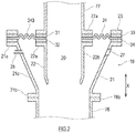
- FIG. 2 is an end view of a cut portion where the expansion pipe joint 10 according to an embodiment of the present invention is cut along a plane passing through a central axis.
- the expansion pipe joint 10 in a state where the vibration pipe 78 is stationary, the expansion pipe joint 10 is a rotating body, and a direction parallel to an extending direction of the axis of rotation of this rotating body is referred to as the "axial direction X" of the expansion pipe joint 10, and an axis of rotation of the rotating body is referred to as the "central axis" of the expansion pipe joint 10.
- the expansion pipe joint 10 is disposed in the pipe system so that the axial direction X and the flow direction of a conveyed object are parallel to each other.
- the expansion pipe joint 10 shown in Fig. 2 is configured with an outer tube 21, an inner tube 22 inserted in the outer tube 21, and a closing member 24 that closes the space between the outer tube 21 and the inner tube 22.
- the inside of the inner tube 22 serves as a conveyance path 20 for a conveyed object in the expansion pipe joint 10.
- the outer tube 21 is a metal cylindrical body extending in the axial direction X, and includes an upper flange 21a provided at the upstream end of the outer tube, a lower flange 21b provided at a downstream end, and a body 21c that connects the upper flange 21a and the lower flange 21b.
- the lower flange 21b of the outer tube 21 is coupled to an inlet flange 78a provided at an upstream end of the vibration pipe 78 with a bolt or the like. Accordingly, the outer tube 21 is displaced integrally with the vibration pipe 78.
- An inner diameter of the upper flange 21a is larger than an inner diameter of the lower flange 21b.
- the body 21c has a tapered shape with a narrowed bottom that smoothly connects the upper flange 21a and the lower flange 21b having different inner diameters as described above.
- a conveyed object can be quickly moved or conveyed from the outer tube 21 to the vibration pipe 78 while a displaceable range in a direction perpendicular to the axial direction X of the outer tube 21 with respect to the inner tube 22 is ensured.
- the inner tube 22 is a metal cylindrical body extending in the axial direction X, and includes an upper flange 22a provided at the upstream end of the inner tube 22 and a body 22b.
- the upper flange 22a of the inner tube 22 is coupled to an outlet flange 77a provided at a downstream end of the fixed pipe 77 with a bolt or the like.
- a position in the axial direction X of the downstream end of the body 22b of the inner tube 22 is slightly upstream of a position in the axial direction X of the lower flange 21b of the outer tube 21.
- An outer diameter of the body 22b of the inner tube 22 is smaller than the inner diameter of the lower flange 21b of the outer tube 21. Accordingly, a gap in a radial direction exists between the inner periphery of the outer tube 21 and the outer periphery of the inner tube 22 inserted substantially concentrically in the outer tube 21.
- the size of the gap is preferably larger than the maximum displacement in the horizontal direction of the outer tube 21 with respect to the inner tube 22 at the downstream end of the inner tube 22 in order to avoid interference between the inner tube 22 and the outer tube 21 at the time of displacement.
- the gap may be an air gap.
- an intrusion prevention member 25 made from a material that can be elastically deformed and/or follows displacement, such as rubber, may be provided in the gap.
- the intrusion prevention member 25 may be provided at the downstream end of the inner tube 22 or in the vicinity of the downstream end, or may be provided on the outer tube 21.
- the intrusion prevention member 25 may be bridged between the downstream end of the inner tube 22 or the vicinity of the downstream end and the inner periphery of the outer tube 21.
- the intrusion prevention member 25 has an annular shape that is continuous or discontinuous in the circumferential direction in plan view, and an inner peripheral edge of the intrusion prevention member 25 is fixed to the downstream end of the inner tube 21.
- Fig. 3 is a view of the closing member 24 as viewed from the axial direction X. As shown in
- the closing member 24 has a hollow disk shape in plan view.
- An inner diameter of the closing member 24 is substantially the same as the inner diameter of the upper flange 22a of the inner tube 22.
- an outer diameter of the closing member 24 is substantially the same as the outer diameter of the upper flange 21a of the outer tube 21.
- the outer diameter of the closing member 24 may be smaller or larger than the outer diameter of the upper flange 21a of the tube 21, as long as the outer diameter is large enough to sandwich an outer edge of the closing member 24 between the upper flange 21a of the outer tube 21 and a fixing ring 23.
- the closing member 24 is provided between the upper flange 21a and the upper flange 22a so as to close the gap between the upper flange 21a provided at the upstream end of the outer tube 21 and the upper flange 22a provided at the upstream end of the inner tube 22.
- the position in the axial direction X of the upper flange 22a of the inner tube 22 and the position in the axial direction X of the upper flange 21a of the outer tube 21 are substantially the same in a state where the vibration pipe 78 is stationary.
- an outer mounting portion 241, an expansion and contraction portion 243, and an inner mounting portion 242 are integrally formed in this order from the outer peripheral side.
- the outer mounting portion 241 is sandwiched between the upper flange 21a of the outer tube 21 and the fixing ring 23 with gaskets 33 and 34 provided between them, and is coupled to the upper flange 21a of the outer tube 21.
- the upper flange 21a, the gaskets 33 and 34, the outer mounting portion 241 of the closing member 24, and the fixing ring 23 are fastened by a fastener, such as a bolt (not shown).
- a fastener such as a bolt (not shown).
- the closing member 24 is formed of a material that is sandwiched between the upper flange 21a and the fixing ring 23 and can be compressed and deformed, such as rubber, the gaskets 33 and 34 may be omitted.
- the inner mounting portion 242 is sandwiched between the upper flange 22a of the inner tube 22 and the outlet flange 77a of the fixed pipe 77 with gaskets 31 and 32 provided between them, and is coupled to the upper flange 22a of the inner tube 22.
- the upper flange 22a, the gaskets 31 and 32, the inner mounting portion 242 of the closing member 24, and the outlet flange 77a are fastened by a fastener, such as a bolt (not shown).
- a fastener such as a bolt (not shown).
- the closing member 24 is formed of a material that is sandwiched between the upper flange 22a and the outlet flange 77a and can be compressed and deformed, such as rubber, the gaskets 31 and 32 may be omitted.
- the expansion and contraction portion 243 expands and contracts to absorb the displacement in the axial direction X and the radial direction of the outer mounting portion 241 relative to the inner mounting portion 242.
- the expansion and contraction portion 243 shown in Fig. 2 is made from rubber, resin, or cloth, and has a bellows formed in the radial direction.
- the expansion and contraction portion 243 is made from a material having heat resistance.
- the shape of the expansion and contraction portion 243 is not limited to the bellows shape.
- a surface material of the expansion and contraction portion 243 of the closing member 24 (24A) is made from rubber or resin having elasticity
- the expansion and contraction portion 243 may be planar.
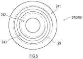
- the expansion and contraction portion 243 of the closing member 24 (24B) may have a spiral core material 29 attached to the surface material made from rubber, resin, or cloth.
- the surface material of the expansion and contraction portion 243 may be bent in the radial direction between the core materials 29 to provide a margin for expansion and contraction.
- the core material 29 may be attached to the surface material in a form, such as a mesh, instead of a spiral.
- the incineration ash treatment facility 7 includes the crusher 75 that is a vibration device for processing incineration ash, a pipe (the fixed pipe 77) that sends the incineration ash to the crusher 75, and the expansion pipe joint 10 provided between the outlet of the pipe and the inlet (the vibration pipe 78) of the crusher 75.
- the expansion pipe joint 10 is the expansion pipe joint 10 that absorbs displacement occurring at the connection portion between the fixed pipe 77 that is the upstream pipe and the vibration pipe 78 that is the downstream pipe, and includes the outer tube 21 that has a downstream end coupled to the vibration pipe 78, the inner tube 22 that is inserted into the outer tube 21 and has an upstream end coupled to the fixed pipe 778, and the closing member 24 having elasticity provided between the upstream end of the outer tube 21 and the upstream end of the inner tube 22 so as to close the gap between them.
- the closing member 24 is in a plane orthogonal to the axial direction X of the expansion pipe joint 10. Furthermore, the closing member 24 is located at the farthest position in the axial direction X from the lower flange 21b of the outer tube 21 forming the downstream end of the expansion pipe joint 10. The closing member 24 and the conveyed object do not contact each other until the conveyed object fills the expansion pipe joint 10. Therefore, contact between the closing member 24 and the conveyed object and friction caused by such contact can be avoided as much as possible.
- the distance in the axial direction X between the closing member 24 and the downstream end of the expansion pipe joint 10 is made larger, so that contact between the conveyed object that overflows from the vibration pipe 78 into the expansion pipe joint 10 and the closing member 24 can be avoided, and physical, chemical, and thermal influences that the closing member 24 receives from the conveyed object can be suppressed.
- physical, chemical, and thermal deterioration of the closing member 24 can be suppressed.
- the position in the axial direction X of the upper flange 22a of the inner tube 22 of the expansion pipe joint 10 and the position in the axial direction X of the upper flange 21a of the outer tube 21 are preferably substantially the same in a state where the vibration pipe 78 is stationary.
- the present invention is not limited to the configuration where the position in the axial direction X of the upper flange 22a of the inner tube 22 and the position in the axial direction X of the upper flange 21a of the outer tube 21 are strictly the same. That is, as shown in Fig.
- a bus line L of the closing member 24 is inclined by ⁇ ° from the axial direction X by a difference between the position in the axial direction X of the upstream end of the outer tube 21 and the position in the axial direction X of the upstream end of the inner tube 22, and, as long as ⁇ ° is within a predetermined range, deterioration of the closing member 24 can be suppressed.
- the bus line L of the closing member 24 can be defined by a straight line connecting an outer peripheral edge of the inner mounting portion 242 and an inner peripheral portion of the outer mounting portion 241 on one main surface (a lower surface in Fig. 6 ) of the closing member 24.
- the range of the inclination ⁇ ° from the axial direction X of the bus line L of the closing member 24 can be determined according to a situation where the expansion pipe joint 10 is installed.
- a dimension H in the axial direction X of the closing member 24 may be about 1/5 of the overall dimension H 0 in a state where the vibration pipe 78 is stationary.
- the overall dimension H 0 in the axial direction X of the expansion pipe joint 10 may be the dimension in the axial direction X from the downstream end of the outer tube 21 to the upstream end (the inner mounting portion 242) of the closing member 24.
- the dimension H in the axial direction X of the closing member 24 may be the dimension in the axial direction X from the downstream end (the outer mounting portion 241) to the upstream end (the inner mounting portion 242) of the closing member 24.
- the expansion pipe joint 10 effectively uses this gap.
- a pipe 28 is connected to a portion between the upstream end and the central portion in the axial direction X of the outer tube 21.
- the pipe 28 can function as a supply pipe that supplies a fluid between the outer tube 21 and the inner tube 22 and/or a discharge pipe that discharges a fluid from between the outer tube 21 and the inner tube 22.
- the pipe 28 is preferably connected to a position close to the upper flange 21a in the body 21c of the outer tube 21.
- the pipe 28 By using the pipe 28 and supplying air between the inner tube 22 and the outer tube 21, the inside of the expansion pipe joint 10 can be pressurized and clogging of the expansion pipe joint 10 can be eliminated. Further, the pipe 28 is used to supply powder or liquid chemical substances (medicine, and the like) between the inner tube 22 and the outer tube 21, so that the conveyed object can also be modified or the environment of the conveyance path 20 can also be changed. Furthermore, the pipe 28 is used to introduce and discharge air between the inner tube 22 and the outer tube 21 and in the vicinity of the closing member 24, so that physical, chemical, and thermal effects that the atmosphere of the closing member 24 has on the closing member 24 can also be suppressed.
- powder or liquid chemical substances medicine, and the like
- an observation window 27 which is one of internal monitoring systems, is provided between the upstream end and the central portion in the axial direction X of the outer tube 21.
- the observation window 27 is fitted with glass having a function (for example, an antistatic function) for preventing adhesion of a conveyed object, dust, and the like.
- the observation window 27 is preferably provided at a position close to the upper flange 21a in the body 21c of the outer tube 21.
- the inside of the expansion pipe joint 10 that has conventionally been a black box can be observed from the outside of the expansion pipe joint 10.
- the degree of wear of the closing member 24 can be checked through the observation window 27 without disassembling the expansion pipe joint 10.
- the internal monitoring system is not limited to the observation window 27 as long as the internal monitoring system allows a state between the outer tube 21 and the inner tube 22 to be observed and monitored.
- a monitoring system such as a camera for capturing an image of the state between the outer tube 21 and the inner tube 22 or a temperature detector, may be provided between the upstream end and the central portion in the axial direction X of the outer tube 21.
- the expansion pipe joint according to the present invention is not limited to the above embodiment, and is widely applicable to an expansion pipe joint that absorbs displacement occurring between connected pipes at a connection portion provided in a location where a conveyed object is conveyed by gravity in a pipe system that conveys powdery and granular conveyed objects.
Landscapes
- Engineering & Computer Science (AREA)
- General Engineering & Computer Science (AREA)
- Mechanical Engineering (AREA)
- Joints Allowing Movement (AREA)
- Gasification And Melting Of Waste (AREA)
Applications Claiming Priority (2)
| Application Number | Priority Date | Filing Date | Title |
|---|---|---|---|
| JP2017071044A JP6863798B2 (ja) | 2017-03-31 | 2017-03-31 | 伸縮管継手及び焼却灰処理設備 |
| PCT/JP2018/011649 WO2018180967A1 (ja) | 2017-03-31 | 2018-03-23 | 伸縮管継手及び焼却灰処理設備 |
Publications (3)
| Publication Number | Publication Date |
|---|---|
| EP3604884A1 true EP3604884A1 (de) | 2020-02-05 |
| EP3604884A4 EP3604884A4 (de) | 2021-01-06 |
| EP3604884B1 EP3604884B1 (de) | 2023-10-11 |
Family
ID=63675678
Family Applications (1)
| Application Number | Title | Priority Date | Filing Date |
|---|---|---|---|
| EP18775850.3A Active EP3604884B1 (de) | 2017-03-31 | 2018-03-23 | Expansionsrohrverbindung und behandlungsanlage für verbrennungsasche |
Country Status (5)
| Country | Link |
|---|---|
| US (1) | US11639763B2 (de) |
| EP (1) | EP3604884B1 (de) |
| JP (1) | JP6863798B2 (de) |
| TW (1) | TWI675164B (de) |
| WO (1) | WO2018180967A1 (de) |
Families Citing this family (2)
| Publication number | Priority date | Publication date | Assignee | Title |
|---|---|---|---|---|
| JP7402086B2 (ja) * | 2020-03-16 | 2023-12-20 | 川崎重工業株式会社 | 伸縮管継手及び焼却灰処理設備 |
| CN113639138A (zh) * | 2021-07-21 | 2021-11-12 | 上海外高桥造船有限公司 | 一种膨胀节保护装置 |
Family Cites Families (24)
| Publication number | Priority date | Publication date | Assignee | Title |
|---|---|---|---|---|
| US1076738A (en) * | 1912-10-29 | 1913-10-28 | Edward F Berry | Dredging device (coupling.) |
| US2419750A (en) * | 1944-11-22 | 1947-04-29 | Boeing Aircraft Co | Flexible duct coupling |
| US3669471A (en) * | 1970-05-19 | 1972-06-13 | Uniroyal Inc | Flexible connecting device |
| IT979709B (it) * | 1972-03-23 | 1974-09-30 | Vulkan Kupplung Getriebe | Giunto cedevole per alberi |
| JPS5671582U (de) * | 1979-11-07 | 1981-06-12 | ||
| JPS5671582A (en) * | 1979-11-19 | 1981-06-15 | Nippon Steel Corp | Consumable gas nozzle for welding |
| US4251354A (en) * | 1979-12-28 | 1981-02-17 | Rotex, Inc. | Screening machine |
| US4627625A (en) * | 1981-04-02 | 1986-12-09 | Dresser Industries, Inc. | Air seal between relatively moveable ducts |
| JPS6060394A (ja) * | 1983-09-14 | 1985-04-06 | バブコツク日立株式会社 | 振動吸収コネクタ |
| US4732413A (en) * | 1985-09-09 | 1988-03-22 | Bachmann Industries, Inc. | Expansion joints |
| JPS62143018U (de) * | 1986-03-03 | 1987-09-09 | ||
| US4804211A (en) * | 1986-09-05 | 1989-02-14 | Dresser-Rand Company | Seal assembly |
| JPS6415029U (de) * | 1987-07-15 | 1989-01-25 | ||
| US5259511A (en) * | 1991-09-27 | 1993-11-09 | Rotex, Inc. | Sliding conduit connector for screening machine |
| US5443290A (en) * | 1993-12-03 | 1995-08-22 | Mid-Atlantic Technical Services Incorporated | Floating ring expansion joint liner seal |
| US5887726A (en) * | 1996-07-30 | 1999-03-30 | Rotex, Inc. | Coupling for connecting feed spout to screening machine |
| US6402203B1 (en) * | 2000-09-15 | 2002-06-11 | Senior Investments Ag | Flange construction for fabric expansion joints |
| KR20040012034A (ko) | 2002-07-31 | 2004-02-11 | 정구증 | 신축 이음관 |
| NL1021920C2 (nl) | 2002-11-14 | 2004-05-17 | Ubbink Nederland Bv | Rookgasafvoerleiding. |
| JP4271518B2 (ja) * | 2003-07-14 | 2009-06-03 | 株式会社タクマ | 振動搬送装置とこれに接続される非振動装置との接続機構、接続方法、振動搬送装置、および溶融前処理設備 |
| JP2005219864A (ja) | 2004-02-05 | 2005-08-18 | Mitsubishi Heavy Ind Ltd | 伸縮継手及びこれを備えた搬送装置 |
| JP2006266756A (ja) * | 2005-03-22 | 2006-10-05 | Sumitomo Chemical Co Ltd | サイトグラス |
| JP5666890B2 (ja) | 2010-11-30 | 2015-02-12 | 株式会社東芝 | 伸縮管継手 |
| DE202013000867U1 (de) | 2013-01-29 | 2014-01-30 | Boa Balg- Und Kompensatoren-Technologie Gmbh | Rohrvorrichtung |
-
2017
- 2017-03-31 JP JP2017071044A patent/JP6863798B2/ja active Active
-
2018
- 2018-03-23 EP EP18775850.3A patent/EP3604884B1/de active Active
- 2018-03-23 WO PCT/JP2018/011649 patent/WO2018180967A1/ja not_active Ceased
- 2018-03-23 US US16/499,471 patent/US11639763B2/en active Active
- 2018-03-30 TW TW107111323A patent/TWI675164B/zh active
Also Published As
| Publication number | Publication date |
|---|---|
| TW201905371A (zh) | 2019-02-01 |
| EP3604884A4 (de) | 2021-01-06 |
| JP2018173117A (ja) | 2018-11-08 |
| US11639763B2 (en) | 2023-05-02 |
| EP3604884B1 (de) | 2023-10-11 |
| TWI675164B (zh) | 2019-10-21 |
| US20200386353A1 (en) | 2020-12-10 |
| JP6863798B2 (ja) | 2021-04-21 |
| WO2018180967A1 (ja) | 2018-10-04 |
Similar Documents
| Publication | Publication Date | Title |
|---|---|---|
| US4199010A (en) | Ceramic lined conduit | |
| US11639763B2 (en) | Expansion pipe joint and incineration ash treatment facility | |
| JP6779009B2 (ja) | ローラジャーナルプロテクタ,粉砕ローラユニット及び粉砕機、並びに、ローラジャーナルプロテクタの保守管理方法 | |
| TW200825000A (en) | Bearing monitoring method | |
| WO2016043167A1 (ja) | 粉体搬送装置及びチャー回収装置 | |
| JP6464312B2 (ja) | ベロー補正装置 | |
| JPH04215860A (ja) | ボールミル粉砕機のシール組立体 | |
| EP1920028B1 (de) | Pyrolysesystem | |
| JP2016098005A (ja) | 固形物供給装置 | |
| TWI767610B (zh) | 伸縮管接頭及焚化灰處理設備 | |
| US8833801B2 (en) | Compensator for connecting pipes for dust-laden flue gas | |
| JP5177955B2 (ja) | 粉粒体排出検出装置及び粉粒体貯蔵設備 | |
| JP4018349B2 (ja) | 軸封装置 | |
| CA2948223C (en) | Gearbox assembly for a charging installation of a metallurgical reactor | |
| CN109046798B (zh) | 一种卧式螺旋筛网离心机的轴密封结构 | |
| WO2022074876A1 (ja) | シュート管の閉塞防止構造 | |
| US20050189721A1 (en) | Seal arrangement | |
| JP6511827B2 (ja) | 竪型粉砕機のローラ軸カバー | |
| JP7714487B2 (ja) | 排出装置、粉砕装置、および粉砕装置の運転方法 | |
| JP2005060021A (ja) | 粉粒体輸送管およびその配設構造 | |
| CN110015467A (zh) | 包装机械及其出料管组件 | |
| Agarwal | Product quality in pneumatic conveying: these suggestions will help flush out current problems and prevent future difficulties down the road |
Legal Events
| Date | Code | Title | Description |
|---|---|---|---|
| STAA | Information on the status of an ep patent application or granted ep patent |
Free format text: STATUS: THE INTERNATIONAL PUBLICATION HAS BEEN MADE |
|
| PUAI | Public reference made under article 153(3) epc to a published international application that has entered the european phase |
Free format text: ORIGINAL CODE: 0009012 |
|
| STAA | Information on the status of an ep patent application or granted ep patent |
Free format text: STATUS: REQUEST FOR EXAMINATION WAS MADE |
|
| 17P | Request for examination filed |
Effective date: 20191008 |
|
| AK | Designated contracting states |
Kind code of ref document: A1 Designated state(s): AL AT BE BG CH CY CZ DE DK EE ES FI FR GB GR HR HU IE IS IT LI LT LU LV MC MK MT NL NO PL PT RO RS SE SI SK SM TR |
|
| AX | Request for extension of the european patent |
Extension state: BA ME |
|
| DAV | Request for validation of the european patent (deleted) | ||
| DAX | Request for extension of the european patent (deleted) | ||
| A4 | Supplementary search report drawn up and despatched |
Effective date: 20201207 |
|
| RIC1 | Information provided on ipc code assigned before grant |
Ipc: F16L 55/00 20060101ALI20201201BHEP Ipc: F16L 55/033 20060101ALN20201201BHEP Ipc: F16L 55/07 20060101ALI20201201BHEP Ipc: F16L 27/107 20060101ALI20201201BHEP Ipc: F16L 27/11 20060101ALI20201201BHEP Ipc: F23J 1/00 20060101ALI20201201BHEP Ipc: F16L 55/24 20060101ALI20201201BHEP Ipc: F16L 27/10 20060101AFI20201201BHEP Ipc: F16L 57/06 20060101ALI20201201BHEP Ipc: F16L 41/00 20060101ALI20201201BHEP |
|
| STAA | Information on the status of an ep patent application or granted ep patent |
Free format text: STATUS: EXAMINATION IS IN PROGRESS |
|
| 17Q | First examination report despatched |
Effective date: 20221011 |
|
| GRAP | Despatch of communication of intention to grant a patent |
Free format text: ORIGINAL CODE: EPIDOSNIGR1 |
|
| STAA | Information on the status of an ep patent application or granted ep patent |
Free format text: STATUS: GRANT OF PATENT IS INTENDED |
|
| RIC1 | Information provided on ipc code assigned before grant |
Ipc: F16L 55/033 20060101ALN20230427BHEP Ipc: F16L 41/00 20060101ALI20230427BHEP Ipc: F16L 27/11 20060101ALI20230427BHEP Ipc: F16L 57/06 20060101ALI20230427BHEP Ipc: F16L 55/07 20060101ALI20230427BHEP Ipc: F16L 27/107 20060101ALI20230427BHEP Ipc: F23J 1/00 20060101ALI20230427BHEP Ipc: F16L 55/24 20060101ALI20230427BHEP Ipc: F16L 55/00 20060101ALI20230427BHEP Ipc: F16L 27/10 20060101AFI20230427BHEP |
|
| INTG | Intention to grant announced |
Effective date: 20230524 |
|
| GRAS | Grant fee paid |
Free format text: ORIGINAL CODE: EPIDOSNIGR3 |
|
| GRAA | (expected) grant |
Free format text: ORIGINAL CODE: 0009210 |
|
| STAA | Information on the status of an ep patent application or granted ep patent |
Free format text: STATUS: THE PATENT HAS BEEN GRANTED |
|
| AK | Designated contracting states |
Kind code of ref document: B1 Designated state(s): AL AT BE BG CH CY CZ DE DK EE ES FI FR GB GR HR HU IE IS IT LI LT LU LV MC MK MT NL NO PL PT RO RS SE SI SK SM TR |
|
| REG | Reference to a national code |
Ref country code: GB Ref legal event code: FG4D |
|
| REG | Reference to a national code |
Ref country code: CH Ref legal event code: EP |
|
| REG | Reference to a national code |
Ref country code: DE Ref legal event code: R096 Ref document number: 602018059214 Country of ref document: DE |
|
| REG | Reference to a national code |
Ref country code: IE Ref legal event code: FG4D |
|
| REG | Reference to a national code |
Ref country code: LT Ref legal event code: MG9D |
|
| REG | Reference to a national code |
Ref country code: NL Ref legal event code: MP Effective date: 20231011 |
|
| REG | Reference to a national code |
Ref country code: AT Ref legal event code: MK05 Ref document number: 1620526 Country of ref document: AT Kind code of ref document: T Effective date: 20231011 |
|
| PG25 | Lapsed in a contracting state [announced via postgrant information from national office to epo] |
Ref country code: NL Free format text: LAPSE BECAUSE OF FAILURE TO SUBMIT A TRANSLATION OF THE DESCRIPTION OR TO PAY THE FEE WITHIN THE PRESCRIBED TIME-LIMIT Effective date: 20231011 |
|
| PG25 | Lapsed in a contracting state [announced via postgrant information from national office to epo] |
Ref country code: GR Free format text: LAPSE BECAUSE OF FAILURE TO SUBMIT A TRANSLATION OF THE DESCRIPTION OR TO PAY THE FEE WITHIN THE PRESCRIBED TIME-LIMIT Effective date: 20240112 |
|
| PG25 | Lapsed in a contracting state [announced via postgrant information from national office to epo] |
Ref country code: IS Free format text: LAPSE BECAUSE OF FAILURE TO SUBMIT A TRANSLATION OF THE DESCRIPTION OR TO PAY THE FEE WITHIN THE PRESCRIBED TIME-LIMIT Effective date: 20240211 |
|
| PG25 | Lapsed in a contracting state [announced via postgrant information from national office to epo] |
Ref country code: LT Free format text: LAPSE BECAUSE OF FAILURE TO SUBMIT A TRANSLATION OF THE DESCRIPTION OR TO PAY THE FEE WITHIN THE PRESCRIBED TIME-LIMIT Effective date: 20231011 |
|
| PG25 | Lapsed in a contracting state [announced via postgrant information from national office to epo] |
Ref country code: AT Free format text: LAPSE BECAUSE OF FAILURE TO SUBMIT A TRANSLATION OF THE DESCRIPTION OR TO PAY THE FEE WITHIN THE PRESCRIBED TIME-LIMIT Effective date: 20231011 |
|
| PG25 | Lapsed in a contracting state [announced via postgrant information from national office to epo] |
Ref country code: ES Free format text: LAPSE BECAUSE OF FAILURE TO SUBMIT A TRANSLATION OF THE DESCRIPTION OR TO PAY THE FEE WITHIN THE PRESCRIBED TIME-LIMIT Effective date: 20231011 |
|
| PG25 | Lapsed in a contracting state [announced via postgrant information from national office to epo] |
Ref country code: LT Free format text: LAPSE BECAUSE OF FAILURE TO SUBMIT A TRANSLATION OF THE DESCRIPTION OR TO PAY THE FEE WITHIN THE PRESCRIBED TIME-LIMIT Effective date: 20231011 Ref country code: IS Free format text: LAPSE BECAUSE OF FAILURE TO SUBMIT A TRANSLATION OF THE DESCRIPTION OR TO PAY THE FEE WITHIN THE PRESCRIBED TIME-LIMIT Effective date: 20240211 Ref country code: GR Free format text: LAPSE BECAUSE OF FAILURE TO SUBMIT A TRANSLATION OF THE DESCRIPTION OR TO PAY THE FEE WITHIN THE PRESCRIBED TIME-LIMIT Effective date: 20240112 Ref country code: ES Free format text: LAPSE BECAUSE OF FAILURE TO SUBMIT A TRANSLATION OF THE DESCRIPTION OR TO PAY THE FEE WITHIN THE PRESCRIBED TIME-LIMIT Effective date: 20231011 Ref country code: BG Free format text: LAPSE BECAUSE OF FAILURE TO SUBMIT A TRANSLATION OF THE DESCRIPTION OR TO PAY THE FEE WITHIN THE PRESCRIBED TIME-LIMIT Effective date: 20240111 Ref country code: AT Free format text: LAPSE BECAUSE OF FAILURE TO SUBMIT A TRANSLATION OF THE DESCRIPTION OR TO PAY THE FEE WITHIN THE PRESCRIBED TIME-LIMIT Effective date: 20231011 Ref country code: PT Free format text: LAPSE BECAUSE OF FAILURE TO SUBMIT A TRANSLATION OF THE DESCRIPTION OR TO PAY THE FEE WITHIN THE PRESCRIBED TIME-LIMIT Effective date: 20240212 |
|
| PG25 | Lapsed in a contracting state [announced via postgrant information from national office to epo] |
Ref country code: SE Free format text: LAPSE BECAUSE OF FAILURE TO SUBMIT A TRANSLATION OF THE DESCRIPTION OR TO PAY THE FEE WITHIN THE PRESCRIBED TIME-LIMIT Effective date: 20231011 Ref country code: RS Free format text: LAPSE BECAUSE OF FAILURE TO SUBMIT A TRANSLATION OF THE DESCRIPTION OR TO PAY THE FEE WITHIN THE PRESCRIBED TIME-LIMIT Effective date: 20231011 Ref country code: PL Free format text: LAPSE BECAUSE OF FAILURE TO SUBMIT A TRANSLATION OF THE DESCRIPTION OR TO PAY THE FEE WITHIN THE PRESCRIBED TIME-LIMIT Effective date: 20231011 Ref country code: NO Free format text: LAPSE BECAUSE OF FAILURE TO SUBMIT A TRANSLATION OF THE DESCRIPTION OR TO PAY THE FEE WITHIN THE PRESCRIBED TIME-LIMIT Effective date: 20240111 Ref country code: LV Free format text: LAPSE BECAUSE OF FAILURE TO SUBMIT A TRANSLATION OF THE DESCRIPTION OR TO PAY THE FEE WITHIN THE PRESCRIBED TIME-LIMIT Effective date: 20231011 Ref country code: HR Free format text: LAPSE BECAUSE OF FAILURE TO SUBMIT A TRANSLATION OF THE DESCRIPTION OR TO PAY THE FEE WITHIN THE PRESCRIBED TIME-LIMIT Effective date: 20231011 |
|
| PG25 | Lapsed in a contracting state [announced via postgrant information from national office to epo] |
Ref country code: DK Free format text: LAPSE BECAUSE OF FAILURE TO SUBMIT A TRANSLATION OF THE DESCRIPTION OR TO PAY THE FEE WITHIN THE PRESCRIBED TIME-LIMIT Effective date: 20231011 |
|
| REG | Reference to a national code |
Ref country code: DE Ref legal event code: R097 Ref document number: 602018059214 Country of ref document: DE |
|
| PG25 | Lapsed in a contracting state [announced via postgrant information from national office to epo] |
Ref country code: CZ Free format text: LAPSE BECAUSE OF FAILURE TO SUBMIT A TRANSLATION OF THE DESCRIPTION OR TO PAY THE FEE WITHIN THE PRESCRIBED TIME-LIMIT Effective date: 20231011 |
|
| PG25 | Lapsed in a contracting state [announced via postgrant information from national office to epo] |
Ref country code: SK Free format text: LAPSE BECAUSE OF FAILURE TO SUBMIT A TRANSLATION OF THE DESCRIPTION OR TO PAY THE FEE WITHIN THE PRESCRIBED TIME-LIMIT Effective date: 20231011 |
|
| PG25 | Lapsed in a contracting state [announced via postgrant information from national office to epo] |
Ref country code: SM Free format text: LAPSE BECAUSE OF FAILURE TO SUBMIT A TRANSLATION OF THE DESCRIPTION OR TO PAY THE FEE WITHIN THE PRESCRIBED TIME-LIMIT Effective date: 20231011 Ref country code: SK Free format text: LAPSE BECAUSE OF FAILURE TO SUBMIT A TRANSLATION OF THE DESCRIPTION OR TO PAY THE FEE WITHIN THE PRESCRIBED TIME-LIMIT Effective date: 20231011 Ref country code: RO Free format text: LAPSE BECAUSE OF FAILURE TO SUBMIT A TRANSLATION OF THE DESCRIPTION OR TO PAY THE FEE WITHIN THE PRESCRIBED TIME-LIMIT Effective date: 20231011 Ref country code: EE Free format text: LAPSE BECAUSE OF FAILURE TO SUBMIT A TRANSLATION OF THE DESCRIPTION OR TO PAY THE FEE WITHIN THE PRESCRIBED TIME-LIMIT Effective date: 20231011 Ref country code: DK Free format text: LAPSE BECAUSE OF FAILURE TO SUBMIT A TRANSLATION OF THE DESCRIPTION OR TO PAY THE FEE WITHIN THE PRESCRIBED TIME-LIMIT Effective date: 20231011 Ref country code: CZ Free format text: LAPSE BECAUSE OF FAILURE TO SUBMIT A TRANSLATION OF THE DESCRIPTION OR TO PAY THE FEE WITHIN THE PRESCRIBED TIME-LIMIT Effective date: 20231011 |
|
| PLBE | No opposition filed within time limit |
Free format text: ORIGINAL CODE: 0009261 |
|
| STAA | Information on the status of an ep patent application or granted ep patent |
Free format text: STATUS: NO OPPOSITION FILED WITHIN TIME LIMIT |
|
| 26N | No opposition filed |
Effective date: 20240712 |
|
| REG | Reference to a national code |
Ref country code: DE Ref legal event code: R119 Ref document number: 602018059214 Country of ref document: DE |
|
| PG25 | Lapsed in a contracting state [announced via postgrant information from national office to epo] |
Ref country code: SI Free format text: LAPSE BECAUSE OF FAILURE TO SUBMIT A TRANSLATION OF THE DESCRIPTION OR TO PAY THE FEE WITHIN THE PRESCRIBED TIME-LIMIT Effective date: 20231011 |
|
| PG25 | Lapsed in a contracting state [announced via postgrant information from national office to epo] |
Ref country code: SI Free format text: LAPSE BECAUSE OF FAILURE TO SUBMIT A TRANSLATION OF THE DESCRIPTION OR TO PAY THE FEE WITHIN THE PRESCRIBED TIME-LIMIT Effective date: 20231011 |
|
| REG | Reference to a national code |
Ref country code: CH Ref legal event code: PL |
|
| PG25 | Lapsed in a contracting state [announced via postgrant information from national office to epo] |
Ref country code: LU Free format text: LAPSE BECAUSE OF NON-PAYMENT OF DUE FEES Effective date: 20240323 |
|
| PG25 | Lapsed in a contracting state [announced via postgrant information from national office to epo] |
Ref country code: MC Free format text: LAPSE BECAUSE OF FAILURE TO SUBMIT A TRANSLATION OF THE DESCRIPTION OR TO PAY THE FEE WITHIN THE PRESCRIBED TIME-LIMIT Effective date: 20231011 |
|
| GBPC | Gb: european patent ceased through non-payment of renewal fee |
Effective date: 20240323 |
|
| PG25 | Lapsed in a contracting state [announced via postgrant information from national office to epo] |
Ref country code: MC Free format text: LAPSE BECAUSE OF FAILURE TO SUBMIT A TRANSLATION OF THE DESCRIPTION OR TO PAY THE FEE WITHIN THE PRESCRIBED TIME-LIMIT Effective date: 20231011 Ref country code: LU Free format text: LAPSE BECAUSE OF NON-PAYMENT OF DUE FEES Effective date: 20240323 |
|
| REG | Reference to a national code |
Ref country code: BE Ref legal event code: MM Effective date: 20240331 |
|
| PG25 | Lapsed in a contracting state [announced via postgrant information from national office to epo] |
Ref country code: DE Free format text: LAPSE BECAUSE OF NON-PAYMENT OF DUE FEES Effective date: 20241001 |
|
| PG25 | Lapsed in a contracting state [announced via postgrant information from national office to epo] |
Ref country code: BE Free format text: LAPSE BECAUSE OF NON-PAYMENT OF DUE FEES Effective date: 20240331 |
|
| PG25 | Lapsed in a contracting state [announced via postgrant information from national office to epo] |
Ref country code: GB Free format text: LAPSE BECAUSE OF NON-PAYMENT OF DUE FEES Effective date: 20240323 |
|
| PG25 | Lapsed in a contracting state [announced via postgrant information from national office to epo] |
Ref country code: FR Free format text: LAPSE BECAUSE OF NON-PAYMENT OF DUE FEES Effective date: 20240331 |
|
| PG25 | Lapsed in a contracting state [announced via postgrant information from national office to epo] |
Ref country code: IE Free format text: LAPSE BECAUSE OF NON-PAYMENT OF DUE FEES Effective date: 20240323 |
|
| PG25 | Lapsed in a contracting state [announced via postgrant information from national office to epo] |
Ref country code: IE Free format text: LAPSE BECAUSE OF NON-PAYMENT OF DUE FEES Effective date: 20240323 Ref country code: GB Free format text: LAPSE BECAUSE OF NON-PAYMENT OF DUE FEES Effective date: 20240323 Ref country code: FR Free format text: LAPSE BECAUSE OF NON-PAYMENT OF DUE FEES Effective date: 20240331 Ref country code: DE Free format text: LAPSE BECAUSE OF NON-PAYMENT OF DUE FEES Effective date: 20241001 Ref country code: BE Free format text: LAPSE BECAUSE OF NON-PAYMENT OF DUE FEES Effective date: 20240331 Ref country code: CH Free format text: LAPSE BECAUSE OF NON-PAYMENT OF DUE FEES Effective date: 20240331 |
|
| PG25 | Lapsed in a contracting state [announced via postgrant information from national office to epo] |
Ref country code: CY Free format text: LAPSE BECAUSE OF FAILURE TO SUBMIT A TRANSLATION OF THE DESCRIPTION OR TO PAY THE FEE WITHIN THE PRESCRIBED TIME-LIMIT; INVALID AB INITIO Effective date: 20180323 |
|
| PG25 | Lapsed in a contracting state [announced via postgrant information from national office to epo] |
Ref country code: HU Free format text: LAPSE BECAUSE OF FAILURE TO SUBMIT A TRANSLATION OF THE DESCRIPTION OR TO PAY THE FEE WITHIN THE PRESCRIBED TIME-LIMIT; INVALID AB INITIO Effective date: 20180323 |
|
| PG25 | Lapsed in a contracting state [announced via postgrant information from national office to epo] |
Ref country code: FI Free format text: LAPSE BECAUSE OF FAILURE TO SUBMIT A TRANSLATION OF THE DESCRIPTION OR TO PAY THE FEE WITHIN THE PRESCRIBED TIME-LIMIT Effective date: 20231011 |
|
| PG25 | Lapsed in a contracting state [announced via postgrant information from national office to epo] |
Ref country code: TR Free format text: LAPSE BECAUSE OF FAILURE TO SUBMIT A TRANSLATION OF THE DESCRIPTION OR TO PAY THE FEE WITHIN THE PRESCRIBED TIME-LIMIT Effective date: 20231011 |
|
| PGFP | Annual fee paid to national office [announced via postgrant information from national office to epo] |
Ref country code: IT Payment date: 20260220 Year of fee payment: 9 |