EP3604730A1 - Ausziehleiter, system und verfahren - Google Patents
Ausziehleiter, system und verfahren Download PDFInfo
- Publication number
- EP3604730A1 EP3604730A1 EP19189209.0A EP19189209A EP3604730A1 EP 3604730 A1 EP3604730 A1 EP 3604730A1 EP 19189209 A EP19189209 A EP 19189209A EP 3604730 A1 EP3604730 A1 EP 3604730A1
- Authority
- EP
- European Patent Office
- Prior art keywords
- fly
- base
- section
- rail
- flange
- Prior art date
- Legal status (The legal status is an assumption and is not a legal conclusion. Google has not performed a legal analysis and makes no representation as to the accuracy of the status listed.)
- Granted
Links
Images


Classifications
-
- E—FIXED CONSTRUCTIONS
- E06—DOORS, WINDOWS, SHUTTERS, OR ROLLER BLINDS IN GENERAL; LADDERS
- E06C—LADDERS
- E06C1/00—Ladders in general
- E06C1/02—Ladders in general with rigid longitudinal member or members
- E06C1/04—Ladders for resting against objects, e.g. walls poles, trees
- E06C1/08—Ladders for resting against objects, e.g. walls poles, trees multi-part
- E06C1/12—Ladders for resting against objects, e.g. walls poles, trees multi-part extensible, e.g. telescopic
-
- E—FIXED CONSTRUCTIONS
- E06—DOORS, WINDOWS, SHUTTERS, OR ROLLER BLINDS IN GENERAL; LADDERS
- E06C—LADDERS
- E06C7/00—Component parts, supporting parts, or accessories
- E06C7/06—Securing devices or hooks for parts of extensible ladders
-
- E—FIXED CONSTRUCTIONS
- E06—DOORS, WINDOWS, SHUTTERS, OR ROLLER BLINDS IN GENERAL; LADDERS
- E06C—LADDERS
- E06C7/00—Component parts, supporting parts, or accessories
- E06C7/08—Special construction of longitudinal members, or rungs or other treads
-
- E—FIXED CONSTRUCTIONS
- E06—DOORS, WINDOWS, SHUTTERS, OR ROLLER BLINDS IN GENERAL; LADDERS
- E06C—LADDERS
- E06C7/00—Component parts, supporting parts, or accessories
- E06C7/08—Special construction of longitudinal members, or rungs or other treads
- E06C7/082—Connections between rungs or treads and longitudinal members
- E06C7/084—Rungs comprising projecting tabs or flanges
-
- E—FIXED CONSTRUCTIONS
- E06—DOORS, WINDOWS, SHUTTERS, OR ROLLER BLINDS IN GENERAL; LADDERS
- E06C—LADDERS
- E06C7/00—Component parts, supporting parts, or accessories
- E06C7/50—Joints or other connecting parts
Definitions
- the present invention relates to an extension ladder having a fly section whose rails are nested in rails of a rail section.
- references to the "present invention” or “invention” relate to exemplary embodiments and not necessarily to every embodiment encompassed by the appended claims.
- references to the "present invention” or “invention” relate to exemplary embodiments and not necessarily to every embodiment encompassed by the appended claims.
- the present invention relates to an extension ladder having a fly section whose rails are nested in rails of a base section where the rails of the base section have stems to position and guide the rails of the fly section as they move relative to the rails of the base section.
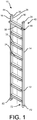
- Extension ladders provide the convenience of having a base section and a fly section attached to the outside of the base section which moves relative to the base section to extend the effective length of the extension ladder to reach variable heights.
- the fly section is stacked on the base section, which requires essentially a volume which is the length of the fly section aligned with and on the base section and a width that is the width of the rail of the base section and the width of the rail of the fly section.
- There may be instances for storage purposes where it is difficult to fit the extension ladder into a place that is out of the way because of its width.
- the number of extension ladders that are placed alongside and on each other is limited by the overall width available to house the ladders together, such as in a cargo area of a truck.
- the present invention pertains to an extension ladder.
- the ladder comprises a base section having a right base rail and a left base rail in parallel and spaced relation with the right base rail.
- the right base rail having a C-shaped cross-section formed by a right base flange attached to a base web and a left base flange attached to the base web with the base web disposed between the right base flange and the left base flange.
- the base section having base rungs attached to the right and left base rails and disposed in front of and outside of the right base flange of the right base rail.
- the ladder comprises a fly section having a right fly rail and a left fly rail in parallel and spaced relation with the right fly rail.
- the fly section having fly rungs attached to and extending in between the right and left fly rails.
- the right base flange and the left base flange disposed about the right fly rail with the right fly rail disposed in between the right and left base flanges.
- the fly section nested in the base section and configured for at least a portion of the fly section to slide up above the base section and for the fly section to slide back down relative to the base section while remaining engaged with the base section through the right and left base rails disposed about the right and left fly rails, respectively.
- the right fly rail formed by a right fly flange attached to a fly web and a left fly flange attached to the fly web with the fly web disposed between the right fly flange and the left fly flange.
- the right fly rail having a top and a bottom. The top is part of the portion that is configured to slide up above the base section.
- the ladder comprises a cap attached to the top. The cap having a surface which extends between the right fly flange and the fly web and the left fly flange.
- the ladder comprises a locking mechanism to fix and lock the fly section to the base section at a desired position relative to the base section.
- the present invention pertains to a method of positioning an extension ladder.
- the method comprises the steps of moving the extension ladder to a desired location. There is the step of sliding a fly section of the extension ladder relative to a base section of the extension ladder to a desired length. There is the step of leaning the extension ladder against an object.
- the base section having a right base rail and a left base rail in parallel and spaced relation with the right base rail.
- the right base rail having a C-shaped cross-section formed by a right base flange attached to a base web and a left base flange attached to the base web with the base web disposed between the right base flange and the left base flange.
- the base section having base rungs attached to the right and left base rails and disposed in front of and outside of the right base flange of the right base rail.
- the fly section having a right fly rail and a left fly rail in parallel and spaced relation with the right fly rail.
- the fly section having fly rungs attached to and extending in between the right and left fly rails.
- the right base flange and the left base flange disposed about the right fly rail with the right fly rail disposed in between the right and left base flanges.
- the fly section nested in the base section and configured for at least a portion of the fly section to slide up above the base section and for the fly section to slide back down relative to the base section while remaining engaged with the base section through the right and left base rails disposed about the right and left fly rails, respectively.
- the right fly rail formed by a right fly flange attached to a fly web and a left fly flange attached to the fly web with the fly web disposed between the right fly flange and the left fly flange.
- the right fly rail having a top and a bottom. The top is part of the portion that is configured to slide up above the base section.
- the ladder comprises a cap attached to the top.
- the cap having a surface which extends between the right fly flange and the fly web and the left fly flange.
- the ladder comprises a locking mechanism to fix and lock the fly section to the base section at a desired position relative to the base section.
- the ladder 10 comprises a base section 12 having a right base rail 14 and a left base rail 16 in parallel and spaced relation with the right base rail 14.
- the right base rail 14 having a C-shaped cross-section formed by a right base flange 18 attached to a base web 20 and a left base flange 22 attached to the base web 20 with the base web 20 disposed between the right base flange 18 and the left base flange 22, as shown in figure 20 .
- the base section 12 having base rungs 24 attached to the right and left base rails 14, 16 and disposed in front of and outside of the right base flange 18 of the right base rail 14.
- the ladder 10 comprises a fly section 26 having a right fly rail 28 and a left fly rail 30 in parallel and spaced relation with the right fly rail 28.
- the fly section 26 having fly rungs 32 attached to and extending in between the right and left fly rails 28, 30.
- the right base flange 18 and the left base flange 22 disposed about the right fly rail 28 with the right fly rail 28 disposed in between the right and left base flanges 18, 22.
- the fly section 26 nested in the base section 12 and configured for at least a portion of the fly section 26 to slide up above the base section 12 and for the fly section 26 to slide back down relative to the base section 12 while remaining engaged with the base section 12 through the right and left base rails 14, 16 disposed about the right and left fly rails 28, 30, respectively.
- the right fly rail 28 formed by a right fly flange 34 attached to a fly web 36 and a left fly flange 38 attached to the fly web 36 with the fly web 36 disposed between the right fly flange 34 and the left fly flange 38, as shown in figures 21 and 22 .
- the right fly rail 28 having a top 40 and a bottom 42.
- the top 40 is part of the portion that is configured to slide up above the base section 12.
- the base rails and the fly rails may be made of aluminum or fiberglass. Preferably, the base rails and the fly rails or straight.
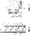
- the fly section 26 may be nested in at least two ways. In one way, the fly web 36 is adjacent and alongside the base web 20 when the right fly flange 34 and left fly flange 38 extend outward from the fly web 36 away from the center line 50 of the extension ladder 10, as shown in figures 11 and 12 . In another way, the fly web 36 is spaced apart from the base web 20 when the right fly flange 34 and left fly flange 38 extend inward from the fly web 36 toward the center line 50 of the extension ladder 10, as shown in figures 9 and 10 .
- the ladder 10 comprises a cap 44, as shown in figure 17A and 17B , attached to the top 40 with no object attached to the cap 44 above the cap 44.
- the cap 44 having a surface 46 which extends between the right fly flange 34 and the fly web 36 and the left fly flange 38.
- the ladder 10 comprises a locking mechanism 48 to fix and lock the fly section 26 to the base section 12 at a desired position relative to the base section 12.
- the extension ladder 10 can support at least 300 lbs. and has a duty rating of at least 1A.
- the right base rail 14 may have a right stem 52 extending inwards from the right base flange 18 toward the left base flange 22, and has a left stem 54 extending inwards from the left base flange 22 toward the right base flange 18, as shown in figures 6 , 8 , 10 , 12 and 20 .
- the right and left stems 52, 54 position the right fly rail 28 in between the right and left rail base flanges a desired distance and act as guides for the right fly rail 28 as the right fly rail 28 moves relative to the right base rail 14, and to position the right fly rail 34 away from rivet upsets.
- the stems additionally serve to strengthen the right base rail 14 and add buttressing and stiffness to the right base rail 14.
- the stems extend along the length of the right base rail 14.
- the stems may be additional stems 56, such as one additional stem 56 in spaced relation and in parallel with the right stem 52 and also with the left stem 54 to further act as guides for the right fly rail 28 as the right fly rail 28 moves relative to the right base rail 14.
- the stems serve to tighten the tolerances between the right fly rail 28 and right base rail 14.
- the left base rail 16 may have stems, same as the right base rail 14 for the same purpose and function.
- the stems may be between .1 and .2 inches long and about .1 inches wide.
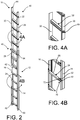
- a first base rung 58 of the base rungs 24 may have a first flattened end 60 that conforms with and fits against and contacts and is in parallel with the right base flange 18 of the right base rail 14, as shown in figures 5 , 7 , 9 and 11 .
- the base section 12 may have at least a first fastener 62, such as a rivet, which extends through the first flattened end 60 and the right base flange 18 to fasten the first flattened end 60 to the right base flange 18.
- the first base rung 58 may have a second flattened end 64 that is fastened to the left base rail 16 with a second fastener 66.
- the first base rung 58 may have a step portion 68 which is flat and extends between the first and second flattened ends 60, 64.
- the flat step portion 68 may be essentially perpendicularly oriented to the first and second flattened ends 60, 64.
- the first base rung 58 may have a first tapered portion 70 which has a slope 72 that extends inwards between the step portion 68 and the first flattened end 60, and may have a second tapered portion 74 which has a slope 72 that extends inwards between the step portion 68 and the second flattened end 64.
- the flattened ends and their tapered portions are formed by crimping, with the tapered portions having a slope 72 of between 20 degrees and 65 degrees and preferably about 45 degrees.
- the tapered portion begins about 1.5 inches to about 3 inches from the inner edge of the right base flange 18, and the same for the left side of the rung.
- the fly rungs 32 may be swaged to the fly webs 36 of the first and second fly rails and form a swage joint 69, as shown in figure 4A .
- the rungs may be hollow and have a step portion 68 which has grooves or serrations to provide for traction when a user places a foot on the stepping surface 46 of a fly rung.
- the cap 44 may have an attachment portion 76 that is disposed between and extends along the fly web 36 and the right fly flange 34 and the left fly flange 38, and a ceiling portion 78 attached to and extending from and above the attachment portion 76, as shown in figures 17A and 17B .
- the ceiling portion 78 having a solid surface 46 and a perimeter that defines a ridge that extends along and on the top 40 of the right fly rail 28 in contact and on the fly web 36 and the right fly flange 34 and the left fly flange 38.
- the ceiling portion 78 may extend upward in an arc shape.
- the ceiling portion 78 may have ribs 80 disposed on the solid surface 46.
- each base rail upon which the extension ladder 10 rests on ground when the extension ladder 10 is leaning against an object either is the bare rail itself or has a foot 82 on the bottom 42.
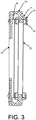
- the locking mechanism 48 may be a J-lock 84 that extends from a side of a J-lock rung 25 of the base section 12 and back through a lock hole 71 in the right base rail 14 and into a rung 32 of the fly section 26 through an end of the rung, which is hollow, to lock the fly section 26 and the base section 12 together, as shown in figure 3 .
- the fly section 26 and the base section 12 are configured to be in a locked position so their rungs are alongside each other, so the portions of the fly section 26 and base section 12 which overlap have their steps in line so the foot of a user fits on and steps on the rung of the base section 12 and with the aligned adjacent rung of the fly section 26.
- the fly section 26 is configured to slide relative to the base section 12 when the J-lock 84 is pulled out from the rung of the fly section 26.
- the J-lock rung 25 from which the J-lock 84 extends may have a squared or flat face 86 instead of a crimped end.
- the J-lock 84 fits in and extends from the flat face 86, as shown in figures 3 , 13 and 15 .
- the locking mechanism 48 may be a swing lock 88 that is attached to the right fly flange 34 and the left fly flange 38 of the right base rail 14 and which encompasses a rung of the base section 12 and an adjoining rung of the fly section 26 at a desired position of the fly section 26 relative to the base section 12, as shown in figures 14 and 16 .
- the right fly rail 28 may have a wall 90 attached to the right fly flange 34 and the left fly flange 38 and extending between the right fly flange 34 and the left fly flange 38 and in parallel and spaced relation to the fly web 36, as shown in figures 5-8 .
- the fly web 36 and the wall 90 and the right and left fly flanges 34, 38 forming a cross sectional shape of a rectangle with the wall 90 closing the C cross-section. This is another way the fly section 26 may be nested within the base section 12, where the right fly rail 28 is nested in the right base rail 14.
- Figures 5 and 6 show this embodiment with J-locks 84, where the fly rungs 32 have a hollow rectangular cross-section which corresponds to the cross-section of the J lock that fits into the fly rung.
- Figures 7 and 8 show this embodiment with swing locks 88, where the fly rungs 32 have a D-shaped cross-section, with the step portion 68 of the fly rung having a slight angle downwards to better receive a foot of a user when the user places a foot on the fly rung.
- Figure 13 shows a C-shaped cross-section of a base rail over a rectangular or box shaped cross-section of a fly rail with J-locks 84.
- Figure 14 shows a C-shaped cross-section of a base rail over a rectangular or box cross-section of a fly rail with swing locks 88.
- Figure 15 shows a C-shaped cross-section of a base rail over a C-shaped cross-section of a fly rail with J-locks 84.
- Figure 16 shows a C-shaped cross-section of a base rail over a C-shaped cross-section of a fly rail with swing locks 88.
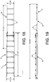
- Figure 18 is an overhead view of the extension ladder 10 at maximum extension.
- Figure 19 is a side view of the extension ladder 10 at maximum extension.
- Figure 20 shows a typical base rail profile.
- Figure 21 shows a typical profile of C-shaped fly rail.
- Figure 22 shows a typical profile of a rectangular shaped fly rail.
- the present invention pertains to a method of positioning an extension ladder 10.
- the method comprises the steps of moving the extension ladder 10 to a desired location. There is the step of sliding a fly section 26 of the extension ladder 10 relative to a base section 12 of the extension ladder 10 to a desired length. There is the step of leaning the extension ladder 10 against an object.
- the base section 12 having a right base rail 14 and a left base rail 16 in parallel and spaced relation with the right base rail 14.
- the right base rail 14 having a C-shaped cross-section formed by a right base flange 18 attached to a base web 20 and a left base flange 22 attached to the base web 20 with the base web 20 disposed between the right base flange 18 and the left base flange 22.
- the base section 12 having base rungs 24 attached to the right and left base rails 14, 16 and disposed in front of and outside of the right base flange 18 of the right base rail 14.
- the fly section 26 having a right fly rail 28 and a left fly rail 30 in parallel and spaced relation with the right fly rail 28.
- the fly section 26 having fly rungs 32 attached to and extending in between the right and left fly rails 28, 30.
- the right base flange 18 and the left base flange 22 disposed about the right fly rail 28 with the right fly rail 28 disposed in between the right and left base flanges 18, 22.
- the fly section 26 nested in the base section 12 and configured for at least a portion of the fly section 26 to slide up above the base section 12 and for the fly section 26 to slide back down relative to the base section 12 while remaining engaged with the base section 12 through the right and left base rails 14, 16 disposed about the right and left fly rails 28, 30, respectively.
- the right fly rail 28 formed by a right fly flange 34 attached to a fly web 36 and a left fly flange 38 attached to the fly web 36 with the fly web 36 disposed between the right fly flange 34 and the left fly flange 38.
- the right fly rail 28 having a top 40 and a bottom 42.
- the top 40 is part of the portion that is configured to slide up above the base section 12.
- the ladder 10 comprises a cap 44 attached to the top 40 with no object attached above the cap 44.
- the cap 44 having a surface 46 which extends between the right fly flange 34 and the fly web 36 and the left fly flange 38.
- the ladder 10 comprises a locking mechanism 48 to fix and lock the fly section 26 to the base section 12 at a desired position relative to the base section 12.
- the fly section 26 has a standard rung design which gives a wide, comfortable standing surface 46 when climbing at height.
- the base section 12 has rungs with flattened ends which are riveted to the outside of the front flange of the rail. This construction allows the fly to move freely within the base section 12 as the fly is extended or retracted.
- the fly and base sections 12 can be held in position relative to each other by the use of J-locks 84, the use of conventional extension ladder rung locks, or other latching mechanisms.
- Conventional extension ladders have the rail sections stacked on top of each other.
- the height of the extension ladders stacked on top of each other is defined as a stack height.
- the smaller stack height 92 of extension ladders 10 stacked on top of each other, as shown in figures 23 and 24 permits a higher product density in palletization and containerization which will reduce shipping cost.
- a first extension ladder having a second extension ladder placed on top of the first extension ladder or alongside the first extension ladder has a stack height 92 1/3 less than the stack height of a first conventional extension ladder having a second conventional extension ladder placed on top of the first conventional extension ladder or alongside the first extension ladder, where the conventional extension ladder has the fly section 26 alongside the base section 12 but not nested in the base section 12.
- the stack height would be the height of at least the width of four rails, the width of the base and fly rails of a first conventional extension ladder plus the width of the base and fly rails of the second conventional ladder on top of the first conventional ladder.
- the stack height is about the width of the base rail 14 of the first extension ladder 10 plus the width of the base rail 14 of the second extension ladder 10 on top of the first extension ladder 10.
Landscapes
- Engineering & Computer Science (AREA)
- Mechanical Engineering (AREA)
- Ladders (AREA)
- Programmable Controllers (AREA)
Priority Applications (1)
| Application Number | Priority Date | Filing Date | Title |
|---|---|---|---|
| EP23206812.2A EP4293190A1 (de) | 2018-08-02 | 2019-07-30 | Ausziehleiter, system und verfahren |
Applications Claiming Priority (1)
| Application Number | Priority Date | Filing Date | Title |
|---|---|---|---|
| US16/053,407 US20200040656A1 (en) | 2018-08-02 | 2018-08-02 | Extension Ladder, System and Method |
Related Child Applications (1)
| Application Number | Title | Priority Date | Filing Date |
|---|---|---|---|
| EP23206812.2A Division EP4293190A1 (de) | 2018-08-02 | 2019-07-30 | Ausziehleiter, system und verfahren |
Publications (2)
| Publication Number | Publication Date |
|---|---|
| EP3604730A1 true EP3604730A1 (de) | 2020-02-05 |
| EP3604730B1 EP3604730B1 (de) | 2023-11-01 |
Family
ID=67513429
Family Applications (2)
| Application Number | Title | Priority Date | Filing Date |
|---|---|---|---|
| EP19189209.0A Active EP3604730B1 (de) | 2018-08-02 | 2019-07-30 | Ausziehleiter, system und verfahren |
| EP23206812.2A Withdrawn EP4293190A1 (de) | 2018-08-02 | 2019-07-30 | Ausziehleiter, system und verfahren |
Family Applications After (1)
| Application Number | Title | Priority Date | Filing Date |
|---|---|---|---|
| EP23206812.2A Withdrawn EP4293190A1 (de) | 2018-08-02 | 2019-07-30 | Ausziehleiter, system und verfahren |
Country Status (6)
| Country | Link |
|---|---|
| US (1) | US20200040656A1 (de) |
| EP (2) | EP3604730B1 (de) |
| CN (1) | CN110792388A (de) |
| AU (3) | AU2019205968A1 (de) |
| CA (1) | CA3050659C (de) |
| MX (1) | MX2019009025A (de) |
Cited By (2)
| Publication number | Priority date | Publication date | Assignee | Title |
|---|---|---|---|---|
| US20220120137A1 (en) * | 2017-05-10 | 2022-04-21 | Werner Co. | Ceiling Ladder, Deep Step and Method |
| US12110742B2 (en) | 2016-12-14 | 2024-10-08 | Werner Co. | Ladder with wide rung |
Families Citing this family (7)
| Publication number | Priority date | Publication date | Assignee | Title |
|---|---|---|---|---|
| CN205713939U (zh) * | 2016-05-03 | 2016-11-23 | 厦门新技术集成有限公司 | 一种伸缩梯子的伸缩腿 |
| CN113187375A (zh) | 2016-10-05 | 2021-07-30 | 伟英企业有限公司 | 梯子、用于梯子的机构和部件以及相关方法 |
| US11034420B2 (en) * | 2019-02-13 | 2021-06-15 | Ross Hoffmann | Rescue ladder attachment |
| US20200370372A1 (en) * | 2019-02-13 | 2020-11-26 | Ross Hoffmann | Rescue ladder attachment |
| US20200256125A1 (en) * | 2019-02-13 | 2020-08-13 | Ross Hoffmann | Rescue ladder attachment |
| CA3126531C (en) * | 2020-07-30 | 2023-12-12 | Werner Co. | Climbing product having an extendable section lock assembly, and methods for using and producing a climbing product |
| CN112576996B (zh) * | 2021-02-24 | 2021-05-25 | 赣通通信股份有限公司 | 用于市政监测的智慧灯杆 |
Citations (6)
| Publication number | Priority date | Publication date | Assignee | Title |
|---|---|---|---|---|
| JPS5022Y1 (de) * | 1969-02-22 | 1975-01-06 | ||
| DE3446255A1 (de) * | 1984-12-19 | 1986-06-19 | Nikolaus Adalbert 7730 Villingen-Schwenningen Kümmerlin | Leiter |
| DE4403001A1 (de) * | 1993-02-01 | 1994-08-04 | Ryu Hoi Kwan | Vorrichtung zum Einstellen der relativen Höhe einer Leiter |
| US5758745A (en) * | 1996-07-18 | 1998-06-02 | Werner Co. | Extension ladder, combination end cap/guide bracket, and method for climbing |
| FR2813918A1 (fr) * | 2000-09-14 | 2002-03-15 | Centaure | Echelle transformable a plusieurs plans |
| JP2015227553A (ja) * | 2014-05-30 | 2015-12-17 | 紀美代 中尾 | 三連伸縮梯子 |
Family Cites Families (8)
| Publication number | Priority date | Publication date | Assignee | Title |
|---|---|---|---|---|
| DE2001416C3 (de) * | 1970-01-14 | 1979-02-08 | Walter 7120 Bissingen Kuemmerlin | Leiter |
| US4182431A (en) * | 1978-03-13 | 1980-01-08 | Little Giant Industries Inc. | Combination extension and step ladder rungs therefor |
| JPS593112Y2 (ja) * | 1980-01-28 | 1984-01-27 | 井上鉄工株式会社 | 伸縮梯子 |
| US5738186A (en) * | 1994-03-01 | 1998-04-14 | Foxdale Developments Limited | Extensible ladder |
| CN2782905Y (zh) * | 2005-03-24 | 2006-05-24 | 苏州市金安通讯设备有限公司 | 轻便绝缘梯 |
| CN205713939U (zh) * | 2016-05-03 | 2016-11-23 | 厦门新技术集成有限公司 | 一种伸缩梯子的伸缩腿 |
| US11486199B2 (en) * | 2016-12-28 | 2022-11-01 | Werner Co. | Ladder, end cap and method |
| US11851949B2 (en) * | 2018-01-30 | 2023-12-26 | Werner Co. | Multipurpose ladder and method |
-
2018
- 2018-08-02 US US16/053,407 patent/US20200040656A1/en not_active Abandoned
-
2019
- 2019-07-15 AU AU2019205968A patent/AU2019205968A1/en not_active Abandoned
- 2019-07-26 CA CA3050659A patent/CA3050659C/en active Active
- 2019-07-30 CN CN201910695399.2A patent/CN110792388A/zh active Pending
- 2019-07-30 EP EP19189209.0A patent/EP3604730B1/de active Active
- 2019-07-30 MX MX2019009025A patent/MX2019009025A/es unknown
- 2019-07-30 EP EP23206812.2A patent/EP4293190A1/de not_active Withdrawn
-
2021
- 2021-04-23 AU AU2021202533A patent/AU2021202533C1/en not_active Ceased
-
2023
- 2023-07-06 AU AU2023204349A patent/AU2023204349A1/en not_active Abandoned
Patent Citations (6)
| Publication number | Priority date | Publication date | Assignee | Title |
|---|---|---|---|---|
| JPS5022Y1 (de) * | 1969-02-22 | 1975-01-06 | ||
| DE3446255A1 (de) * | 1984-12-19 | 1986-06-19 | Nikolaus Adalbert 7730 Villingen-Schwenningen Kümmerlin | Leiter |
| DE4403001A1 (de) * | 1993-02-01 | 1994-08-04 | Ryu Hoi Kwan | Vorrichtung zum Einstellen der relativen Höhe einer Leiter |
| US5758745A (en) * | 1996-07-18 | 1998-06-02 | Werner Co. | Extension ladder, combination end cap/guide bracket, and method for climbing |
| FR2813918A1 (fr) * | 2000-09-14 | 2002-03-15 | Centaure | Echelle transformable a plusieurs plans |
| JP2015227553A (ja) * | 2014-05-30 | 2015-12-17 | 紀美代 中尾 | 三連伸縮梯子 |
Cited By (3)
| Publication number | Priority date | Publication date | Assignee | Title |
|---|---|---|---|---|
| US12110742B2 (en) | 2016-12-14 | 2024-10-08 | Werner Co. | Ladder with wide rung |
| US20220120137A1 (en) * | 2017-05-10 | 2022-04-21 | Werner Co. | Ceiling Ladder, Deep Step and Method |
| US12196041B2 (en) | 2017-05-10 | 2025-01-14 | Werner Co. | Ceiling ladder, deep step and method |
Also Published As
| Publication number | Publication date |
|---|---|
| EP4293190A1 (de) | 2023-12-20 |
| US20200040656A1 (en) | 2020-02-06 |
| NZ755426A (en) | 2020-12-18 |
| AU2021202533A1 (en) | 2021-05-27 |
| AU2023204349A1 (en) | 2023-07-27 |
| AU2021202533C1 (en) | 2023-10-26 |
| CA3050659C (en) | 2022-09-13 |
| MX2019009025A (es) | 2020-02-03 |
| AU2021202533B2 (en) | 2023-04-06 |
| CA3050659A1 (en) | 2020-02-02 |
| CN110792388A (zh) | 2020-02-14 |
| AU2019205968A1 (en) | 2020-02-20 |
| EP3604730B1 (de) | 2023-11-01 |
Similar Documents
| Publication | Publication Date | Title |
|---|---|---|
| AU2021202533B2 (en) | Extension Ladder, System and Method | |
| AU2025203834B2 (en) | Combination ladders, ladder components and related methods | |
| US12492596B2 (en) | Three section extension ladder | |
| EP3042019B1 (de) | Einstellbare leitern, leiterkomponenten und entsprechende verfahren | |
| US20250101806A1 (en) | Ceiling ladder, deep step and method | |
| US4870798A (en) | Double lock standing seam roof sheet | |
| US20240093553A1 (en) | Multipurpose ladder and method | |
| AU2013344831B2 (en) | End lap system for roof cladding sheets | |
| US8695949B2 (en) | Fence assembly | |
| CA2406542C (en) | Swimming pool ladder | |
| US20100293888A1 (en) | Vertical deflection extension end member | |
| US20240191574A1 (en) | Adjustable ladders, ladder components, and related methods | |
| US20230014482A1 (en) | Work Platform and Method | |
| US12110742B2 (en) | Ladder with wide rung | |
| US5758745A (en) | Extension ladder, combination end cap/guide bracket, and method for climbing | |
| US11866995B2 (en) | Ladder with box rails having a collar | |
| NZ755426B2 (en) | Extension Ladder, System and Method | |
| US20250198236A1 (en) | Ladder with cantilevered step | |
| US4936067A (en) | Stud extender interlock and method of erection | |
| AU2023200871B2 (en) | Multipurpose Ladder and Method | |
| JPH0645040Y2 (ja) | 梯 子 | |
| AU2020227118B2 (en) | Panel Lock Fence | |
| US20180179818A1 (en) | Wide Rung Cap, Ladder and Method | |
| NL8600203A (nl) | Ladder. | |
| AU2015205857B2 (en) | An Attachment System |
Legal Events
| Date | Code | Title | Description |
|---|---|---|---|
| PUAI | Public reference made under article 153(3) epc to a published international application that has entered the european phase |
Free format text: ORIGINAL CODE: 0009012 |
|
| STAA | Information on the status of an ep patent application or granted ep patent |
Free format text: STATUS: THE APPLICATION HAS BEEN PUBLISHED |
|
| AK | Designated contracting states |
Kind code of ref document: A1 Designated state(s): AL AT BE BG CH CY CZ DE DK EE ES FI FR GB GR HR HU IE IS IT LI LT LU LV MC MK MT NL NO PL PT RO RS SE SI SK SM TR |
|
| AX | Request for extension of the european patent |
Extension state: BA ME |
|
| STAA | Information on the status of an ep patent application or granted ep patent |
Free format text: STATUS: REQUEST FOR EXAMINATION WAS MADE |
|
| STAA | Information on the status of an ep patent application or granted ep patent |
Free format text: STATUS: EXAMINATION IS IN PROGRESS |
|
| 17P | Request for examination filed |
Effective date: 20200805 |
|
| RBV | Designated contracting states (corrected) |
Designated state(s): AL AT BE BG CH CY CZ DE DK EE ES FI FR GB GR HR HU IE IS IT LI LT LU LV MC MK MT NL NO PL PT RO RS SE SI SK SM TR |
|
| 17Q | First examination report despatched |
Effective date: 20200824 |
|
| GRAP | Despatch of communication of intention to grant a patent |
Free format text: ORIGINAL CODE: EPIDOSNIGR1 |
|
| STAA | Information on the status of an ep patent application or granted ep patent |
Free format text: STATUS: GRANT OF PATENT IS INTENDED |
|
| INTG | Intention to grant announced |
Effective date: 20230130 |
|
| GRAJ | Information related to disapproval of communication of intention to grant by the applicant or resumption of examination proceedings by the epo deleted |
Free format text: ORIGINAL CODE: EPIDOSDIGR1 |
|
| STAA | Information on the status of an ep patent application or granted ep patent |
Free format text: STATUS: EXAMINATION IS IN PROGRESS |
|
| GRAP | Despatch of communication of intention to grant a patent |
Free format text: ORIGINAL CODE: EPIDOSNIGR1 |
|
| STAA | Information on the status of an ep patent application or granted ep patent |
Free format text: STATUS: GRANT OF PATENT IS INTENDED |
|
| INTG | Intention to grant announced |
Effective date: 20230522 |
|
| GRAS | Grant fee paid |
Free format text: ORIGINAL CODE: EPIDOSNIGR3 |
|
| GRAA | (expected) grant |
Free format text: ORIGINAL CODE: 0009210 |
|
| STAA | Information on the status of an ep patent application or granted ep patent |
Free format text: STATUS: THE PATENT HAS BEEN GRANTED |
|
| AK | Designated contracting states |
Kind code of ref document: B1 Designated state(s): AL AT BE BG CH CY CZ DE DK EE ES FI FR GB GR HR HU IE IS IT LI LT LU LV MC MK MT NL NO PL PT RO RS SE SI SK SM TR |
|
| REG | Reference to a national code |
Ref country code: GB Ref legal event code: FG4D |
|
| REG | Reference to a national code |
Ref country code: CH Ref legal event code: EP |
|
| REG | Reference to a national code |
Ref country code: DE Ref legal event code: R096 Ref document number: 602019040434 Country of ref document: DE |
|
| REG | Reference to a national code |
Ref country code: IE Ref legal event code: FG4D |
|
| REG | Reference to a national code |
Ref country code: LT Ref legal event code: MG9D |
|
| REG | Reference to a national code |
Ref country code: NL Ref legal event code: MP Effective date: 20231101 |
|
| PG25 | Lapsed in a contracting state [announced via postgrant information from national office to epo] |
Ref country code: GR Free format text: LAPSE BECAUSE OF FAILURE TO SUBMIT A TRANSLATION OF THE DESCRIPTION OR TO PAY THE FEE WITHIN THE PRESCRIBED TIME-LIMIT Effective date: 20240202 |
|
| PG25 | Lapsed in a contracting state [announced via postgrant information from national office to epo] |
Ref country code: IS Free format text: LAPSE BECAUSE OF FAILURE TO SUBMIT A TRANSLATION OF THE DESCRIPTION OR TO PAY THE FEE WITHIN THE PRESCRIBED TIME-LIMIT Effective date: 20240301 |
|
| PG25 | Lapsed in a contracting state [announced via postgrant information from national office to epo] |
Ref country code: LT Free format text: LAPSE BECAUSE OF FAILURE TO SUBMIT A TRANSLATION OF THE DESCRIPTION OR TO PAY THE FEE WITHIN THE PRESCRIBED TIME-LIMIT Effective date: 20231101 |
|
| REG | Reference to a national code |
Ref country code: AT Ref legal event code: MK05 Ref document number: 1627418 Country of ref document: AT Kind code of ref document: T Effective date: 20231101 |
|
| PG25 | Lapsed in a contracting state [announced via postgrant information from national office to epo] |
Ref country code: NL Free format text: LAPSE BECAUSE OF FAILURE TO SUBMIT A TRANSLATION OF THE DESCRIPTION OR TO PAY THE FEE WITHIN THE PRESCRIBED TIME-LIMIT Effective date: 20231101 |
|
| PG25 | Lapsed in a contracting state [announced via postgrant information from national office to epo] |
Ref country code: AT Free format text: LAPSE BECAUSE OF FAILURE TO SUBMIT A TRANSLATION OF THE DESCRIPTION OR TO PAY THE FEE WITHIN THE PRESCRIBED TIME-LIMIT Effective date: 20231101 |
|
| PG25 | Lapsed in a contracting state [announced via postgrant information from national office to epo] |
Ref country code: ES Free format text: LAPSE BECAUSE OF FAILURE TO SUBMIT A TRANSLATION OF THE DESCRIPTION OR TO PAY THE FEE WITHIN THE PRESCRIBED TIME-LIMIT Effective date: 20231101 |
|
| PG25 | Lapsed in a contracting state [announced via postgrant information from national office to epo] |
Ref country code: NL Free format text: LAPSE BECAUSE OF FAILURE TO SUBMIT A TRANSLATION OF THE DESCRIPTION OR TO PAY THE FEE WITHIN THE PRESCRIBED TIME-LIMIT Effective date: 20231101 Ref country code: LT Free format text: LAPSE BECAUSE OF FAILURE TO SUBMIT A TRANSLATION OF THE DESCRIPTION OR TO PAY THE FEE WITHIN THE PRESCRIBED TIME-LIMIT Effective date: 20231101 Ref country code: IS Free format text: LAPSE BECAUSE OF FAILURE TO SUBMIT A TRANSLATION OF THE DESCRIPTION OR TO PAY THE FEE WITHIN THE PRESCRIBED TIME-LIMIT Effective date: 20240301 Ref country code: GR Free format text: LAPSE BECAUSE OF FAILURE TO SUBMIT A TRANSLATION OF THE DESCRIPTION OR TO PAY THE FEE WITHIN THE PRESCRIBED TIME-LIMIT Effective date: 20240202 Ref country code: ES Free format text: LAPSE BECAUSE OF FAILURE TO SUBMIT A TRANSLATION OF THE DESCRIPTION OR TO PAY THE FEE WITHIN THE PRESCRIBED TIME-LIMIT Effective date: 20231101 Ref country code: BG Free format text: LAPSE BECAUSE OF FAILURE TO SUBMIT A TRANSLATION OF THE DESCRIPTION OR TO PAY THE FEE WITHIN THE PRESCRIBED TIME-LIMIT Effective date: 20240201 Ref country code: AT Free format text: LAPSE BECAUSE OF FAILURE TO SUBMIT A TRANSLATION OF THE DESCRIPTION OR TO PAY THE FEE WITHIN THE PRESCRIBED TIME-LIMIT Effective date: 20231101 Ref country code: PT Free format text: LAPSE BECAUSE OF FAILURE TO SUBMIT A TRANSLATION OF THE DESCRIPTION OR TO PAY THE FEE WITHIN THE PRESCRIBED TIME-LIMIT Effective date: 20240301 |
|
| PG25 | Lapsed in a contracting state [announced via postgrant information from national office to epo] |
Ref country code: SE Free format text: LAPSE BECAUSE OF FAILURE TO SUBMIT A TRANSLATION OF THE DESCRIPTION OR TO PAY THE FEE WITHIN THE PRESCRIBED TIME-LIMIT Effective date: 20231101 Ref country code: RS Free format text: LAPSE BECAUSE OF FAILURE TO SUBMIT A TRANSLATION OF THE DESCRIPTION OR TO PAY THE FEE WITHIN THE PRESCRIBED TIME-LIMIT Effective date: 20231101 Ref country code: PL Free format text: LAPSE BECAUSE OF FAILURE TO SUBMIT A TRANSLATION OF THE DESCRIPTION OR TO PAY THE FEE WITHIN THE PRESCRIBED TIME-LIMIT Effective date: 20231101 Ref country code: NO Free format text: LAPSE BECAUSE OF FAILURE TO SUBMIT A TRANSLATION OF THE DESCRIPTION OR TO PAY THE FEE WITHIN THE PRESCRIBED TIME-LIMIT Effective date: 20240201 Ref country code: LV Free format text: LAPSE BECAUSE OF FAILURE TO SUBMIT A TRANSLATION OF THE DESCRIPTION OR TO PAY THE FEE WITHIN THE PRESCRIBED TIME-LIMIT Effective date: 20231101 Ref country code: HR Free format text: LAPSE BECAUSE OF FAILURE TO SUBMIT A TRANSLATION OF THE DESCRIPTION OR TO PAY THE FEE WITHIN THE PRESCRIBED TIME-LIMIT Effective date: 20231101 |
|
| PG25 | Lapsed in a contracting state [announced via postgrant information from national office to epo] |
Ref country code: DK Free format text: LAPSE BECAUSE OF FAILURE TO SUBMIT A TRANSLATION OF THE DESCRIPTION OR TO PAY THE FEE WITHIN THE PRESCRIBED TIME-LIMIT Effective date: 20231101 |
|
| PG25 | Lapsed in a contracting state [announced via postgrant information from national office to epo] |
Ref country code: CZ Free format text: LAPSE BECAUSE OF FAILURE TO SUBMIT A TRANSLATION OF THE DESCRIPTION OR TO PAY THE FEE WITHIN THE PRESCRIBED TIME-LIMIT Effective date: 20231101 |
|
| PG25 | Lapsed in a contracting state [announced via postgrant information from national office to epo] |
Ref country code: SK Free format text: LAPSE BECAUSE OF FAILURE TO SUBMIT A TRANSLATION OF THE DESCRIPTION OR TO PAY THE FEE WITHIN THE PRESCRIBED TIME-LIMIT Effective date: 20231101 |
|
| PG25 | Lapsed in a contracting state [announced via postgrant information from national office to epo] |
Ref country code: SM Free format text: LAPSE BECAUSE OF FAILURE TO SUBMIT A TRANSLATION OF THE DESCRIPTION OR TO PAY THE FEE WITHIN THE PRESCRIBED TIME-LIMIT Effective date: 20231101 Ref country code: SK Free format text: LAPSE BECAUSE OF FAILURE TO SUBMIT A TRANSLATION OF THE DESCRIPTION OR TO PAY THE FEE WITHIN THE PRESCRIBED TIME-LIMIT Effective date: 20231101 Ref country code: IT Free format text: LAPSE BECAUSE OF FAILURE TO SUBMIT A TRANSLATION OF THE DESCRIPTION OR TO PAY THE FEE WITHIN THE PRESCRIBED TIME-LIMIT Effective date: 20231101 Ref country code: EE Free format text: LAPSE BECAUSE OF FAILURE TO SUBMIT A TRANSLATION OF THE DESCRIPTION OR TO PAY THE FEE WITHIN THE PRESCRIBED TIME-LIMIT Effective date: 20231101 Ref country code: DK Free format text: LAPSE BECAUSE OF FAILURE TO SUBMIT A TRANSLATION OF THE DESCRIPTION OR TO PAY THE FEE WITHIN THE PRESCRIBED TIME-LIMIT Effective date: 20231101 Ref country code: CZ Free format text: LAPSE BECAUSE OF FAILURE TO SUBMIT A TRANSLATION OF THE DESCRIPTION OR TO PAY THE FEE WITHIN THE PRESCRIBED TIME-LIMIT Effective date: 20231101 |
|
| REG | Reference to a national code |
Ref country code: DE Ref legal event code: R097 Ref document number: 602019040434 Country of ref document: DE |
|
| PLBE | No opposition filed within time limit |
Free format text: ORIGINAL CODE: 0009261 |
|
| STAA | Information on the status of an ep patent application or granted ep patent |
Free format text: STATUS: NO OPPOSITION FILED WITHIN TIME LIMIT |
|
| 26N | No opposition filed |
Effective date: 20240802 |
|
| PG25 | Lapsed in a contracting state [announced via postgrant information from national office to epo] |
Ref country code: SI Free format text: LAPSE BECAUSE OF FAILURE TO SUBMIT A TRANSLATION OF THE DESCRIPTION OR TO PAY THE FEE WITHIN THE PRESCRIBED TIME-LIMIT Effective date: 20231101 |
|
| PG25 | Lapsed in a contracting state [announced via postgrant information from national office to epo] |
Ref country code: SI Free format text: LAPSE BECAUSE OF FAILURE TO SUBMIT A TRANSLATION OF THE DESCRIPTION OR TO PAY THE FEE WITHIN THE PRESCRIBED TIME-LIMIT Effective date: 20231101 |
|
| REG | Reference to a national code |
Ref country code: DE Ref legal event code: R119 Ref document number: 602019040434 Country of ref document: DE |
|
| PG25 | Lapsed in a contracting state [announced via postgrant information from national office to epo] |
Ref country code: MC Free format text: LAPSE BECAUSE OF FAILURE TO SUBMIT A TRANSLATION OF THE DESCRIPTION OR TO PAY THE FEE WITHIN THE PRESCRIBED TIME-LIMIT Effective date: 20231101 |
|
| REG | Reference to a national code |
Ref country code: CH Ref legal event code: PL |
|
| PG25 | Lapsed in a contracting state [announced via postgrant information from national office to epo] |
Ref country code: LU Free format text: LAPSE BECAUSE OF NON-PAYMENT OF DUE FEES Effective date: 20240730 |
|
| GBPC | Gb: european patent ceased through non-payment of renewal fee |
Effective date: 20240730 |
|
| PG25 | Lapsed in a contracting state [announced via postgrant information from national office to epo] |
Ref country code: LU Free format text: LAPSE BECAUSE OF NON-PAYMENT OF DUE FEES Effective date: 20240730 |
|
| PG25 | Lapsed in a contracting state [announced via postgrant information from national office to epo] |
Ref country code: DE Free format text: LAPSE BECAUSE OF NON-PAYMENT OF DUE FEES Effective date: 20250201 |
|
| PG25 | Lapsed in a contracting state [announced via postgrant information from national office to epo] |
Ref country code: CH Free format text: LAPSE BECAUSE OF NON-PAYMENT OF DUE FEES Effective date: 20240731 Ref country code: BE Free format text: LAPSE BECAUSE OF NON-PAYMENT OF DUE FEES Effective date: 20240731 |
|
| PG25 | Lapsed in a contracting state [announced via postgrant information from national office to epo] |
Ref country code: FR Free format text: LAPSE BECAUSE OF NON-PAYMENT OF DUE FEES Effective date: 20240731 |
|
| PG25 | Lapsed in a contracting state [announced via postgrant information from national office to epo] |
Ref country code: GB Free format text: LAPSE BECAUSE OF NON-PAYMENT OF DUE FEES Effective date: 20240730 |
|
| REG | Reference to a national code |
Ref country code: BE Ref legal event code: MM Effective date: 20240731 |
|
| PG25 | Lapsed in a contracting state [announced via postgrant information from national office to epo] |
Ref country code: IE Free format text: LAPSE BECAUSE OF NON-PAYMENT OF DUE FEES Effective date: 20240730 |
|
| PG25 | Lapsed in a contracting state [announced via postgrant information from national office to epo] |
Ref country code: FI Free format text: LAPSE BECAUSE OF FAILURE TO SUBMIT A TRANSLATION OF THE DESCRIPTION OR TO PAY THE FEE WITHIN THE PRESCRIBED TIME-LIMIT Effective date: 20231101 |
|
| PG25 | Lapsed in a contracting state [announced via postgrant information from national office to epo] |
Ref country code: RO Free format text: LAPSE BECAUSE OF FAILURE TO SUBMIT A TRANSLATION OF THE DESCRIPTION OR TO PAY THE FEE WITHIN THE PRESCRIBED TIME-LIMIT Effective date: 20231101 |
|
| PG25 | Lapsed in a contracting state [announced via postgrant information from national office to epo] |
Ref country code: CY Free format text: LAPSE BECAUSE OF FAILURE TO SUBMIT A TRANSLATION OF THE DESCRIPTION OR TO PAY THE FEE WITHIN THE PRESCRIBED TIME-LIMIT; INVALID AB INITIO Effective date: 20190730 |
|
| PG25 | Lapsed in a contracting state [announced via postgrant information from national office to epo] |
Ref country code: HU Free format text: LAPSE BECAUSE OF FAILURE TO SUBMIT A TRANSLATION OF THE DESCRIPTION OR TO PAY THE FEE WITHIN THE PRESCRIBED TIME-LIMIT; INVALID AB INITIO Effective date: 20190730 |