EP3604730B1 - Ausziehleiter, system und verfahren - Google Patents
Ausziehleiter, system und verfahren Download PDFInfo
- Publication number
- EP3604730B1 EP3604730B1 EP19189209.0A EP19189209A EP3604730B1 EP 3604730 B1 EP3604730 B1 EP 3604730B1 EP 19189209 A EP19189209 A EP 19189209A EP 3604730 B1 EP3604730 B1 EP 3604730B1
- Authority
- EP
- European Patent Office
- Prior art keywords
- fly
- base
- section
- rail
- flange
- Prior art date
- Legal status (The legal status is an assumption and is not a legal conclusion. Google has not performed a legal analysis and makes no representation as to the accuracy of the status listed.)
- Active
Links
Images


Classifications
-
- E—FIXED CONSTRUCTIONS
- E06—DOORS, WINDOWS, SHUTTERS, OR ROLLER BLINDS IN GENERAL; LADDERS
- E06C—LADDERS
- E06C1/00—Ladders in general
- E06C1/02—Ladders in general with rigid longitudinal member or members
- E06C1/04—Ladders for resting against objects, e.g. walls poles, trees
- E06C1/08—Ladders for resting against objects, e.g. walls poles, trees multi-part
- E06C1/12—Ladders for resting against objects, e.g. walls poles, trees multi-part extensible, e.g. telescopic
-
- E—FIXED CONSTRUCTIONS
- E06—DOORS, WINDOWS, SHUTTERS, OR ROLLER BLINDS IN GENERAL; LADDERS
- E06C—LADDERS
- E06C7/00—Component parts, supporting parts, or accessories
- E06C7/06—Securing devices or hooks for parts of extensible ladders
-
- E—FIXED CONSTRUCTIONS
- E06—DOORS, WINDOWS, SHUTTERS, OR ROLLER BLINDS IN GENERAL; LADDERS
- E06C—LADDERS
- E06C7/00—Component parts, supporting parts, or accessories
- E06C7/08—Special construction of longitudinal members, or rungs or other treads
-
- E—FIXED CONSTRUCTIONS
- E06—DOORS, WINDOWS, SHUTTERS, OR ROLLER BLINDS IN GENERAL; LADDERS
- E06C—LADDERS
- E06C7/00—Component parts, supporting parts, or accessories
- E06C7/08—Special construction of longitudinal members, or rungs or other treads
- E06C7/082—Connections between rungs or treads and longitudinal members
- E06C7/084—Rungs comprising projecting tabs or flanges
-
- E—FIXED CONSTRUCTIONS
- E06—DOORS, WINDOWS, SHUTTERS, OR ROLLER BLINDS IN GENERAL; LADDERS
- E06C—LADDERS
- E06C7/00—Component parts, supporting parts, or accessories
- E06C7/50—Joints or other connecting parts
Definitions
- the present invention relates to an extension ladder having a fly section whose rails are nested in rails of a rail section. More specifically, the present invention relates to an extension ladder having a fly section whose rails are nested in rails of a base section where the rails of the base section have stems to position and guide the rails of the fly section as they move relative to the rails of the base section.
- Extension ladders provide the convenience of having a base section and a fly section attached to the outside of the base section which moves relative to the base section to extend the effective length of the extension ladder to reach variable heights.
- the fly section is stacked on the base section, which requires essentially a volume which is the length of the fly section aligned with and on the base section and a width that is the width of the rail of the base section and the width of the rail of the fly section.
- There may be instances for storage purposes where it is difficult to fit the extension ladder into a place that is out of the way because of its width.
- JP S50 22 Y1 discloses an extension ladder having ladder sections which are nested one within the other when the ladder is retracted for storage or transport.
- JP 2015-227553 discloses a triple expansion ladder.
- the present invention pertains to an extension ladder that can be stacked, having the features of claim 1 below.
- the ladder 10 comprises a base section 12 having a right base rail 14 and a left base rail 16 in parallel and spaced relation with the right base rail 14.
- the right base rail 14 having a C-shaped cross-section formed by a right base flange 18 attached to a base web 20 and a left base flange 22 attached to the base web 20 with the base web 20 disposed between the right base flange 18 and the left base flange 22, as shown in figure 20 .
- the base section 12 having base rungs 24 attached to the right and left base rails 14, 16 and disposed in front of and outside of the right base flange 18 of the right base rail 14.
- the ladder 10 comprises a fly section 26 having a right fly rail 28 and a left fly rail 30 in parallel and spaced relation with the right fly rail 28.
- the fly section 26 having fly rungs 32 attached to and extending in between the right and left fly rails 28, 30.
- the right base flange 18 and the left base flange 22 disposed about the right fly rail 28 with the right fly rail 28 disposed in between the right and left base flanges 18, 22.
- the fly section 26 nested in the base section 12 and configured for at least a portion of the fly section 26 to slide up above the base section 12 and for the fly section 26 to slide back down relative to the base section 12 while remaining engaged with the base section 12 through the right and left base rails 14, 16 disposed about the right and left fly rails 28, 30, respectively.
- the right fly rail 28 formed by a right fly flange 34 attached to a fly web 36 and a left fly flange 38 attached to the fly web 36 with the fly web 36 disposed between the right fly flange 34 and the left fly flange 38, as shown in figures 21 and 22 .
- the right fly rail 28 having a top 40 and a bottom 42.
- the top 40 is part of the portion that is configured to slide up above the base section 12.
- the base rails and the fly rails may be made of aluminum or fiberglass. The base rails and the fly rails are straight.
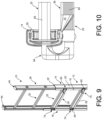
- the fly section 26 may be nested in at least two ways. In one way, the fly web 36 is adjacent and alongside the base web 20 when the right fly flange 34 and left fly flange 38 extend outward from the fly web 36 away from the center line 50 of the extension ladder 10, as shown in figures 11 and 12 . In another way, the fly web 36 is spaced apart from the base web 20 when the right fly flange 34 and left fly flange 38 extend inward from the fly web 36 toward the center line 50 of the extension ladder 10, as shown in figures 9 and 10 .
- the ladder 10 comprises a cap 44, as shown in figure 17A and 17B , attached to the top 40 with no object attached to the cap 44 above the cap 44.
- the cap 44 having a surface 46 which extends between the right fly flange 34 and the fly web 36 and the left fly flange 38.
- the ladder 10 comprises a locking mechanism 48 to fix and lock the fly section 26 to the base section 12 at a desired position relative to the base section 12.
- the extension ladder 10 can support at least 136.08 kg (300 lbs) and has a duty rating of at least 1A.
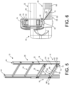
- the right base rail 14 may have a right stem 52 extending inwards from the right base flange 18 toward the left base flange 22, and has a left stem 54 extending inwards from the left base flange 22 toward the right base flange 18, as shown in figures 6 , 8 , 10 , 12 and 20 .
- the right and left stems 52, 54 position the right fly rail 28 in between the right and left rail base flanges a desired distance and act as guides for the right fly rail 28 as the right fly rail 28 moves relative to the right base rail 14, and to position the right fly rail 34 away from rivet upsets.
- the stems additionally serve to strengthen the right base rail 14 and add buttressing and stiffness to the right base rail 14.
- the stems extend along the length of the right base rail 14.
- the stems may have stems, same as the right base rail 14 for the same purpose and function.
- the stems may be between 2.54 and 5.08 mm (.1 and .2 inches) long and about 2.54 mm (.1 inches) wide.
- a first base rung 58 of the base rungs 24 has a first flattened end 60 that conforms with and fits against and contacts and is in parallel with the right base flange 18 of the right base rail 14, as shown in figures 5 , 7 , 9 and 11 .
- the base section 12 may have at least a first fastener 62, such as a rivet, which extends through the first flattened end 60 and the right base flange 18 to fasten the first flattened end 60 to the right base flange 18.
- the first base rung 58 may have a second flattened end 64 that is fastened to the left base rail 16 with a second fastener 66.
- the first base rung 58 may have a step portion 68 which is flat and extends between the first and second flattened ends 60, 64.
- the flat step portion 68 may be essentially perpendicularly oriented to the first and second flattened ends 60, 64.
- the first base rung 58 may have a first tapered portion 70 which has a slope 72 that extends inwards between the step portion 68 and the first flattened end 60, and may have a second tapered portion 74 which has a slope 72 that extends inwards between the step portion 68 and the second flattened end 64.
- the flattened ends and their tapered portions are formed by crimping, with the tapered portions having a slope 72 of between 20 degrees and 65 degrees and preferably about 45 degrees.
- the tapered portion begins about 1.5 inches to about 3 inches from the inner edge of the right base flange 18, and the same for the left side of the rung.
- the fly rungs 32 may be swaged to the fly webs 36 of the first and second fly rails and form a swage joint 69, as shown in figure 4A .
- the rungs may be hollow and have a step portion 68 which has grooves or serrations to provide for traction when a user places a foot on the stepping surface 46 of a fly rung.
- the cap 44 may have an attachment portion 76 that is disposed between and extends along the fly web 36 and the right fly flange 34 and the left fly flange 38, and a ceiling portion 78 attached to and extending from and above the attachment portion 76, as shown in figures 17A and 17B .
- the ceiling portion 78 having a solid surface 46 and a perimeter that defines a ridge that extends along and on the top 40 of the right fly rail 28 in contact and on the fly web 36 and the right fly flange 34 and the left fly flange 38.
- the ceiling portion 78 may extend upward in an arc shape.
- the ceiling portion 78 may have ribs 80 disposed on the solid surface 46.
- each base rail upon which the extension ladder 10 rests on ground when the extension ladder 10 is leaning against an object either is the bare rail itself or has a foot 82 on the bottom 42.
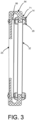
- the locking mechanism 48 is a J-lock 84 that extends from a side of a J-lock rung 25 of the base section 12 and back through a lock hole 71 in the right base rail 14 and into a rung 32 of the fly section 26 through an end of the rung, which is hollow, to lock the fly section 26 and the base section 12 together, as shown in figure 3 .
- the fly section 26 and the base section 12 are configured to be in a locked position so their rungs are alongside each other, so the portions of the fly section 26 and base section 12 which overlap have their steps in line so the foot of a user fits on and steps on the rung of the base section 12 and with the aligned adjacent rung of the fly section 26.
- the fly section 26 is configured to slide relative to the base section 12 when the J-lock 84 is pulled out from the rung of the fly section 26.
- the J-lock rung 25 from which the J-lock 84 extends has a squared or flat face 86 instead of a crimped end.
- the J-lock 84 fits in and extends from the flat face 86, as shown in figures 3 , 13 and 15 .
- the locking mechanism 48 may be a swing lock 88 that is attached to the right fly flange 34 and the left fly flange 38 of the right base rail 14 and which encompasses a rung of the base section 12 and an adjoining rung of the fly section 26 at a desired position of the fly section 26 relative to the base section 12, as shown in figures 14 and 16 .
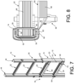
- the right fly rail 28 may have a wall 90 attached to the right fly flange 34 and the left fly flange 38 and extending between the right fly flange 34 and the left fly flange 38 and in parallel and spaced relation to the fly web 36, as shown in figures 5-8 .
- the fly web 36 and the wall 90 and the right and left fly flanges 34, 38 forming a cross sectional shape of a rectangle with the wall 90 closing the C cross-section. This is another way the fly section 26 may be nested within the base section 12, where the right fly rail 28 is nested in the right base rail 14.
- Figures 5 and 6 show this embodiment with J-locks 84, where the fly rungs 32 have a hollow rectangular cross-section which corresponds to the cross-section of the J lock that fits into the fly rung.
- Figures 7 and 8 show this embodiment with swing locks 88, where the fly rungs 32 have a D-shaped cross-section, with the step portion 68 of the fly rung having a slight angle downwards to better receive a foot of a user when the user places a foot on the fly rung.
- Figure 13 shows a C-shaped cross-section of a base rail over a rectangular or box shaped cross-section of a fly rail with J-locks 84.
- Figure 14 shows a C-shaped cross-section of a base rail over a rectangular or box cross-section of a fly rail with swing locks 88.
- Figure 15 shows a C-shaped cross-section of a base rail over a C-shaped cross-section of a fly rail with J-locks 84.
- Figure 16 shows a C-shaped cross-section of a base rail over a C-shaped cross-section of a fly rail with swing locks 88.
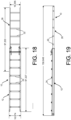
- Figure 18 is an overhead view of the extension ladder 10 at maximum extension.
- Figure 19 is a side view of the extension ladder 10 at maximum extension.
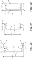
- Figure 20 shows a typical base rail profile.
- Figure 21 shows a typical profile of C-shaped fly rail.
- Figure 22 shows a typical profile of a rectangular shaped fly rail.
- Conventional extension ladders have the rail sections stacked on top of each other.
- the height of the extension ladders stacked on top of each other is defined as a stack height.
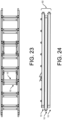
- the smaller stack height 92 of extension ladders 10 stacked on top of each other, as shown in figures 23 and 24 permits a higher product density in palletization and containerization which will reduce shipping cost.
- a first extension ladder having a second extension ladder placed on top of the first extension ladder or alongside the first extension ladder has a stack height 92 1/3 less than the stack height of a first conventional extension ladder having a second conventional extension ladder placed on top of the first conventional extension ladder or alongside the first extension ladder, where the conventional extension ladder has the fly section 26 alongside the base section 12 but not nested in the base section 12.
- the stack height would be the height of at least the width of four rails, the width of the base and fly rails of a first conventional extension ladder plus the width of the base and fly rails of the second conventional ladder on top of the first conventional ladder.
- the stack height is about the width of the base rail 14 of the first extension ladder 10 plus the width of the base rail 14 of the second extension ladder 10 on top of the first extension ladder 10.
Landscapes
- Engineering & Computer Science (AREA)
- Mechanical Engineering (AREA)
- Ladders (AREA)
- Programmable Controllers (AREA)
Claims (9)
- Ausziehleiter (10) umfassend:einen Basisabschnitt (12) mit einer rechten Basisschiene (14) und einer linken Basisschiene (16), die parallel und beabstandet zu der rechten Basisschiene (14) angeordnet ist, wobei die rechte Basisschiene (14) einen C-förmigen Querschnitt aufweist, der durch einen an einem Basissteg (20) befestigten rechten Basisflansch (18) und einen an dem Basissteg (20) befestigten linken Basisflansch (22) gebildet ist, wobei der Basissteg (20) zwischen dem rechten Basisflansch (18) und dem linken Basisflansch (22) angeordnet ist, wobei der Basisabschnitt (12) Basissprossen (24) aufweist, die an der rechten und linken Basisschiene befestigt und vor und außerhalb des rechten Basisflansches (18) der rechten Basisschiene (14) angeordnet sind;einen Auszugsabschnitt (26) mit einem rechten Auszugsholm (28) und einem linken Auszugsholm (30), die parallel und beabstandet zu dem rechten Auszugsholm (28) angeordnet sind, wobei der Auszugsabschnitt (26) Auszugssprossen (32) aufweist, die an dem rechten und linken Auszugsholm (30) befestigt sind und sich zwischen diesen erstrecken, wobei der rechte Basisflansch (18) und der linke Basisflansch (22) um den rechten Auszugsholm (28) herum angeordnet sind, wobei der rechte Auszugsholm (28) zwischen dem rechten und linken Basisflansch angeordnet ist, der Auszugsabschnitt (26) in den Basisabschnitt (12) eingesetzt ist und dazu konfiguriert ist, mindestens einen Teil des Auszugsabschnitts (26) über den Basisabschnitt (12) nach oben zu schieben und den Auszugsabschnitt (26) relativ zu dem Basisabschnitt (12) wieder nach unten zu schieben, während er mit dem Basisabschnitt (12) über die rechte und linke Basisschiene, die um den rechten bzw. linken Auszugsholm (30) angeordnet sind, in Eingriff bleibt, der rechte Auszugsholm (28) durch einen rechten Auszugsflansch (34), der an einem Auszugssteg (36) befestigt ist, und einen linken Auszugsflansch (38), der an dem Auszugssteg (36) befestigt ist, gebildet ist, wobei der Auszugssteg (36) zwischen dem rechten Auszugsflansch (34) und dem linken Auszugsflansch (38) angeordnet ist, wobei der rechte Auszugsholm (28) eine Oberseite und eine Unterseite (42) aufweist, wobei die Oberseite Teil des Bereichs ist, der dazu konfiguriert ist, über dem Basisabschnitt (12) nach oben zu gleiten;eine oben angebrachte Kappe (44), wobei die Kappe (44) eine Fläche aufweist, die sich zwischen dem rechten Auszugsflansch (34) und dem Auszugssteg (36) sowie dem linken Auszugsflansch (38) erstreckt; undeinen Verriegelungsmechanismus (48), um den Auszugsabschnitt (26) an dem Basisabschnitt (12) in einer gewünschten Position relativ zu dem Basisabschnitt (12) zu fixieren und zu verriegeln,wobei die Basisholme (14, 16) und die Auszugsholme (28, 30) gerade sind,dadurch gekennzeichnet, dass der Verriegelungsmechanismus (48) eine J-Verriegelung (84) ist, das sich von einer Seite einer Sprosse des Basisabschnitts (12) und zurück durch ein Verriegelungsloch (71) im rechten Basisholm (14) und in eine Sprosse des Auszugsabschnitts (26) erstreckt, um den Auszugsabschnitt (26) und den Basisabschnitt (12) miteinander zu verriegeln, wobei der Auszugsabschnitt (26) dazu konfiguriert ist, relativ zu dem Basisabschnitt (12) zu gleiten, wenn die J-Verriegelung (84) aus der Sprosse des Auszugsabschnitts (26) herausgezogen wird;dass die Basissprossen (24) einen sich verjüngenden Abschnitt an jedem Ende aufweisen, der ein abgeflachtes Ende aufweist, das gegen den jeweiligen Basisflansch passt und diesen in Kontakt bringt und parallel zu diesem ist; und dass der Basisholm eine J-Verriegelungssprosse (25) mit einer quadratischen oder flachen Fläche (86) aufweist, von der sich die J-Verriegelung (84) erstreckt.
- Leiter nach Anspruch 1, wobei der rechte Basisholm (14) einen rechten Schaft (52) aufweist, der sich von dem rechten Basisflansch (18) nach innen in Richtung des linken Basisflansches (22) erstreckt, und einen linken Schaft (54) aufweist, der sich von dem linken Basisflansch (22) nach innen in Richtung des rechten Basisflansches (18) erstreckt, wobei der rechte und der linke Schaft den rechten Auszugsholm (28) in einem gewünschten Abstand zwischen dem rechten und dem linken Basisholm positionieren und als Führungen für den rechten Auszugsholm (28) dienen, wenn sich der rechte Auszugsholm (28) relativ zum rechten Basisholm (14) bewegt, und um den rechten Auszugsholm (28) von Nietstauchungen entfernt zu positionieren.
- Leiter nach Anspruch 1 oder 2, wobei eine erste Basissprosse (58) der Basissprossen ein erstes abgeflachtes Ende (60) aufweist, das mit dem rechten Basisflansch (18) des rechten Basisholms (14) übereinstimmt und an diesem anliegt, in Kontakt bringt und parallel zu diesem ist, wobei sich mindestens ein erstes Befestigungselement (62) durch das erste abgeflachte Ende (60) und den rechten Basisflansch (18) erstreckt, um das erste abgeflachte Ende (60) am rechten Basisflansch (18) zu befestigen, wobei die erste Basissprosse (58) ein zweites abgeflachtes Ende aufweist, das an dem linken Basisholm (16) mit einem zweiten Befestigungselement befestigt ist, wobei die erste Basissprosse (58) einen Stufenabschnitt aufweist, der flach ist und sich zwischen dem ersten und dem zweiten abgeflachten Ende erstreckt, wobei der flache Stufenabschnitt im Wesentlichen senkrecht zu dem ersten und dem zweiten abgeflachten Ende ausgerichtet ist.
- Leiter nach Anspruch 3, wobei die erste Basissprosse (58) einen ersten verjüngten Abschnitt (70) aufweist, der eine Neigung aufweist, die sich zwischen dem Stufenabschnitt und dem ersten abgeflachten Ende (60) nach innen erstreckt, und einen zweiten verjüngten Abschnitt (74) aufweist, der eine Neigung (72) aufweist, die sich zwischen dem Stufenabschnitt und dem zweiten abgeflachten Ende nach innen erstreckt.
- Leiter nach einem der vorhergehenden Ansprüche, wobei die Kappe (44) einen Befestigungsabschnitt (76) aufweist, der zwischen dem Auszugssteg (36) und dem rechten Auszugsflansch (34) und dem linken Auszugsflansch (38) angeordnet ist und sich entlang dieser erstreckt, und einen Deckenabschnitt (78), der an dem Befestigungsabschnitt (76) befestigt ist und sich von diesem aus und über diesem erstreckt, wobei der Deckenabschnitt (78) eine feste Oberfläche und einen Umfang aufweist, der einen Grat definiert, der sich entlang und auf der Oberseite des rechten Auszugsholms (28) in Kontakt mit und auf dem Auszugssteg (36) und dem rechten Auszugsflansch (34) und dem linken Auszugsflansch (38) erstreckt.
- Leiter nach Anspruch 5, wobei sich der Deckenabschnitt (78) bogenförmig nach oben erstreckt.
- Leiter nach Anspruch 5 oder 6, wobei der Deckenabschnitt (78) Rippen (80) aufweist, die auf der festen Oberfläche angeordnet sind.
- Leiter nach einem der vorhergehenden Ansprüche, wobei der rechte Auszugsholm (28) eine Wand aufweist, die an dem rechten Auszugsflansch (34) und dem linken Auszugsflansch (38) befestigt ist und sich zwischen dem rechten Auszugsflansch (34) und dem linken Auszugsflansch (38) und parallel und beabstandet zu dem Auszugssteg (36) erstreckt, wobei der Auszugssteg (36) und die Wand sowie der rechte und der linke Auszugsflansch im Querschnitt die Form eines Rechtecks bilden.
- Leiter nach einem der vorhergehenden Ansprüche, wobei die Leiter eine zweite Ausziehleiter (10) beinhaltet, die einen Auszugsabschnitt (26) aufweist, der in einem Basisabschnitt (12) verschachtelt ist, wobei die zweite Ausziehleiter (10) auf der Ausziehleiter (10) gestapelt ist und eine Stapelhöhe aufweist, die mindestens 1/3 geringer ist als eine Stapelhöhe einer ersten Ausziehleiter (10), die einen Auszugsabschnitt (26) oberhalb eines Basisabschnitts (12) aufweist, der auf einer zweiten Ausziehleiter (10) gestapelt ist, die einen Auszugsabschnitt (26) oberhalb eines Basisabschnitts (12) aufweist.
Priority Applications (1)
| Application Number | Priority Date | Filing Date | Title |
|---|---|---|---|
| EP23206812.2A EP4293190A1 (de) | 2018-08-02 | 2019-07-30 | Ausziehleiter, system und verfahren |
Applications Claiming Priority (1)
| Application Number | Priority Date | Filing Date | Title |
|---|---|---|---|
| US16/053,407 US20200040656A1 (en) | 2018-08-02 | 2018-08-02 | Extension Ladder, System and Method |
Related Child Applications (1)
| Application Number | Title | Priority Date | Filing Date |
|---|---|---|---|
| EP23206812.2A Division EP4293190A1 (de) | 2018-08-02 | 2019-07-30 | Ausziehleiter, system und verfahren |
Publications (2)
| Publication Number | Publication Date |
|---|---|
| EP3604730A1 EP3604730A1 (de) | 2020-02-05 |
| EP3604730B1 true EP3604730B1 (de) | 2023-11-01 |
Family
ID=67513429
Family Applications (2)
| Application Number | Title | Priority Date | Filing Date |
|---|---|---|---|
| EP19189209.0A Active EP3604730B1 (de) | 2018-08-02 | 2019-07-30 | Ausziehleiter, system und verfahren |
| EP23206812.2A Withdrawn EP4293190A1 (de) | 2018-08-02 | 2019-07-30 | Ausziehleiter, system und verfahren |
Family Applications After (1)
| Application Number | Title | Priority Date | Filing Date |
|---|---|---|---|
| EP23206812.2A Withdrawn EP4293190A1 (de) | 2018-08-02 | 2019-07-30 | Ausziehleiter, system und verfahren |
Country Status (6)
| Country | Link |
|---|---|
| US (1) | US20200040656A1 (de) |
| EP (2) | EP3604730B1 (de) |
| CN (1) | CN110792388A (de) |
| AU (3) | AU2019205968A1 (de) |
| CA (1) | CA3050659C (de) |
| MX (1) | MX2019009025A (de) |
Families Citing this family (9)
| Publication number | Priority date | Publication date | Assignee | Title |
|---|---|---|---|---|
| CN205713939U (zh) * | 2016-05-03 | 2016-11-23 | 厦门新技术集成有限公司 | 一种伸缩梯子的伸缩腿 |
| CN113187375A (zh) | 2016-10-05 | 2021-07-30 | 伟英企业有限公司 | 梯子、用于梯子的机构和部件以及相关方法 |
| US10151144B2 (en) | 2016-12-14 | 2018-12-11 | Werner Co. | Ladder, wide rung and method |
| US10538966B2 (en) | 2017-05-10 | 2020-01-21 | Werner Co. | Ceiling ladder, deep step and method |
| US11034420B2 (en) * | 2019-02-13 | 2021-06-15 | Ross Hoffmann | Rescue ladder attachment |
| US20200370372A1 (en) * | 2019-02-13 | 2020-11-26 | Ross Hoffmann | Rescue ladder attachment |
| US20200256125A1 (en) * | 2019-02-13 | 2020-08-13 | Ross Hoffmann | Rescue ladder attachment |
| CA3126531C (en) * | 2020-07-30 | 2023-12-12 | Werner Co. | Climbing product having an extendable section lock assembly, and methods for using and producing a climbing product |
| CN112576996B (zh) * | 2021-02-24 | 2021-05-25 | 赣通通信股份有限公司 | 用于市政监测的智慧灯杆 |
Family Cites Families (14)
| Publication number | Priority date | Publication date | Assignee | Title |
|---|---|---|---|---|
| JPS5022Y1 (de) * | 1969-02-22 | 1975-01-06 | ||
| DE2001416C3 (de) * | 1970-01-14 | 1979-02-08 | Walter 7120 Bissingen Kuemmerlin | Leiter |
| US4182431A (en) * | 1978-03-13 | 1980-01-08 | Little Giant Industries Inc. | Combination extension and step ladder rungs therefor |
| JPS593112Y2 (ja) * | 1980-01-28 | 1984-01-27 | 井上鉄工株式会社 | 伸縮梯子 |
| DE3446255A1 (de) * | 1984-12-19 | 1986-06-19 | Nikolaus Adalbert 7730 Villingen-Schwenningen Kümmerlin | Leiter |
| KR940020881U (ko) * | 1993-02-01 | 1994-09-17 | 유회관 | 사다리의 높낮이 조절장치 |
| US5738186A (en) * | 1994-03-01 | 1998-04-14 | Foxdale Developments Limited | Extensible ladder |
| US5758745A (en) * | 1996-07-18 | 1998-06-02 | Werner Co. | Extension ladder, combination end cap/guide bracket, and method for climbing |
| FR2813918B1 (fr) * | 2000-09-14 | 2003-03-28 | Centaure | Echelle transformable a plusieurs plans |
| CN2782905Y (zh) * | 2005-03-24 | 2006-05-24 | 苏州市金安通讯设备有限公司 | 轻便绝缘梯 |
| JP6262601B2 (ja) * | 2014-05-30 | 2018-01-17 | 紀美代 中尾 | 三連伸縮梯子 |
| CN205713939U (zh) * | 2016-05-03 | 2016-11-23 | 厦门新技术集成有限公司 | 一种伸缩梯子的伸缩腿 |
| US11486199B2 (en) * | 2016-12-28 | 2022-11-01 | Werner Co. | Ladder, end cap and method |
| US11851949B2 (en) * | 2018-01-30 | 2023-12-26 | Werner Co. | Multipurpose ladder and method |
-
2018
- 2018-08-02 US US16/053,407 patent/US20200040656A1/en not_active Abandoned
-
2019
- 2019-07-15 AU AU2019205968A patent/AU2019205968A1/en not_active Abandoned
- 2019-07-26 CA CA3050659A patent/CA3050659C/en active Active
- 2019-07-30 CN CN201910695399.2A patent/CN110792388A/zh active Pending
- 2019-07-30 EP EP19189209.0A patent/EP3604730B1/de active Active
- 2019-07-30 MX MX2019009025A patent/MX2019009025A/es unknown
- 2019-07-30 EP EP23206812.2A patent/EP4293190A1/de not_active Withdrawn
-
2021
- 2021-04-23 AU AU2021202533A patent/AU2021202533C1/en not_active Ceased
-
2023
- 2023-07-06 AU AU2023204349A patent/AU2023204349A1/en not_active Abandoned
Also Published As
| Publication number | Publication date |
|---|---|
| EP4293190A1 (de) | 2023-12-20 |
| US20200040656A1 (en) | 2020-02-06 |
| NZ755426A (en) | 2020-12-18 |
| AU2021202533A1 (en) | 2021-05-27 |
| AU2023204349A1 (en) | 2023-07-27 |
| AU2021202533C1 (en) | 2023-10-26 |
| CA3050659C (en) | 2022-09-13 |
| EP3604730A1 (de) | 2020-02-05 |
| MX2019009025A (es) | 2020-02-03 |
| AU2021202533B2 (en) | 2023-04-06 |
| CA3050659A1 (en) | 2020-02-02 |
| CN110792388A (zh) | 2020-02-14 |
| AU2019205968A1 (en) | 2020-02-20 |
Similar Documents
| Publication | Publication Date | Title |
|---|---|---|
| EP3604730B1 (de) | Ausziehleiter, system und verfahren | |
| US8973707B2 (en) | Toe board for scaffolding and a method for producing a toe board | |
| US4870798A (en) | Double lock standing seam roof sheet | |
| US7093401B2 (en) | Light gauge metal truss system and method | |
| US10087633B2 (en) | End lap system for roof cladding sheets | |
| US5758745A (en) | Extension ladder, combination end cap/guide bracket, and method for climbing | |
| US12492596B2 (en) | Three section extension ladder | |
| CA2406542C (en) | Swimming pool ladder | |
| US6929094B1 (en) | Restraint system, apparatus and method for ladder system | |
| US20180112411A1 (en) | Subframe support for retrofit roof | |
| US5241785A (en) | Standing seam panel and construction method therefor | |
| US11866995B2 (en) | Ladder with box rails having a collar | |
| EP0736647A1 (de) | Gerüstboden | |
| JP6341715B2 (ja) | 折板葺きの屋根構造 | |
| NZ755426B2 (en) | Extension Ladder, System and Method | |
| US6354228B1 (en) | Pallet formed from interlocking members | |
| US4936067A (en) | Stud extender interlock and method of erection | |
| WO1988002426A1 (en) | Suspension unit | |
| WO2018137001A1 (en) | Metal sheeting clip | |
| US20230279666A1 (en) | Brackets for Attachment of Posts to Joists | |
| AU2017101373C4 (en) | Spacer | |
| JP3192455U (ja) | 道路防音壁の吸音板 | |
| KR20240001683U (ko) | 방호선반용 체결부재 및 이를 포함하는 방호선반 | |
| KR20210022430A (ko) | 블라인드의 헤드레일용 브라켓 | |
| NZ736762B (en) | Spacer |
Legal Events
| Date | Code | Title | Description |
|---|---|---|---|
| PUAI | Public reference made under article 153(3) epc to a published international application that has entered the european phase |
Free format text: ORIGINAL CODE: 0009012 |
|
| STAA | Information on the status of an ep patent application or granted ep patent |
Free format text: STATUS: THE APPLICATION HAS BEEN PUBLISHED |
|
| AK | Designated contracting states |
Kind code of ref document: A1 Designated state(s): AL AT BE BG CH CY CZ DE DK EE ES FI FR GB GR HR HU IE IS IT LI LT LU LV MC MK MT NL NO PL PT RO RS SE SI SK SM TR |
|
| AX | Request for extension of the european patent |
Extension state: BA ME |
|
| STAA | Information on the status of an ep patent application or granted ep patent |
Free format text: STATUS: REQUEST FOR EXAMINATION WAS MADE |
|
| STAA | Information on the status of an ep patent application or granted ep patent |
Free format text: STATUS: EXAMINATION IS IN PROGRESS |
|
| 17P | Request for examination filed |
Effective date: 20200805 |
|
| RBV | Designated contracting states (corrected) |
Designated state(s): AL AT BE BG CH CY CZ DE DK EE ES FI FR GB GR HR HU IE IS IT LI LT LU LV MC MK MT NL NO PL PT RO RS SE SI SK SM TR |
|
| 17Q | First examination report despatched |
Effective date: 20200824 |
|
| GRAP | Despatch of communication of intention to grant a patent |
Free format text: ORIGINAL CODE: EPIDOSNIGR1 |
|
| STAA | Information on the status of an ep patent application or granted ep patent |
Free format text: STATUS: GRANT OF PATENT IS INTENDED |
|
| INTG | Intention to grant announced |
Effective date: 20230130 |
|
| GRAJ | Information related to disapproval of communication of intention to grant by the applicant or resumption of examination proceedings by the epo deleted |
Free format text: ORIGINAL CODE: EPIDOSDIGR1 |
|
| STAA | Information on the status of an ep patent application or granted ep patent |
Free format text: STATUS: EXAMINATION IS IN PROGRESS |
|
| GRAP | Despatch of communication of intention to grant a patent |
Free format text: ORIGINAL CODE: EPIDOSNIGR1 |
|
| STAA | Information on the status of an ep patent application or granted ep patent |
Free format text: STATUS: GRANT OF PATENT IS INTENDED |
|
| INTG | Intention to grant announced |
Effective date: 20230522 |
|
| GRAS | Grant fee paid |
Free format text: ORIGINAL CODE: EPIDOSNIGR3 |
|
| GRAA | (expected) grant |
Free format text: ORIGINAL CODE: 0009210 |
|
| STAA | Information on the status of an ep patent application or granted ep patent |
Free format text: STATUS: THE PATENT HAS BEEN GRANTED |
|
| AK | Designated contracting states |
Kind code of ref document: B1 Designated state(s): AL AT BE BG CH CY CZ DE DK EE ES FI FR GB GR HR HU IE IS IT LI LT LU LV MC MK MT NL NO PL PT RO RS SE SI SK SM TR |
|
| REG | Reference to a national code |
Ref country code: GB Ref legal event code: FG4D |
|
| REG | Reference to a national code |
Ref country code: CH Ref legal event code: EP |
|
| REG | Reference to a national code |
Ref country code: DE Ref legal event code: R096 Ref document number: 602019040434 Country of ref document: DE |
|
| REG | Reference to a national code |
Ref country code: IE Ref legal event code: FG4D |
|
| REG | Reference to a national code |
Ref country code: LT Ref legal event code: MG9D |
|
| REG | Reference to a national code |
Ref country code: NL Ref legal event code: MP Effective date: 20231101 |
|
| PG25 | Lapsed in a contracting state [announced via postgrant information from national office to epo] |
Ref country code: GR Free format text: LAPSE BECAUSE OF FAILURE TO SUBMIT A TRANSLATION OF THE DESCRIPTION OR TO PAY THE FEE WITHIN THE PRESCRIBED TIME-LIMIT Effective date: 20240202 |
|
| PG25 | Lapsed in a contracting state [announced via postgrant information from national office to epo] |
Ref country code: IS Free format text: LAPSE BECAUSE OF FAILURE TO SUBMIT A TRANSLATION OF THE DESCRIPTION OR TO PAY THE FEE WITHIN THE PRESCRIBED TIME-LIMIT Effective date: 20240301 |
|
| PG25 | Lapsed in a contracting state [announced via postgrant information from national office to epo] |
Ref country code: LT Free format text: LAPSE BECAUSE OF FAILURE TO SUBMIT A TRANSLATION OF THE DESCRIPTION OR TO PAY THE FEE WITHIN THE PRESCRIBED TIME-LIMIT Effective date: 20231101 |
|
| REG | Reference to a national code |
Ref country code: AT Ref legal event code: MK05 Ref document number: 1627418 Country of ref document: AT Kind code of ref document: T Effective date: 20231101 |
|
| PG25 | Lapsed in a contracting state [announced via postgrant information from national office to epo] |
Ref country code: NL Free format text: LAPSE BECAUSE OF FAILURE TO SUBMIT A TRANSLATION OF THE DESCRIPTION OR TO PAY THE FEE WITHIN THE PRESCRIBED TIME-LIMIT Effective date: 20231101 |
|
| PG25 | Lapsed in a contracting state [announced via postgrant information from national office to epo] |
Ref country code: AT Free format text: LAPSE BECAUSE OF FAILURE TO SUBMIT A TRANSLATION OF THE DESCRIPTION OR TO PAY THE FEE WITHIN THE PRESCRIBED TIME-LIMIT Effective date: 20231101 |
|
| PG25 | Lapsed in a contracting state [announced via postgrant information from national office to epo] |
Ref country code: ES Free format text: LAPSE BECAUSE OF FAILURE TO SUBMIT A TRANSLATION OF THE DESCRIPTION OR TO PAY THE FEE WITHIN THE PRESCRIBED TIME-LIMIT Effective date: 20231101 |
|
| PG25 | Lapsed in a contracting state [announced via postgrant information from national office to epo] |
Ref country code: NL Free format text: LAPSE BECAUSE OF FAILURE TO SUBMIT A TRANSLATION OF THE DESCRIPTION OR TO PAY THE FEE WITHIN THE PRESCRIBED TIME-LIMIT Effective date: 20231101 Ref country code: LT Free format text: LAPSE BECAUSE OF FAILURE TO SUBMIT A TRANSLATION OF THE DESCRIPTION OR TO PAY THE FEE WITHIN THE PRESCRIBED TIME-LIMIT Effective date: 20231101 Ref country code: IS Free format text: LAPSE BECAUSE OF FAILURE TO SUBMIT A TRANSLATION OF THE DESCRIPTION OR TO PAY THE FEE WITHIN THE PRESCRIBED TIME-LIMIT Effective date: 20240301 Ref country code: GR Free format text: LAPSE BECAUSE OF FAILURE TO SUBMIT A TRANSLATION OF THE DESCRIPTION OR TO PAY THE FEE WITHIN THE PRESCRIBED TIME-LIMIT Effective date: 20240202 Ref country code: ES Free format text: LAPSE BECAUSE OF FAILURE TO SUBMIT A TRANSLATION OF THE DESCRIPTION OR TO PAY THE FEE WITHIN THE PRESCRIBED TIME-LIMIT Effective date: 20231101 Ref country code: BG Free format text: LAPSE BECAUSE OF FAILURE TO SUBMIT A TRANSLATION OF THE DESCRIPTION OR TO PAY THE FEE WITHIN THE PRESCRIBED TIME-LIMIT Effective date: 20240201 Ref country code: AT Free format text: LAPSE BECAUSE OF FAILURE TO SUBMIT A TRANSLATION OF THE DESCRIPTION OR TO PAY THE FEE WITHIN THE PRESCRIBED TIME-LIMIT Effective date: 20231101 Ref country code: PT Free format text: LAPSE BECAUSE OF FAILURE TO SUBMIT A TRANSLATION OF THE DESCRIPTION OR TO PAY THE FEE WITHIN THE PRESCRIBED TIME-LIMIT Effective date: 20240301 |
|
| PG25 | Lapsed in a contracting state [announced via postgrant information from national office to epo] |
Ref country code: SE Free format text: LAPSE BECAUSE OF FAILURE TO SUBMIT A TRANSLATION OF THE DESCRIPTION OR TO PAY THE FEE WITHIN THE PRESCRIBED TIME-LIMIT Effective date: 20231101 Ref country code: RS Free format text: LAPSE BECAUSE OF FAILURE TO SUBMIT A TRANSLATION OF THE DESCRIPTION OR TO PAY THE FEE WITHIN THE PRESCRIBED TIME-LIMIT Effective date: 20231101 Ref country code: PL Free format text: LAPSE BECAUSE OF FAILURE TO SUBMIT A TRANSLATION OF THE DESCRIPTION OR TO PAY THE FEE WITHIN THE PRESCRIBED TIME-LIMIT Effective date: 20231101 Ref country code: NO Free format text: LAPSE BECAUSE OF FAILURE TO SUBMIT A TRANSLATION OF THE DESCRIPTION OR TO PAY THE FEE WITHIN THE PRESCRIBED TIME-LIMIT Effective date: 20240201 Ref country code: LV Free format text: LAPSE BECAUSE OF FAILURE TO SUBMIT A TRANSLATION OF THE DESCRIPTION OR TO PAY THE FEE WITHIN THE PRESCRIBED TIME-LIMIT Effective date: 20231101 Ref country code: HR Free format text: LAPSE BECAUSE OF FAILURE TO SUBMIT A TRANSLATION OF THE DESCRIPTION OR TO PAY THE FEE WITHIN THE PRESCRIBED TIME-LIMIT Effective date: 20231101 |
|
| PG25 | Lapsed in a contracting state [announced via postgrant information from national office to epo] |
Ref country code: DK Free format text: LAPSE BECAUSE OF FAILURE TO SUBMIT A TRANSLATION OF THE DESCRIPTION OR TO PAY THE FEE WITHIN THE PRESCRIBED TIME-LIMIT Effective date: 20231101 |
|
| PG25 | Lapsed in a contracting state [announced via postgrant information from national office to epo] |
Ref country code: CZ Free format text: LAPSE BECAUSE OF FAILURE TO SUBMIT A TRANSLATION OF THE DESCRIPTION OR TO PAY THE FEE WITHIN THE PRESCRIBED TIME-LIMIT Effective date: 20231101 |
|
| PG25 | Lapsed in a contracting state [announced via postgrant information from national office to epo] |
Ref country code: SK Free format text: LAPSE BECAUSE OF FAILURE TO SUBMIT A TRANSLATION OF THE DESCRIPTION OR TO PAY THE FEE WITHIN THE PRESCRIBED TIME-LIMIT Effective date: 20231101 |
|
| PG25 | Lapsed in a contracting state [announced via postgrant information from national office to epo] |
Ref country code: SM Free format text: LAPSE BECAUSE OF FAILURE TO SUBMIT A TRANSLATION OF THE DESCRIPTION OR TO PAY THE FEE WITHIN THE PRESCRIBED TIME-LIMIT Effective date: 20231101 Ref country code: SK Free format text: LAPSE BECAUSE OF FAILURE TO SUBMIT A TRANSLATION OF THE DESCRIPTION OR TO PAY THE FEE WITHIN THE PRESCRIBED TIME-LIMIT Effective date: 20231101 Ref country code: IT Free format text: LAPSE BECAUSE OF FAILURE TO SUBMIT A TRANSLATION OF THE DESCRIPTION OR TO PAY THE FEE WITHIN THE PRESCRIBED TIME-LIMIT Effective date: 20231101 Ref country code: EE Free format text: LAPSE BECAUSE OF FAILURE TO SUBMIT A TRANSLATION OF THE DESCRIPTION OR TO PAY THE FEE WITHIN THE PRESCRIBED TIME-LIMIT Effective date: 20231101 Ref country code: DK Free format text: LAPSE BECAUSE OF FAILURE TO SUBMIT A TRANSLATION OF THE DESCRIPTION OR TO PAY THE FEE WITHIN THE PRESCRIBED TIME-LIMIT Effective date: 20231101 Ref country code: CZ Free format text: LAPSE BECAUSE OF FAILURE TO SUBMIT A TRANSLATION OF THE DESCRIPTION OR TO PAY THE FEE WITHIN THE PRESCRIBED TIME-LIMIT Effective date: 20231101 |
|
| REG | Reference to a national code |
Ref country code: DE Ref legal event code: R097 Ref document number: 602019040434 Country of ref document: DE |
|
| PLBE | No opposition filed within time limit |
Free format text: ORIGINAL CODE: 0009261 |
|
| STAA | Information on the status of an ep patent application or granted ep patent |
Free format text: STATUS: NO OPPOSITION FILED WITHIN TIME LIMIT |
|
| 26N | No opposition filed |
Effective date: 20240802 |
|
| PG25 | Lapsed in a contracting state [announced via postgrant information from national office to epo] |
Ref country code: SI Free format text: LAPSE BECAUSE OF FAILURE TO SUBMIT A TRANSLATION OF THE DESCRIPTION OR TO PAY THE FEE WITHIN THE PRESCRIBED TIME-LIMIT Effective date: 20231101 |
|
| PG25 | Lapsed in a contracting state [announced via postgrant information from national office to epo] |
Ref country code: SI Free format text: LAPSE BECAUSE OF FAILURE TO SUBMIT A TRANSLATION OF THE DESCRIPTION OR TO PAY THE FEE WITHIN THE PRESCRIBED TIME-LIMIT Effective date: 20231101 |
|
| REG | Reference to a national code |
Ref country code: DE Ref legal event code: R119 Ref document number: 602019040434 Country of ref document: DE |
|
| PG25 | Lapsed in a contracting state [announced via postgrant information from national office to epo] |
Ref country code: MC Free format text: LAPSE BECAUSE OF FAILURE TO SUBMIT A TRANSLATION OF THE DESCRIPTION OR TO PAY THE FEE WITHIN THE PRESCRIBED TIME-LIMIT Effective date: 20231101 |
|
| REG | Reference to a national code |
Ref country code: CH Ref legal event code: PL |
|
| PG25 | Lapsed in a contracting state [announced via postgrant information from national office to epo] |
Ref country code: LU Free format text: LAPSE BECAUSE OF NON-PAYMENT OF DUE FEES Effective date: 20240730 |
|
| GBPC | Gb: european patent ceased through non-payment of renewal fee |
Effective date: 20240730 |
|
| PG25 | Lapsed in a contracting state [announced via postgrant information from national office to epo] |
Ref country code: LU Free format text: LAPSE BECAUSE OF NON-PAYMENT OF DUE FEES Effective date: 20240730 |
|
| PG25 | Lapsed in a contracting state [announced via postgrant information from national office to epo] |
Ref country code: DE Free format text: LAPSE BECAUSE OF NON-PAYMENT OF DUE FEES Effective date: 20250201 |
|
| PG25 | Lapsed in a contracting state [announced via postgrant information from national office to epo] |
Ref country code: CH Free format text: LAPSE BECAUSE OF NON-PAYMENT OF DUE FEES Effective date: 20240731 Ref country code: BE Free format text: LAPSE BECAUSE OF NON-PAYMENT OF DUE FEES Effective date: 20240731 |
|
| PG25 | Lapsed in a contracting state [announced via postgrant information from national office to epo] |
Ref country code: FR Free format text: LAPSE BECAUSE OF NON-PAYMENT OF DUE FEES Effective date: 20240731 |
|
| PG25 | Lapsed in a contracting state [announced via postgrant information from national office to epo] |
Ref country code: GB Free format text: LAPSE BECAUSE OF NON-PAYMENT OF DUE FEES Effective date: 20240730 |
|
| REG | Reference to a national code |
Ref country code: BE Ref legal event code: MM Effective date: 20240731 |
|
| PG25 | Lapsed in a contracting state [announced via postgrant information from national office to epo] |
Ref country code: IE Free format text: LAPSE BECAUSE OF NON-PAYMENT OF DUE FEES Effective date: 20240730 |
|
| PG25 | Lapsed in a contracting state [announced via postgrant information from national office to epo] |
Ref country code: FI Free format text: LAPSE BECAUSE OF FAILURE TO SUBMIT A TRANSLATION OF THE DESCRIPTION OR TO PAY THE FEE WITHIN THE PRESCRIBED TIME-LIMIT Effective date: 20231101 |
|
| PG25 | Lapsed in a contracting state [announced via postgrant information from national office to epo] |
Ref country code: RO Free format text: LAPSE BECAUSE OF FAILURE TO SUBMIT A TRANSLATION OF THE DESCRIPTION OR TO PAY THE FEE WITHIN THE PRESCRIBED TIME-LIMIT Effective date: 20231101 |
|
| PG25 | Lapsed in a contracting state [announced via postgrant information from national office to epo] |
Ref country code: CY Free format text: LAPSE BECAUSE OF FAILURE TO SUBMIT A TRANSLATION OF THE DESCRIPTION OR TO PAY THE FEE WITHIN THE PRESCRIBED TIME-LIMIT; INVALID AB INITIO Effective date: 20190730 |
|
| PG25 | Lapsed in a contracting state [announced via postgrant information from national office to epo] |
Ref country code: HU Free format text: LAPSE BECAUSE OF FAILURE TO SUBMIT A TRANSLATION OF THE DESCRIPTION OR TO PAY THE FEE WITHIN THE PRESCRIBED TIME-LIMIT; INVALID AB INITIO Effective date: 20190730 |