EP3604148A1 - Trocknungsvorrichtung und verpackungsmaschine - Google Patents
Trocknungsvorrichtung und verpackungsmaschine Download PDFInfo
- Publication number
- EP3604148A1 EP3604148A1 EP19178032.9A EP19178032A EP3604148A1 EP 3604148 A1 EP3604148 A1 EP 3604148A1 EP 19178032 A EP19178032 A EP 19178032A EP 3604148 A1 EP3604148 A1 EP 3604148A1
- Authority
- EP
- European Patent Office
- Prior art keywords
- air
- drying device
- blowers
- generates
- packaging machine
- Prior art date
- Legal status (The legal status is an assumption and is not a legal conclusion. Google has not performed a legal analysis and makes no representation as to the accuracy of the status listed.)
- Granted
Links
Images
Classifications
-
- B—PERFORMING OPERATIONS; TRANSPORTING
- B65—CONVEYING; PACKING; STORING; HANDLING THIN OR FILAMENTARY MATERIAL
- B65B—MACHINES, APPARATUS OR DEVICES FOR, OR METHODS OF, PACKAGING ARTICLES OR MATERIALS; UNPACKING
- B65B61/00—Auxiliary devices, not otherwise provided for, for operating on sheets, blanks, webs, binding material, containers or packages
- B65B61/002—Auxiliary devices, not otherwise provided for, for operating on sheets, blanks, webs, binding material, containers or packages for drying glued or sealed packages
-
- F—MECHANICAL ENGINEERING; LIGHTING; HEATING; WEAPONS; BLASTING
- F26—DRYING
- F26B—DRYING SOLID MATERIALS OR OBJECTS BY REMOVING LIQUID THEREFROM
- F26B15/00—Machines or apparatus for drying objects with progressive movement; Machines or apparatus with progressive movement for drying batches of material in compact form
- F26B15/10—Machines or apparatus for drying objects with progressive movement; Machines or apparatus with progressive movement for drying batches of material in compact form with movement in a path composed of one or more straight lines, e.g. compound, the movement being in alternate horizontal and vertical directions
- F26B15/12—Machines or apparatus for drying objects with progressive movement; Machines or apparatus with progressive movement for drying batches of material in compact form with movement in a path composed of one or more straight lines, e.g. compound, the movement being in alternate horizontal and vertical directions the lines being all horizontal or slightly inclined
- F26B15/18—Machines or apparatus for drying objects with progressive movement; Machines or apparatus with progressive movement for drying batches of material in compact form with movement in a path composed of one or more straight lines, e.g. compound, the movement being in alternate horizontal and vertical directions the lines being all horizontal or slightly inclined the objects or batches of materials being carried by endless belts
-
- F—MECHANICAL ENGINEERING; LIGHTING; HEATING; WEAPONS; BLASTING
- F26—DRYING
- F26B—DRYING SOLID MATERIALS OR OBJECTS BY REMOVING LIQUID THEREFROM
- F26B21/00—Arrangements for supplying or controlling air or other gases for drying solid materials or objects
- F26B21/50—Ducting arrangements from the source of air or other gases to the materials or objects being dried
-
- B—PERFORMING OPERATIONS; TRANSPORTING
- B65—CONVEYING; PACKING; STORING; HANDLING THIN OR FILAMENTARY MATERIAL
- B65B—MACHINES, APPARATUS OR DEVICES FOR, OR METHODS OF, PACKAGING ARTICLES OR MATERIALS; UNPACKING
- B65B53/00—Shrinking wrappers, containers, or container covers during or after packaging
- B65B53/02—Shrinking wrappers, containers, or container covers during or after packaging by heat
- B65B53/04—Shrinking wrappers, containers, or container covers during or after packaging by heat supplied by liquids
Definitions
- the invention relates to a drying device for drying packaging according to the preamble of claim 1.
- drying devices are usually used together with packaging machines.
- water residues can remain on the packaging for various reasons, for example after shrinking packaging by spraying with water or in a water bath. Drying devices are used to remove such water residues as completely as possible.
- drying devices for drying packaging is from the EP 2 368 800 A1 known.
- drying devices often achieve their drying effect by blowing an air stream over the packaging to be dried.
- Large side channel blowers are often used for this purpose in connection with lines and branches to the actual nozzles.
- this increases the complexity of the blower itself, since the lines and branches have to be designed and manufactured for the application purpose, and on the other hand also increases the complexity of the entire drying device, since space has to be provided for the laying of the lines.
- a sealing device which shrinks a film surrounding a product by hot air.
- the hot air is blown sideways in the direction of the products by several fans. Only the side sections of the packaged products are blown. Upper and lower sections are protected from the hot air flow by conveyor belts.
- An object of the invention is to provide a drying device, the construction and manufacture of which is simplified by simple improvements in terms of design. This object is achieved according to the invention by a drying device with the features of claim 1 and by a packaging machine with the features of claim 9. Advantageous further developments are specified in the respective dependent claims.
- a drying device for drying packages which is set up to remove water from a surface of the packages by a first air stream, which is in a first, downward direction.
- the drying device is characterized in that the first air flow is generated by a blower arrangement which comprises two blowers and an air guiding element arranged between them.
- Wrapping articles which generally do not exceed a volume of 5000 cm 3 can be regarded as packaging in the sense of this application.
- a direction that is essentially perpendicular to a footprint of the drying device or an associated packaging machine can be regarded as a downward direction.
- a direction essentially parallel to the direction of gravity can also be viewed as a downward direction.
- the construction of the blower arrangement can be made very simple and, moreover, line elements can be saved.
- the construction according to the invention enables fans to be used whose total energy consumption is lower than that of the side channel blowers used in conventional drying devices.
- the air guiding element has two air inlets. It is particularly favorable if a blower is arranged at each air inlet of the air guiding element. A particularly advantageous distribution of the first air stream can be achieved by suitably arranging the air inlets.
- the blower is a turbomachine, preferably a turbocompressor. This enables particularly high energy savings to be achieved.
- the air guide element has an air outlet that has a rectangular cross section. This allows the first air stream to be given a particularly suitable shape.
- blowers generates a second air flow and the other of the blowers generates a third air flow, the second and third air flows running in opposite directions. This can ensure a particularly homogeneous pressure distribution within the air guiding element and thus a particularly uniform first air flow.
- one of the blowers generates a second air flow and the other of the blowers generates a third air flow, the first air flow being transverse, preferably perpendicular, to the second and third air flows.
- This arrangement has proven to be advantageous because it allows the first air flow to be directed unimpeded onto the packages to be dried without being adversely affected by the blowers, for example.
- two blower arrangements can be provided, each with two blowers and one air guiding element arranged between them.
- both fan arrangements can be configured in the same way. It is conceivable that the two blower arrangements are arranged one behind the other in a conveying direction of the packaging. A direction in which the packages are conveyed through the drying device can be regarded as the conveying direction.
- the invention also relates to a packaging machine with a forming station, a sealing station and a cutting station, which are arranged in this order along a production direction and are designed to produce filled packages from a first and a second film, the packaging machine further comprising a downstream of the Cutting stations arranged shrinking station configured to shrink the packages by immersion in a preheated or hot water bath or by spraying with preheated or hot water and comprising a drying device of the type described above.
- a direction in which the packaging is conveyed by the packaging machine can be regarded as the direction of production. In the drying device in particular, it can match the conveying direction.
- Such a packaging machine represents a particularly advantageous application of the drying device explained above, since the packaging must be wetted with water from all sides for shrinking and accordingly there is a high risk that water residues remain on the surface of the packaging.
- the air guiding element extends transversely to the production direction. In this way it is possible in a particularly simple manner that the first air stream extends over the entire width of a production area running in the direction of production.
- one of the blowers can generate a second air flow which runs in a second direction, which is oriented transversely, preferably perpendicularly, to the production direction and / or to the first direction.
- This arrangement has proven to be advantageous because it allows the first air stream to be directed unimpeded onto the packages to be dried without being adversely affected by the blower, for example.
- blowers may also be advantageous if another one of the blowers generates a third air flow that runs in a third direction that is oriented opposite to the second direction. This can ensure a particularly homogeneous pressure distribution within the air guiding element and thus a particularly uniform first air flow.
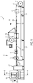
- Fig. 1 shows a schematic view of a packaging machine 1 according to the invention, exemplarily designed as a thermoforming packaging machine.
- This packaging machine 1 can comprise a forming station 2, a sealing station 3 and a cutting station 6. These can be arranged in this order in a working direction R on a machine frame 6.
- the cutting station 6 can have a transverse cutting device 4 and a longitudinal cutting device 5.
- a feed roller 7 can be located on the machine frame 9, from which a lower film 8 can be pulled off.
- the lower film 8 can be transported into the forming station 2 by a feed device, not shown. There, open packages 14 can be formed as troughs in the bottom film 8 by deep drawing. Several packs 14 lying next to one another can be formed. The open packages 14 can be transported together with the surrounding area of the lower film 8 to an insertion section 15, where they can be filled with product 16.
- the filled packs 14 can then be transported together with the region of the lower film 8 surrounding them to the sealing station 3. There they can be sealed with an upper film 10. Sealing the top film 10 onto the open packages 14 results in closed packages 14 ′, which can be separated at the cutting station 6 and then transported away by a discharge device 13.
- the sealing device 3 can be configured to evacuate and / or gas a package 14 to be closed before the sealing. This can be particularly advantageous in the packaging of food products, since their shelf life can be increased when packaging under vacuum or, if necessary, with a protective gas.
- the preferably shrinkable lower film 8 can be applied to the product 16 to be packaged.
- the packagings 14 ′ formed in this way can have a sealing edge and the sections 16 of the shrunk lower film 8 and the upper film 10 which closely surround the product to be packaged. Furthermore, there can be a section between the film sections lying against the product 16 and the sealing edge in which the lower film 8 and the upper film 10 lie closely against one another without being welded to one another.
- the packaging devices 14 'formed in this way can be cut out and placed on the discharge device 13 by the subsequently arranged cutting devices 4, 5.
- the packaging machine has on the output side a shrinking station 17 which is only shown schematically.
- This can be designed in such a way that it heats the packaging 14 'supplied to it from all sides, so that the lower film 8 and the upper film 10 can be shrunk so that the section between the film sections adjacent to the product 16 and the sealing edge is shrunk is reduced or disappears entirely.
- the lower film 8 and the upper film 10 can lie completely against the goods to be packaged. This enables an optically appealing product presentation to be achieved.
- the shrinking station 17 can be designed such that it briefly brings the packaging 14 'into contact with water at a temperature below the boiling point, for example by immersing it in a water bath or by spraying.
- the heated water can cause an intensive and rapid shrinkage without the product being adversely affected by the heat.
- the packaging machine 1 can further comprise a drying device 18. This can be arranged downstream of the shrinking station 17.
- the drying device 18 may include a fan assembly 19 that may be configured to generate a first airflow 20.
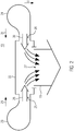
- the fan assembly 19 is in Figure 1 only shown schematically. A more detailed sectional view from the perspective indicated by the line II-II is in Figure 2 shown.
- the first air stream 20 can run in a first, downward direction U.
- the first direction U runs perpendicularly to an installation surface 21 of the packaging machine 1.
- the blower arrangement 19 can accordingly comprise an air guiding element 22. This can extend transversely, preferably perpendicularly, to the first direction U.
- the air guiding element 22 can be arranged between a first blower 23 and a second blower 24. Furthermore, the air guiding element 22, as in FIG Figure 2 shown, have a first air inlet 25 and a second air inlet 26.
- the first fan 23 can be arranged on the first air inlet 25 of the air guiding element 22.
- the second blower 24 can be arranged on the second air inlet 26 of the air guiding element 22.
- the blowers 23, 24 are preferably arranged directly on the air inlets 25, 26, that is to say there are no further lines and in particular no branches are provided between the blowers 23, 24 and the air inlets 25, 26.
- the air guiding element 22 can have an air outlet 27. The first air stream 19 can flow through this.
- the first blower 23 can be configured to generate a second air flow 28. This can extend in a second direction 29, which can be oriented transversely, preferably perpendicularly, to the first direction U.
- the second fan 24 may be configured to generate a third airflow 30. This can run in a third direction 31, which can also be oriented transversely, preferably perpendicularly, to the first direction U.
- the third direction 31 can be oriented opposite to the second direction 29.
- the second and third directions 29, 31 can also each run transversely, preferably perpendicular, to the production direction R, which is perpendicular to the plane of the drawing of Figure 2 runs.
Landscapes
- Engineering & Computer Science (AREA)
- Mechanical Engineering (AREA)
- General Engineering & Computer Science (AREA)
- Drying Of Solid Materials (AREA)
- Auxiliary Devices For And Details Of Packaging Control (AREA)
Abstract
Description
- Die Erfindung bezieht sich auf eine Trocknungsvorrichtung zum Trocknen von Verpackungen gemäß dem Oberbegriff von Anspruch 1.
- Solche Trocknungsvorrichtungen werden in der Regel zusammen mit Verpackungsmaschinen eingesetzt. Beim Verpacken von Produkten durch Verpackungsmaschinen können auf den erzeugten Verpackungen aus verschiedenen Gründen Wasserrückstände verbleiben, zum Beispiel nach dem Schrumpfen von Verpackungen durch Besprühen mit Wasser oder in einem Wasserbad. Um solche Wasserrückstände möglichst restlos zu entfernen, werden Trocknungsvorrichtungen eingesetzt.
- Ein Beispiel für Trocknungsvorrichtungen zum Trocknen von Verpackungen ist aus der
EP 2 368 800 A1 bekannt. Wie daran zu erkennen, erreichen Trocknungsvorrichtungen ihre Trocknungswirkung häufig dadurch, dass ein Luftstrom über die zu trocknenden Verpackungen geblasen wird. Dazu werden häufig große Seitenkanalverdichter in Verbindung mit Leitungen und Verzweigungen zu den eigentlichen Düsen eingesetzt. Dies erhöht einerseits die Komplexität des Gebläses an sich, da die Leitungen und Verzweigungen für den Anwendungszweck ausgelegt und gefertigt werden müssen, zum Anderen auch die Komplexität der gesamten Trocknungsvorrichtung, da Platz für die Verlegung der Leitungen vorgesehen sein muss. - Aus der
US 3 785 276 A ist eine Versiegelungsvorrichtung bekannt, die eine ein Produkt umgebende Folie durch Heißluft schrumpft. Die Heißluft wird durch mehrere Gebläse seitlich in Richtung der Produkte geblasen. Dabei werden nur die seitlichen Abschnitte der verpackten Produkte angeblasen. Obere und untere Abschnitte werden durch Förderbänder vor dem Heißluftstrom geschützt. - Eine Aufgabe der Erfindung ist es, eine Trocknungsvorrichtung anzugeben, deren Konstruktion und Fertigung durch konstruktiv möglichst einfache Verbesserungen vereinfacht ist. Diese Aufgabe wird erfindungsgemäß gelöst durch eine Trocknungsvorrichtung mit den Merkmalen des Anspruchs 1 sowie durch eine Verpackungsmaschine mit den Merkmalen des Anspruchs 9. Vorteilhafte Weiterbildungen sind in den jeweiligen abhängigen Ansprüchen angegeben.
- Es wird eine Trocknungsvorrichtung zum Trocknen von Verpackungen vorgesehen, die dazu eingerichtet ist, Wasser von einer Oberfläche der Verpackungen durch einen ersten Luftstrom, der in einer ersten, nach unten orientierten Richtung verläuft, zu entfernen. Die Trocknungsvorrichtung zeichnet sich dadurch aus, dass der erste Luftstrom durch eine Gebläseanordnung erzeugt wird, die zwei Gebläse und ein dazwischen angeordnetes Luftleitelement umfasst.
- Als Verpackungen im Sinne dieser Anmeldung können umhüllende Gegenstände angesehen werden, die in der Regel ein Volumen von 5000 cm3 nicht überschreiten. Als eine nach unten orientierte Richtung kann eine Richtung angesehen werden, die im Wesentlichen senkrecht auf eine Aufstellfläche der Trocknungsvorrichtung oder einer zugehörigen Verpackungsmaschine zu verläuft. Eine im Wesentlichen parallel zur Richtung der Schwerkraft verlaufende Richtung kann ebenso als nach unten orientierte Richtung angesehen werden.
- Durch das Vorsehen von zwei Gebläsen und einem dazwischen angeordneten Luftleitelement kann die Konstruktion der Gebläseanordnung sehr einfach ausgeführt sein und außerdem Leitungselemente eingespart werden. Darüber hinaus hat sich überraschenderweise herausgestellt, dass durch die erfindungsgemäße Konstruktion Gebläse verwendet werden können, deren summierter Energieverbrauch geringer ist als derjenige der in konventionellen Trocknungsvorrichtungen verwendeten Seitenkanalverdichter.
- Es ist vorteilhaft, wenn das Luftleitelement zwei Lufteinlässe aufweist. Besonders günstig ist es, wenn an jedem Lufteinlass des Luftleitelements ein Gebläse angeordnet ist. Durch geeignete Anordnung der Lufteinlässe kann eine besonders vorteilhafte Verteilung des ersten Luftstroms erreicht werden.
- In einer vorteilhaften Variante ist das Gebläse eine Strömungsmaschine, vorzugsweise ein Turboverdichter. Hierdurch kann eine besonders hohe Energieeinsparung erzielt werden.
- Es ist denkbar, dass das Luftleitelement einen Luftauslass aufweist, der einen rechteckigen Querschnitt hat. Dadurch kann dem ersten Luftstrom eine besonders geeignete Form gegeben werden.
- Es ist zweckmäßig, wenn eines der Gebläse einen zweiten Luftstrom erzeugt und das andere der Gebläse einen dritten Luftstrom erzeugt, wobei der zweite und der dritte Luftstrom in entgegengesetzten Richtungen verlaufen. Dies kann eine besonders homogene Druckverteilung innerhalb des Luftleitelements und damit einen besonders gleichmäßigen ersten Luftstrom gewährleisten.
- Es kann vorteilhaft sein, wenn eines der Gebläse einen zweiten Luftstrom erzeugt und das andere der Gebläse einen dritten Luftstrom erzeugt, wobei der erste Luftstrom quer, vorzugsweise senkrecht, zu dem zweiten und dem dritten Luftstrom verläuft. Diese Anordnung hat sich als vorteilhaft herausgestellt, weil dadurch der erste Luftstrom ungehindert auf die zu trocknenden Verpackungen gerichtet werden kann, ohne beispielsweise durch die Gebläse beeinträchtigt zu werden.
- In einer weiteren vorteilhaften Variante der Trocknungsvorrichtung können zwei Gebläseanordnungen mit jeweils zwei Gebläsen und jeweils einem dazwischen angeordneten Luftleitelement vorgesehen sein. Insbesondere können beide Gebläseanordnungen gelichartig konfiguriert sein. Es ist denkbar, dass die beiden Gebläseanordnungen in einer Förderrichtung der Verpackungen hintereinander angeordnet sind. Als Förderrichtung kann eine Richtung angesehen werden, in der die Verpackungen durch die Trocknungsvorrichtung hindurch gefördert werden.
- Die Erfindung bezieht sich auch auf eine Verpackungsmaschine mit einer Formstation, einer Siegelstation und einer Schneidstationen, welche in dieser Reihenfolge entlang einer Produktionsrichtung angeordnet und dazu eingerichtet sind, befüllte Verpackungen aus einer ersten und einer zweiten Folie herzustellen, wobei die Verpackungsmaschine des Weiteren eine stromabwärts der Schneidstationen angeordnete Schrumpfstation, die dazu konfiguriert ist, die Verpackungen durch Eintauchen in ein vorgewärmtes oder heißes Wasserbad oder durch Besprühen mit vorgewärmtem oder heißem Wasser zu schrumpfen, und eine Trocknungsvorrichtung der vorstehend beschriebenen Art umfasst. Als Produktionsrichtung kann eine Richtung angesehen werden, in der die Verpackungen durch die Verpackungsmaschine gefördert werden. Sie kann insbesondere in der Trocknungsvorrichtung mit der Förderrichtung übereinstimmen.
- Eine solche Verpackungsmaschine stellt eine besonders vorteilhafte Anwendung der oben erläuterten Trocknungsvorrichtung dar, da die Verpackungen zum Schrumpfen von allen Seiten mit Wasser benetzt werden müssen und dementsprechend eine hohe Gefahr besteht, dass Wasserrückstände auf der Oberfläche der Verpackungen verbleiben.
- Es kann vorteilhaft sein, wenn das Luftleitelement sich quer zu der Produktionsrichtung erstreckt. Auf diese Weise ist es besonders einfach möglich, dass der erste Luftstrom sich über die gesamte Breite einer in Produktionsrichtung verlaufenden Produktionsfläche erstreckt.
- In einer weiteren Variante kann eines der Gebläse einen zweiten Luftstrom erzeugen, der in einer zweiten Richtung verläuft, die quer, vorzugsweise senkrecht, zu der Produktionsrichtung und/oder zu der ersten Richtung orientiert ist. Diese Anordnung hat sich als vorteilhaft herausgestellt, weil dadurch der erste Luftstrom ungehindert auf die zu trocknenden Verpackungen gerichtet werden kann, ohne beispielsweise durch das Gebläse beeinträchtigt zu werden.
- Es kann außerdem vorteilhaft sein, wenn ein anderes der Gebläse einen dritten Luftstrom erzeugt, der in einer dritten Richtung verläuft, die der zweiten Richtung entgegengesetzt orientiert ist. Dies kann eine besonders homogene Druckverteilung innerhalb des Luftleitelements und damit einen besonders gleichmäßigen ersten Luftstrom gewährleisten.
- Die Erfindung bezieht sich auf eine Trocknungsvorrichtung sowie eine Verpackungsmaschine der vorstehend beschriebenen Art. Im Folgenden wird ein vorteilhaftes Ausführungsbeispiel anhand von Zeichnungen näher erläutert.
- Figur 1
- zeigt eine schematische Seitenansicht einer Verpackungsmaschine in einer Ausführungsform als Tiefziehverpackungsmaschine mit einer erfindungsgemäßen Trocknungsvorrichtung.
- Figur 2
- zeigt eine schematische Schnittansicht einer Gebläseanordnung in der in
Figur 1 durch die Linie II-II angedeuteten Perspektive. -
Fig. 1 zeigt in schematischer Ansicht eine erfindungsgemäße Verpackungsmaschine 1, beispielhaft als Tiefziehverpackungsmaschine ausgeführt. Diese Verpackungsmaschine 1 kann eine Formstation 2, eine Siegelstation 3 sowie eine Schneidstation 6 umfassen. Diese können in dieser Reihenfolge in einer Arbeitsrichtung R an einem Maschinengestell 6 angeordnet sein. Die Schneidstation 6 kann eine Querschneideeinrichtung 4 und eine Längsschneideeinrichtung 5 aufweisen. Eingangsseitig kann sich an dem Maschinengestell 9 eine Zufuhrrolle 7 befinden, von der eine Unterfolie 8 abgezogen werden kann. - Die Unterfolie 8 kann durch eine nicht gezeigte Vorschubeinrichtung in die Formstation 2 transportiert werden. Dort können durch Tiefziehen offene Verpackungen 14 als Mulden in die Unterfolie 8 geformt werden. Es können dabei mehrere nebeneinander liegende Verpackungen 14 gebildet werden. Die offenen Verpackungen 14 können zusammen mit dem umgebenden Bereich der Unterfolie 8 zu einer Einlegestrecke 15 weitertransportiert werden, wo sie mit Produkt 16 befüllt werden können.
- Anschließend kann ein Transport der befüllten Verpackungen 14 zusammen mit dem sie umgebenden Bereich der Unterfolie 8 zu der Siegelstation 3 erfolgen. Dort können sie mit einer Oberfolie 10 versiegelt werden. Durch das Ansiegeln der Oberfolie 10 auf die offenen Verpackungen 14 entstehen verschlossene Verpackungen 14', die an der Schneidstation 6 vereinzelt und danach durch eine Abführeinrichtung 13 abtransportiert werden können.
- Die Siegelvorrichtung 3 kann dazu konfiguriert sein, eine zu verschließende Verpackung 14 vor dem Siegeln zu evakuieren und/oder zu begasen. Dies kann insbesondere bei der Verpackung von Lebensmittelprodukten vorteilhaft sein, da deren Haltbarkeit beim Verpacken unter Vakuum oder ggf. mit einem Schutzgaserhöht werden kann. Beim Evakuieren, ggf. Begasen und Versiegeln kann ein Anlegen der vorzugsweise schrumpffähigen Unterfolie 8 an das zu verpackende Produkt 16 erfolgen. Die so gebildeten Verpackungen 14' können einen Siegelrand und das zu verpackende Produkt 16 eng anliegend umgebende Abschnitte von geschrumpfter Unterfolie 8 und Oberfolie 10 aufweisen. Ferner kann sich zwischen den am Produkt 16 anliegenden Folienabschnitten und dem Siegelrand ein Abschnitt befinden, in dem Unterfolie 8 und Oberfolie 10 eng aneinander anliegen, ohne miteinander verschweißt zu sein.
- Durch die nachfolgend angeordneten Schneideinrichtungen 4, 5 können die so gebildeten Verpackungen 14' ausgeschnitten und auf der Abführeinrichtung 13 abgesetzt werden.
- In dem gezeigten Ausführungsbeispiel weist die Verpackungsmaschine ausgangsseitig eine nur schematisch dargestellte Schrumpfstation 17 auf. Diese kann so ausgebildet sein, dass sie die ihr zugeführte Verpackung 14' von allen Seiten her erwärmt, so dass ein Nachschrumpfen der Unterfolie 8 und der Oberfolie 10 so erfolgen kann, dass der Abschnitt zwischen den am Produkt 16 anliegenden Folienabschnitten und dem Siegelrand durch Schrumpfen verringert wird oder ganz verschwindet. Als Ergebnis können die Unterfolie 8 und die Oberfolie 10 vollständig an dem zu verpackenden Gut anliegen. Dadurch kann eine optisch ansprechende Produktpräsentation erreicht werden.
- Die Schrumpfstation 17 kann so ausgebildet sein, dass sie die Verpackung 14' mit Wasser auf einer Temperatur unterhalb des Siedepunktes kurzzeitig in Kontakt bringt, beispielsweise durch Eintauchen in ein Wasserbad oder durch Besprühen. Durch das erwärmte Wasser kann eine intensive und schnelle Schrumpfung erfolgen, ohne dass das Produkt durch die Wärme nachteilig beeinflußt wird.
- Die Verpackungsmaschine 1 kann des Weiteren eine Trocknungsvorrichtung 18 umfassen. Diese kann stromabwärts der Schrumpfstation 17 angeordnet sein. Die Trocknungsvorrichtung 18 kann eine Gebläseanordnung 19 enthalten, die zum Erzeugen eines ersten Luftstroms 20 konfiguriert sein kann. Die Gebläseanordnung 19 ist in
Figur 1 lediglich schematisch dargestellt. Eine detailliertere Schnittansicht aus der durch die Linie II-II angedeuteten Perspektive ist inFigur 2 dargestellt. Wie inFigur 1 zu erkennen ist, kann der erste Luftstrom 20 in einer ersten, nach unten orientierten Richtung U verlaufen. Im vorliegenden Ausführungsbeispiel verläuft die erste Richtung U senkrecht auf eine Aufstellfläche 21 der Verpackungsmaschine 1 zu. - In der Schnittdarstellung der Gebläseanordnung 19 in
Figur 2 sind Komponenten der Gebläseanordnung 19 zu erkennen. Die Gebläseanordnung 19 kann demnach ein Luftleitelement 22 umfassen. Dieses kann sich quer, vorzugsweise senkrecht, zu der ersten Richtung U erstrecken. Das Luftleitelement 22 kann zwischen einem ersten Gebläse 23 und einem zweiten Gebläse 24 angeordnet sein. Des Weiteren kann das Luftleitelement 22, wie inFigur 2 dargestellt, einen ersten Lufteinlass 25 und einen zweiten Lufteinlass 26 aufweisen. - Das erste Gebläse 23 kann an dem ersten Lufteinlass 25 des Luftleitelements 22 angeordnet sein. Das zweite Gebläse 24 kann an dem zweiten Lufteinlass 26 des Luftleitelements 22 angeordnet sein. Vorzugsweise sind die Gebläse 23, 24 direkt an den Lufteinlässen 25, 26 angeordnet, das heißt es sind keine weiteren Leitungen und insbesondere keine Verzweigungen zwischen den Gebläsen 23, 24 und den Lufteinlässe 25, 26 vorgesehen. Außerdem kann das Luftleitelement 22 einen Luftauslass 27 aufweisen. Durch diesen kann der erste Luftstrom 19 ausströmen.
- Das erste Gebläse 23 kann dazu eingerichtet sein, einen zweiten Luftstrom 28 zu erzeugen. Dieser kann sich in einer zweiten Richtung 29 erstrecken, die quer, vorzugsweise senkrecht, zu der ersten Richtung U orientiert sein kann. Das zweite Gebläse 24 kann zum Erzeugen eines dritten Luftstroms 30 konfiguriert sein. Dieser kann in einer dritten Richtung 31 verlaufen, die ebenfalls quer, vorzugsweise senkrecht, zu der ersten Richtung U orientiert sein kann. Dabei kann die dritte Richtung 31 entgegengesetzt der zweiten Richtung 29 orientiert sein. Die zweite und dritte Richtung 29, 31 können außerdem jeweils quer, vorzugsweise senkrecht, zu der Produktionsrichtung R verlaufen, die senkrecht zu der Zeichnungsebene von
Figur 2 verläuft.
Claims (12)
- Trocknungsvorrichtung (18) zum Trocknen von Verpackungen (), die dazu eingerichtet ist, Wasser von einer Oberfläche der Verpackungen (14') durch einen ersten Luftstrom (20), der in einer ersten, nach unten orientierten Richtung (U) verläuft, zu entfernen, dadurch gekennzeichnet, dass der erste Luftstrom (20) durch eine Gebläseanordnung (19) erzeugt wird, die zwei Gebläse (23, 24) und ein dazwischen angeordnetes Luftleitelement (22) umfasst.
- Trocknungsvorrichtung nach Anspruch 1, dadurch gekennzeichnet, dass das Luftleitelement (22) zwei Lufteinlässe (25, 26) aufweist.
- Trocknungsvorrichtung nach einem der vorangehenden Ansprüche, dadurch gekennzeichnet, dass an jedem Lufteinlass (25, 26) des Luftleitelements (22) ein Gebläse (23, 24) angeordnet ist.
- Trocknungsvorrichtung nach einem der vorangehenden Ansprüche, dadurch gekennzeichnet, dass das Gebläse (23, 24) eine Strömungsmaschine, vorzugsweise ein Turboverdichter, ist.
- Trocknungsvorrichtung nach einem der vorangehenden Ansprüche, dadurch gekennzeichnet, dass das Luftleitelement (22) einen Luftauslass (27) aufweist, der einen im Wesentlichen rechteckigen Querschnitt hat.
- Trocknungsvorrichtung nach einem der vorangehenden Ansprüche, dadurch gekennzeichnet, dass eines der Gebläse (23, 24) einen zweiten Luftstrom (28) erzeugt und das andere der Gebläse (23, 24) einen dritten Luftstrom (30) erzeugt, wobei der zweite und der dritte Luftstrom in entgegengesetzten Richtungen (29, 31) verlaufen.
- Trocknungsvorrichtung nach einem der vorangehenden Ansprüche, dadurch gekennzeichnet, dass eines der Gebläse (23, 24) einen zweiten Luftstrom (28) erzeugt und das andere der Gebläse (23, 24) einen dritten Luftstrom (30) erzeugt, wobei der erste Luftstrom (20) quer, vorzugsweise senkrecht, zu dem zweiten und dem dritten Luftstrom (28, 30) verläuft.
- Trocknungsvorrichtung nach einem der vorangehenden Ansprüche, dadurch gekennzeichnet, dass zwei Gebläseanordnungen (19) mit jeweils zwei Gebläsen (23, 24) und jeweils einem dazwischen angeordneten Luftleitelement (22) vorgesehen sind.
- Verpackungsmaschine (1) mit einer Formstation (2), einer Siegelstation (3) und einer Schneidstation (6), welche in dieser Reihenfolge entlang einer Produktionsrichtung (R) angeordnet und dazu eingerichtet sind, befüllte Verpackungen (14, 14') aus einer ersten und einer zweiten Folie (8, 10) herzustellen, wobei die Verpackungsmaschine (1) des Weiteren eine stromabwärts der Schneidstation (6) angeordnete Schrumpfstation (17), die dazu konfiguriert ist, die Verpackungen (14') durch Eintauchen in ein Wasserbad oder durch Besprühen mit Wasser zu schrumpfen, und eine Trocknungsvorrichtung (18) gemäß einem der vorangehenden Ansprüche umfasst.
- Verpackungsmaschine nach Anspruch 9, dadurch gekennzeichnet, dass das Luftleitelement (22) sich quer zu der Produktionsrichtung (R) erstreckt.
- Verpackungsmaschine nach Anspruch 9 oder 10, dadurch gekennzeichnet, dass eines der Gebläse (23, 24) einen zweiten Luftstrom (28) erzeugt, der in einer zweiten Richtung (29) verläuft, die quer, vorzugsweise senkrecht, zu der Produktionsrichtung (R) und/oder zu der ersten Richtung (U) orientiert ist.
- Verpackungsmaschine nach Anspruch 11, dadurch gekennzeichnet, dass ein anderes der Gebläse (23, 24) einen dritten Luftstrom (30) erzeugt, der in einer dritten Richtung (31) verläuft, die der zweiten Richtung (29) entgegengesetzt orientiert ist.
Applications Claiming Priority (1)
| Application Number | Priority Date | Filing Date | Title |
|---|---|---|---|
| DE102018212646.1A DE102018212646A1 (de) | 2018-07-30 | 2018-07-30 | Trocknungsvorrichtung und Verpackungsmaschine |
Publications (2)
| Publication Number | Publication Date |
|---|---|
| EP3604148A1 true EP3604148A1 (de) | 2020-02-05 |
| EP3604148B1 EP3604148B1 (de) | 2021-08-25 |
Family
ID=66751958
Family Applications (1)
| Application Number | Title | Priority Date | Filing Date |
|---|---|---|---|
| EP19178032.9A Active EP3604148B1 (de) | 2018-07-30 | 2019-06-04 | Trocknungsvorrichtung und verpackungsmaschine |
Country Status (4)
| Country | Link |
|---|---|
| EP (1) | EP3604148B1 (de) |
| CN (1) | CN210823097U (de) |
| DE (1) | DE102018212646A1 (de) |
| ES (1) | ES2896050T3 (de) |
Cited By (1)
| Publication number | Priority date | Publication date | Assignee | Title |
|---|---|---|---|---|
| US12275570B2 (en) | 2021-02-26 | 2025-04-15 | Acm Chemistries, Inc. | Separator beads for manufactured concrete products |
Citations (6)
| Publication number | Priority date | Publication date | Assignee | Title |
|---|---|---|---|---|
| GB831666A (en) * | 1957-07-22 | 1960-03-30 | Diamond National Corp | Improvements in or relating to dryers |
| DE2021948A1 (de) * | 1970-05-05 | 1972-02-03 | Danfoss As | Verfahren und Vorrichtung zum Trocknen von Motorkompressoren |
| US3785276A (en) | 1969-02-06 | 1974-01-15 | Norr Eng Mfg Corp | Equipment for conditioning and packaging a product |
| GB2119341A (en) * | 1982-04-24 | 1983-11-16 | Kraemer & Grebe Kg | Method of and apparatus for producing a package |
| WO2004000650A1 (de) * | 2002-06-20 | 2003-12-31 | Multivac Sepp Haggenmüller Gmbh & Co. Kg | Verfahren und vorrichtung zum verpacken |
| EP2368800A1 (de) | 2010-03-24 | 2011-09-28 | MULTIVAC Sepp Haggenmüller GmbH & Co KG | Einrichtung zum Transportieren von Objekten |
Family Cites Families (4)
| Publication number | Priority date | Publication date | Assignee | Title |
|---|---|---|---|---|
| US3513293A (en) * | 1969-07-03 | 1970-05-19 | Hans Beck | Heatable shrinking tunnel |
| IE52224B1 (en) * | 1981-03-18 | 1987-08-19 | Grace W R & Co | Packaging process and apparatus |
| DE102013104359A1 (de) * | 2013-04-29 | 2014-10-30 | Krones Aktiengesellschaft | Verpackungsmaschine, verpackungsanlage und verfahren zum betreiben einer verpackungsmaschine |
| DE102014105057A1 (de) * | 2014-04-09 | 2015-10-15 | Krones Aktiengesellschaft | SCHRUMPFVORRICHTUNG MIT GEBINDEKÜHLUNG UND VERFAHREN ZUM ERZEUGEN EINES GLEICHMÄßIGEN, HOMOGENEN KÜHLMITTELSTROMS |
-
2018
- 2018-07-30 DE DE102018212646.1A patent/DE102018212646A1/de not_active Withdrawn
-
2019
- 2019-06-04 EP EP19178032.9A patent/EP3604148B1/de active Active
- 2019-06-04 ES ES19178032T patent/ES2896050T3/es active Active
- 2019-07-30 CN CN201921216575.1U patent/CN210823097U/zh active Active
Patent Citations (6)
| Publication number | Priority date | Publication date | Assignee | Title |
|---|---|---|---|---|
| GB831666A (en) * | 1957-07-22 | 1960-03-30 | Diamond National Corp | Improvements in or relating to dryers |
| US3785276A (en) | 1969-02-06 | 1974-01-15 | Norr Eng Mfg Corp | Equipment for conditioning and packaging a product |
| DE2021948A1 (de) * | 1970-05-05 | 1972-02-03 | Danfoss As | Verfahren und Vorrichtung zum Trocknen von Motorkompressoren |
| GB2119341A (en) * | 1982-04-24 | 1983-11-16 | Kraemer & Grebe Kg | Method of and apparatus for producing a package |
| WO2004000650A1 (de) * | 2002-06-20 | 2003-12-31 | Multivac Sepp Haggenmüller Gmbh & Co. Kg | Verfahren und vorrichtung zum verpacken |
| EP2368800A1 (de) | 2010-03-24 | 2011-09-28 | MULTIVAC Sepp Haggenmüller GmbH & Co KG | Einrichtung zum Transportieren von Objekten |
Cited By (1)
| Publication number | Priority date | Publication date | Assignee | Title |
|---|---|---|---|---|
| US12275570B2 (en) | 2021-02-26 | 2025-04-15 | Acm Chemistries, Inc. | Separator beads for manufactured concrete products |
Also Published As
| Publication number | Publication date |
|---|---|
| CN210823097U (zh) | 2020-06-23 |
| EP3604148B1 (de) | 2021-08-25 |
| DE102018212646A1 (de) | 2020-01-30 |
| ES2896050T3 (es) | 2022-02-23 |
Similar Documents
| Publication | Publication Date | Title |
|---|---|---|
| EP2554483B1 (de) | Schrumpftunnel | |
| DE202008003610U1 (de) | Transportbandsystem mit mindestens einem Transportband zum Transportieren von flachem Transportgut, insbesondere von Substraten wie Siliziumwafer und Solarzellen | |
| WO2007118661A1 (de) | Verfahren zum herstellen einer verpackung und verpackungsmaschine | |
| WO2017125218A1 (de) | Verfahren zum verpacken von artikeln oder stueckguetern, mit einem solchen verfahren hergestelltes stretchgebinde, geordnete zusammenstellung mehrerer derartiger stretchgebinde sowie vorrichtung zur herstellung solcher geordneter zusammenstellungen | |
| DE102017119145A1 (de) | Schrumpfvorrichtung und Verfahren zum Ansaugen von Luft aus einem Innenraum einer Schrumpfvorrichtung | |
| EP2495178B1 (de) | Verpackungsmodul für mit Verpackungs- und/oder unter Erwärmung schrumpfbarer Schrumpffolie zu umhüllende Gebinde oder Artikelgruppen | |
| EP3604148B1 (de) | Trocknungsvorrichtung und verpackungsmaschine | |
| EP2551207B1 (de) | Schrumpfvorrichtung mit Gebindekühlung | |
| EP3319881B1 (de) | Verpackungsmaschine mit reststreifenentsorgung | |
| EP2586717B1 (de) | Schrumpftunnel | |
| DE102013101484A1 (de) | Schrumpfvorrichtung | |
| EP2767476B1 (de) | Schrumpfvorrichtung | |
| EP0483446A1 (de) | Schutzvorrichtung an einer Verpackungsmaschine | |
| DE102012222255A1 (de) | Folientransportbaugruppe | |
| EP4108577A1 (de) | Verpackungsmaschine zum steuern eines gleichmässig verteilten medienstroms | |
| DE102016213067A1 (de) | Förderabschnitt einer Verpackungs- oder Behandlungsvorrichtung für Stückgüter oder Gebinde | |
| EP3129735B1 (de) | Schrumpfvorrichtung mit gebindekühlung und verfahren zum erzeugen eines gleichmässigen, homogenen kühlmittelstroms | |
| DE69704476T2 (de) | Verfahren und Vorrichtung zum Zuführen von blattförmigem Material | |
| WO2025162802A1 (de) | Schrumpfvorrichtung und verfahren zum aufschrumpfen eines schrumpfmaterials auf zumindest teilweise mit dem schrumpfmaterial umhüllte artikel | |
| EP4175902B1 (de) | Verfahren und vorrichtung zum handhaben von (hygiene-)produkten | |
| EP4570679A1 (de) | Schrumpfvorrichtung und verfahren zum aufschrumpfen eines schrumpfmaterials auf zumindest teilweise mit dem schrumpfmaterial umhüllte artikel | |
| DE102024110138A1 (de) | Schrumpfvorrichtung für Verpackungsgüter und Verfahren zum Aufschrumpfen von Verpackungsmaterial auf Verpackungsgüter | |
| DE102024114636A1 (de) | Schrumpftunnel, Verfahren zum Betreiben eines solchen Schrumpftunnels sowie System zur Handhabung und Verpackung von Stückgütern | |
| DE102020131190A1 (de) | Transporteinrichtung, Verpackungsanlage und Verfahren zur Anpassung oder zum Nachrüsten einer Transporteinrichtung | |
| DE102020208108A1 (de) | Schrumpftunnel und Verfahren zum Aufschrumpfen von thermoplastischem Verpackungsmaterial |
Legal Events
| Date | Code | Title | Description |
|---|---|---|---|
| PUAI | Public reference made under article 153(3) epc to a published international application that has entered the european phase |
Free format text: ORIGINAL CODE: 0009012 |
|
| STAA | Information on the status of an ep patent application or granted ep patent |
Free format text: STATUS: THE APPLICATION HAS BEEN PUBLISHED |
|
| AK | Designated contracting states |
Kind code of ref document: A1 Designated state(s): AL AT BE BG CH CY CZ DE DK EE ES FI FR GB GR HR HU IE IS IT LI LT LU LV MC MK MT NL NO PL PT RO RS SE SI SK SM TR |
|
| AX | Request for extension of the european patent |
Extension state: BA ME |
|
| STAA | Information on the status of an ep patent application or granted ep patent |
Free format text: STATUS: REQUEST FOR EXAMINATION WAS MADE |
|
| 17P | Request for examination filed |
Effective date: 20200805 |
|
| RBV | Designated contracting states (corrected) |
Designated state(s): AL AT BE BG CH CY CZ DE DK EE ES FI FR GB GR HR HU IE IS IT LI LT LU LV MC MK MT NL NO PL PT RO RS SE SI SK SM TR |
|
| GRAP | Despatch of communication of intention to grant a patent |
Free format text: ORIGINAL CODE: EPIDOSNIGR1 |
|
| STAA | Information on the status of an ep patent application or granted ep patent |
Free format text: STATUS: GRANT OF PATENT IS INTENDED |
|
| RIC1 | Information provided on ipc code assigned before grant |
Ipc: F26B 15/18 20060101ALI20210129BHEP Ipc: B65B 61/00 20060101AFI20210129BHEP Ipc: F26B 21/00 20060101ALI20210129BHEP Ipc: B65B 53/04 20060101ALN20210129BHEP |
|
| RIC1 | Information provided on ipc code assigned before grant |
Ipc: B65B 61/00 20060101AFI20210208BHEP Ipc: F26B 15/18 20060101ALI20210208BHEP Ipc: F26B 21/00 20060101ALI20210208BHEP Ipc: B65B 53/04 20060101ALN20210208BHEP |
|
| INTG | Intention to grant announced |
Effective date: 20210225 |
|
| GRAS | Grant fee paid |
Free format text: ORIGINAL CODE: EPIDOSNIGR3 |
|
| GRAA | (expected) grant |
Free format text: ORIGINAL CODE: 0009210 |
|
| STAA | Information on the status of an ep patent application or granted ep patent |
Free format text: STATUS: THE PATENT HAS BEEN GRANTED |
|
| AK | Designated contracting states |
Kind code of ref document: B1 Designated state(s): AL AT BE BG CH CY CZ DE DK EE ES FI FR GB GR HR HU IE IS IT LI LT LU LV MC MK MT NL NO PL PT RO RS SE SI SK SM TR |
|
| REG | Reference to a national code |
Ref country code: CH Ref legal event code: EP |
|
| REG | Reference to a national code |
Ref country code: DE Ref legal event code: R096 Ref document number: 502019002110 Country of ref document: DE |
|
| REG | Reference to a national code |
Ref country code: IE Ref legal event code: FG4D Free format text: LANGUAGE OF EP DOCUMENT: GERMAN Ref country code: AT Ref legal event code: REF Ref document number: 1423570 Country of ref document: AT Kind code of ref document: T Effective date: 20210915 |
|
| REG | Reference to a national code |
Ref country code: NL Ref legal event code: FP |
|
| REG | Reference to a national code |
Ref country code: LT Ref legal event code: MG9D |
|
| PG25 | Lapsed in a contracting state [announced via postgrant information from national office to epo] |
Ref country code: LT Free format text: LAPSE BECAUSE OF FAILURE TO SUBMIT A TRANSLATION OF THE DESCRIPTION OR TO PAY THE FEE WITHIN THE PRESCRIBED TIME-LIMIT Effective date: 20210825 Ref country code: BG Free format text: LAPSE BECAUSE OF FAILURE TO SUBMIT A TRANSLATION OF THE DESCRIPTION OR TO PAY THE FEE WITHIN THE PRESCRIBED TIME-LIMIT Effective date: 20211125 Ref country code: HR Free format text: LAPSE BECAUSE OF FAILURE TO SUBMIT A TRANSLATION OF THE DESCRIPTION OR TO PAY THE FEE WITHIN THE PRESCRIBED TIME-LIMIT Effective date: 20210825 Ref country code: PT Free format text: LAPSE BECAUSE OF FAILURE TO SUBMIT A TRANSLATION OF THE DESCRIPTION OR TO PAY THE FEE WITHIN THE PRESCRIBED TIME-LIMIT Effective date: 20211227 Ref country code: NO Free format text: LAPSE BECAUSE OF FAILURE TO SUBMIT A TRANSLATION OF THE DESCRIPTION OR TO PAY THE FEE WITHIN THE PRESCRIBED TIME-LIMIT Effective date: 20211125 Ref country code: RS Free format text: LAPSE BECAUSE OF FAILURE TO SUBMIT A TRANSLATION OF THE DESCRIPTION OR TO PAY THE FEE WITHIN THE PRESCRIBED TIME-LIMIT Effective date: 20210825 Ref country code: SE Free format text: LAPSE BECAUSE OF FAILURE TO SUBMIT A TRANSLATION OF THE DESCRIPTION OR TO PAY THE FEE WITHIN THE PRESCRIBED TIME-LIMIT Effective date: 20210825 Ref country code: FI Free format text: LAPSE BECAUSE OF FAILURE TO SUBMIT A TRANSLATION OF THE DESCRIPTION OR TO PAY THE FEE WITHIN THE PRESCRIBED TIME-LIMIT Effective date: 20210825 |
|
| REG | Reference to a national code |
Ref country code: ES Ref legal event code: FG2A Ref document number: 2896050 Country of ref document: ES Kind code of ref document: T3 Effective date: 20220223 |
|
| PG25 | Lapsed in a contracting state [announced via postgrant information from national office to epo] |
Ref country code: PL Free format text: LAPSE BECAUSE OF FAILURE TO SUBMIT A TRANSLATION OF THE DESCRIPTION OR TO PAY THE FEE WITHIN THE PRESCRIBED TIME-LIMIT Effective date: 20210825 Ref country code: LV Free format text: LAPSE BECAUSE OF FAILURE TO SUBMIT A TRANSLATION OF THE DESCRIPTION OR TO PAY THE FEE WITHIN THE PRESCRIBED TIME-LIMIT Effective date: 20210825 Ref country code: GR Free format text: LAPSE BECAUSE OF FAILURE TO SUBMIT A TRANSLATION OF THE DESCRIPTION OR TO PAY THE FEE WITHIN THE PRESCRIBED TIME-LIMIT Effective date: 20211126 |
|
| PG25 | Lapsed in a contracting state [announced via postgrant information from national office to epo] |
Ref country code: DK Free format text: LAPSE BECAUSE OF FAILURE TO SUBMIT A TRANSLATION OF THE DESCRIPTION OR TO PAY THE FEE WITHIN THE PRESCRIBED TIME-LIMIT Effective date: 20210825 |
|
| REG | Reference to a national code |
Ref country code: DE Ref legal event code: R097 Ref document number: 502019002110 Country of ref document: DE |
|
| PG25 | Lapsed in a contracting state [announced via postgrant information from national office to epo] |
Ref country code: SM Free format text: LAPSE BECAUSE OF FAILURE TO SUBMIT A TRANSLATION OF THE DESCRIPTION OR TO PAY THE FEE WITHIN THE PRESCRIBED TIME-LIMIT Effective date: 20210825 Ref country code: SK Free format text: LAPSE BECAUSE OF FAILURE TO SUBMIT A TRANSLATION OF THE DESCRIPTION OR TO PAY THE FEE WITHIN THE PRESCRIBED TIME-LIMIT Effective date: 20210825 Ref country code: RO Free format text: LAPSE BECAUSE OF FAILURE TO SUBMIT A TRANSLATION OF THE DESCRIPTION OR TO PAY THE FEE WITHIN THE PRESCRIBED TIME-LIMIT Effective date: 20210825 Ref country code: EE Free format text: LAPSE BECAUSE OF FAILURE TO SUBMIT A TRANSLATION OF THE DESCRIPTION OR TO PAY THE FEE WITHIN THE PRESCRIBED TIME-LIMIT Effective date: 20210825 Ref country code: CZ Free format text: LAPSE BECAUSE OF FAILURE TO SUBMIT A TRANSLATION OF THE DESCRIPTION OR TO PAY THE FEE WITHIN THE PRESCRIBED TIME-LIMIT Effective date: 20210825 Ref country code: AL Free format text: LAPSE BECAUSE OF FAILURE TO SUBMIT A TRANSLATION OF THE DESCRIPTION OR TO PAY THE FEE WITHIN THE PRESCRIBED TIME-LIMIT Effective date: 20210825 |
|
| PLBE | No opposition filed within time limit |
Free format text: ORIGINAL CODE: 0009261 |
|
| STAA | Information on the status of an ep patent application or granted ep patent |
Free format text: STATUS: NO OPPOSITION FILED WITHIN TIME LIMIT |
|
| 26N | No opposition filed |
Effective date: 20220527 |
|
| PG25 | Lapsed in a contracting state [announced via postgrant information from national office to epo] |
Ref country code: SI Free format text: LAPSE BECAUSE OF FAILURE TO SUBMIT A TRANSLATION OF THE DESCRIPTION OR TO PAY THE FEE WITHIN THE PRESCRIBED TIME-LIMIT Effective date: 20210825 |
|
| PG25 | Lapsed in a contracting state [announced via postgrant information from national office to epo] |
Ref country code: MC Free format text: LAPSE BECAUSE OF FAILURE TO SUBMIT A TRANSLATION OF THE DESCRIPTION OR TO PAY THE FEE WITHIN THE PRESCRIBED TIME-LIMIT Effective date: 20210825 |
|
| REG | Reference to a national code |
Ref country code: BE Ref legal event code: MM Effective date: 20220630 |
|
| PG25 | Lapsed in a contracting state [announced via postgrant information from national office to epo] |
Ref country code: LU Free format text: LAPSE BECAUSE OF NON-PAYMENT OF DUE FEES Effective date: 20220604 Ref country code: IE Free format text: LAPSE BECAUSE OF NON-PAYMENT OF DUE FEES Effective date: 20220604 |
|
| PG25 | Lapsed in a contracting state [announced via postgrant information from national office to epo] |
Ref country code: BE Free format text: LAPSE BECAUSE OF NON-PAYMENT OF DUE FEES Effective date: 20220630 |
|
| P01 | Opt-out of the competence of the unified patent court (upc) registered |
Effective date: 20230801 |
|
| PG25 | Lapsed in a contracting state [announced via postgrant information from national office to epo] |
Ref country code: MK Free format text: LAPSE BECAUSE OF FAILURE TO SUBMIT A TRANSLATION OF THE DESCRIPTION OR TO PAY THE FEE WITHIN THE PRESCRIBED TIME-LIMIT Effective date: 20210825 Ref country code: CY Free format text: LAPSE BECAUSE OF FAILURE TO SUBMIT A TRANSLATION OF THE DESCRIPTION OR TO PAY THE FEE WITHIN THE PRESCRIBED TIME-LIMIT Effective date: 20210825 |
|
| PG25 | Lapsed in a contracting state [announced via postgrant information from national office to epo] |
Ref country code: HU Free format text: LAPSE BECAUSE OF FAILURE TO SUBMIT A TRANSLATION OF THE DESCRIPTION OR TO PAY THE FEE WITHIN THE PRESCRIBED TIME-LIMIT; INVALID AB INITIO Effective date: 20190604 |
|
| PG25 | Lapsed in a contracting state [announced via postgrant information from national office to epo] |
Ref country code: TR Free format text: LAPSE BECAUSE OF FAILURE TO SUBMIT A TRANSLATION OF THE DESCRIPTION OR TO PAY THE FEE WITHIN THE PRESCRIBED TIME-LIMIT Effective date: 20210825 |
|
| PG25 | Lapsed in a contracting state [announced via postgrant information from national office to epo] |
Ref country code: MT Free format text: LAPSE BECAUSE OF FAILURE TO SUBMIT A TRANSLATION OF THE DESCRIPTION OR TO PAY THE FEE WITHIN THE PRESCRIBED TIME-LIMIT Effective date: 20210825 |
|
| PGFP | Annual fee paid to national office [announced via postgrant information from national office to epo] |
Ref country code: DE Payment date: 20250618 Year of fee payment: 7 |
|
| PGFP | Annual fee paid to national office [announced via postgrant information from national office to epo] |
Ref country code: GB Payment date: 20250620 Year of fee payment: 7 |
|
| PGFP | Annual fee paid to national office [announced via postgrant information from national office to epo] |
Ref country code: NL Payment date: 20250618 Year of fee payment: 7 |
|
| PGFP | Annual fee paid to national office [announced via postgrant information from national office to epo] |
Ref country code: FR Payment date: 20250618 Year of fee payment: 7 |
|
| PGFP | Annual fee paid to national office [announced via postgrant information from national office to epo] |
Ref country code: AT Payment date: 20250616 Year of fee payment: 7 |
|
| PGFP | Annual fee paid to national office [announced via postgrant information from national office to epo] |
Ref country code: ES Payment date: 20250718 Year of fee payment: 7 |
|
| PGFP | Annual fee paid to national office [announced via postgrant information from national office to epo] |
Ref country code: IT Payment date: 20250630 Year of fee payment: 7 |
|
| PGFP | Annual fee paid to national office [announced via postgrant information from national office to epo] |
Ref country code: CH Payment date: 20250701 Year of fee payment: 7 |