EP3604073A1 - Verbindungssystem für waggon für kombinierten transport schiene/strasse - Google Patents
Verbindungssystem für waggon für kombinierten transport schiene/strasse Download PDFInfo
- Publication number
- EP3604073A1 EP3604073A1 EP19182330.1A EP19182330A EP3604073A1 EP 3604073 A1 EP3604073 A1 EP 3604073A1 EP 19182330 A EP19182330 A EP 19182330A EP 3604073 A1 EP3604073 A1 EP 3604073A1
- Authority
- EP
- European Patent Office
- Prior art keywords
- pivoting structure
- end platform
- hooks
- centering
- safety device
- Prior art date
- Legal status (The legal status is an assumption and is not a legal conclusion. Google has not performed a legal analysis and makes no representation as to the accuracy of the status listed.)
- Granted
Links
Images





Classifications
-
- B—PERFORMING OPERATIONS; TRANSPORTING
- B61—RAILWAYS
- B61D—BODY DETAILS OR KINDS OF RAILWAY VEHICLES
- B61D47/00—Loading or unloading devices combined with vehicles, e.g. loading platforms, doors convertible into loading and unloading ramps
- B61D47/005—Loading or unloading devices combined with road vehicles carrying wagons, e.g. ramps, turntables, lifting means
-
- B—PERFORMING OPERATIONS; TRANSPORTING
- B61—RAILWAYS
- B61D—BODY DETAILS OR KINDS OF RAILWAY VEHICLES
- B61D3/00—Wagons or vans
- B61D3/16—Wagons or vans adapted for carrying special loads
- B61D3/18—Wagons or vans adapted for carrying special loads for vehicles
- B61D3/182—Wagons or vans adapted for carrying special loads for vehicles specially adapted for heavy vehicles, e.g. public work vehicles, trucks, trailers
- B61D3/184—Wagons or vans adapted for carrying special loads for vehicles specially adapted for heavy vehicles, e.g. public work vehicles, trucks, trailers the heavy vehicles being of the trailer or semi-trailer type
-
- B—PERFORMING OPERATIONS; TRANSPORTING
- B61—RAILWAYS
- B61D—BODY DETAILS OR KINDS OF RAILWAY VEHICLES
- B61D45/00—Means or devices for securing or supporting the cargo, including protection against shocks
- B61D45/001—Devices for fixing to walls or floors
- B61D45/004—Fixing semi-trailers
- B61D45/005—Fixing semi-trailers by using fifth wheel locks
Definitions
- the present invention relates to a railway wagon for the combined rail / road transport of a road load and comprising two end platforms equipped with bogies and supporting a pivoting structure carrying the road load.
- the invention relates more particularly to a connection system between the end platforms and the pivoting structure carrying the road load.
- a railway wagon for the combined rail / road transport of a road load which comprises two end platforms equipped with bogies and supporting a pivoting structure carrying the road load.
- Such a wagon is for example known from the document EP 1,292,478 .
- the pivoting structure is generally designated as a pocket. It is pivotally mounted around a pivot provided on a tie rod which connects the two end platforms.
- the pocket can pivot horizontally with respect to the end platforms between a transport position along the longitudinal axis of the wagon and an oblique or perpendicular loading / unloading position in which the road load can freely circulate between the loading dock and the surface pocket carrier.
- the tie rod when the wagon is in the transport position, or in the "closed wagon” position, the tie rod does not take up the torque generated by the pocket and is only used to support conduits and cables, while when the wagon is in the oblique position or perpendicular to loading / unloading, or in the "open wagon” position, the tie rod keeps the two end platforms in position relative to each other.
- connection between the end platforms and the pocket is made in the upper part by hooks and in the lower part by other hooks.
- each end platform has hooks open at the top, or “male hooks”, on which hooks open at the bottom are engaged, or “female hooks” provided at the two longitudinal ends of the pocket, in the upper part and in the lower part thereof , at the level of each of its lateral flanks.
- each of the male hooks of the end platforms is engaged with one of the female hooks of the pocket, the hooks of the pocket coming to bear on the hooks of the end platforms so as to suspend the pocket between the two end platforms.
- any lack of longitudinal centering between the pocket and the two end platforms is likely to have a negative impact on the reliability of the connection system.
- the object of the present invention therefore aims to overcome the drawbacks of the prior art by proposing a new connection system for a rail car of the type as described above.
- operation in nominal mode is the opposite of operation in degraded mode or resulting from a failure.
- connection system does not include hooks open in each of the lower corners of the ends opposite said end platform and said pivoting structure.
- each connection system comprises hooks open only in each of the upper corners of the ends opposite said end platform and said pivoting structure.
- each connection system comprises a retaining device comprising at least one locking mechanism on each side of the end platform and of the pivoting structure, which locks the pivoting structure with said end platform when the swivel structure is in transport position.
- This connection system advantageously makes it possible to keep the pocket between the two end platforms securely and centered when pivoting and lowering the pivoting structure into the transport position, using only hooks at the top and while holding a fixed distance between the pivoting structure and the end platform at the bottom thereof. It also allows to lock the pivoting structure with the end platform and to ensure traction between these two elements when in the event of a failure of one of the connecting members connecting the two end platforms to the tie rod in nominal mode.
- the hooks open at the top each comprise a part projecting upwards and the hooks open at the bottom each comprise a receiving cutout open at the bottom in a shape substantially complementary to the part projecting upwards. each hook open up.
- the shape of these hooks advantageously makes it possible to suspend the pivoting structure in a reliable and robust manner from the end platform.
- the parts projecting upwards and the receiving cutouts open downwards have a profile of substantially rectangular shape, which advantageously allows good retention of the parts projecting upwards in the receiving cutouts open towards the low.
- the hooks open upwards are fitted with furs on their faces oriented along the longitudinal axis of the railway wagon, the furs of the hooks open upwards having a slight angle relative to the vertical so that each projecting part has a wider profile at its base relative to its upper part.
- This conformation advantageously makes it possible to guide the descent of the protruding parts upwards into the receiving cutouts open downwards.
- each abutment piece comprises a wedging piece of selected thickness which is fixed on the end platform, and on which is fixed a fur provided to come into contact against a receiving surface located in the lower part of the pivoting structure.
- the retaining device comprises two locking mechanisms each provided on each side of the end platform and the pivoting structure.
- Such locking redundancy advantageously makes it possible to improve the security of the link system.
- each locking mechanism comprises a locking hook mounted on the end platform or the pivoting structure and designed to be able to engage in locking on a gripping axis mounted respectively on the pivoting structure or on the platform end.
- the locking hook is provided pivoting in a vertical plane so as to be able to engage in locking on the gripping axis provided transverse to the longitudinal axis of the railway wagon.
- each locking mechanism comprises a spring which pushes the locking hook into the locking position, as well as an actuator provided for tilting the locking hook into the unlocking position, the force of the actuator being sufficient to overcome the force of the spring.
- the two locking hooks are mutually connected by a torsion bar which extends transversely to the longitudinal axis of the railway wagon. This advantageously makes it possible to enslave the two locking hooks for better security in the event of failure of one of the springs.
- the centering device comprises a centering finger provided on the end platform in the lower part thereof, on the opposite face of the pivoting structure, and a receiving housing provided in the lower part of the pivoting structure on the opposite face of the end platform, the centering finger extending prominently in the direction of the pivoting structure so as to be received in the receiving housing when the pivoting structure is in the transport position.
- This centering device advantageously makes it possible to align the end platform and the pivoting structure in a reliable and secure manner.
- the centering finger and the receiving housing are provided centered at the level of the median longitudinal axis of the railway wagon.
- the centering finger preferably has a tapered upper part, which makes it possible to guide the descent of the pivoting structure into the transport position in a manner aligned with the end platform along the longitudinal axis of the wagon.
- the security device comprises at least one male member mounted in the lower part of the pivoting structure and at least one female receiving member provided in the lower part of the end platform, a male member being provided to be housed in an organ female receiver when the pivoting structure is in the transport position.
- the female receiving member is in the form of a housing provided on the underside of the end platform with one face open downwards.
- the female receiving member is in the form of a housing having a shape substantially complementary to that of the male member.
- the female receiving member has dimensions slightly larger than those of the male member, so that in nominal mode, a functional mechanical clearance between the male member and the female receiving member allows avoid contact and force transmission between the pivoting structure and the end structure.
- the safety device and the centering device are in the form of one and the same centering and safety device.
- the safety device comprises at least one male member in the form of a centering finger, the free end of which comprises an anchoring piece extending transversely on each side of the free end of the centering finger.
- the safety device comprises at least one male member in the form of a hook extending in protrusion from the end platform at the lower part thereof towards the pivoting structure, the part free from the hook being bent upwards.
- the security device comprises at least one male member in the form of a centering finger having transverse axes in its middle part.
- each connection system also comprises an additional safety device comprising a high stop stop provided on the external flank of one of the hooks open upwards, this high stop stop having an upper part extending upwards above said hook open upwards against which the pivoting structure abuts when it is pivoted in the transport position.
- This additional safety device advantageously makes it possible to block any additional pivoting movement of the pivoting structure when it is in the high position and pivoted in the transport position, so that the hooks by which the pivoting structure will be suspended are engaged in a centered manner.
- the pivoting structure in the transport position can adopt a high position and a low position, and in that the additional safety device also comprises a low stop provided on the external flank of the another hook open upwards, this lower stopper having no part projecting above said hook open upwards but having a longitudinal part extending forwards or backwards which abuts against the external lateral face of a hook open downwards when the pivoting structure descends into the transport position.
- the additional safety device advantageously makes it possible to block any pivoting movement of the pivoting structure when it is lowered into the transport position, its upper hooks being blocked between the upper stop stop and the lower stop stop.
- each stopper has a lower part extending downward in order to form a front stop for the locking hook when the latter is in the unlocking position.
- the rail car (1) according to the invention is intended for combined rail / road transport and loading / unloading of a road load, preferably a semi-trailer.
- a railway wagon (1) is shown in simplified form on the figure 1 .
- the tie rod (3) is connected to each end platform (2) by a connecting member (not shown). Each of these connecting members is preferably located at the level of the tie rod (3), in the lower part of each of the end platforms (2).
- the tie rod (3) is equipped with a pivot (6) which allows the pivoting structure (5) to be animated with a back and forth pivoting movement, in a horizontal plane, towards and beyond a platform between a transport position along the longitudinal axis of the railway wagon (1) and a loading / unloading position oblique or perpendicular to the transport position.
- the ends of the pivoting structure (5) are open and accessible from the quay to allow the user to load or unload a road load on or outside said pivoting structure (5).
- the pivoting structure (5) and the two end platforms (2) are mutually associated and aligned along the longitudinal axis of the rail car (1) and the ends of the pivoting structure (5) are closed by the end platforms (2).
- pivoting structure (5) When the pivoting structure (5) is in the transport position, a lifting mechanism external to the wagon makes it possible to vertically move the pivoting structure (5) relative to the two end platforms (2), so that said pivoting structure (5 ) is dissociated from the two end platforms (2) and can freely pivot relative to them.
- the pivoting structure (5) can thus adopt a high position and a low position.
- the pivoting structure (5) comprises a horizontal loading plate (7) bordered longitudinally by two side walls (8) of protection delimited upwards by upper side members (9). These upper beams (9) usually allow to stiffen and support the pivoting structure (5).
- the railway wagon (1) also comprises two connection systems (10) provided for dissociably assembling the pivoting structure (5) and the two end platforms (2) when the pivoting structure (5) is in transport position.
- Each connection system (10) is thus provided between each of the end platforms (2) and the pivoting structure (5), at the ends opposite these elements (2, 5).
- the present invention seeks to improve the existing connection systems (10) for this type of rail car (1).
- connection system (10) will therefore be described here for one of the end platforms (2). It will preferably be similar for the other end platform (2).
- Each connection system (10) comprises a pair of hooks (11) open upwards, oriented longitudinally and located on the end platform (2). These hooks (11) open upwards are each located on the end platform (2) at its end opposite the pivoting structure (5). Each of the hooks (11) open upwards is located at each of the upper corners (12) of the end platform (2).
- These hooks (11) open upwards also called “male hooks”, each comprise a part (13) projecting upwards which can be fitted with furs (14) preferably made of copper on their faces oriented along the axis. longitudinal of the rail car (1). Preferably, these furs (14) also extend on the top face of the part (13) projecting upwards.
- Each connection system (10) also comprises a pair of hooks (15) open downwards, oriented longitudinally and located on the pivoting structure (5). These hooks (15) open downwards are each located on the pivoting structure (5) at its end opposite the end platform (2). Each of the hooks (15) open downwards is located at each of the upper corners (16) of the pivoting structure (5). These hooks (15) open at the bottom, also called “female hooks”, each include a receiving cutout (17) open at the bottom of a shape substantially complementary to the part (13) projecting upwards from each hook (11) open up.
- the hooks (15) open at the bottom are each intended to engage with and rest from above on the hooks (11) open towards the top of the end platform (2) when the pivoting structure (5) is in transport position.
- the furs (14) of the hooks (11) open upwards have a slight angle relative to the vertical so that each projecting part (13) has a wider profile at its base relative to its upper part, which allows to guide and facilitate the engagement of the part (13) projecting from each hook (11) open upwards in the receiving cutout (17) of each hook (15) open downwards.
- the parts (13) projecting upwards and the receiving cutouts (17) open downwards preferably have a profile of substantially rectangular shape.
- Each connection system (10) also comprises a pair of stop pieces (18) located in the lower part of the end platform (2) of the end.
- Each abutment piece (18) extends prominently in the direction of the pivoting structure (5) so as to bear on a receiving surface (19) located in the lower part of the pivoting structure (5) and to maintain a fixed spacing between the end platform (2) and the pivoting structure (5) when the pivoting structure (5) is in the transport position.
- Each abutment piece (18) preferably comprises a wedging piece (20) fixed on the end platform (2) in the lower part thereof, and on which is fixed a fur (21), preferably made of copper, this fur (21) being provided to come into contact against the receiving surface (19) located in the lower part of the pivoting structure (5).
- the thickness of the wedging piece (20) makes it possible to adjust the functional clearance of the pivoting structure (5) relative to the end platform (2). It also makes it possible to adjust the attitude of the pivoting structure (5) in order to ensure in particular that the loading plate (7) thereof is located in a horizontal plane.
- the thickness of each wedging piece (20) is preferably chosen in the factory during the manufacture of the railway wagon (1) according to the invention in order to carry out the above-mentioned adjustments.
- the hooks (15) open downwards, the hooks (11) open upwards and the stop parts (18) are provided in substantially the same vertical plane as that of the side walls (8) and the upper side members (9) of the pivoting structure (5).
- these elements (11, 15, 18) are provided in the immediate vicinity of the lateral flanks of the end platform (2) and of the pivoting structure (5), for maximum spacing between each elements (11, 15, 18 ) within the same pair of hooks (15) open at the bottom, hooks (11) open at the top and stop parts (18).
- This configuration improves the retaining force in the horizontal plane of said end platform (2) with said pivoting structure (5).
- each connection system (10) does not include hooks open in each of the lower corners of the ends opposite said end platform (2) and said pivoting structure (5), a pair of stop pieces (18) coming in place of these hooks.
- Each connection system (10) further comprises a retaining device (22) provided for securing the assembly of the pivoting structure (5) and the two end platforms (2) when the pivoting structure (5) is in position transport.
- This retaining device (22) comprises at least one locking mechanism (23) which locks the pivoting structure (5) with said end platform (2) when the pivoting structure (5) is in the transport position.
- the retaining device (22) comprises two locking mechanisms (23) each provided on each side of the end platform (2) and of the pivoting structure (5).
- Each locking mechanism (23) includes a locking hook (24) designed to engage in locking on a gripping axis (25).
- the locking hook (24) is mounted on the end platform (2) and provided for pivoting in a vertical plane situated along the longitudinal axis of the railway wagon (1) in order to engage in locking on the gripping axis (25) mounted on the pivoting structure (5) and provided transverse to the longitudinal axis of the railway wagon (1).
- Each locking mechanism (23) includes a spring (26) which urges the locking hook (24) into the locking position.
- Each locking mechanism (23) also includes an actuator (27), preferably pneumatic, designed to tilt the locking hook (24) in the unlocking position. The force of the actuator (27) is sufficient to overcome the force of the spring (26).
- the locking hook (24) remains in the locking position.
- the two locking hooks (24) are mutually connected by a torsion bar (28) which extends transversely to the longitudinal axis of the rail car (1) and which allows the two springs (26) to be redundant.
- this torsion bar (28) also makes it possible to know the position of the locking hooks (24) by observing only one side of the rail car (1) .
- the locking hooks (24) are preferably provided on the external lateral flanks of the end platform (2), at the hooks open upwards (11), below the level of the upper face of each piece (13) protruding upwards.
- connection system (10) also comprises a centering device (29) which guides the pivoting structure (5) when it arrives in the transport position, aligns it and keeps it aligned in the transport position with said end platform. (2) along the longitudinal axis of the rail car (1).
- the centering device (29) comprises a centering finger (30) provided on the end platform (2) at the bottom of the latter, on the opposite face of the pivoting structure (5).
- the centering finger (30) extends prominently in the direction of the pivoting structure (5) in order to be received in a receiving housing (31) provided in the pivoting structure (5) in the lower part thereof, on the opposite face of the end platform (2).
- the centering finger (30) and the receiving housing (31) are preferably provided centered at the level of the median longitudinal axis of the rail car (1), that is to say that they are each located substantially in the middle of the transverse faces opposite the end platform (2) and the pivoting structure (5).
- the centering finger (30) and the receiving housing (31) are located respectively on the pivoting structure (5) and on the end structure (2).
- the centering finger (30) preferably has a tapered upper part so as to guide the descent of the pivoting structure (5) when it arrives in the transport position so that the centering finger (30) penetrates from below into the receiving housing (31) of the end platform (2).
- the centering finger (30) preferably has furs (32) whose upper part is truncated so as to give its tapered shape to the centering finger (30).
- each connection system (10) further comprises a safety device (33) which connects the pivoting structure (5) to the end platform (2) and provides traction between these two elements when the pivoting structure (5 ) is in the transport position and in the event of failure of one of the connecting members connecting the two end platforms (2) to the tie rod (3) in nominal mode.
- nominal mode commonly means a normal operating mode which does not result from any failure.
- connecting members are provided between each of the two end platforms (2) and the tie rod (3), in the lower part of the end platforms (2) , in order to connect the pivoting structure (5) to the end platform (2) when the pivoting structure (5) is in the transport position.
- these connecting members fail, the two end platforms (2) remain connected to the pivoting structure (5) by the hooks (15) open downwards and the hooks (11) open upwards, but as they are no longer correctly connected to the tie rod (3), their lower part is liable to tip down, just like the tie rod (3), which can cause serious accidents.
- This downward tilting of an end platform (2) can also cause the disengagement of the centering finger (30) outside the receiving housing (31).
- the pivoting structure (5) and the end platform (2) are no longer kept centered and the hooks (15) open downwards and the hooks (11) open upwards are liable to disengage, which can cause serious accidents, in particular a rupture of the railway wagon (1) at the connection system (10).
- the purpose of the safety device (33) is to hold the lower part of the end platform (2) with the lower part of the pivoting structure (5) and to prevent the rail wagon (1) from breaking at the level of the link system (10) in the event of failure of one of the link members connecting the two end platforms (2) to the tie rod (3) in nominal mode.
- the device (33) is not used and has no effect.
- the safety device (33) ensures at least the connection in traction of the end platform (2) by the lower part of the pivoting structure (5), or vice versa.
- the safety device (33) preferably comprises at least one male member (34) mounted in the lower part of the end platform (2) and designed to be housed in at least one female receiving member (35) provided in the lower part of the pivoting structure (5).
- the male member (34) and the receiving member (35) are located respectively on the pivoting structure (5) and on the end structure (2).
- this male member (34) In nominal mode, this male member (34) is not in contact with the female receiving member (35). It is only in the event of failure of one of the connecting members that the male member (34) comes into contact with a contact zone (36) of the female receiving member (35) to ensure traction between the platform end (2) and the pivoting structure (5) in their lower part.
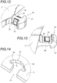
- the safety device (33) can also fulfill the role of centering of the centering device (29) and these two devices can be in the form of a single centering and safety device (29, 33).
- the male member (34) of the safety device (33) is in the form of a centering finger (30), the free end of which comprises an anchoring piece (37) extending transversely on each side from the free end of the centering finger (30).
- the anchor piece (37) is in the general form of an anchor-type hook and the female receiving member (35) has a general shape complementary to the anchor piece (37) and is open both in its upper face and in its lower face.
- the centering finger (30) has in the lower part lateral supports (38) extending laterally in prominence in order to support the furs (32) of the centering finger (30) when they are subjected to a directed vertical force down.
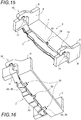
- the safety device (33) and the centering device (29) are separate.
- the centering finger (30) is a simple piece of general shape rectangular with lateral supports (38) for the furs (32), while the safety device (33) comprises two male members (34) in the form of hooks (39) the free part of which is bent upwards to penetrate from below in female receiving members (35) provided on the underside of the pivoting structure (5).
- the female receiving members (35) are in the form of simple housings (40) having an open face downwards.
- the male members (34) and the female receiving members (35) are provided offset laterally with respect to the centering device (29).
- the centering finger (30) and male members (34) extend in prominence from the end platform (2) in the lower part thereof in the direction of the pivoting structure (5).
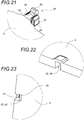
- the safety device (33) and the centering device (29) are in the form of a single centering and safety device (29, 33).
- the male member (34) of the safety device (33) is in the form of a centering finger (30), the free end of which has a hook (39) bent upward to penetrate. from below in a female receiving member (35) provided on the underside of the pivoting structure (5).
- the female receiving member (35) is in the form of a housing (40) having both an open face downward and an open face towards the end platform (2) to leave penetrate both the centering finger (30) and the male member (34).
- the housing (40) In its face opposite the end platform (2), the housing (40) has a retaining cleat (41) which extends downward from the upper face of the housing (40) in order to be engaged in traction or when pushed by the hook (39) in the event of a failure of one of the connecting members connecting the two end platforms (2) to the tie rod (3) in nominal mode.
- the safety device (33) and the centering device (29) are also held vertically upwards by the upper bottom of the housing (40).
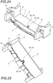
- the safety device (33) and the centering device (29) are in the form of a single centering and safety device (29, 33).
- the male member (34) of the safety device (33) is in the form of a centering finger (30) having transverse axes (42) in its middle part, these transverse axes (42) extending laterally from the middle part of the centering finger (30) through the flanges (32) of said centering finger (30).
- the safety device (33) and the centering device (29) thus adopt the general shape of a cross, the branches of which are located in a horizontal plane, the free parts of which are designed to come into reception in a female receiving member (35) provided on the underside of the pivoting structure (5).
- the female receiving member (35) is in the form of a housing (40) having a general shape of a cross complementary to the shape of the safety device (33) and of the centering device (29), with a longitudinal part (43) and transverse parts (44) extending in a horizontal plane on each side of the longitudinal part (43).
- This cross-shaped housing (40) has both an open face downward and an open face towards the end platform (2) to allow both the centering finger (30) and the male organ (34).
- the transverse axes (42) of the safety device (33) are found in traction or push contact in the transverse parts (44) of the housing (40).
- the transverse axes (42) of the safety device (33) are also retained vertically upwards by the upper bottom of the housing (40).
- the female receiving member (35) has dimensions slightly larger than those of the female receiving member (35) of the safety device (33) so that these members (34, 35) are not in contact only in the event of failure of one of the connecting members connecting the two end platforms (2) to the tie rod (3) in nominal mode.
- each connection system (10) also comprises an additional safety device (45) which prevents the transverse disengagement of the hooks (15) open downwards with the hooks (11) open to the top.
- an additional safety device (45) is shown in the figures 7 to 9 .
- the additional safety device (45) comprises an upper stop (46) provided on the external flank of one of the hooks (11) open upwards, preferably at the level of its part (13) protruding upwards.
- This upper stopper (46) has an upper part (47) extending upwards above said hook (11) open upwards so as to form a lateral stopper for the hook (15). open downwards intended to engage with said hook (11) open upwards.
- the internal lateral face of said upper part (47) extending upwards abuts against the external lateral face of the hook (15) open downwards when the pivoting structure (5) is pivoted in the transport position.
- the upper stopper (46) can also have a lower part (48) extending downwards in order to form a front stopper for the locking hook (24) when it is in the unlocked position.
- the additional safety device (45) also comprises a bottom stop (49) provided on the external flank of the other hook (11) open upwards, preferably at the level of its part (13 ) protruding upwards.
- This low stop (49) has no part projecting above said hook (11) open upwards so that the pivoting structure (5) can pass over it without a of its hooks (15) open towards the bottom does not come into abutment against the bottom stop (49) when the pivoting structure (5) is pivoted.
- the lower stopper (49) however has a longitudinal part (50) extending forwards or backwards which abuts against the external lateral face of the hook (15) open downwards when the pivoting structure (5) descends to the transport position.
- the lower stopper (49) can also have a lower part (48) extending downwards in order to form a front stopper for the locking hook (24) when that -this is in the unlocked position.
- the side on which the upper stopper (46) and the lower stopper (49) are mounted on the end platform (2) depends of course on the direction of rotation in which the pivoting structure (5) is pivoted in the transport position, the pivoting structure (5), when in the high position, pivoting above the low stop (49) to come into abutment against the high stop (46).
- the end platform (2) abuts against the lower stopper (49) only when it has come back down to its lower position. It is then kept centered by its two stops (46, 49) redundantly with the centering device (29)
- the upper stopper (46) and the lower stopper (49) are preferably bolted to the external side face of their respective hook (11) open upwards.
- Each link system (10) thus offers maximum security.
- each connection system (10) since each connection system (10) only includes hooks (11, 15) in the upper part, the tie rod (3) takes up the torque generated by the pivoting structure (5) carrying the road load.
Landscapes
- Engineering & Computer Science (AREA)
- Transportation (AREA)
- Mechanical Engineering (AREA)
- Handcart (AREA)
- Vehicle Cleaning, Maintenance, Repair, Refitting, And Outriggers (AREA)
- Connection Of Plates (AREA)
Applications Claiming Priority (1)
| Application Number | Priority Date | Filing Date | Title |
|---|---|---|---|
| FR1857110A FR3084319B1 (fr) | 2018-07-30 | 2018-07-30 | Systeme de liaison pour wagon de transport combine rail/route |
Publications (2)
| Publication Number | Publication Date |
|---|---|
| EP3604073A1 true EP3604073A1 (de) | 2020-02-05 |
| EP3604073B1 EP3604073B1 (de) | 2020-11-04 |
Family
ID=63896366
Family Applications (1)
| Application Number | Title | Priority Date | Filing Date |
|---|---|---|---|
| EP19182330.1A Active EP3604073B1 (de) | 2018-07-30 | 2019-06-25 | Verbindungssystem für waggon für kombinierten transport schiene/strasse |
Country Status (4)
| Country | Link |
|---|---|
| EP (1) | EP3604073B1 (de) |
| CN (2) | CN110775087A (de) |
| FR (1) | FR3084319B1 (de) |
| HU (1) | HUE052724T2 (de) |
Cited By (3)
| Publication number | Priority date | Publication date | Assignee | Title |
|---|---|---|---|---|
| WO2021169172A1 (zh) * | 2020-02-28 | 2021-09-02 | 中车齐齐哈尔车辆有限公司 | 一种驮背车及其车体 |
| KR20230039216A (ko) * | 2021-09-14 | 2023-03-21 | 한국기계연구원 | 무빙트레일러를 이용한 철도물류 피기백 화차용 이송설비 및 방법 |
| KR20230039217A (ko) * | 2021-09-14 | 2023-03-21 | 한국기계연구원 | 셔틀카를 이용한 철도물류 피기백 화차용 이송설비 및 방법 |
Families Citing this family (8)
| Publication number | Priority date | Publication date | Assignee | Title |
|---|---|---|---|---|
| CN111301461B (zh) * | 2020-02-28 | 2024-12-03 | 中车齐齐哈尔车辆有限公司 | 一种驮背车及其底架组成 |
| CN111137315B (zh) * | 2020-02-28 | 2025-01-10 | 中车齐齐哈尔车辆有限公司 | 一种平移式驮背运输系统 |
| CN111186451B (zh) * | 2020-02-28 | 2024-10-15 | 中车齐齐哈尔车辆有限公司 | 一种驮背车及托部的横向止挡机构 |
| CN111409660B (zh) * | 2020-02-28 | 2025-01-14 | 中车齐齐哈尔车辆有限公司 | 一种驮背车的关节底架 |
| CN111301447A (zh) * | 2020-02-28 | 2020-06-19 | 中车齐齐哈尔车辆有限公司 | 一种驮背车的托部 |
| CN111376938B (zh) * | 2020-02-28 | 2024-05-28 | 北京驮丰高新科技股份有限公司 | 一种驮背车的端部底架 |
| CN111301445B (zh) * | 2020-02-28 | 2024-08-20 | 中车齐齐哈尔车辆有限公司 | 一种驮背车及其车体 |
| CN111301448B (zh) * | 2020-02-28 | 2024-05-28 | 北京驮丰高新科技股份有限公司 | 一种托部的锁闭机构及驮背车 |
Citations (4)
| Publication number | Priority date | Publication date | Assignee | Title |
|---|---|---|---|---|
| EP1292478A1 (de) | 2000-06-21 | 2003-03-19 | Lohr Industrie S.A. | Waggon für den kombinierten schienen/strassen- transpport mit zwei endseitigen plattformen, die eine drehbare tragstruktur für den lastkraftwagen tragen |
| WO2010120236A1 (en) * | 2009-04-16 | 2010-10-21 | K Technology Ab | A railway wagon and a method of its loading |
| CN105644570A (zh) * | 2016-03-10 | 2016-06-08 | 中车齐齐哈尔车辆有限公司 | 一种驮背式运输用新型铁路货车 |
| EP3269612A1 (de) * | 2010-06-04 | 2018-01-17 | Lohr Industrie | Schienentransportfahrzeug mit schnittstelle zur kompensation der höhe über dem boden und dies insbesondere abhängig vom zu transportierenden ladegewicht |
-
2018
- 2018-07-30 FR FR1857110A patent/FR3084319B1/fr not_active Expired - Fee Related
- 2018-09-26 CN CN201811122348.2A patent/CN110775087A/zh active Pending
- 2018-09-26 CN CN201821569669.2U patent/CN209505744U/zh not_active Expired - Fee Related
-
2019
- 2019-06-25 EP EP19182330.1A patent/EP3604073B1/de active Active
- 2019-06-25 HU HUE19182330A patent/HUE052724T2/hu unknown
Patent Citations (4)
| Publication number | Priority date | Publication date | Assignee | Title |
|---|---|---|---|---|
| EP1292478A1 (de) | 2000-06-21 | 2003-03-19 | Lohr Industrie S.A. | Waggon für den kombinierten schienen/strassen- transpport mit zwei endseitigen plattformen, die eine drehbare tragstruktur für den lastkraftwagen tragen |
| WO2010120236A1 (en) * | 2009-04-16 | 2010-10-21 | K Technology Ab | A railway wagon and a method of its loading |
| EP3269612A1 (de) * | 2010-06-04 | 2018-01-17 | Lohr Industrie | Schienentransportfahrzeug mit schnittstelle zur kompensation der höhe über dem boden und dies insbesondere abhängig vom zu transportierenden ladegewicht |
| CN105644570A (zh) * | 2016-03-10 | 2016-06-08 | 中车齐齐哈尔车辆有限公司 | 一种驮背式运输用新型铁路货车 |
Cited By (5)
| Publication number | Priority date | Publication date | Assignee | Title |
|---|---|---|---|---|
| WO2021169172A1 (zh) * | 2020-02-28 | 2021-09-02 | 中车齐齐哈尔车辆有限公司 | 一种驮背车及其车体 |
| KR20230039216A (ko) * | 2021-09-14 | 2023-03-21 | 한국기계연구원 | 무빙트레일러를 이용한 철도물류 피기백 화차용 이송설비 및 방법 |
| KR20230039217A (ko) * | 2021-09-14 | 2023-03-21 | 한국기계연구원 | 셔틀카를 이용한 철도물류 피기백 화차용 이송설비 및 방법 |
| KR102575540B1 (ko) | 2021-09-14 | 2023-09-07 | 한국기계연구원 | 셔틀카를 이용한 철도물류 피기백 화차용 이송설비 및 방법 |
| KR102590808B1 (ko) | 2021-09-14 | 2023-10-19 | 한국기계연구원 | 무빙트레일러를 이용한 철도물류 피기백 화차용 이송설비 및 방법 |
Also Published As
| Publication number | Publication date |
|---|---|
| FR3084319A1 (fr) | 2020-01-31 |
| CN110775087A (zh) | 2020-02-11 |
| EP3604073B1 (de) | 2020-11-04 |
| HUE052724T2 (hu) | 2021-05-28 |
| FR3084319B1 (fr) | 2020-07-24 |
| CN209505744U (zh) | 2019-10-18 |
Similar Documents
| Publication | Publication Date | Title |
|---|---|---|
| EP3604073B1 (de) | Verbindungssystem für waggon für kombinierten transport schiene/strasse | |
| EP2544938B1 (de) | Entfernbare stützende querträger mit einem in der höhe anpassbaren fünften rad zum stützen eines sattelaufliegers während dessen beladung, zugtransport und entladung | |
| EP1292476B1 (de) | Transport- und scrägverladesystem für waggons in einem bahnhof für den kombinierten schienen-/strassen- transport und zugehöriges verfahren | |
| EP1292478B1 (de) | Waggon für den kombinierten schienen/strassen- transpport mit zwei endseitigen plattformen, die eine drehbare tragstruktur für den lastkraftwagen tragen | |
| WO2019158557A1 (fr) | Came de blocage d'un crochet de charge et dispositif d'accrochage comportant une telle came | |
| EP2173642B1 (de) | Gepäckbehälter | |
| EP3752444B1 (de) | Lasttragende vorrichtung für eine hubvorrichtung | |
| EP0425370B1 (de) | Abnehmbares Zwischenstück für die Verbindung und Handhabung von Containern auf Fahrzeugen und entsprechendes Fahrzeug | |
| EP2392734A1 (de) | Fahrbahntrennmodul aus Beton und Trennbarriere, die mehrere Module dieses Typs umfasst | |
| EP3393882B1 (de) | System zur immobilisierung eines sattelaufliegerachszapfens auf einem transportfahrzeug | |
| WO2020104908A2 (fr) | Conteneur équipé d'un système de verrouillage de conteneur | |
| EP3945003B1 (de) | Klemmvorrichtung für ein abnehmbares schutzgeländer, die an einer stufe eines wagens eines schienenfahrzeugs befestigt ist, und mit einer solchen klemmvorrichtung ausgestattetes schutzgeländer | |
| EP1612161A1 (de) | Vorrichtung zum Unterstützen und Transportieren von steifen Platten | |
| EP3677484B1 (de) | Verbindungsvorrichtung zwischen dem zuganker und den plattformen am ende eines transportwaggons für den kombinierten schienen-strassen-verkehr | |
| FR2541211A1 (fr) | Dispositif-support rabattable pour wagons, remorques routieres et similaires | |
| EP3880514B1 (de) | Lastträger zur positionierung, verriegelung und entriegelung auf einer tragenden struktur durch eine geeignete anordnung | |
| WO2013098503A1 (fr) | Wagon de transport de véhicules, notamment pour un système de transport rail/route | |
| FR3139323A1 (fr) | Dipositif permettant l’accroche d’un cable sur une palette pour permettre son chargement ou dechargement | |
| FR3022231A1 (fr) | Dispositif de manutention d'une charge, notamment d'un element de batterie de vehicule sous-marin | |
| WO2023118714A1 (fr) | Systeme amelioré de support d'emballage de transport de matières radioactives, configuré pour permettre son pivotement d'une position horizontale de transport à une position verticale d'exploitation | |
| FR2979623A1 (fr) | Dispositif detrompeur pour l'accrochage de moyens permettant le levage d'objets particulierement lourds et encombrants, en vue de leur deplacement, et objets equipes d'un tel dispositif detrompeur | |
| FR2815005A1 (fr) | Dispositif de securite limitant le debattement du pivot de selette d'une semi-remorque transportee sur un wagon ferroviaire | |
| WO2012127331A1 (fr) | Dispositif de commande d'accessoires pour porte-conteneur |
Legal Events
| Date | Code | Title | Description |
|---|---|---|---|
| PUAI | Public reference made under article 153(3) epc to a published international application that has entered the european phase |
Free format text: ORIGINAL CODE: 0009012 |
|
| STAA | Information on the status of an ep patent application or granted ep patent |
Free format text: STATUS: THE APPLICATION HAS BEEN PUBLISHED |
|
| AK | Designated contracting states |
Kind code of ref document: A1 Designated state(s): AL AT BE BG CH CY CZ DE DK EE ES FI FR GB GR HR HU IE IS IT LI LT LU LV MC MK MT NL NO PL PT RO RS SE SI SK SM TR |
|
| AX | Request for extension of the european patent |
Extension state: BA ME |
|
| STAA | Information on the status of an ep patent application or granted ep patent |
Free format text: STATUS: REQUEST FOR EXAMINATION WAS MADE |
|
| 17P | Request for examination filed |
Effective date: 20200316 |
|
| RBV | Designated contracting states (corrected) |
Designated state(s): AL AT BE BG CH CY CZ DE DK EE ES FI FR GB GR HR HU IE IS IT LI LT LU LV MC MK MT NL NO PL PT RO RS SE SI SK SM TR |
|
| GRAP | Despatch of communication of intention to grant a patent |
Free format text: ORIGINAL CODE: EPIDOSNIGR1 |
|
| STAA | Information on the status of an ep patent application or granted ep patent |
Free format text: STATUS: GRANT OF PATENT IS INTENDED |
|
| INTG | Intention to grant announced |
Effective date: 20200723 |
|
| GRAS | Grant fee paid |
Free format text: ORIGINAL CODE: EPIDOSNIGR3 |
|
| GRAA | (expected) grant |
Free format text: ORIGINAL CODE: 0009210 |
|
| STAA | Information on the status of an ep patent application or granted ep patent |
Free format text: STATUS: THE PATENT HAS BEEN GRANTED |
|
| AK | Designated contracting states |
Kind code of ref document: B1 Designated state(s): AL AT BE BG CH CY CZ DE DK EE ES FI FR GB GR HR HU IE IS IT LI LT LU LV MC MK MT NL NO PL PT RO RS SE SI SK SM TR |
|
| REG | Reference to a national code |
Ref country code: GB Ref legal event code: FG4D Free format text: NOT ENGLISH |
|
| REG | Reference to a national code |
Ref country code: CH Ref legal event code: EP |
|
| REG | Reference to a national code |
Ref country code: AT Ref legal event code: REF Ref document number: 1330458 Country of ref document: AT Kind code of ref document: T Effective date: 20201115 |
|
| REG | Reference to a national code |
Ref country code: IE Ref legal event code: FG4D Free format text: LANGUAGE OF EP DOCUMENT: FRENCH |
|
| REG | Reference to a national code |
Ref country code: DE Ref legal event code: R096 Ref document number: 602019001193 Country of ref document: DE |
|
| REG | Reference to a national code |
Ref country code: NL Ref legal event code: MP Effective date: 20201104 |
|
| REG | Reference to a national code |
Ref country code: AT Ref legal event code: MK05 Ref document number: 1330458 Country of ref document: AT Kind code of ref document: T Effective date: 20201104 |
|
| PG25 | Lapsed in a contracting state [announced via postgrant information from national office to epo] |
Ref country code: NO Free format text: LAPSE BECAUSE OF FAILURE TO SUBMIT A TRANSLATION OF THE DESCRIPTION OR TO PAY THE FEE WITHIN THE PRESCRIBED TIME-LIMIT Effective date: 20210204 Ref country code: GR Free format text: LAPSE BECAUSE OF FAILURE TO SUBMIT A TRANSLATION OF THE DESCRIPTION OR TO PAY THE FEE WITHIN THE PRESCRIBED TIME-LIMIT Effective date: 20210205 Ref country code: FI Free format text: LAPSE BECAUSE OF FAILURE TO SUBMIT A TRANSLATION OF THE DESCRIPTION OR TO PAY THE FEE WITHIN THE PRESCRIBED TIME-LIMIT Effective date: 20201104 Ref country code: PT Free format text: LAPSE BECAUSE OF FAILURE TO SUBMIT A TRANSLATION OF THE DESCRIPTION OR TO PAY THE FEE WITHIN THE PRESCRIBED TIME-LIMIT Effective date: 20210304 Ref country code: RS Free format text: LAPSE BECAUSE OF FAILURE TO SUBMIT A TRANSLATION OF THE DESCRIPTION OR TO PAY THE FEE WITHIN THE PRESCRIBED TIME-LIMIT Effective date: 20201104 |
|
| REG | Reference to a national code |
Ref country code: HU Ref legal event code: AG4A Ref document number: E052724 Country of ref document: HU |
|
| PG25 | Lapsed in a contracting state [announced via postgrant information from national office to epo] |
Ref country code: ES Free format text: LAPSE BECAUSE OF FAILURE TO SUBMIT A TRANSLATION OF THE DESCRIPTION OR TO PAY THE FEE WITHIN THE PRESCRIBED TIME-LIMIT Effective date: 20201104 Ref country code: AT Free format text: LAPSE BECAUSE OF FAILURE TO SUBMIT A TRANSLATION OF THE DESCRIPTION OR TO PAY THE FEE WITHIN THE PRESCRIBED TIME-LIMIT Effective date: 20201104 Ref country code: LV Free format text: LAPSE BECAUSE OF FAILURE TO SUBMIT A TRANSLATION OF THE DESCRIPTION OR TO PAY THE FEE WITHIN THE PRESCRIBED TIME-LIMIT Effective date: 20201104 Ref country code: PL Free format text: LAPSE BECAUSE OF FAILURE TO SUBMIT A TRANSLATION OF THE DESCRIPTION OR TO PAY THE FEE WITHIN THE PRESCRIBED TIME-LIMIT Effective date: 20201104 Ref country code: IS Free format text: LAPSE BECAUSE OF FAILURE TO SUBMIT A TRANSLATION OF THE DESCRIPTION OR TO PAY THE FEE WITHIN THE PRESCRIBED TIME-LIMIT Effective date: 20210304 Ref country code: SE Free format text: LAPSE BECAUSE OF FAILURE TO SUBMIT A TRANSLATION OF THE DESCRIPTION OR TO PAY THE FEE WITHIN THE PRESCRIBED TIME-LIMIT Effective date: 20201104 Ref country code: BG Free format text: LAPSE BECAUSE OF FAILURE TO SUBMIT A TRANSLATION OF THE DESCRIPTION OR TO PAY THE FEE WITHIN THE PRESCRIBED TIME-LIMIT Effective date: 20210204 |
|
| REG | Reference to a national code |
Ref country code: LT Ref legal event code: MG9D |
|
| PG25 | Lapsed in a contracting state [announced via postgrant information from national office to epo] |
Ref country code: HR Free format text: LAPSE BECAUSE OF FAILURE TO SUBMIT A TRANSLATION OF THE DESCRIPTION OR TO PAY THE FEE WITHIN THE PRESCRIBED TIME-LIMIT Effective date: 20201104 |
|
| PG25 | Lapsed in a contracting state [announced via postgrant information from national office to epo] |
Ref country code: SM Free format text: LAPSE BECAUSE OF FAILURE TO SUBMIT A TRANSLATION OF THE DESCRIPTION OR TO PAY THE FEE WITHIN THE PRESCRIBED TIME-LIMIT Effective date: 20201104 Ref country code: SK Free format text: LAPSE BECAUSE OF FAILURE TO SUBMIT A TRANSLATION OF THE DESCRIPTION OR TO PAY THE FEE WITHIN THE PRESCRIBED TIME-LIMIT Effective date: 20201104 Ref country code: EE Free format text: LAPSE BECAUSE OF FAILURE TO SUBMIT A TRANSLATION OF THE DESCRIPTION OR TO PAY THE FEE WITHIN THE PRESCRIBED TIME-LIMIT Effective date: 20201104 Ref country code: CZ Free format text: LAPSE BECAUSE OF FAILURE TO SUBMIT A TRANSLATION OF THE DESCRIPTION OR TO PAY THE FEE WITHIN THE PRESCRIBED TIME-LIMIT Effective date: 20201104 Ref country code: LT Free format text: LAPSE BECAUSE OF FAILURE TO SUBMIT A TRANSLATION OF THE DESCRIPTION OR TO PAY THE FEE WITHIN THE PRESCRIBED TIME-LIMIT Effective date: 20201104 Ref country code: RO Free format text: LAPSE BECAUSE OF FAILURE TO SUBMIT A TRANSLATION OF THE DESCRIPTION OR TO PAY THE FEE WITHIN THE PRESCRIBED TIME-LIMIT Effective date: 20201104 |
|
| REG | Reference to a national code |
Ref country code: DE Ref legal event code: R097 Ref document number: 602019001193 Country of ref document: DE |
|
| PG25 | Lapsed in a contracting state [announced via postgrant information from national office to epo] |
Ref country code: DK Free format text: LAPSE BECAUSE OF FAILURE TO SUBMIT A TRANSLATION OF THE DESCRIPTION OR TO PAY THE FEE WITHIN THE PRESCRIBED TIME-LIMIT Effective date: 20201104 |
|
| PLBE | No opposition filed within time limit |
Free format text: ORIGINAL CODE: 0009261 |
|
| STAA | Information on the status of an ep patent application or granted ep patent |
Free format text: STATUS: NO OPPOSITION FILED WITHIN TIME LIMIT |
|
| 26N | No opposition filed |
Effective date: 20210805 |
|
| PG25 | Lapsed in a contracting state [announced via postgrant information from national office to epo] |
Ref country code: NL Free format text: LAPSE BECAUSE OF FAILURE TO SUBMIT A TRANSLATION OF THE DESCRIPTION OR TO PAY THE FEE WITHIN THE PRESCRIBED TIME-LIMIT Effective date: 20201104 Ref country code: AL Free format text: LAPSE BECAUSE OF FAILURE TO SUBMIT A TRANSLATION OF THE DESCRIPTION OR TO PAY THE FEE WITHIN THE PRESCRIBED TIME-LIMIT Effective date: 20201104 |
|
| PG25 | Lapsed in a contracting state [announced via postgrant information from national office to epo] |
Ref country code: SI Free format text: LAPSE BECAUSE OF FAILURE TO SUBMIT A TRANSLATION OF THE DESCRIPTION OR TO PAY THE FEE WITHIN THE PRESCRIBED TIME-LIMIT Effective date: 20201104 |
|
| PG25 | Lapsed in a contracting state [announced via postgrant information from national office to epo] |
Ref country code: MC Free format text: LAPSE BECAUSE OF FAILURE TO SUBMIT A TRANSLATION OF THE DESCRIPTION OR TO PAY THE FEE WITHIN THE PRESCRIBED TIME-LIMIT Effective date: 20201104 |
|
| REG | Reference to a national code |
Ref country code: BE Ref legal event code: MM Effective date: 20210630 |
|
| PG25 | Lapsed in a contracting state [announced via postgrant information from national office to epo] |
Ref country code: LU Free format text: LAPSE BECAUSE OF NON-PAYMENT OF DUE FEES Effective date: 20210625 |
|
| PG25 | Lapsed in a contracting state [announced via postgrant information from national office to epo] |
Ref country code: IE Free format text: LAPSE BECAUSE OF NON-PAYMENT OF DUE FEES Effective date: 20210625 |
|
| PG25 | Lapsed in a contracting state [announced via postgrant information from national office to epo] |
Ref country code: IS Free format text: LAPSE BECAUSE OF FAILURE TO SUBMIT A TRANSLATION OF THE DESCRIPTION OR TO PAY THE FEE WITHIN THE PRESCRIBED TIME-LIMIT Effective date: 20210304 |
|
| PG25 | Lapsed in a contracting state [announced via postgrant information from national office to epo] |
Ref country code: BE Free format text: LAPSE BECAUSE OF NON-PAYMENT OF DUE FEES Effective date: 20210630 |
|
| REG | Reference to a national code |
Ref country code: CH Ref legal event code: PL |
|
| PG25 | Lapsed in a contracting state [announced via postgrant information from national office to epo] |
Ref country code: LI Free format text: LAPSE BECAUSE OF NON-PAYMENT OF DUE FEES Effective date: 20220630 Ref country code: CH Free format text: LAPSE BECAUSE OF NON-PAYMENT OF DUE FEES Effective date: 20220630 |
|
| PG25 | Lapsed in a contracting state [announced via postgrant information from national office to epo] |
Ref country code: CY Free format text: LAPSE BECAUSE OF FAILURE TO SUBMIT A TRANSLATION OF THE DESCRIPTION OR TO PAY THE FEE WITHIN THE PRESCRIBED TIME-LIMIT Effective date: 20201104 |
|
| P01 | Opt-out of the competence of the unified patent court (upc) registered |
Effective date: 20230527 |
|
| GBPC | Gb: european patent ceased through non-payment of renewal fee |
Effective date: 20230625 |
|
| PG25 | Lapsed in a contracting state [announced via postgrant information from national office to epo] |
Ref country code: MK Free format text: LAPSE BECAUSE OF FAILURE TO SUBMIT A TRANSLATION OF THE DESCRIPTION OR TO PAY THE FEE WITHIN THE PRESCRIBED TIME-LIMIT Effective date: 20201104 Ref country code: GB Free format text: LAPSE BECAUSE OF NON-PAYMENT OF DUE FEES Effective date: 20230625 |
|
| PG25 | Lapsed in a contracting state [announced via postgrant information from national office to epo] |
Ref country code: TR Free format text: LAPSE BECAUSE OF FAILURE TO SUBMIT A TRANSLATION OF THE DESCRIPTION OR TO PAY THE FEE WITHIN THE PRESCRIBED TIME-LIMIT Effective date: 20201104 |
|
| PGFP | Annual fee paid to national office [announced via postgrant information from national office to epo] |
Ref country code: DE Payment date: 20240613 Year of fee payment: 6 |
|
| PGFP | Annual fee paid to national office [announced via postgrant information from national office to epo] |
Ref country code: HU Payment date: 20240605 Year of fee payment: 6 |
|
| PG25 | Lapsed in a contracting state [announced via postgrant information from national office to epo] |
Ref country code: MT Free format text: LAPSE BECAUSE OF FAILURE TO SUBMIT A TRANSLATION OF THE DESCRIPTION OR TO PAY THE FEE WITHIN THE PRESCRIBED TIME-LIMIT Effective date: 20201104 |
|
| PGFP | Annual fee paid to national office [announced via postgrant information from national office to epo] |
Ref country code: IT Payment date: 20240607 Year of fee payment: 6 |
|
| PGFP | Annual fee paid to national office [announced via postgrant information from national office to epo] |
Ref country code: FR Payment date: 20250619 Year of fee payment: 7 |
|
| REG | Reference to a national code |
Ref country code: DE Ref legal event code: R119 Ref document number: 602019001193 Country of ref document: DE |
|
| PG25 | Lapsed in a contracting state [announced via postgrant information from national office to epo] |
Ref country code: HU Free format text: LAPSE BECAUSE OF NON-PAYMENT OF DUE FEES Effective date: 20250626 |
|
| PG25 | Lapsed in a contracting state [announced via postgrant information from national office to epo] |
Ref country code: DE Free format text: LAPSE BECAUSE OF NON-PAYMENT OF DUE FEES Effective date: 20260101 |
|
| PG25 | Lapsed in a contracting state [announced via postgrant information from national office to epo] |
Ref country code: IT Free format text: LAPSE BECAUSE OF NON-PAYMENT OF DUE FEES Effective date: 20250625 |