EP3603453A1 - Motorbetriebener zurücklehnmechanismus für einen theatersitz auf geneigtem boden - Google Patents
Motorbetriebener zurücklehnmechanismus für einen theatersitz auf geneigtem boden Download PDFInfo
- Publication number
- EP3603453A1 EP3603453A1 EP19198111.7A EP19198111A EP3603453A1 EP 3603453 A1 EP3603453 A1 EP 3603453A1 EP 19198111 A EP19198111 A EP 19198111A EP 3603453 A1 EP3603453 A1 EP 3603453A1
- Authority
- EP
- European Patent Office
- Prior art keywords
- link
- pair
- links
- attached
- rear pivot
- Prior art date
- Legal status (The legal status is an assumption and is not a legal conclusion. Google has not performed a legal analysis and makes no representation as to the accuracy of the status listed.)
- Withdrawn
Links
- 230000007246 mechanism Effects 0.000 title claims abstract description 86
- 230000007704 transition Effects 0.000 abstract description 3
- 230000000712 assembly Effects 0.000 description 4
- 238000000429 assembly Methods 0.000 description 4
- 230000008901 benefit Effects 0.000 description 4
- 241000711981 Sais Species 0.000 description 3
- 230000003213 activating effect Effects 0.000 description 1
- 230000004913 activation Effects 0.000 description 1
- 238000004140 cleaning Methods 0.000 description 1
- 230000003247 decreasing effect Effects 0.000 description 1
Images


Classifications
-
- B—PERFORMING OPERATIONS; TRANSPORTING
- B60—VEHICLES IN GENERAL
- B60N—SEATS SPECIALLY ADAPTED FOR VEHICLES; VEHICLE PASSENGER ACCOMMODATION NOT OTHERWISE PROVIDED FOR
- B60N2/00—Seats specially adapted for vehicles; Arrangement or mounting of seats in vehicles
- B60N2/02—Seats specially adapted for vehicles; Arrangement or mounting of seats in vehicles the seat or part thereof being movable, e.g. adjustable
- B60N2/22—Seats specially adapted for vehicles; Arrangement or mounting of seats in vehicles the seat or part thereof being movable, e.g. adjustable the back-rest being adjustable
- B60N2/225—Seats specially adapted for vehicles; Arrangement or mounting of seats in vehicles the seat or part thereof being movable, e.g. adjustable the back-rest being adjustable by cycloidal or planetary mechanisms
- B60N2/2252—Seats specially adapted for vehicles; Arrangement or mounting of seats in vehicles the seat or part thereof being movable, e.g. adjustable the back-rest being adjustable by cycloidal or planetary mechanisms in which the central axis of the gearing lies inside the periphery of an orbital gear, e.g. one gear without sun gear
-
- A—HUMAN NECESSITIES
- A47—FURNITURE; DOMESTIC ARTICLES OR APPLIANCES; COFFEE MILLS; SPICE MILLS; SUCTION CLEANERS IN GENERAL
- A47C—CHAIRS; SOFAS; BEDS
- A47C1/00—Chairs adapted for special purposes
- A47C1/02—Reclining or easy chairs
- A47C1/031—Reclining or easy chairs having coupled concurrently adjustable supporting parts
- A47C1/032—Reclining or easy chairs having coupled concurrently adjustable supporting parts the parts being movably-coupled seat and back-rest
- A47C1/03205—Reclining or easy chairs having coupled concurrently adjustable supporting parts the parts being movably-coupled seat and back-rest having adjustable and lockable inclination
- A47C1/03211—Reclining or easy chairs having coupled concurrently adjustable supporting parts the parts being movably-coupled seat and back-rest having adjustable and lockable inclination by electric motors
-
- A—HUMAN NECESSITIES
- A47—FURNITURE; DOMESTIC ARTICLES OR APPLIANCES; COFFEE MILLS; SPICE MILLS; SUCTION CLEANERS IN GENERAL
- A47C—CHAIRS; SOFAS; BEDS
- A47C1/00—Chairs adapted for special purposes
- A47C1/02—Reclining or easy chairs
- A47C1/031—Reclining or easy chairs having coupled concurrently adjustable supporting parts
- A47C1/034—Reclining or easy chairs having coupled concurrently adjustable supporting parts the parts including a leg-rest or foot-rest
- A47C1/0342—Reclining or easy chairs having coupled concurrently adjustable supporting parts the parts including a leg-rest or foot-rest in combination with movable backrest-seat unit or back-rest
- A47C1/0345—Reclining or easy chairs having coupled concurrently adjustable supporting parts the parts including a leg-rest or foot-rest in combination with movable backrest-seat unit or back-rest characterised by foot-rests actuated by lazy-tongs
-
- A—HUMAN NECESSITIES
- A47—FURNITURE; DOMESTIC ARTICLES OR APPLIANCES; COFFEE MILLS; SPICE MILLS; SUCTION CLEANERS IN GENERAL
- A47C—CHAIRS; SOFAS; BEDS
- A47C1/00—Chairs adapted for special purposes
- A47C1/12—Theatre, auditorium, or similar chairs
-
- B—PERFORMING OPERATIONS; TRANSPORTING
- B60—VEHICLES IN GENERAL
- B60N—SEATS SPECIALLY ADAPTED FOR VEHICLES; VEHICLE PASSENGER ACCOMMODATION NOT OTHERWISE PROVIDED FOR
- B60N2/00—Seats specially adapted for vehicles; Arrangement or mounting of seats in vehicles
- B60N2/02—Seats specially adapted for vehicles; Arrangement or mounting of seats in vehicles the seat or part thereof being movable, e.g. adjustable
- B60N2/0224—Non-manual adjustments, e.g. with electrical operation
- B60N2/02246—Electric motors therefor
- B60N2/02258—Electric motors therefor characterised by the mounting of the electric motor for adjusting the seat
-
- B—PERFORMING OPERATIONS; TRANSPORTING
- B60—VEHICLES IN GENERAL
- B60N—SEATS SPECIALLY ADAPTED FOR VEHICLES; VEHICLE PASSENGER ACCOMMODATION NOT OTHERWISE PROVIDED FOR
- B60N2/00—Seats specially adapted for vehicles; Arrangement or mounting of seats in vehicles
- B60N2/90—Details or parts not otherwise provided for
- B60N2/995—Lower-leg-rests, e.g. calf-rests
-
- B—PERFORMING OPERATIONS; TRANSPORTING
- B60—VEHICLES IN GENERAL
- B60N—SEATS SPECIALLY ADAPTED FOR VEHICLES; VEHICLE PASSENGER ACCOMMODATION NOT OTHERWISE PROVIDED FOR
- B60N2205/00—General mechanical or structural details
- B60N2205/50—Interlocking shaft arrangements transmitting movement between hinge mechanisms on both sides of a seat
Definitions
- the disclosure relates to a motor driven chair recline mechanism that can be advantageously mounted on sloped floors. More particularly, the disclosure relates to a motor driven recline mechanism for a theater seat.
- the theater seat includes a vertical back member and a seating member operatively connected to the back member, a base frame and a pair of opposed armrests.
- the back member is fixed relative to the seating member usually by a stanchion secured to the floor of the theater.
- the seat member and the back member are also connected to the pair of opposed armrests.
- the seating member usually pivots relative to the back member, between an upright position when unoccupied and a horizontal position when occupied by a user.
- Existing recline mechanisms for theater seats are based on designs intended for residential use where space is not an issue. Motorized recline mechanisms are common in residential recliner seats and have only recently become popular as a luxury option in theater venues.
- Typical residential recliners are not designed to accommodate sloped floors and have essential mechanical components (for example necessary linkage mechanism) that extend down from the seat all the way to floor level and have no capacity for lowering the rear of the recliner as is necessary when mounting on a non-leveled or sloped floor.
- essential mechanical components for example necessary linkage mechanism
- utilizing all the space under a seat for essential mechanical components makes cleaning under the recliner a difficult or impossible task.
- there is a code requiring a minimum clearance between rows in a theater that must be adhered to. Such a code limits the type of recline-type seats that can be used, the quantitative layout allowed for per seat, and, therefore, the number of seats that can be installed in a given space.
- There is a need for a seat assembly that provides the comfort of the recline aspect of a VIP chair but at the same time be compact from front to rear, with a small layout when the chair is open that falls generally within its own profile.
- the current disclosure provides a recline mechanism and its associated compact and comfort seat assembly that allows its mounting on leveled and on sloped floors.
- the seat assembly can be for example, a theater seat.
- the seat assembly may be an airplane seat, a bus seat, a train seat or a boat seat, etc.
- the recline mechanism can further include a linear actuator (30), a front motor drive tube (11a), and a rear motor drive tube (11b), wherein the front motor drive tube is attached to each of said pair of front pivot links (9) and the back motor drive tube is attached to the pair of rear pivot links (15), and wherein said linear actuator (30) is attached to said front motor drive tube (11b) by the front actuator attachment point (24) and to said rear motor drive (11b) by the rear actuator attachment point (26).
- a linear actuator (30) is attached to said front motor drive tube (11b) by the front actuator attachment point (24) and to said rear motor drive (11b) by the rear actuator attachment point (26).
- the seating assembly can further include a linear actuator (30), a front motor drive tube (11a), and a rear motor drive tube (11b), wherein the front motor drive tube is attached to each of said pair of front pivot links (9) and the back motor drive tube is attached to the pair of rear pivot links (15), and wherein said linear actuator (30) is attached to said front motor drive tube (11b) by the front actuator attachment point (24) and to said rear motor drive (11b) by the rear actuator attachment point (26).
- the seating assembly may be a theater seat, an airplane seat, a bus seat, a train seat or a boat seat.
- the seating assembly may be mounted on a sloped surface or on a leveled or flat surface.
- the recline mechanism can further include a linear actuator (30), a front motor drive tube (11a), and a rear motor drive tube (11b), wherein the front motor drive tube is attached to each of said pair of front pivot links (9) and the back motor drive tube is attached to the pair of rear pivot links (15), and wherein said linear actuator (30) is attached to said front motor drive tube (11b) by the front actuator attachment point (24) and to said rear motor drive (11b) by the rear actuator attachment point (26) and also further includes a seat frame assembly (55) connected to the seat rail bracket (10), a back frame assembly (50) connected to the seat frame assembly (55).
- the recline mechanism may be part of a seating assembly that also includes an Ottoman assembly (60, 65) so as to provide a foot rest to the user of the seat assembly such that the Ottoman assembly is attached to the seat frame by links via pivotal connection points.
- An additional objective of the invention is to provide recline mechanism for a seating assembly having, a pair of seat rail brackets (10); a pair of front pivot links (9), each of said pair of front pivot links attached to one of sais pair of seat rail bracket (10) on opposite sides; a pair of rear pivot upper lift link configured to control the motion of a rear end of the seating assembly wherein each of said pair of rear pivot upper lift links is attached at its upper end to one of said pair of seat rail brackets (10); a pair of rear pivot links (15) each attached at its upper end to the lower end of one of said pair of rear pivot upper lift links (13); a pair of carrier links (12), each of said carrier links attached to one of said pair of front pivot links (9) and to the lower end of one of said pair of rear pivot links (15); and a pair of rear pivot upper lift control links (14), each of said rear pivot upper lift control link attached at its upper end to one of said pivot upper lift link (13) and at its lower end to one of said carrier link (12); and a linear actuator (30), a front motor drive tube (
- a recline mechanism including a linear actuator assembly including a motor that is attached to a motor drive tube (11) at one end where the motor drive tube (11) is rigidly attached at the lower end to the rear pivot link (9) and at the other end to a second motor drive tube (11) which is rigidly attached to the rear pivot link (15), and such that the linear actuator is configured to move at both ends.
- the linear actuator provided by the current disclosure is not rigidly fixed to the carrier link (or base) at one end, but is allowed to move at both ends, a configuration that allows the motor to more efficiently articulate the seating assembly by avoiding loses due to poor angular position of the driving forces.
- the current disclosure provides a recline mechanism 100 and a seating assembly 200 including the recline mechanism 100 as depicted in Figures 1 -17 .
- Seating assembly is compact from front to rear, has a limited layout when the chair is open that falls within the seating assembly's own profile.
- the seating assembly is a theater seat.
- the recline mechanism of the current invention is not limited to theater seats, but can also be used in connection with a train seat, a bus seat, a boat seat, an airplane seat, etc.
- the current disclosure also provides a recline linkage mechanism suitable for use in seating assemblies anchored on flat/leveled or on sloped floors of varying degrees.
- the recline mechanism may be driven by a linear actuator or motor that is attached at both ends to a moving linkage, wherein the links move together in unison to operate the seating assembly.
- the motor driven recline mechanism of the current invention is particularly advantageous because a useable force is applied at two different locations in the linkage system so that when the links are in an inefficient position at one end, the links at the other end compensates. This aspect is different from prior art recline mechanisms and seating assemblies which are designed such that the linear actuator/motor is anchored to a stationary point at one end only. With the current mechanism, both front and rear pivot links are effectively being controlled.
- the current invention is not limited to use a motor but any linear actuator including a gas cylinder, a spring, etc. may be used with the recline mechanism of the current invention..
- the recline mechanism according to the current invention is unique in several aspects.
- the compactness of the rear of the linkage allows the mechanism to be used on a sloped floor application.
- the use of a linear actuator as contemplated in the design of the current recline mechanism allow for infinitely adjustable control between the closed position and reclined position.
- the linear actuator can be attached to moving linkage at both ends to make full use of the motor stroke and compensates for changing angular forces.
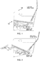
- the recline mechanism 100 affords the seating assembly various configurations: 1- normal unoccupied position, in which the seating member is in an upright position and the back member is in the upright position as shown in Figures 1 , 7 and 11 ; 2- occupied position, in which the seating member is in a down/closed position and the back member is in a full recline position as shown in Figures 2 , 8 and 12 .
- an embodiment of the motor driven sloped floor recline mechanism 100 of the current invention is used in connection with a seating assembly 200 comprising a seating member or seat frame 55; a pair of side panels or side arms on opposite sides of the seating member (not shown), a back member or back frame 50 disposed between and operatively connected to the side arms/panels.
- the seating member 55 can be in a closed and upright position or in a seat-down occupied position.
- the back member 50 is configured to operate in a closed upright position as shown in Figure 1 and 7 or in an open full recline position as shown in Figures 2 and 8 .
- Figure 1 shows a recline mechanism within seating assembly 200 in the closed and open positions and the clearance gained for use on sloped floors.
- Figure 2 demonstrates the recline mechanism in function while allowing clearance for sloped floor use.
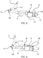
- FIG 3 illustrates the linkage system of the recline mechanism in the closed and upright position.
- front pivot link 9 attaches to carrier link 12 via connection point C19.
- Rear pivot link (15) is connected to carrier link (12) via connection point C17.
- Linear actuator 30 is attached to front motor drive tube (11a) at one end via connection point C24 and at the other end the linear actuator (30) is attached to a second motor drive tube (11b) via connection point C26 (also shown in figure 17 ).
- Front lever (Fulcrum) 20 is a pivotal connection connecting front pivot link 9 to carrier link 12 and rear lever (Fulcrum) 22 is a pivotal connection point between rear pivot link 15 and carrier link 12, as described in Table 1.
- Figure 4 illustrates the same recline mechanism of Figure 3 but in an open or full recline position.
- the recline mechanism includes a floating end actuator 30 as shown in Figures 3, 4 , 6 and 17 .
- Having a floating end as opposed to a fixed end actuator/motor as in prior art mechanisms, has a major advantage in the way it compensates for poor starting or ending angles.
- a floating actuator 30, according to the current invention applies forces in two locations on the moving recline assembly/mechanism thereby decreasing chances of failure.
- Such a floating design as illustrated in Figure 6 , allows actuator 30 to more efficiently articulate the seating assembly or chair by avoiding losses due to the angular position of the driving forces. This way, actuator 30 has a mechanical advantage and is not subject to loads due to poor leverage.
- Figure 5 illustrates prior art design encompassing a fixed end actuator.
- connection points (C24 and C26) Starting from the closed position as in Fig. 1 , the linear actuator 30 would be in the fully extended position which pushes the connection points (C24 and C26) to their furthest distance apart. Activation of the linear actuator 30 shortens the effective distance between the connection points (C24 and C26) which in turn controls the rotation of the front pivot link 9 which pulls the front section of seat rail bracket 10 forward. Concurrently, the position of connection points (C24 and C26) controls the rotation of the rear pivot link 15. Rear pivot link 15, rear pivot upper lift link 13, and rear pivot upper lift control link 14 rotate to a vertically shorter height and in turn pull the rear of the seat rail bracket 10 forward and down toward the full recline position.
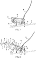
- Figures 7 and 8 illustrate the different components of the recline mechanism of the current invention and its linkage system when the seating assembly/chair is in a closed or in an open/fully reclined configuration.
- the seating assembly may be mounted on a sloped floor or on a flat floor by adjustable legs or by bolts, clamp-type linkage supports or simple threaded legs.
- the components include, in an operational connection, as shown in Figures 7 and 8 , a back frame assembly 50, attached to a seat frame assembly 55, and an optional Ottoman assembly 300.
- the seating member assembly 55 and the back member assembly 50 may be rigidly attached to each other. The use of further linkage to allow the back member to articulate in relation to the seating member is also contemplated.
- Seat frame assembly 55 is rigidly attached to a pair of seat rail brackets 10 one on the left side of the seat and one on the right.
- Front adjustable leg 70 and rear adjustable leg 75 are attached to fixed base 28 which is rigidly attached to carrier link 12
- Adjustable leg 70 and adjustable leg 75 are secured to sloped floor 77.
- Several types of adjustable legs can be used in connection with the linkage mechanism of the current disclosure including bolt on, clamp type, linkage supports and simple threaded legs.
- the seating assembly 200 may further include a foot rest or a main Ottoman assembly 300, as shown in figures 7-9 .
- Ottoman assembly 300 includes in functional operation, main ottoman board 60, flipper ottoman board 65, front adjustable leg 70 and back adjustable legs 77, footrest bracket 1, ottoman link numbers 2, 3, 6, 7, flipper ottoman link 4, flipper ottoman control link 5, ottoman drive link 8.
- Ottoman board 60 attached on both sides to footrest bracket (1) is operatively connected to the seat rail bracket (10) (shown in Figures 1, 2 , 7 and 8 ).
- Flipper Ottoman board 65 is attached to Flipper Ottoman Link 4.
- Ottoman assembly 300 is attached to Ottoman assembly 300 by Ottoman link three and Ottoman link four, (reference numbers 6 and 7 respectively) which are attached to Ottoman links one and Ottoman link two (reference numbers 2 and 3) by foot rest bracket 1 and flipper Ottoman link 4 respectively.
- the Ottoman assembly/foot rest is configured to optionally extend outwards and upwards from the seat or fold under the seat member according to a user preference.
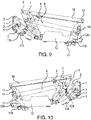
- FIG. 9-17 illustrate the different components of the recline mechanism of the current invention and its linkage system in various configurations.
- the recline mechanism shown in Figure 9 includes front pivot link 9, seat rail bracket 10, motor drive tube assembly 11, carrier link (or fixed base link) 12, rear pivot upper lift link 13, rear pivot upper lift control link 14 and rear pivot link 15.
- Seat rail bracket 10 is attached to rear pivot upper lift link 13 which controls the motion of the rear of the seat.
- Rear pivot upper lift link 13 is attached at the lower end to the upper end of rear pivot link 15, and the latter is connected at its other end to carrier link 12.
- the rear pivot upper lift control link 14 is connected to rear pivot upper lift link 13 and at the lower end to carrier link 12. This contrasts with many existing known mechanisms which are metal-to-the-floor type with a traditional linear actuator drive.
- the seating assembly of the current invention also includes a motor drive tube 11 comprising a floating end motor/actuator 30 that is attached to moving linkage at both ends so as to make full use of the motor stroke and compensate for changing angular forces. Beginning with the linear actuator 30, the two ends of the linear actuator are connected to the motor drive tubes J1A and 11B, as shown in Figure 17 , by pivotal connection C24 and C26.
- Front motor drive tube 11A is rigidly attached to the lower end of front pivot link 9 and rear motor drive tube 11B is rigidly attached to rear pivot link 15.
- This linear actuator connection to front and rear pivot links via motor drives 11A and 11 B is the controlling or driving force that transitions the linkage system between the closed and recline positions.
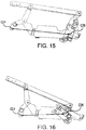
- FIG. 15 is an illustration depicting motor front actuator attachment point C24 and rear actuator attachment point C26.
- Linear actuator 30 forces the two points apart leading to the rotation of front pivot link 9 to an upright position and to the rotation of rear pivot link arrangement (rear pivot upper lift link 13, rear pivot upper lift control link 14 and rear pivot link 15) into upright position
- the rear pivot link arrangement is integral to the compactness of the mechanism. The use of a collapsing linkage in the rear allows for the use of this mechanism on a sloped floor.
- Figure 16 is an illustration also depicting motor attachment points C24 and C26 and the result of the motor forcing C24 and C26 towards each other leading to the rotation of front pivot link 9 forward and pulling the rear pivot link arrangement (rear pivot upper lift link 13, rear pivot upper lift control link 14 and rear pivot link 15) into the collapsed or recline position/configuration.
- Figures 15 and 16 illustrate how the linear actuator pushes and pulls on rear pivot link 15 at point C26 and concurrently front pivot link (9) at point C24, thereby activating all the linkage that is necessary to allow the seating assembly to transition between the closed and open positions.
- Figure 17 shows an isometric view of seating assembly 200 and its recline mechanism 100 having a right side and a left side that are connected laterally by two motor drive tubes (11A and 11B) which act to synchronize both the right and left mechanism side assemblies and activate the side assembly linkage. Both right and left sides have similar links and connections as necessitated to have a symmetrically and operationally functional mechanism as would be well understood by a person of skill in the art.
- Motor drive tubes (11A and 11 B) are rigidly attached to front pivot link 9 and rear pivot link 15.
- Linear actuator 30 is attached to motor drive tubes along a center line running in the assembly from front to back by connection points C24 and C26.
- Typical prior art utilizes only one moving point to drive the mechanism through its motion. The other end of the motor/actuator is connected to a non-moving portion of the mechanism.
Landscapes
- Engineering & Computer Science (AREA)
- Health & Medical Sciences (AREA)
- General Health & Medical Sciences (AREA)
- Dentistry (AREA)
- Mechanical Engineering (AREA)
- Transportation (AREA)
- Aviation & Aerospace Engineering (AREA)
- Chairs For Special Purposes, Such As Reclining Chairs (AREA)
- Seats For Vehicles (AREA)
- Architecture (AREA)
- Multimedia (AREA)
- Civil Engineering (AREA)
- Structural Engineering (AREA)
Applications Claiming Priority (5)
| Application Number | Priority Date | Filing Date | Title |
|---|---|---|---|
| US201562161876P | 2015-05-14 | 2015-05-14 | |
| US201562162558P | 2015-05-15 | 2015-05-15 | |
| US201562162607P | 2015-05-15 | 2015-05-15 | |
| EP16793673.1A EP3282897A4 (de) | 2015-05-14 | 2016-05-14 | Motorbetriebener zurücklehnmechanismus für einen theatersitz auf geneigtem boden |
| PCT/US2016/032585 WO2016183543A1 (en) | 2015-05-14 | 2016-05-14 | Motor driven sloped floor recline mechanism for a theater seat |
Related Parent Applications (1)
| Application Number | Title | Priority Date | Filing Date |
|---|---|---|---|
| EP16793673.1A Division EP3282897A4 (de) | 2015-05-14 | 2016-05-14 | Motorbetriebener zurücklehnmechanismus für einen theatersitz auf geneigtem boden |
Publications (1)
| Publication Number | Publication Date |
|---|---|
| EP3603453A1 true EP3603453A1 (de) | 2020-02-05 |
Family
ID=57248667
Family Applications (2)
| Application Number | Title | Priority Date | Filing Date |
|---|---|---|---|
| EP19198111.7A Withdrawn EP3603453A1 (de) | 2015-05-14 | 2016-05-14 | Motorbetriebener zurücklehnmechanismus für einen theatersitz auf geneigtem boden |
| EP16793673.1A Withdrawn EP3282897A4 (de) | 2015-05-14 | 2016-05-14 | Motorbetriebener zurücklehnmechanismus für einen theatersitz auf geneigtem boden |
Family Applications After (1)
| Application Number | Title | Priority Date | Filing Date |
|---|---|---|---|
| EP16793673.1A Withdrawn EP3282897A4 (de) | 2015-05-14 | 2016-05-14 | Motorbetriebener zurücklehnmechanismus für einen theatersitz auf geneigtem boden |
Country Status (11)
| Country | Link |
|---|---|
| US (2) | US10118508B2 (de) |
| EP (2) | EP3603453A1 (de) |
| JP (1) | JP2018514291A (de) |
| CN (1) | CN107847052A (de) |
| AU (1) | AU2016262581A1 (de) |
| BR (1) | BR112017024500A2 (de) |
| CA (1) | CA2985651A1 (de) |
| CO (1) | CO2017011149A2 (de) |
| HK (1) | HK1252097A1 (de) |
| MX (1) | MX2017014122A (de) |
| WO (1) | WO2016183543A1 (de) |
Families Citing this family (13)
| Publication number | Priority date | Publication date | Assignee | Title |
|---|---|---|---|---|
| CA2985651A1 (en) | 2015-05-14 | 2016-11-17 | VIP Cinema LLC | Motor driven sloped floor recline mechanism for a theater seat |
| CN107920663A (zh) | 2015-05-14 | 2018-04-17 | Vip影院有限责任公司 | 用于剧院的双运动斜地面倾斜机构 |
| EP3143902B2 (de) * | 2015-09-15 | 2023-04-26 | Ciar S.P.A. | Wandbündige rücklehne |
| CN110290729B (zh) * | 2016-12-12 | 2023-09-12 | 厄特拉-梅克公司 | 具有分体式椅座的助力躺倚式升降椅 |
| WO2018140110A1 (en) | 2017-01-26 | 2018-08-02 | Ultra-Mek, Inc. | Reclining high-leg seating unit |
| EP3635277A1 (de) * | 2017-06-07 | 2020-04-15 | VIP Cinema LLC | Linearaktuator mit externen variablen begrenzungsschaltern |
| WO2020132652A1 (en) * | 2018-12-21 | 2020-06-25 | VIP Cinema LLC | Mechanism for actuating motion furniture |
| WO2021066804A1 (en) * | 2019-09-30 | 2021-04-08 | Safran Seats Usa Llc | Zero intrusion kinematic and recline mechanism for commercial aircraft seats |
| KR102440701B1 (ko) * | 2020-08-12 | 2022-09-05 | 현대자동차주식회사 | 자동차용 파워 레그레스트 |
| US11178970B1 (en) * | 2020-09-29 | 2021-11-23 | L&P Property Management Company | High-leg hidden ottoman recliner seating mechanism |
| DE102021122430A1 (de) * | 2021-08-31 | 2023-03-02 | Ferdinand Lusch Gmbh | Schwenkbeschlag eines sitzmöbels zum verstellen eines fussteils und sitzmöbel mit verstellbarem fussteil |
| KR102625677B1 (ko) * | 2022-01-11 | 2024-01-15 | 대원강업주식회사 | 어린이용 부스터 시트 |
| KR102507132B1 (ko) * | 2022-06-17 | 2023-03-07 | 건영테크(주) | 암레스트 어셈블리 |
Citations (2)
| Publication number | Priority date | Publication date | Assignee | Title |
|---|---|---|---|---|
| US20150054315A1 (en) * | 2013-08-21 | 2015-02-26 | L&P Property Management Company | Reclining and ottoman-extending chair mechanism |
| US20150076883A1 (en) * | 2013-09-19 | 2015-03-19 | La-Z-Boy Incorporated | Furniture member power mechanism with zero gravity and rear tilt positions |
Family Cites Families (31)
| Publication number | Priority date | Publication date | Assignee | Title |
|---|---|---|---|---|
| GB442438A (en) | 1934-07-31 | 1936-01-31 | Carl Gustav Thorbjorn Salenius | Improvements in silencers for internal combustion engines |
| FR1322483A (fr) * | 1962-04-20 | 1963-03-29 | Perfectionnements apportés aux mécanismes destinés à fournir les positions successives d'un fauteuil inclinable du type à mouvements multiples | |
| US3558185A (en) * | 1968-09-10 | 1971-01-26 | Gen Steel Products Inc | Reclining chair mechanism |
| US4226473A (en) * | 1978-03-13 | 1980-10-07 | Pontiac Furniture Industries, Inc. | Reclining chair |
| US4641808A (en) | 1985-02-22 | 1987-02-10 | Flower Wallace C | Dynamic vibration attenuator utilizing inertial fluid |
| US5288128A (en) | 1992-04-24 | 1994-02-22 | Hussey Seating Company | Reclining theater seating |
| US5393120A (en) | 1992-10-13 | 1995-02-28 | Krueger International, Inc. | Auditorium seating system |
| AU3569997A (en) * | 1996-06-14 | 1998-01-07 | L&P Property Management Company | Three-way reclining furniture item |
| US20010035668A1 (en) * | 1999-05-06 | 2001-11-01 | Edward J. Gaffney | Power actuated reclining chair with wall-hugger function |
| US6582020B1 (en) | 2000-08-28 | 2003-06-24 | Greystone International, Inc. | Theater seat assembly |
| DE20106560U1 (de) | 2001-04-14 | 2002-08-29 | Dewert Antriebs Systemtech | Sitz-Liegesesselbeschlag motorisch verstellbar |
| US6742841B1 (en) | 2003-05-23 | 2004-06-01 | Johnson Controls Technology Company | Vehicle seat with auto-fold leg |
| DE202005000878U1 (de) * | 2005-01-20 | 2005-03-24 | Lusch Gmbh & Co Kg Ferd | Sitzmöbel |
| US7568764B2 (en) | 2007-01-08 | 2009-08-04 | Ford Global Technologies, Llc | Reclining rear seat for vehicle having four-bar link |
| JP2008173332A (ja) | 2007-01-19 | 2008-07-31 | Delta Tooling Co Ltd | 座席構造 |
| NO326574B1 (no) | 2007-03-13 | 2009-01-12 | Sapdesign As | Anordning ved stol med justerbar vinkel mellom stolens sete og rygg |
| TWM378690U (en) * | 2009-12-01 | 2010-04-21 | Chi Bo Industry Co Ltd | Machine capable of adjusting gap between seat pad and back cushion |
| US10070724B2 (en) | 2009-12-17 | 2018-09-11 | Matthew Jacobs | Rocker style chairs, modular components for use within rocker style chairs and parts for use within the modular components |
| US8419122B2 (en) * | 2010-01-25 | 2013-04-16 | L & P Property Management Company | Zero-wall clearance linkage mechanism for a high-leg seating unit |
| US8534759B2 (en) | 2010-09-24 | 2013-09-17 | Be Aerospace, Inc. | Passenger seat armrest recline mechanism |
| US8517463B2 (en) * | 2010-11-09 | 2013-08-27 | Ultra-Mek, Inc. | Gliding-reclining layflat seating unit with power actuator and manual and automatic locking linkages |
| US9603453B2 (en) * | 2010-12-29 | 2017-03-28 | Ultra-Mek, Inc. | Reclining chair with tilting action to provide heart-rest position |
| CN202234151U (zh) * | 2011-08-30 | 2012-05-30 | 李建华 | 电动铰接机构 |
| US20170021930A1 (en) | 2014-04-02 | 2017-01-26 | B/E Aerospace, Inc. | Cradle recline mechanism for aircraft passenger seat |
| US9603452B2 (en) * | 2014-10-14 | 2017-03-28 | Ultra-Mek, Inc. | Gliding-reclining seating unit with power actuators |
| DE102015102007B3 (de) | 2015-02-12 | 2016-07-28 | Wilkhahn Wilkening + Hahne Gmbh + Co. | Sitzmöbel |
| CN107529891B (zh) | 2015-04-04 | 2022-03-22 | 弗里德里克·杰克布斯 | 用于公共场所的电动椅、用于电动椅的组件以及用在用于电动椅的组件中的部件 |
| CN107920663A (zh) | 2015-05-14 | 2018-04-17 | Vip影院有限责任公司 | 用于剧院的双运动斜地面倾斜机构 |
| CA2985651A1 (en) | 2015-05-14 | 2016-11-17 | VIP Cinema LLC | Motor driven sloped floor recline mechanism for a theater seat |
| US10085570B2 (en) | 2016-05-13 | 2018-10-02 | Srigiri Shankar Bellam | Posture detection and correction cushion |
| US10973333B2 (en) | 2016-09-30 | 2021-04-13 | Adient Luxembourg Holding S.Á R.L. | Stadium seat having a split back recliner and a vehicle including a stadium seat having a split back recliner |
-
2016
- 2016-05-14 CA CA2985651A patent/CA2985651A1/en not_active Abandoned
- 2016-05-14 EP EP19198111.7A patent/EP3603453A1/de not_active Withdrawn
- 2016-05-14 JP JP2017555802A patent/JP2018514291A/ja not_active Ceased
- 2016-05-14 AU AU2016262581A patent/AU2016262581A1/en not_active Abandoned
- 2016-05-14 BR BR112017024500A patent/BR112017024500A2/pt not_active Application Discontinuation
- 2016-05-14 EP EP16793673.1A patent/EP3282897A4/de not_active Withdrawn
- 2016-05-14 WO PCT/US2016/032585 patent/WO2016183543A1/en active Application Filing
- 2016-05-14 CN CN201680027623.5A patent/CN107847052A/zh active Pending
- 2016-05-14 US US15/155,004 patent/US10118508B2/en active Active
- 2016-05-14 MX MX2017014122A patent/MX2017014122A/es unknown
-
2017
- 2017-10-30 CO CONC2017/0011149A patent/CO2017011149A2/es unknown
-
2018
- 2018-09-05 HK HK18111407.4A patent/HK1252097A1/zh unknown
- 2018-10-24 US US16/169,904 patent/US10507742B2/en active Active
Patent Citations (2)
| Publication number | Priority date | Publication date | Assignee | Title |
|---|---|---|---|---|
| US20150054315A1 (en) * | 2013-08-21 | 2015-02-26 | L&P Property Management Company | Reclining and ottoman-extending chair mechanism |
| US20150076883A1 (en) * | 2013-09-19 | 2015-03-19 | La-Z-Boy Incorporated | Furniture member power mechanism with zero gravity and rear tilt positions |
Also Published As
| Publication number | Publication date |
|---|---|
| CA2985651A1 (en) | 2016-11-17 |
| EP3282897A1 (de) | 2018-02-21 |
| JP2018514291A (ja) | 2018-06-07 |
| US20190061569A1 (en) | 2019-02-28 |
| US10507742B2 (en) | 2019-12-17 |
| HK1252097A1 (zh) | 2019-05-17 |
| US20160332541A1 (en) | 2016-11-17 |
| US10118508B2 (en) | 2018-11-06 |
| WO2016183543A1 (en) | 2016-11-17 |
| EP3282897A4 (de) | 2018-11-07 |
| CN107847052A (zh) | 2018-03-27 |
| CO2017011149A2 (es) | 2018-03-20 |
| MX2017014122A (es) | 2018-07-06 |
| AU2016262581A1 (en) | 2017-11-09 |
| BR112017024500A2 (pt) | 2018-09-11 |
Similar Documents
| Publication | Publication Date | Title |
|---|---|---|
| US10507742B2 (en) | Motor driven sloped floor recline mechanism for a theater seat | |
| US11793311B2 (en) | Dual motion sloped floor recline mechanism for a theater seat | |
| EP3171734B1 (de) | Verbindungsmechanismus mit wandfreiem abstand mit antrieb für elektrisch verstellbaren sitz | |
| EP2878229B1 (de) | Verbindungsmechanismen für angetriebenen Schaukel- und Lehnstuhl | |
| US8398165B2 (en) | Powered rocker recliner linkage mechanism | |
| US9603452B2 (en) | Gliding-reclining seating unit with power actuators | |
| CN101912207B (zh) | 避开壁的可变换凳榻 | |
| US9050231B2 (en) | Seat-lift assembly | |
| JP2017100721A (ja) | 移動する背もたれリンケージ枢動軸を備える航空機用座席 | |
| CN101485522A (zh) | 用于高腿座椅单元的零墙壁间隙的连杆机构 | |
| MX2012008659A (es) | Mecanismo articulado de espacio cero de pared para unidad de asiento de extremidad alta. | |
| WO2015148484A1 (en) | Zero-wall clearance linkage mechanism including a single drive link | |
| MX2012009329A (es) | Mecanismo de eslabon de cero holgura de pared para un reciclador elevador. | |
| CN102669974A (zh) | 用于高腿座椅单元的连杆机构 | |
| US10258159B2 (en) | Tilt mechanism for a seating furniture and seating furniture including the same | |
| US11832727B2 (en) | Reclining seating unit with wall-proximity capability and extendable headrest |
Legal Events
| Date | Code | Title | Description |
|---|---|---|---|
| PUAI | Public reference made under article 153(3) epc to a published international application that has entered the european phase |
Free format text: ORIGINAL CODE: 0009012 |
|
| STAA | Information on the status of an ep patent application or granted ep patent |
Free format text: STATUS: THE APPLICATION HAS BEEN PUBLISHED |
|
| AC | Divisional application: reference to earlier application |
Ref document number: 3282897 Country of ref document: EP Kind code of ref document: P |
|
| AK | Designated contracting states |
Kind code of ref document: A1 Designated state(s): AL AT BE BG CH CY CZ DE DK EE ES FI FR GB GR HR HU IE IS IT LI LT LU LV MC MK MT NL NO PL PT RO RS SE SI SK SM TR |
|
| STAA | Information on the status of an ep patent application or granted ep patent |
Free format text: STATUS: REQUEST FOR EXAMINATION WAS MADE |
|
| 17P | Request for examination filed |
Effective date: 20200805 |
|
| RBV | Designated contracting states (corrected) |
Designated state(s): AL AT BE BG CH CY CZ DE DK EE ES FI FR GB GR HR HU IE IS IT LI LT LU LV MC MK MT NL NO PL PT RO RS SE SI SK SM TR |
|
| STAA | Information on the status of an ep patent application or granted ep patent |
Free format text: STATUS: THE APPLICATION IS DEEMED TO BE WITHDRAWN |
|
| 18D | Application deemed to be withdrawn |
Effective date: 20200806 |