EP3603232B1 - Dispositif terminal et dispositif relais et procédés - Google Patents
Dispositif terminal et dispositif relais et procédés Download PDFInfo
- Publication number
- EP3603232B1 EP3603232B1 EP18706772.3A EP18706772A EP3603232B1 EP 3603232 B1 EP3603232 B1 EP 3603232B1 EP 18706772 A EP18706772 A EP 18706772A EP 3603232 B1 EP3603232 B1 EP 3603232B1
- Authority
- EP
- European Patent Office
- Prior art keywords
- transmission power
- relay device
- relay
- terminal device
- base station
- Prior art date
- Legal status (The legal status is an assumption and is not a legal conclusion. Google has not performed a legal analysis and makes no representation as to the accuracy of the status listed.)
- Active
Links
Images


Classifications
-
- H—ELECTRICITY
- H04—ELECTRIC COMMUNICATION TECHNIQUE
- H04W—WIRELESS COMMUNICATION NETWORKS
- H04W52/00—Power management, e.g. Transmission Power Control [TPC] or power classes
- H04W52/04—Transmission power control [TPC]
- H04W52/38—TPC being performed in particular situations
- H04W52/46—TPC being performed in particular situations in multi-hop networks, e.g. wireless relay networks
-
- H—ELECTRICITY
- H04—ELECTRIC COMMUNICATION TECHNIQUE
- H04W—WIRELESS COMMUNICATION NETWORKS
- H04W52/00—Power management, e.g. Transmission Power Control [TPC] or power classes
- H04W52/04—Transmission power control [TPC]
- H04W52/06—TPC algorithms
- H04W52/14—Separate analysis of uplink or downlink
- H04W52/146—Uplink power control
-
- H—ELECTRICITY
- H04—ELECTRIC COMMUNICATION TECHNIQUE
- H04W—WIRELESS COMMUNICATION NETWORKS
- H04W52/00—Power management, e.g. Transmission Power Control [TPC] or power classes
- H04W52/04—Transmission power control [TPC]
- H04W52/18—TPC being performed according to specific parameters
- H04W52/24—TPC being performed according to specific parameters using SIR [Signal to Interference Ratio] or other wireless path parameters
- H04W52/242—TPC being performed according to specific parameters using SIR [Signal to Interference Ratio] or other wireless path parameters taking into account path loss
-
- H—ELECTRICITY
- H04—ELECTRIC COMMUNICATION TECHNIQUE
- H04W—WIRELESS COMMUNICATION NETWORKS
- H04W52/00—Power management, e.g. Transmission Power Control [TPC] or power classes
- H04W52/04—Transmission power control [TPC]
- H04W52/18—TPC being performed according to specific parameters
- H04W52/24—TPC being performed according to specific parameters using SIR [Signal to Interference Ratio] or other wireless path parameters
- H04W52/243—TPC being performed according to specific parameters using SIR [Signal to Interference Ratio] or other wireless path parameters taking into account interferences
-
- H—ELECTRICITY
- H04—ELECTRIC COMMUNICATION TECHNIQUE
- H04W—WIRELESS COMMUNICATION NETWORKS
- H04W52/00—Power management, e.g. Transmission Power Control [TPC] or power classes
- H04W52/04—Transmission power control [TPC]
- H04W52/18—TPC being performed according to specific parameters
- H04W52/28—TPC being performed according to specific parameters using user profile, e.g. mobile speed, priority or network state, e.g. standby, idle or non-transmission
- H04W52/283—Power depending on the position of the mobile
-
- H—ELECTRICITY
- H04—ELECTRIC COMMUNICATION TECHNIQUE
- H04W—WIRELESS COMMUNICATION NETWORKS
- H04W52/00—Power management, e.g. Transmission Power Control [TPC] or power classes
- H04W52/04—Transmission power control [TPC]
- H04W52/38—TPC being performed in particular situations
- H04W52/383—TPC being performed in particular situations power control in peer-to-peer links
-
- H—ELECTRICITY
- H04—ELECTRIC COMMUNICATION TECHNIQUE
- H04W—WIRELESS COMMUNICATION NETWORKS
- H04W88/00—Devices specially adapted for wireless communication networks, e.g. terminals, base stations or access point devices
- H04W88/02—Terminal devices
- H04W88/04—Terminal devices adapted for relaying to or from another terminal or user
-
- H—ELECTRICITY
- H04—ELECTRIC COMMUNICATION TECHNIQUE
- H04W—WIRELESS COMMUNICATION NETWORKS
- H04W52/00—Power management, e.g. Transmission Power Control [TPC] or power classes
- H04W52/04—Transmission power control [TPC]
- H04W52/06—TPC algorithms
- H04W52/10—Open loop power control
-
- H—ELECTRICITY
- H04—ELECTRIC COMMUNICATION TECHNIQUE
- H04W—WIRELESS COMMUNICATION NETWORKS
- H04W52/00—Power management, e.g. Transmission Power Control [TPC] or power classes
- H04W52/04—Transmission power control [TPC]
- H04W52/18—TPC being performed according to specific parameters
- H04W52/24—TPC being performed according to specific parameters using SIR [Signal to Interference Ratio] or other wireless path parameters
- H04W52/241—TPC being performed according to specific parameters using SIR [Signal to Interference Ratio] or other wireless path parameters taking into account channel quality metrics, e.g. SIR, SNR, CIR or Eb/lo
-
- H—ELECTRICITY
- H04—ELECTRIC COMMUNICATION TECHNIQUE
- H04W—WIRELESS COMMUNICATION NETWORKS
- H04W52/00—Power management, e.g. Transmission Power Control [TPC] or power classes
- H04W52/04—Transmission power control [TPC]
- H04W52/18—TPC being performed according to specific parameters
- H04W52/24—TPC being performed according to specific parameters using SIR [Signal to Interference Ratio] or other wireless path parameters
- H04W52/245—TPC being performed according to specific parameters using SIR [Signal to Interference Ratio] or other wireless path parameters taking into account received signal strength
-
- H—ELECTRICITY
- H04—ELECTRIC COMMUNICATION TECHNIQUE
- H04W—WIRELESS COMMUNICATION NETWORKS
- H04W52/00—Power management, e.g. Transmission Power Control [TPC] or power classes
- H04W52/04—Transmission power control [TPC]
- H04W52/30—Transmission power control [TPC] using constraints in the total amount of available transmission power
- H04W52/36—Transmission power control [TPC] using constraints in the total amount of available transmission power with a discrete range or set of values, e.g. step size, ramping or offsets
- H04W52/367—Power values between minimum and maximum limits, e.g. dynamic range
Definitions
- the present disclosure relates to relay devices which are configured to relay signals between terminal devices and a base station in a mobile communications network.
- the present application is related to European patent application 17164263.0 the contents of which may be of interest to the skilled reader.
- Third and fourth generation wireless communications systems such as those based on the third generation partnership project (3GPP) defined UMTS and Long Term Evolution (LTE) architecture are able to support sophisticated services such as instant messaging, video calls as well as high speed internet access.
- 3GPP third generation partnership project
- LTE Long Term Evolution
- a user is able to enjoy high data rate applications such as mobile video streaming and mobile video conferencing that would previously only have been available via a fixed line data connection.
- the demand to deploy third and fourth generation networks is therefore strong and the coverage area of these networks, i.e. geographic locations where access to the networks is possible, is expected to increase rapidly.
- fourth generation networks can support communications at high data rate and low latencies from devices such as smart phones and tablet computers
- future wireless communications networks will need to support communications to and from a much wider range of devices, including reduced complexity devices, machine type communication (MTC) devices, wearable devices, devices which require little or no mobility, high resolution video displays and virtual reality headsets.
- MTC machine type communication
- D2D device-to-device
- loT narrow band
- LTE or 4G wireless access interface and wireless infrastructure A current technical area of interest to those working in the field of wireless and mobile communications is known as "The Internet of Things" or loT for short.
- the 3GPP has proposed to develop technologies for supporting narrow band (NB)-loT using an LTE or 4G wireless access interface and wireless infrastructure.
- NB-loT devices are expected to be low complexity and inexpensive devices requiring infrequent communication of relatively low bandwidth data. It is also expected that there will be an extremely large number of loT devices which would need to be supported in a cell of the wireless communications network.
- NB-loT devices are likely to be deployed indoors and /or in remote locations making radio communications challenging.
- RATs new Radio Access Technologies
- 5G 5 th generation
- NR New Radio
- Figure 1 provides a schematic diagram illustrating some basic functionality of a mobile telecommunications network / system operating in accordance with LTE principles and which may be adapted to implement embodiments of the disclosure as described further below.
- Various elements of Figure 1 and their respective modes of operation are well-known and defined in the relevant standards administered by the 3GPP (RTM) body, and also described in many books on the subject, for example, Holma H. and Toskala A [1]. It will be appreciated that operational aspects of the telecommunications network which are not specifically described below may be implemented in accordance with any known techniques, for example according to the relevant standards.
- the network 100 includes a plurality of base stations 101 connected to a core network 102.
- Each base station provides a coverage area 103 (i.e. a cell) within which data can be communicated to and from communications devices 104.
- Data is transmitted from base stations 101 to communications devices 104 within their respective coverage areas 103 via a radio downlink.
- Data is transmitted from communications devices 104 to the base stations 101 via a radio uplink.
- the uplink and downlink communications are made using radio resources that are licenced for exclusive use by the operator of the network 100.
- the core network 102 routes data to and from the communications devices 104 via the respective base stations 101 and provides functions such as authentication, mobility management, charging and so on.
- Communications devices may also be referred to as mobile stations, user equipment (UE), user device, mobile radio, and so forth.
- Base stations may also be referred to as transceiver stations / infrastructure equipment / NodeBs / eNodeBs (eNB for short) / gNodeBs, and so
- Wireless communications systems such as those arranged in accordance with the 3GPP defined Long Term Evolution (LTE) architecture use an orthogonal frequency division modulation (OFDM) based interface for the radio downlink (so-called OFDMA) and a single carrier frequency division multiple access scheme (SC-FDMA) on the radio uplink.
- OFDM orthogonal frequency division modulation
- SC-FDMA single carrier frequency division multiple access scheme
- Mobile communications networks may further include relay nodes, to try to extend a radio coverage area provided by the network to reach communications devices which would otherwise be out of range of the mobile communications network or to improve the ratio of successful transmissions between a terminal and a base station.
- Relay nodes further allow power consumption at the terminal to be reduced, as the range of transmission for that terminal will be reduced.
- Other benefits of using devices as relay nodes include better network resource utilisation, because a short device to device communication range means that resources can be re-used in different regions of a cell, a shorter range potentially means less retransmissions or repetitions of data, and because a shorter range means less interference due to a lower transmit power.
- Communication devices configured to act as relay nodes may also reduce signalling overhead, because for example mobility related signalling procedures may be performed by the relay node on behalf of remote UEs connected to the relay, rather than being performed by each individual device.
- the relay node functionality allows a remote device to be identifiable and addressable by the mobile network operator, allows operator control of quality of service, and provides end-to-end security, providing advantages over traditional tethering which is already possible for example by use of Bluetooth.
- the remote UE that is the terminal that connects to the network through the relay device can also sometimes be referred to as UE, terminal, terminal devices, mobile device, D2D device, etc. and may be of any type suitable to use a relay device.
- the relay device may be any suitable type of devices, such as a terminal or UE operating at least in part as a relay node, a dedicated relay node, infrastructure equipment (e.g. a base station) operating at least in part as a relay node and may be referred to as a relay device, relay, relay node, relay UE, etc. as appropriate.
- FIG. 2 illustrates an example network comprising an eNodeB 201 with a coverage area 202.
- Two UEs 203 and 204 may communicate with one another using device-to-device (D2D) communications.
- D2D device-to-device
- each of the UEs 203 and 204 communicate with a relay node 205, which then relays signals to and from the eNodeB 201.
- both UEs 203 and 204 are inside the coverage area 202 of the eNodeB 201, so signals are not necessarily being relayed for coverage purposes.
- the UEs 203 and 204 may be low power devices, and so communicating with the relay node 205 consumes less power (as communications are over a shorter range) than communicating directly with the eNodeB 201 would do.
- a relay node can generally be defined as a wireless radio access point for relaying transmission and which thus does not implement all of the functionalities of a base station. It is in general not directly connected to the core network but uses wireless access (inband or outband) for backhaul link to connect with a base station.
- wireless access inband or outband
- Relay technologies (such as a communication device configured to act as a relay) are known generally to provide an arrangement for receiving signals from a base station and for retransmitting the received signals to a UE in a mobile communications network, or to receive signals transmitted from a UE for re-transmission to a base station of a mobile communications network.
- the backhaul link may also be provided over a wired connection.
- Relay technologies are known generally to provide an arrangement for receiving signals from a base station and for retransmitting the received signals to a UE in a mobile communications network, or to receive signals transmitted from a UE for re-transmission to a base station of a mobile communications network.
- NB-loT Narrowband Internet of Things
- 3GPP a project relating to improvements to LTE wireless access interfaces to provide for a Narrowband Internet of Things (NB-loT) was agreed [2].
- This project is aimed at improved indoor coverage, support for massive number of low throughput devices, low delay sensitivity, ultra-low device cost, low device power consumption and (optimised) network architecture.
- An example of such a device is a smart meter. It has been proposed that an NB-loT communications system supports a bandwidth of only 180 kHz and can have three operational modes:
- LC-MTC Low Complexity Machine Type Communication
- UEs LC-MTC terminal devices
- LTE features which are currently being specified in 3GPP.
- the main features of LC-MTC UE are low complexity (and therefore low cost), coverage enhancement and reduced power consumption.
- Wearable devices are examples of devices which may make use of NB-loT or LC-MTC communications systems.
- 3GPP Rel. 14 a study item into further enhancements to LTE D2D communications, network relays for loT and wearable devices has been approved [3], including the enhancement of D2D to be more suitable for lower cost/complexity (e.g. wearable) devices.
- the first phase of the study will evaluate scenarios and requirements with the intention of refining and updating current objectives.
- relay technologies will form part of the future work on new radio access technology (RAT) for fifth generation (5G) wireless communication systems. It is anticipated that enhancements made to LTE D2D will also be applicable to these 5G systems.
- RAT new radio access technology
- a remote device e.g. a wearable device such as a smart watch
- uplink transmissions can be performed at a much shorter range to the relay device, rather than to the eNodeB.
- a remote device e.g. a wearable device such as a smart watch
- uplink transmissions can be performed at a much shorter range to the relay device, rather than to the eNodeB.
- One potential realisation of this would be to utilise a narrowband channel similar to eMTC or NB-loT for the relay link. This would be suitable for sending (and also potentially receiving) small amounts of data via the relay.
- Another possibility would be to use Bluetooth or Wi-Fi for the relay link (sidelink).
- Figure 3 illustrates an example scenario in which a remote wearable device 303 may communicate with an eNodeB 301 using a communications device 305 as a relay node.
- the eNodeB 301 has a coverage area 302, which the remote wearable device 303 and communications device 305 are within.
- the remote wearable device 303 is connected by a narrowband link 311 to the communications device 305, and the communications device is connected by a conventional link 312 to the eNodeB 301.
- the remote wearable device 303 may be, for example, a smartwatch, while the communications device 305 may be, for example a smartphone.
- the owner of the smartwatch may also own the smartphone, or alternatively, they may be owned by separate users.
- a limited bandwidth for example 6 PRBs (Physical Resource Blocks) / 1.4 MHz bandwidth sidelink similar to MTC.
- a UE with a limited receiver bandwidth e.g. supporting LTE Cat-M
- LTE Cat-M will also support a limited bandwidth for sidelink, in addition to direct link with the eNB.
- a remote UE 303 e.g. limited bandwidth wearable device
- a relay UE 305 e.g. Cat.1+ smartphone
- the UEs must first perform a selection procedure and establish the PC5 connection.
- the remote UE performs measurements on D2DSS (Device to Device Synchronisation Signal) transmitted by one or more relays, and once the criterion is met (e.g. RSRP (Reference Signal Received Power) or RSRQ (Reference Signal Received Quality) is above a threshold) then a relay may be selected, and a PC5 connection can be established to perform D2D (Device to Device) communication.
- D2DSS Device to Device Synchronisation Signal
- RSRP Reference Signal Received Power
- RSRQ Reference Signal Received Quality
- a radio resource pool is provided to the remote UE 303 to perform reception of various D2D signals.
- D2DSS, D2D discovery, and D2D sidelink data and control radio resource pools are provided. Due to the limited bandwidth of the remote UE 303, an efficient method for performing measurement, sync, discovery and communication is necessary.
- D2D transmissions are configured such that the remote terminal transmits all of its D2D transmissions at full power, that is, using a network configured (via broadcast signalling) maximum and constant power.
- This technical choice is supported by the historical design of D2D for safety and emergency services, and specifically for supporting devices out of network coverage via a relay. While this may be well adapted to safety applications, for other cases, such as commercial or wearables cases, such a use of the full transmission power can have a detrimental effect on the device's battery and on the level of interferences around the device, while providing potentially little or no benefit especially at short range.
- a closed loop power control technique is used to control the transmission power for LTE PUSCH transmissions.
- Such a technique requires frequent feedback from the receiver so that the transmitter can adjust the power of each transmission accordingly. While this approach has some benefit in a more conventional environment, it has limitations that can be more prominent in D2D situations.
- a closed loop control system will involve a high level of resource and control signalling overhead in the reverse link which, when applied to a D2D situation, will also risk unduly draining the remote and relay device's battery.
- an eNodeB can configure power control parameters for D2D UEs.
- the configured transmission power is only for reducing interferences at the eNodeB's receiver. It is generally not an optimal configuration of the transmission power on the sidelink (PC5). In particular, the power might be higher than what may be considered as sufficient to achieve the designed signal to noise/interference ratio (SINR). Namely, only the path loss between a D2D UE and eNodeB can be taken into account and there is no consideration for monitoring the connection between the relay terminal and remote terminal, let alone how to control the transmission power for this link.
- SINR signal to noise/interference ratio
- FIG. 4 is a schematic block diagram of a mobile communications system 400.
- the system comprises a relay device 420, one or more terminal devices 430 operating with a mobile communications network and infrastructure equipment 410 (e.g. base station) forming part of the mobile communications network.
- Each of the relay node 420, terminal devices 430 and infrastructure equipment 410 as shown in Figure 4 comprise a transmitter (or transmitter circuitry) 421, 431, 411, a receiver (or receiver circuitry) 422, 432, 412 and a controller (or controller circuitry) 423, 433, 413 to control the transmitter 421, 431, 411 and receiver 422, 432, 412.
- Each of the 423, 433, 413 may be, for example, a microprocessor, a CPU, or a dedicated chipset, etc.
- the remote communications device/UE 430 may not always include a transmitter 431, for example in scenarios where the remote UE 430 is a low-power wearable device.
- the transmission power of the terminal device 430 for signals transmitted to the relay node 420 can be controlled using an open loop power control technique.
- the remote D2D can adjust its transmission power based on current circumstances but without constant feedback as required in a closed loop arrangement.
- the remote UE receives from the relay node an indication of a maximum transmission power that it can use and the remote UE can then decide which transmission power to actually use, so long as it does not exceed the maximum transmission power.
- the D2D transmitter can adjust its power setting without constant feedback and instructions from the network or relay.
- the maximum transmission power communicated to the terminal can be set based on the D2D (PC5) link quality and/or on the Uu link quality.
- the terminal i.e. the transmitting device whose power is being controlled, can set the actual power of its transmissions based on measurements of the received D2D signal.
- the terminal can carry out an RSRP measurement or RSRP-like measurement on the SideLink Synchronisation Signals (SLSS) received from the relay. Accordingly, the terminal will be able to adjust its transmission power on a regular basis using measurements results while only limited instructions are received for the terminal, namely a maximum transmission power that the terminal can use.
- SLSS SideLink Synchronisation Signals
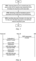
- Figure 5 shows a block diagram illustrating a method of operating a relay node in accordance with an example of the present disclosure.
- the relay node selects a maximum transmission power to be used by the terminal device for communicating with the relay device, wherein the identified maximum transmission power is based on link information relating to one or both of the link between the relay device and the base station and the link between the relay device and the terminal.
- the relay node notifies the communication device of the selected maximum transmission power. Accordingly, the terminal selects an actual transmission power that does not exceed this maximum and transmits signals to the relay device at the actual transmission power.
- the relay node can select the maximum transmission power based on a distance or estimated distance between the relay and base station. For example, for longer distance between the two, the selected maximum transmission power can be the same or higher than a selected maximum transmission power for a shorter distance.
- the distance can be estimated at least in part based on the link information relating to the link between the relay device and the base station.
- the relay can use path loss (the difference between actual transmit power, and received or measured power) information to estimate a distance to the base station.
- a base station can calculate the timing advance (TA) between the relay and the base station based on a uU round trip propagation delay.
- TA timing advance
- the base station can convert the propagation delay to a distance with the speed of electromagnetic wave (light) and from this the distance between the relay and base station can be derived or estimated.
- the distance can be estimated based on a specific measurable distance (e.g. in m, km etc.), a pathloss (dB) or based on a category (e.g. "close”, "medium” or "far” or in a category measured from 0 to N).
- the relay node can select the maximum transmission power based on a distance or estimated distance between the relay and other relays. For example, if there are no other relays communicating near the relay terminal, the relay terminal and the terminal transmitting signals are less likely to cause interference with signals for other relay UEs and can thus use higher power settings. On the other hand, if there are other relays currently communicating near the relay terminal, the relay terminal can use a lower transmission power so as to limit the interference with the signals for the other relay terminals. In some examples, the calculation of the distance or estimated distance can be based on a path loss and/or TA information. To identify the other relays around the relay terminal, a discovery signal or SLSS signal may be used.
- the maximum transmission power for the D2D devices of the relay terminal can be set accordingly.
- the threshold e.g. provided by the base station or preconfigured
- such a further relay terminal can transmit "interference indicator" to the base station and/or other relay terminals that they are suffering from interference from other devices.
- the base station can take appropriate actions to reduce interference such as changing resource pool to make them orthogonal or indicate interference source relay to reduce power or can instruct one or more of the active relay terminals to reduce the maximum transmission power parameter used for their D2D respective terminals.
- a base station may instruct one or more terminal device(s) communicating with an interference source relay to handover to another relay UE stop the operation of the interference source relay in order to help reduce interference in the system.
- a remote terminal using a higher transmission power at the edge of a cell is less likely to cause interference to regular uplink transmissions than when using the same transmission power close to the base station. Accordingly, by setting a maximum transmission power for the terminal based at least in part on an estimated distance between the relay and base station, the power control (taking into account the effect on the interference level) can be further enhanced.
- the relay device can select a maximum transmission power based on at least one of (i) a received power, (ii) a carrier-to-noise and (iii) a signal-to-noise measurement for one of or more of the link between the relay device and the base station, the link between the relay device and the terminal, the link between the relay device and another other relay device, the link between the relay device and a remote device.
- the relay device can select the maximum transmission power based on relay power information transmitted by the base station to the relay device.
- the maximum transmission power can be set by the base station for the relay node based on the link between the base station and the relay node (and on the relay node and the terminal device if one or both devices have notified the base station accordingly) and based on any other information that the base station has available that can be helpful for setting this maximum.
- the base station can use the following information either individually or in any possible combination: number of terminals connected to the base station, number of terminals connected to the relay, number of terminals present in the cell, location information for one or more terminals or relays, an interference level in the cell, uplink measurements at the eNB, closed loop power control information used for controlling the relay UE uplink power, etc.
- the notification of the maximum transmission power to the terminal can be configured by the relay either explicitly or implicitly.
- the relay For an implicit notification, it is based on the SLSS transmission power from the Relay (namely the relay indicates its transmission power so that the remote UE can calculate the path loss).
- the SLSS transmission power can then for example be used to set the maximum transmit power of the remote UE.
- the relay node may transmit additional information for the open loop power control for remote UEs. For example, it can transmit the transmission power used by the relay UE (e.g. for the SLSS, PBCH) for the terminal to be able to calculate a path loss as discussed above.
- the estimated path loss can also be used to calculate the actual transmit power to be determined and used by the remote terminal, while the SLSS transmission power might be used for an implicit definition of the maximum power for the terminal.
- the relay may also communicate an interference level (e.g. RSRQ) of the PC5 (D2D) link at relay receiver. This information may be used for remote UE to set/calculate the optimal transmission power for example in an attempt to meet the Signal to Interference & Noise Ratio (SINR) at the receiver of the relay UE.
- SINR Signal to Interference & Noise Ratio
- Figure 6 shows a block diagram illustrating a method of operating a terminal device in accordance with an example of the present disclosure.
- the terminal detects a maximum transmission power parameter based on signals received from the relay device. As discussed above, the maximum power may be explicitly or implicitly notified to the terminal, in some cases with additional information. Then at S602 the terminal selects an actual transmission power based on the maximum transmission power parameter such that the actual transmission power is equal to or less than a maximum transmission power corresponding to the detected transmission power parameter. Then at S603 the terminal transmits signals to the relay device using the actual transmission power. In this manner, the terminal's transmission power can be controlled and effectively capped by the relay and/or network while the terminal can select, within the allowed power range, what it believes to be the most appropriate power setting to send signals to the relay.
- the setting of the actual transmission power may depend on one or more of: the degree of maximum transmission power such as the configuration of allowed maximum transmission power, the terminal capability depending on the maximum transmission power class and operation modes (e.g. close proximity). For example, for a high power terminal (such as one used for public safety), a higher level of interference to other relay terminals/terminals could be expected. Therefore, some moderate steps (e.g. ramp-up) of power increase within the allowed power range might be required to attempt to mitigate the risk of sudden and/or unexpected interference to other relay(s) or group UEs. Accordingly the terminal would gradually increase the power in an attempt to identify or to approach the highest actual transmission power that can still maintain an acceptable level of interference.
- the degree of maximum transmission power such as the configuration of allowed maximum transmission power
- the terminal capability depending on the maximum transmission power class and operation modes e.g. close proximity.
- some moderate steps (e.g. ramp-up) of power increase within the allowed power range might be required to attempt to mitigate the risk of sudden and/or unexpected interference to other relay(s)
- a relay node may provide a setting indicating whether the "ramp-up" feature is enabled/disabled. This configuration could be on a per resource pool bases as a well-designed resource pool allocation among relays and terminal groups may help reducing this risk (e.g. Self-Organising Network "SON").
- a relay node may provide the indication of high interference to an interference source UF.
- the remote terminal uses the maximum power or a transmission power that is closed to the maximum power, different actions may be taken (if any).
- the remote terminal when the remote terminal is within a predetermined limit of the maximum transmission power, this can be reported to the base station, either directly or via the relay.
- a terminal device can, when the selected actual transmission power is equal to or within a predetermined range of the maximum transmission power, transmit a notification to the base station.
- the base station can be notified by transmitting a notification directly to the base station and/or transmitting a notification to the base station via the relay device.
- the report may originate from the remote device (e.g. reporting the RSRP measurement of the D2D link via the relay), in other cases it may additionally or alternatively originate from the relay (e.g. when the relay detects that the RSRP from the remote device is dropping to a low value, since the remote terminal has reached its maximum transmission power but it still moving away from the relay terminal).
- the terminal can either (i) continue using the same power without exceeding the maximum, (ii) disconnect from the relay and connect to the base station, (iii) receive a new maximum power setting from the relay or network (for example due to a re-evaluation of the maximum power settings following the notification that the remote terminal is using a power setting close to or at the maximum power) and/or (iv) be allocated a different resource pool for its transmission (with the same or a different maximum transmission power setting.
- the maximum transmission power parameter can be detected using one or more of: (i) a received power for signals received from the relay device and (ii) an indicator received from the relay device and notifying the terminal device of the transmission power used by the relay device for said signals.
- the terminal can set the actual transmission power setting using different techniques.
- the terminal can select the actual transmission power based on at least one of (i) a received power, (ii) a carrier-to-noise, (iii) a signal-to-noise and (iv) a path loss measurement for the link between the terminal device and the relay device.
- a terminal device can carry out measurements of the link between the terminal device and the relay device and select the actual transmission power based on the measurements for the link between the terminal device and the relay device.
- the terminal device can select the actual transmission power such that it is higher for cases where the link quality (for the link between the device and relay) is lower. Accordingly, the terminal can try to compensate for a low quality link with a high transmission power, while the maximum power setting ensures that the decisions made by the terminal in this respect do not expect a level that is considered undesirable by the relay and/or base station.
- the terminal determines that even at the maximum transmission power it cannot transmit signals to the relay device with at least an expected quality level for the transmissions, it can then decide to release the connection with the relay device and attempt to set up a connection with the base station. If for example the terminal determined that to reach the desired link quality, it would have to transmit signals to the relay using a power that exceeds the maximum power as previously set, then it can decide not to use the relay and to rely on the base station instead.
- This approach may be for example suitable for the type of wearable device that connects only via the same user's smartphone.
- the smart watch may be configured to connect via the smartphone when in very close proximity (when the user carries/wears both devices on the body) and to otherwise connect directly to the base station as soon as it detects the range is increasing.
- This type of device could for example operate in two modes (1) in a "linked mobility" mode whereby the wearable connects via the relay and the devices move around together with a very short-distance D2D communication link or (2) in a "direct” mode whereby the device connects directly to the network.
- the maximum power in this "linked mobility" mode may for example be a fixed value set as soon as the two devices connect, and may not require ongoing maintenance (e.g. thereby avoiding monitoring of the Uu link).
- the reselection from indirect to direct link to the base station may be performed automatically by the remote device (similar to cell reselection) or it may be performed more like a handover, whereby the remote device reports to the relay that it is going out of range (or the relay measurements determine the remote UE is going out of range) and the network issues a handover command to connect directly with the base station.
- This handover type procedure may for example be more suitable where service continuity is required, such as during a voice call, whereby the reselection approach may be more efficient when service continuity is not so essential, or when a short interruption is acceptable such as during small data transfer.
- the terminal device may, when the selected actual transmission power is below a threshold, operate in a "close proximity" mode. In this mode, one or more terminal devices in the cell for the base station can share time and frequency resources for transmitting signals to their respective relay devices. While the remote terminal and the relay are in very close proximity the remote terminal may operate in use the resources reserved for very close proximity communications, for terminals transmitting with a low transmit power. D2D communications that are not in close proximity mode can use a different set of resources.
- the low power/close proximity resources can be re-used in different parts of the cell, as well as for conventional uplink communications as different groups of terminals operating at this transmission power will not interfere with one another or to a limited extent only.
- the interference with the Uu uplink transmissions from other terminals will be limited.
- other resource pools may be reserved for higher transmission power for the case where interference may occur. Accordingly, by reducing the power and adapting the current link conditions, it can be possible to re-use resources in different areas of the same cell improving overall efficiency and capacity.
- FIG. 7 shows a block diagram illustrating a method of operating a base station in accordance with an example of the present disclosure.
- the base station can measure at least one of (i) a received power, (ii) a carrier-to-noise and (iii) a signal-to-noise measurement for the link between the relay device and the base station. Then, based on the measurements, it can determine at S702 a maximum transmission power for transmissions from the relay device to the terminal device and transmit (S703) relay power information to the relay node, the relay power information being based on the determined maximum transmission power.
- Figure 8 shows a flow diagram in accordance with an illustrative example of the present disclosure.
- the remote terminal is communicating with the network via a relay device and is monitoring only the D2D/PC5 link quality (in other example it might for example be monitoring the direct Uu link quality).
- the relay UE has a direct connection with the eNB and is performing radio link monitoring of this link.
- the relay can therefore determine the level of coverage within the cell, and can set a maximum transmit power to the remote UE on that basis. For example, a coverage indicating that the relay is at the centre of the cell may result in a lower maximum power setting and conversely, a coverage indicating that the relay is at the edge of the cell may result in a higher maximum power setting.
- the remote terminal is notified of this maximum power and also performs measurements of the RSRP of the PC5 link. Based on the maximum power and on the measurements, it can then set its transmission power accordingly. As mentioned above, it is contemplated that a higher actual transmission power would be used for a lower RSRP and a lower actual transmission power for a higher RSRP.
- the remote terminal can therefore transmit at a lower power than the maximum power set (e.g. when in very close proximity to the relay node) while the maximum setting defines the maximum range of the D2D link between the relay and remote terminal.
- the maximum power setting may not be maintained or may be maintained very infrequently. In some cases it may occur based on the measurement of the Uu link quality between the relay and base station such that a higher maximum transmit power is allowed when the relays and/or remote terminals are further from the cell centre and a lower maximum transmit power is set when they are closer to the cell centre as discussed above. It is noteworthy that this can also allow for better extension of coverage while the remote UE is out of coverage of the cell, for larger range of the relay link when near the cell edge, while limiting interferences with other terminals in the cell when closer to the cell centre (where it may be more efficient for the remote UE to connect directly with the network such that the remote UE would still be able to connect to the network). Allowing the remote UE to set its transmit power in an open loop fashion reduce the need for constant and frequent control feedback from the receiving device as provided in a closed loop technique, while allowing the maximum power to be set still allows some transmission power limitations that can be set depending on the situation.
- embodiments of the present technique deal primarily with the relaying of transmissions between an infrastructure equipment of a mobile communications network and a remote (communications) device, it should be clear to those reading that embodiments of the present technique may also the D2D relaying of signals between two communications devices.
- predetermined conditions, thresholds, numbers, types and the like may be set in the specifications and as such hardwired into the various mobile communications devices.
- some of these "predetermined” conditions, thresholds, numbers, types and the like may be determined by the mobile communications network, and transmitted (i.e. from the infrastructure equipment) to the remote and relay communications devices.
- the power control mechanisms which are described in this document cannot be limited to the communication link on the connection between the terminal and relay is established. These techniques can be also applied in respect of the discovery link such that the different power control mechanisms discussed above generally in respect of communications can be applied for discovery signals from terminals.
- ramping up based power control can be used (as discussed above). For example, once the maximum transmission power is determined, the terminal can firstly transmit the discovery signal with X% of the maximum transmission power setting (with X ⁇ 100) so that unexpected interference should be avoided. If the terminal cannot receive any response to the discovery message, the terminal can ramp up the transmission power, potentially up to the maximum transmission power that has been set and communicated (directly or indirectly) to the terminal. The ramping up level can be multiple and set as appropriate based on the circumstances.
- the terminal sending discovery messages can use an actual transmission power that is less than the set maximum transmission power based on factors as discussed above. Depending on the terminal's configuration it can then ramp up of the power as discussed above or only this this actual transmission power.
- the terminal may be configured to always use the set maximum transmission power by default for discovery message. The rationale can be that this maximum power is deemed acceptable by the relay and/or network in the present circumstances and that using the maximum allowable power could increase the likelihood of the discovery message being received. In some examples, the terminal could later, if appropriate, reduce the actual transmission power once the connection has been established.
- Described embodiments may be implemented in any suitable form including hardware, software, firmware or any combination of these. Described embodiments may optionally be implemented at least partly as computer software running on one or more data processors and/or digital signal processors.
- the elements and components of any embodiment may be physically, functionally and logically implemented in any suitable way. Indeed the functionality may be implemented in a single unit, in a plurality of units or as part of other functional units. As such, the disclosed embodiments may be implemented in a single unit or may be physically and functionally distributed between different units, circuitry and/or processors.
Landscapes
- Engineering & Computer Science (AREA)
- Computer Networks & Wireless Communication (AREA)
- Signal Processing (AREA)
- Mobile Radio Communication Systems (AREA)
Claims (12)
- Dispositif relais (205, 305, 420) dans un réseau de communications mobiles, le dispositif relais étant configuré pour communiquer avec un dispositif terminal (203, 204, 303, 430) du réseau et avec une station (201, 301, 410) de base du réseau, le dispositif relais comportant :une circuiterie d'émission configurée pour émettre des signaux vers le dispositif terminal et pour émettre des signaux vers la station de base,une circuiterie de réception configurée pour recevoir des signaux en provenance du dispositif terminal et pour recevoir des signaux en provenance de la station de base, etune circuiterie de commande configurée, en combinaison avec au moins la circuiterie d'émission :pour sélectionner une puissance d'émission maximale à utiliser par le dispositif terminal pour communiquer avec le dispositif relais, la puissance d'émission maximale sélectionnée étant basée sur des informations de liaison se rapportant à la liaison entre le dispositif relais et la station de base et/ou à la liaison entre le dispositif relais et le terminal ;pour notifier au dispositif terminal la puissance d'émission maximale sélectionnée pour le dispositif terminal afin de sélectionner une puissance d'émission réelle et pour émettre des signaux vers le dispositif relais à une puissance qui n'est pas supérieure à la puissance d'émission maximale, la circuiterie de commande étant configurée, en combinaison avec au moins la circuiterie d'émission :
pour notifier le dispositif terminal en émettant des signaux vers le dispositif terminal sur la base d'un ou de plusieurs éléments parmi : (i) une puissance reçue pour lesdits signaux et (ii) la transmission d'un indicateur au dispositif terminal et la notification au dispositif terminal de la puissance d'émission utilisée par le dispositif relais pour lesdits signaux. - Dispositif relais selon la revendication 1, la circuiterie de commande étant configurée pour sélectionner une première puissance d'émission maximale pour une première distance estimée entre le dispositif relais et la station de base qui est supérieure ou égale à une seconde puissance d'émission maximale pour une seconde distance estimée entre le dispositif relais et la station de base qui est supérieure ou égale à la première distance estimée.
- Dispositif relais selon la revendication 2, la circuiterie de commande étant configurée pour estimer une distance entre le dispositif relais et la station de base d'après les informations de liaison se rapportant à la liaison entre le dispositif relais et la station de base.
- Dispositif relais selon la revendication 1, la circuiterie de commande étant configurée pour sélectionner la puissance d'émission maximale sur la base d'au moins un élément parmi (i) une puissance reçue, (ii) un rapport porteuse-bruit et (iii) un mesure de rapport signal-bruit pour la liaison entre le dispositif relais et la station de base et/ou la liaison entre le dispositif relais et le terminal.
- Dispositif terminal (203, 204, 303, 430) dans un réseau de communications mobiles, le dispositif terminal étant configuré pour communiquer avec un dispositif relais (205, 305, 420) du réseau et avec une station (201, 301, 410) de base du réseau, le dispositif terminal comportant :une circuiterie d'émission configurée pour émettre des signaux vers le dispositif relais et pour émettre des signaux vers la station de base,une circuiterie de réception configurée pour recevoir des signaux en provenance du dispositif relais et pour recevoir des signaux en provenance de la station de base, etune circuiterie de commande configurée, en combinaison avec l'émetteur et la circuiterie de réception :
pour détecter un paramètre de puissance d'émission maximale d'après des signaux reçus en provenance du dispositif relais, la circuiterie de commande étant configurée pour détecter le paramètre de puissance d'émission maximale sur la base d'un ou de plusieurs éléments parmi : (i) une puissance reçue pour des signaux reçus en provenance du dispositif relais et (ii) un indicateur reçu en provenance du dispositif relais et notifiant au dispositif terminal la puissance d'émission utilisée par le dispositif relais pour lesdits signaux ; pour sélectionner une puissance d'émission réelle d'après le paramètre de puissance d'émission maximale de telle façon que la puissance d'émission réelle soit inférieure ou égale à une puissance d'émission maximale correspondant au paramètre détecté de puissance d'émission maximale pour émettre des signaux vers le dispositif relais en utilisant la puissance d'émission réelle. - Dispositif terminal selon la revendication 5, la circuiterie de commande étant configurée pour sélectionner la puissance d'émission réelle sur la base d'au moins un élément parmi (i) une puissance reçue, (ii) un rapport porteuse-bruit, (iii) un rapport signal-bruit et (iv) une mesure d'affaiblissement sur le trajet pour la liaison entre le dispositif terminal et le dispositif relais.
- Dispositif terminal selon la revendication 6, la circuiterie de commande étant configurée pour sélectionner la puissance d'émission réelle pour des premières mesures de liaison de telle façon qu'elle soit supérieure ou égale à la puissance d'émission réelle pour des secondes mesures de liaison lorsque les premières mesures de liaison indiquent une qualité plus basse pour la liaison entre le dispositif terminal et le dispositif relais que pour les secondes mesures de liaison.
- Dispositif terminal selon la revendication 5, la circuiterie de commande étant configurée, lorsque la puissance d'émission réelle sélectionnée est égale à la puissance d'émission maximale ou à l'intérieur d'une plage prédéterminée autour de celle-ci, pour transmettre une notification à la station de base.
- Dispositif terminal selon la revendication 5, la circuiterie de commande étant configurée :pour déterminer que la puissance d'émission maximale ne permet pas au dispositif terminal d'émettre des signaux vers le dispositif relais avec au moins un niveau de qualité attendu pour les émissions ;suite à ladite détermination, pour libérer la connexion avec le dispositif relais et tenter d'établir une connexion avec la station de base.
- Dispositif terminal selon la revendication 5, la circuiterie de commande étant configurée, lorsque la puissance d'émission maximale et/ou la puissance d'émission réelle sélectionnée sont inférieures à un seuil, pour fonctionner dans un mode de proximité immédiate où un ou plusieurs dispositifs terminaux dans la cellule pour la station de base peuvent partager des ressources de temps et de fréquence pour transmettre des signaux à leurs dispositifs relais respectifs.
- Procédé d'exploitation d'un dispositif relais (205, 305, 420) dans un réseau de communications mobiles, le dispositif relais étant configuré pour communiquer avec un dispositif terminal (203, 204, 303, 430) du réseau et avec une station (201, 301, 410) de base du réseau, le procédé comportant les étapes consistant à :sélectionner une puissance d'émission maximale à utiliser par le dispositif terminal pour communiquer avec le dispositif relais, la puissance d'émission maximale sélectionnée étant basée sur des informations de liaison se rapportant à la liaison entre le dispositif relais etla station de base et/ou à la liaison entre le dispositif relais et le terminal ; etnotifier au dispositif terminal la puissance d'émission maximale sélectionnée pour le dispositif terminal pour émettre des signaux vers le dispositif relais à une puissance qui n'est pas supérieure à la puissance d'émission maximale, la notification se faisant en émettant des signaux vers le dispositif terminal sur la base d'un ou de plusieurs éléments parmi :
(i) une puissance reçue pour lesdits signaux et (ii) la transmission d'un indicateur au dispositif terminal et la notification au dispositif terminal de la puissance d'émission utilisée par le dispositif relais pour lesdits signaux. - Procédé d'exploitation d'un dispositif terminal (203, 204, 303, 430) dans un réseau de communications mobiles, le dispositif terminal étant configuré pour communiquer avec un dispositif relais (205, 305, 420) du réseau et avec une station (201, 301, 410) de base du réseau, le procédé comportant les étapes consistant à :détecter un paramètre de puissance d'émission maximale d'après des signaux reçus en provenance du dispositif relais, la puissance d'émission maximale identifiée étant basée sur un ou plusieurs éléments parmi: (i) une puissance reçue pour des signaux reçus en provenance du dispositif relais et (ii) un indicateur reçu en provenance du dispositif relais et notifiant au dispositif terminal la puissance d'émission utilisée par le dispositif relais pour lesdits signaux ; (i) une puissance reçue pour des signaux reçus en provenance du dispositif relais et (ii) un indicateur reçu en provenance du dispositif relais et notifiant au dispositif terminal la puissance d'émission utilisée par le dispositif relais pour lesdits signaux ;sélectionner une puissance d'émission réelle d'après le paramètre de puissance d'émission maximale de telle façon que la puissance d'émission réelle soit inférieure ou égale à une puissance d'émission maximale correspondant au paramètre détecté de puissance d'émission maximale, émettre des signaux vers le dispositif relais en utilisant la puissance d'émission réelle.
Applications Claiming Priority (2)
| Application Number | Priority Date | Filing Date | Title |
|---|---|---|---|
| EP17164263 | 2017-03-31 | ||
| PCT/EP2018/055089 WO2018177678A1 (fr) | 2017-03-31 | 2018-03-01 | Dispositif terminal et dispositif relais, station de base et procédés |
Publications (2)
| Publication Number | Publication Date |
|---|---|
| EP3603232A1 EP3603232A1 (fr) | 2020-02-05 |
| EP3603232B1 true EP3603232B1 (fr) | 2024-08-21 |
Family
ID=58548519
Family Applications (1)
| Application Number | Title | Priority Date | Filing Date |
|---|---|---|---|
| EP18706772.3A Active EP3603232B1 (fr) | 2017-03-31 | 2018-03-01 | Dispositif terminal et dispositif relais et procédés |
Country Status (4)
| Country | Link |
|---|---|
| US (1) | US10979985B2 (fr) |
| EP (1) | EP3603232B1 (fr) |
| CN (1) | CN110476462B (fr) |
| WO (1) | WO2018177678A1 (fr) |
Families Citing this family (18)
| Publication number | Priority date | Publication date | Assignee | Title |
|---|---|---|---|---|
| US11122542B2 (en) * | 2016-06-24 | 2021-09-14 | Lg Electronics Inc. | Signal transmission method for V2X communication in wireless communication system, and device therefor |
| US11165545B2 (en) * | 2017-10-27 | 2021-11-02 | Qualcomm Incorporated | Power control for concurrent transmissions |
| US11405893B2 (en) * | 2019-01-10 | 2022-08-02 | Qualcomm Incorporated | Receiver-based resource reservation |
| WO2021122263A1 (fr) * | 2019-12-20 | 2021-06-24 | Interdigital Ce Patent Holdings | Procédés, appareils et systèmes destinés à fournir l'accès au réseau par un point d'accès |
| CN113038566B (zh) * | 2019-12-25 | 2023-04-25 | 维沃移动通信有限公司 | 路径选择方法、终端和网络侧设备 |
| CN111343710B (zh) * | 2020-02-26 | 2023-04-25 | 维沃移动通信有限公司 | 一种功率调整方法及电子设备 |
| CN113364506A (zh) * | 2020-03-06 | 2021-09-07 | 富泰华工业(深圳)有限公司 | 中继设备、具有该中继设备的通信系统及通信方法 |
| CN113630821B (zh) * | 2020-05-09 | 2023-03-10 | 华为技术有限公司 | 通信方法及装置 |
| US20220225283A1 (en) | 2021-01-14 | 2022-07-14 | Apple Inc. | Systems and methods for enhancement on sidelink power control |
| CN116762421A (zh) * | 2021-02-13 | 2023-09-15 | 上海朗帛通信技术有限公司 | 一种被用于中继无线通信中的方法和装置 |
| CN112947208A (zh) * | 2021-02-26 | 2021-06-11 | 北京小米移动软件有限公司 | 设备控制方法及装置、设备、存储介质 |
| US12267910B2 (en) * | 2021-03-31 | 2025-04-01 | Apple Inc. | Sidelink relay selection and re-selection in wireless communication |
| US12471077B2 (en) * | 2021-04-12 | 2025-11-11 | Qualcomm Incorporated | Measurement and power control in integrated access fronthaul networks |
| US20220417868A1 (en) * | 2021-06-24 | 2022-12-29 | Mediatek Inc. | Power control on repeaters |
| EP4376466A4 (fr) * | 2021-07-19 | 2024-10-02 | Guangdong Oppo Mobile Telecommunications Corp., Ltd. | Procédé et appareil de traitement de mesure de gestion de ressources radio, et dispositif et support de stockage |
| WO2023206546A1 (fr) * | 2022-04-29 | 2023-11-02 | 北京小米移动软件有限公司 | Procédé et appareil de réglage de synchronisation de transmission et support de stockage |
| KR20240030399A (ko) * | 2022-08-30 | 2024-03-07 | 삼성전자주식회사 | 무선 전력 제어가 가능한 전자 장치 및 그 동작 방법 |
| CN119172829B (zh) * | 2024-08-29 | 2025-05-27 | 润建股份有限公司 | 车联网广播中继选择方法、系统、设备及存储介质 |
Family Cites Families (29)
| Publication number | Priority date | Publication date | Assignee | Title |
|---|---|---|---|---|
| US7355993B2 (en) * | 2002-06-27 | 2008-04-08 | Adkins Keith L | Method and apparatus for forward link gain control in a power controlled repeater |
| JP4877004B2 (ja) * | 2007-03-27 | 2012-02-15 | 東京電力株式会社 | ワイヤレスセンサネットワークの省電力化システム |
| WO2010013980A2 (fr) * | 2008-08-01 | 2010-02-04 | 엘지전자주식회사 | Procédé d'affectation de ressources pour liaison terrestre et liaison d'accès dans un système de communication sans fil comprenant un relais |
| KR101527978B1 (ko) * | 2008-08-06 | 2015-06-18 | 엘지전자 주식회사 | 기지국과 중계기 사이의 서브프레임을 사용하여 통신하는 방법 및 장치 |
| JP4887413B2 (ja) * | 2009-09-24 | 2012-02-29 | 東芝デジタルメディアエンジニアリング株式会社 | 非再生型無線中継装置、及び無線中継システム |
| EP2532195B1 (fr) * | 2010-02-04 | 2017-07-26 | Telefonaktiebolaget LM Ericsson (publ) | Priorisation d'énergie sur un débit de système dans un système de communication sans fil |
| EP2638751B1 (fr) * | 2010-11-09 | 2015-01-14 | Telefonaktiebolaget L M Ericsson (PUBL) | Procede et appareil pour le signalement composite des puissances de sortie transmissibles d'un relais sans fil |
| CN103238360B (zh) * | 2010-12-08 | 2018-03-16 | 诺基亚技术有限公司 | 设备到设备通信场景 |
| US9131460B2 (en) * | 2011-02-15 | 2015-09-08 | Intel Mobile Communications GmbH | Radio relay communication device, method for relaying data, mobile terminal, and method for determining a sender of a signal |
| CN103503501B (zh) * | 2011-02-17 | 2017-07-07 | 黑莓有限公司 | 无线网络中的通信方法、中继节点和接入节点 |
| US9491717B2 (en) * | 2011-05-06 | 2016-11-08 | Lg Electronics Inc. | Method for determining uplink transmission power in a network including a plurality of cells, and apparatus therefor |
| KR101790041B1 (ko) * | 2011-06-24 | 2017-11-20 | 삼성전자주식회사 | 릴레이 노드의 송신 전력 설정 방법 및 장치 |
| US9532357B2 (en) * | 2011-08-19 | 2016-12-27 | Sca Ipla Holdings Inc. | Wireless communications system and method |
| GB2493785B (en) * | 2011-08-19 | 2016-04-20 | Sca Ipla Holdings Inc | Wireless communications system and method |
| CN102740373B (zh) * | 2012-06-06 | 2014-10-22 | 北京邮电大学 | 基于端到端中断概率约束的功率分配方法 |
| RU2626086C2 (ru) * | 2012-09-19 | 2017-07-21 | Телефонактиеболагет Л М Эрикссон (Пабл) | Сетевой узел и способ управления максимальными уровнями мощности передачи для d2d линии связи |
| GB2507514A (en) * | 2012-10-31 | 2014-05-07 | Nec Corp | Providing measurement reports for relay cells |
| US8948078B2 (en) * | 2013-02-22 | 2015-02-03 | General Dynamics C4 Systems, Inc. | Apparatus and methods for relay-assisted uplink communication |
| WO2015026111A1 (fr) * | 2013-08-18 | 2015-02-26 | 엘지전자 주식회사 | Procédé et appareil d'exploitation de répéteurs dans un système de communications sans fil |
| KR102315701B1 (ko) * | 2014-08-26 | 2021-10-21 | 삼성전자 주식회사 | 사물 인터넷 기기간 간섭 제어 방법 및 장치 |
| KR101571998B1 (ko) * | 2015-03-05 | 2015-11-25 | 고려대학교 산학협력단 | 릴레이 필터 결정 방법 및 릴레이 |
| WO2016142973A1 (fr) * | 2015-03-06 | 2016-09-15 | 日本電気株式会社 | Dispositif et procédé de communication de service de proximité |
| EP3288314B1 (fr) * | 2015-04-21 | 2023-11-08 | LG Electronics Inc. | Procédé et appareil de sélection de relais par terminal de communication de dispositif à dispositif, d'émission ou de réception de signal dans un système de communication sans fil |
| CN106304258A (zh) * | 2015-05-15 | 2017-01-04 | 中兴通讯股份有限公司 | 中继选择及发现的方法、装置及系统 |
| US10382989B2 (en) * | 2015-06-01 | 2019-08-13 | Lg Electronics Inc. | D2D operation method performed by UE in wireless communication system and UE using same method |
| EP3121974B1 (fr) * | 2015-07-24 | 2019-11-27 | Panasonic Intellectual Property Corporation of America | Activation ue de relais de prose améliorée |
| US10986690B2 (en) * | 2016-11-11 | 2021-04-20 | Lg Electronics Inc. | Method and apparatus for configuring RRC connection establishment cause for relay terminal in idle state in wireless communication system |
| US11665669B2 (en) * | 2016-11-16 | 2023-05-30 | Sony Group Corporation | Conditional resource utilization for device-to-device communication |
| CN106535284B (zh) * | 2016-12-12 | 2019-06-18 | 西安电子科技大学 | 一种基于全双工中继的d2d通信中的功率控制方法 |
-
2018
- 2018-03-01 EP EP18706772.3A patent/EP3603232B1/fr active Active
- 2018-03-01 CN CN201880022542.5A patent/CN110476462B/zh active Active
- 2018-03-01 US US16/499,326 patent/US10979985B2/en active Active
- 2018-03-01 WO PCT/EP2018/055089 patent/WO2018177678A1/fr not_active Ceased
Also Published As
| Publication number | Publication date |
|---|---|
| CN110476462B (zh) | 2023-10-03 |
| WO2018177678A1 (fr) | 2018-10-04 |
| US10979985B2 (en) | 2021-04-13 |
| CN110476462A (zh) | 2019-11-19 |
| EP3603232A1 (fr) | 2020-02-05 |
| US20200068510A1 (en) | 2020-02-27 |
Similar Documents
| Publication | Publication Date | Title |
|---|---|---|
| US10979985B2 (en) | Terminal and relay devices, base station and methods | |
| US11652543B2 (en) | Mobile communications system, methods, controller, relay node and communications terminal | |
| US12495338B2 (en) | Mobile communications network, communications device, infrastructure equipment and methods | |
| CN107534482B (zh) | 移动通信系统、通信终端和方法 | |
| CN106416408B (zh) | 通信系统 | |
| CN112055941B (zh) | 在毫米波通信系统中处置动态阻挡 | |
| KR20170020902A (ko) | Lte 비허가 대역 동작을 위해 송신 전력 제어 및 스케줄링을 사용하는 디바이스들 및 방법 | |
| WO2020092524A1 (fr) | Maintien de trafic long term evolution dans des scénarios de connectivité double limités en puissance | |
| EP3603312B1 (fr) | Dispositifs, équipement d'infrastructure et procédés pour dispositifs relais | |
| EP4161160B1 (fr) | Dispositif et procédé de communication sans fil | |
| EP3169115B1 (fr) | Station de base de micro-cellule et procédé et système pour régler la puissance de transmission d'une station de base de micro-cellule | |
| EP3100499A1 (fr) | Procédés pour identifier des stations mobiles qui sont près de cellules voisines | |
| US9847856B2 (en) | Apparatus and method for time domain ICIC with muting pattern comprising fixed and optional parts | |
| WO2013031402A1 (fr) | Système de communication sans fil, station de base sans fil et procédé de contrôle de communication | |
| JP2013118458A (ja) | 無線通信システム及び方法、基地局装置 | |
| CN102378259A (zh) | 一种基于负载均衡的上行干扰控制装置及方法 | |
| CN103327498A (zh) | 通信系统中接入点间的干扰协调方法以及接入点设备 | |
| KR20150111799A (ko) | 무선 통신 시스템에서 반송파 결합 통신 방법 및 장치 |
Legal Events
| Date | Code | Title | Description |
|---|---|---|---|
| STAA | Information on the status of an ep patent application or granted ep patent |
Free format text: STATUS: UNKNOWN |
|
| STAA | Information on the status of an ep patent application or granted ep patent |
Free format text: STATUS: THE INTERNATIONAL PUBLICATION HAS BEEN MADE |
|
| PUAI | Public reference made under article 153(3) epc to a published international application that has entered the european phase |
Free format text: ORIGINAL CODE: 0009012 |
|
| STAA | Information on the status of an ep patent application or granted ep patent |
Free format text: STATUS: REQUEST FOR EXAMINATION WAS MADE |
|
| 17P | Request for examination filed |
Effective date: 20190927 |
|
| AK | Designated contracting states |
Kind code of ref document: A1 Designated state(s): AL AT BE BG CH CY CZ DE DK EE ES FI FR GB GR HR HU IE IS IT LI LT LU LV MC MK MT NL NO PL PT RO RS SE SI SK SM TR |
|
| AX | Request for extension of the european patent |
Extension state: BA ME |
|
| DAV | Request for validation of the european patent (deleted) | ||
| DAX | Request for extension of the european patent (deleted) | ||
| RAP1 | Party data changed (applicant data changed or rights of an application transferred) |
Owner name: CONVIDA WIRELESS, LLC |
|
| STAA | Information on the status of an ep patent application or granted ep patent |
Free format text: STATUS: EXAMINATION IS IN PROGRESS |
|
| 17Q | First examination report despatched |
Effective date: 20210311 |
|
| RAP1 | Party data changed (applicant data changed or rights of an application transferred) |
Owner name: INTERDIGITAL PATENT HOLDINGS, INC. |
|
| GRAP | Despatch of communication of intention to grant a patent |
Free format text: ORIGINAL CODE: EPIDOSNIGR1 |
|
| STAA | Information on the status of an ep patent application or granted ep patent |
Free format text: STATUS: GRANT OF PATENT IS INTENDED |
|
| INTG | Intention to grant announced |
Effective date: 20240319 |
|
| GRAS | Grant fee paid |
Free format text: ORIGINAL CODE: EPIDOSNIGR3 |
|
| GRAA | (expected) grant |
Free format text: ORIGINAL CODE: 0009210 |
|
| STAA | Information on the status of an ep patent application or granted ep patent |
Free format text: STATUS: THE PATENT HAS BEEN GRANTED |
|
| P01 | Opt-out of the competence of the unified patent court (upc) registered |
Free format text: CASE NUMBER: APP_39467/2024 Effective date: 20240702 |
|
| AK | Designated contracting states |
Kind code of ref document: B1 Designated state(s): AL AT BE BG CH CY CZ DE DK EE ES FI FR GB GR HR HU IE IS IT LI LT LU LV MC MK MT NL NO PL PT RO RS SE SI SK SM TR |
|
| REG | Reference to a national code |
Ref country code: GB Ref legal event code: FG4D |
|
| REG | Reference to a national code |
Ref country code: CH Ref legal event code: EP |
|
| REG | Reference to a national code |
Ref country code: DE Ref legal event code: R096 Ref document number: 602018073317 Country of ref document: DE |
|
| REG | Reference to a national code |
Ref country code: IE Ref legal event code: FG4D |
|
| REG | Reference to a national code |
Ref country code: LT Ref legal event code: MG9D |
|
| REG | Reference to a national code |
Ref country code: NL Ref legal event code: MP Effective date: 20240821 |
|
| PG25 | Lapsed in a contracting state [announced via postgrant information from national office to epo] |
Ref country code: NO Free format text: LAPSE BECAUSE OF FAILURE TO SUBMIT A TRANSLATION OF THE DESCRIPTION OR TO PAY THE FEE WITHIN THE PRESCRIBED TIME-LIMIT Effective date: 20241121 |
|
| REG | Reference to a national code |
Ref country code: AT Ref legal event code: MK05 Ref document number: 1716813 Country of ref document: AT Kind code of ref document: T Effective date: 20240821 |
|
| PG25 | Lapsed in a contracting state [announced via postgrant information from national office to epo] |
Ref country code: NL Free format text: LAPSE BECAUSE OF FAILURE TO SUBMIT A TRANSLATION OF THE DESCRIPTION OR TO PAY THE FEE WITHIN THE PRESCRIBED TIME-LIMIT Effective date: 20240821 Ref country code: GR Free format text: LAPSE BECAUSE OF FAILURE TO SUBMIT A TRANSLATION OF THE DESCRIPTION OR TO PAY THE FEE WITHIN THE PRESCRIBED TIME-LIMIT Effective date: 20241122 Ref country code: FI Free format text: LAPSE BECAUSE OF FAILURE TO SUBMIT A TRANSLATION OF THE DESCRIPTION OR TO PAY THE FEE WITHIN THE PRESCRIBED TIME-LIMIT Effective date: 20240821 Ref country code: PT Free format text: LAPSE BECAUSE OF FAILURE TO SUBMIT A TRANSLATION OF THE DESCRIPTION OR TO PAY THE FEE WITHIN THE PRESCRIBED TIME-LIMIT Effective date: 20241223 Ref country code: PL Free format text: LAPSE BECAUSE OF FAILURE TO SUBMIT A TRANSLATION OF THE DESCRIPTION OR TO PAY THE FEE WITHIN THE PRESCRIBED TIME-LIMIT Effective date: 20240821 |
|
| PG25 | Lapsed in a contracting state [announced via postgrant information from national office to epo] |
Ref country code: BG Free format text: LAPSE BECAUSE OF FAILURE TO SUBMIT A TRANSLATION OF THE DESCRIPTION OR TO PAY THE FEE WITHIN THE PRESCRIBED TIME-LIMIT Effective date: 20240821 |
|
| PG25 | Lapsed in a contracting state [announced via postgrant information from national office to epo] |
Ref country code: LV Free format text: LAPSE BECAUSE OF FAILURE TO SUBMIT A TRANSLATION OF THE DESCRIPTION OR TO PAY THE FEE WITHIN THE PRESCRIBED TIME-LIMIT Effective date: 20240821 |
|
| PG25 | Lapsed in a contracting state [announced via postgrant information from national office to epo] |
Ref country code: AT Free format text: LAPSE BECAUSE OF FAILURE TO SUBMIT A TRANSLATION OF THE DESCRIPTION OR TO PAY THE FEE WITHIN THE PRESCRIBED TIME-LIMIT Effective date: 20240821 Ref country code: IS Free format text: LAPSE BECAUSE OF FAILURE TO SUBMIT A TRANSLATION OF THE DESCRIPTION OR TO PAY THE FEE WITHIN THE PRESCRIBED TIME-LIMIT Effective date: 20241221 |
|
| PG25 | Lapsed in a contracting state [announced via postgrant information from national office to epo] |
Ref country code: HR Free format text: LAPSE BECAUSE OF FAILURE TO SUBMIT A TRANSLATION OF THE DESCRIPTION OR TO PAY THE FEE WITHIN THE PRESCRIBED TIME-LIMIT Effective date: 20240821 |
|
| PG25 | Lapsed in a contracting state [announced via postgrant information from national office to epo] |
Ref country code: RS Free format text: LAPSE BECAUSE OF FAILURE TO SUBMIT A TRANSLATION OF THE DESCRIPTION OR TO PAY THE FEE WITHIN THE PRESCRIBED TIME-LIMIT Effective date: 20241121 Ref country code: ES Free format text: LAPSE BECAUSE OF FAILURE TO SUBMIT A TRANSLATION OF THE DESCRIPTION OR TO PAY THE FEE WITHIN THE PRESCRIBED TIME-LIMIT Effective date: 20240821 |
|
| PG25 | Lapsed in a contracting state [announced via postgrant information from national office to epo] |
Ref country code: RS Free format text: LAPSE BECAUSE OF FAILURE TO SUBMIT A TRANSLATION OF THE DESCRIPTION OR TO PAY THE FEE WITHIN THE PRESCRIBED TIME-LIMIT Effective date: 20241121 Ref country code: PT Free format text: LAPSE BECAUSE OF FAILURE TO SUBMIT A TRANSLATION OF THE DESCRIPTION OR TO PAY THE FEE WITHIN THE PRESCRIBED TIME-LIMIT Effective date: 20241223 Ref country code: PL Free format text: LAPSE BECAUSE OF FAILURE TO SUBMIT A TRANSLATION OF THE DESCRIPTION OR TO PAY THE FEE WITHIN THE PRESCRIBED TIME-LIMIT Effective date: 20240821 Ref country code: NO Free format text: LAPSE BECAUSE OF FAILURE TO SUBMIT A TRANSLATION OF THE DESCRIPTION OR TO PAY THE FEE WITHIN THE PRESCRIBED TIME-LIMIT Effective date: 20241121 Ref country code: NL Free format text: LAPSE BECAUSE OF FAILURE TO SUBMIT A TRANSLATION OF THE DESCRIPTION OR TO PAY THE FEE WITHIN THE PRESCRIBED TIME-LIMIT Effective date: 20240821 Ref country code: LV Free format text: LAPSE BECAUSE OF FAILURE TO SUBMIT A TRANSLATION OF THE DESCRIPTION OR TO PAY THE FEE WITHIN THE PRESCRIBED TIME-LIMIT Effective date: 20240821 Ref country code: IS Free format text: LAPSE BECAUSE OF FAILURE TO SUBMIT A TRANSLATION OF THE DESCRIPTION OR TO PAY THE FEE WITHIN THE PRESCRIBED TIME-LIMIT Effective date: 20241221 Ref country code: HR Free format text: LAPSE BECAUSE OF FAILURE TO SUBMIT A TRANSLATION OF THE DESCRIPTION OR TO PAY THE FEE WITHIN THE PRESCRIBED TIME-LIMIT Effective date: 20240821 Ref country code: GR Free format text: LAPSE BECAUSE OF FAILURE TO SUBMIT A TRANSLATION OF THE DESCRIPTION OR TO PAY THE FEE WITHIN THE PRESCRIBED TIME-LIMIT Effective date: 20241122 Ref country code: FI Free format text: LAPSE BECAUSE OF FAILURE TO SUBMIT A TRANSLATION OF THE DESCRIPTION OR TO PAY THE FEE WITHIN THE PRESCRIBED TIME-LIMIT Effective date: 20240821 Ref country code: ES Free format text: LAPSE BECAUSE OF FAILURE TO SUBMIT A TRANSLATION OF THE DESCRIPTION OR TO PAY THE FEE WITHIN THE PRESCRIBED TIME-LIMIT Effective date: 20240821 Ref country code: BG Free format text: LAPSE BECAUSE OF FAILURE TO SUBMIT A TRANSLATION OF THE DESCRIPTION OR TO PAY THE FEE WITHIN THE PRESCRIBED TIME-LIMIT Effective date: 20240821 Ref country code: AT Free format text: LAPSE BECAUSE OF FAILURE TO SUBMIT A TRANSLATION OF THE DESCRIPTION OR TO PAY THE FEE WITHIN THE PRESCRIBED TIME-LIMIT Effective date: 20240821 |
|
| PG25 | Lapsed in a contracting state [announced via postgrant information from national office to epo] |
Ref country code: DK Free format text: LAPSE BECAUSE OF FAILURE TO SUBMIT A TRANSLATION OF THE DESCRIPTION OR TO PAY THE FEE WITHIN THE PRESCRIBED TIME-LIMIT Effective date: 20240821 Ref country code: SM Free format text: LAPSE BECAUSE OF FAILURE TO SUBMIT A TRANSLATION OF THE DESCRIPTION OR TO PAY THE FEE WITHIN THE PRESCRIBED TIME-LIMIT Effective date: 20240821 Ref country code: RO Free format text: LAPSE BECAUSE OF FAILURE TO SUBMIT A TRANSLATION OF THE DESCRIPTION OR TO PAY THE FEE WITHIN THE PRESCRIBED TIME-LIMIT Effective date: 20240821 |
|
| PG25 | Lapsed in a contracting state [announced via postgrant information from national office to epo] |
Ref country code: EE Free format text: LAPSE BECAUSE OF FAILURE TO SUBMIT A TRANSLATION OF THE DESCRIPTION OR TO PAY THE FEE WITHIN THE PRESCRIBED TIME-LIMIT Effective date: 20240821 |
|
| PG25 | Lapsed in a contracting state [announced via postgrant information from national office to epo] |
Ref country code: CZ Free format text: LAPSE BECAUSE OF FAILURE TO SUBMIT A TRANSLATION OF THE DESCRIPTION OR TO PAY THE FEE WITHIN THE PRESCRIBED TIME-LIMIT Effective date: 20240821 |
|
| PG25 | Lapsed in a contracting state [announced via postgrant information from national office to epo] |
Ref country code: IT Free format text: LAPSE BECAUSE OF FAILURE TO SUBMIT A TRANSLATION OF THE DESCRIPTION OR TO PAY THE FEE WITHIN THE PRESCRIBED TIME-LIMIT Effective date: 20240821 Ref country code: SK Free format text: LAPSE BECAUSE OF FAILURE TO SUBMIT A TRANSLATION OF THE DESCRIPTION OR TO PAY THE FEE WITHIN THE PRESCRIBED TIME-LIMIT Effective date: 20240821 |
|
| REG | Reference to a national code |
Ref country code: DE Ref legal event code: R097 Ref document number: 602018073317 Country of ref document: DE |
|
| PLBE | No opposition filed within time limit |
Free format text: ORIGINAL CODE: 0009261 |
|
| STAA | Information on the status of an ep patent application or granted ep patent |
Free format text: STATUS: NO OPPOSITION FILED WITHIN TIME LIMIT |
|
| 26N | No opposition filed |
Effective date: 20250522 |
|
| PG25 | Lapsed in a contracting state [announced via postgrant information from national office to epo] |
Ref country code: SE Free format text: LAPSE BECAUSE OF FAILURE TO SUBMIT A TRANSLATION OF THE DESCRIPTION OR TO PAY THE FEE WITHIN THE PRESCRIBED TIME-LIMIT Effective date: 20240821 |
|
| PG25 | Lapsed in a contracting state [announced via postgrant information from national office to epo] |
Ref country code: MC Free format text: LAPSE BECAUSE OF FAILURE TO SUBMIT A TRANSLATION OF THE DESCRIPTION OR TO PAY THE FEE WITHIN THE PRESCRIBED TIME-LIMIT Effective date: 20240821 |
|
| REG | Reference to a national code |
Ref country code: CH Ref legal event code: H13 Free format text: ST27 STATUS EVENT CODE: U-0-0-H10-H13 (AS PROVIDED BY THE NATIONAL OFFICE) Effective date: 20251024 |
|
| PG25 | Lapsed in a contracting state [announced via postgrant information from national office to epo] |
Ref country code: LU Free format text: LAPSE BECAUSE OF NON-PAYMENT OF DUE FEES Effective date: 20250301 |
|
| REG | Reference to a national code |
Ref country code: BE Ref legal event code: MM Effective date: 20250331 |
|
| PG25 | Lapsed in a contracting state [announced via postgrant information from national office to epo] |
Ref country code: BE Free format text: LAPSE BECAUSE OF NON-PAYMENT OF DUE FEES Effective date: 20250331 |
|
| PG25 | Lapsed in a contracting state [announced via postgrant information from national office to epo] |
Ref country code: CH Free format text: LAPSE BECAUSE OF NON-PAYMENT OF DUE FEES Effective date: 20250331 |
|
| PG25 | Lapsed in a contracting state [announced via postgrant information from national office to epo] |
Ref country code: IE Free format text: LAPSE BECAUSE OF NON-PAYMENT OF DUE FEES Effective date: 20250301 |
|
| PGFP | Annual fee paid to national office [announced via postgrant information from national office to epo] |
Ref country code: GB Payment date: 20260319 Year of fee payment: 9 |
|
| PGFP | Annual fee paid to national office [announced via postgrant information from national office to epo] |
Ref country code: DE Payment date: 20260320 Year of fee payment: 9 |
|
| PGFP | Annual fee paid to national office [announced via postgrant information from national office to epo] |
Ref country code: FR Payment date: 20260323 Year of fee payment: 9 |