EP3602583B1 - Dynamic field of view variable focus display system - Google Patents
Dynamic field of view variable focus display system Download PDFInfo
- Publication number
- EP3602583B1 EP3602583B1 EP18771712.9A EP18771712A EP3602583B1 EP 3602583 B1 EP3602583 B1 EP 3602583B1 EP 18771712 A EP18771712 A EP 18771712A EP 3602583 B1 EP3602583 B1 EP 3602583B1
- Authority
- EP
- European Patent Office
- Prior art keywords
- light
- user
- virtual content
- display device
- tunable
- Prior art date
- Legal status (The legal status is an assumption and is not a legal conclusion. Google has not performed a legal analysis and makes no representation as to the accuracy of the status listed.)
- Active
Links
Images


Classifications
-
- G—PHYSICS
- G02—OPTICS
- G02B—OPTICAL ELEMENTS, SYSTEMS OR APPARATUS
- G02B26/00—Optical devices or arrangements for the control of light using movable or deformable optical elements
- G02B26/004—Optical devices or arrangements for the control of light using movable or deformable optical elements based on a displacement or a deformation of a fluid
- G02B26/005—Optical devices or arrangements for the control of light using movable or deformable optical elements based on a displacement or a deformation of a fluid based on electrowetting
-
- G—PHYSICS
- G02—OPTICS
- G02B—OPTICAL ELEMENTS, SYSTEMS OR APPARATUS
- G02B27/00—Optical systems or apparatus not provided for by any of the groups G02B1/00 - G02B26/00, G02B30/00
- G02B27/01—Head-up displays
- G02B27/017—Head mounted
- G02B27/0172—Head mounted characterised by optical features
-
- G—PHYSICS
- G02—OPTICS
- G02B—OPTICAL ELEMENTS, SYSTEMS OR APPARATUS
- G02B27/00—Optical systems or apparatus not provided for by any of the groups G02B1/00 - G02B26/00, G02B30/00
- G02B27/01—Head-up displays
- G02B27/0179—Display position adjusting means not related to the information to be displayed
-
- G—PHYSICS
- G02—OPTICS
- G02B—OPTICAL ELEMENTS, SYSTEMS OR APPARATUS
- G02B3/00—Simple or compound lenses
- G02B3/12—Fluid-filled or evacuated lenses
- G02B3/14—Fluid-filled or evacuated lenses of variable focal length
-
- G—PHYSICS
- G02—OPTICS
- G02B—OPTICAL ELEMENTS, SYSTEMS OR APPARATUS
- G02B6/00—Light guides; Structural details of arrangements comprising light guides and other optical elements, e.g. couplings
- G02B6/0001—Light guides; Structural details of arrangements comprising light guides and other optical elements, e.g. couplings specially adapted for lighting devices or systems
- G02B6/0011—Light guides; Structural details of arrangements comprising light guides and other optical elements, e.g. couplings specially adapted for lighting devices or systems the light guides being planar or of plate-like form
- G02B6/0033—Means for improving the coupling-out of light from the light guide
- G02B6/005—Means for improving the coupling-out of light from the light guide provided by one optical element, or plurality thereof, placed on the light output side of the light guide
-
- G—PHYSICS
- G06—COMPUTING OR CALCULATING; COUNTING
- G06F—ELECTRIC DIGITAL DATA PROCESSING
- G06F3/00—Input arrangements for transferring data to be processed into a form capable of being handled by the computer; Output arrangements for transferring data from processing unit to output unit, e.g. interface arrangements
- G06F3/01—Input arrangements or combined input and output arrangements for interaction between user and computer
- G06F3/011—Arrangements for interaction with the human body, e.g. for user immersion in virtual reality
- G06F3/013—Eye tracking input arrangements
-
- G—PHYSICS
- G06—COMPUTING OR CALCULATING; COUNTING
- G06T—IMAGE DATA PROCESSING OR GENERATION, IN GENERAL
- G06T19/00—Manipulating 3D models or images for computer graphics
- G06T19/006—Mixed reality
-
- G—PHYSICS
- G06—COMPUTING OR CALCULATING; COUNTING
- G06T—IMAGE DATA PROCESSING OR GENERATION, IN GENERAL
- G06T5/00—Image enhancement or restoration
- G06T5/80—Geometric correction
-
- G—PHYSICS
- G02—OPTICS
- G02B—OPTICAL ELEMENTS, SYSTEMS OR APPARATUS
- G02B27/00—Optical systems or apparatus not provided for by any of the groups G02B1/00 - G02B26/00, G02B30/00
- G02B27/01—Head-up displays
- G02B27/0101—Head-up displays characterised by optical features
- G02B2027/0123—Head-up displays characterised by optical features comprising devices increasing the field of view
-
- G—PHYSICS
- G02—OPTICS
- G02B—OPTICAL ELEMENTS, SYSTEMS OR APPARATUS
- G02B27/00—Optical systems or apparatus not provided for by any of the groups G02B1/00 - G02B26/00, G02B30/00
- G02B27/01—Head-up displays
- G02B27/0101—Head-up displays characterised by optical features
- G02B2027/0127—Head-up displays characterised by optical features comprising devices increasing the depth of field
-
- G—PHYSICS
- G02—OPTICS
- G02B—OPTICAL ELEMENTS, SYSTEMS OR APPARATUS
- G02B27/00—Optical systems or apparatus not provided for by any of the groups G02B1/00 - G02B26/00, G02B30/00
- G02B27/01—Head-up displays
- G02B27/0179—Display position adjusting means not related to the information to be displayed
- G02B2027/0185—Displaying image at variable distance
-
- G—PHYSICS
- G02—OPTICS
- G02B—OPTICAL ELEMENTS, SYSTEMS OR APPARATUS
- G02B27/00—Optical systems or apparatus not provided for by any of the groups G02B1/00 - G02B26/00, G02B30/00
- G02B27/01—Head-up displays
- G02B27/0179—Display position adjusting means not related to the information to be displayed
- G02B2027/0187—Display position adjusting means not related to the information to be displayed slaved to motion of at least a part of the body of the user, e.g. head, eye
-
- G—PHYSICS
- G02—OPTICS
- G02B—OPTICAL ELEMENTS, SYSTEMS OR APPARATUS
- G02B27/00—Optical systems or apparatus not provided for by any of the groups G02B1/00 - G02B26/00, G02B30/00
- G02B27/0093—Optical systems or apparatus not provided for by any of the groups G02B1/00 - G02B26/00, G02B30/00 with means for monitoring data relating to the user, e.g. head-tracking, eye-tracking
-
- G—PHYSICS
- G02—OPTICS
- G02B—OPTICAL ELEMENTS, SYSTEMS OR APPARATUS
- G02B6/00—Light guides; Structural details of arrangements comprising light guides and other optical elements, e.g. couplings
- G02B6/0001—Light guides; Structural details of arrangements comprising light guides and other optical elements, e.g. couplings specially adapted for lighting devices or systems
- G02B6/0011—Light guides; Structural details of arrangements comprising light guides and other optical elements, e.g. couplings specially adapted for lighting devices or systems the light guides being planar or of plate-like form
- G02B6/0033—Means for improving the coupling-out of light from the light guide
- G02B6/0035—Means for improving the coupling-out of light from the light guide provided on the surface of the light guide or in the bulk of it
- G02B6/0038—Linear indentations or grooves, e.g. arc-shaped grooves or meandering grooves, extending over the full length or width of the light guide
-
- G—PHYSICS
- G02—OPTICS
- G02B—OPTICAL ELEMENTS, SYSTEMS OR APPARATUS
- G02B6/00—Light guides; Structural details of arrangements comprising light guides and other optical elements, e.g. couplings
- G02B6/0001—Light guides; Structural details of arrangements comprising light guides and other optical elements, e.g. couplings specially adapted for lighting devices or systems
- G02B6/0011—Light guides; Structural details of arrangements comprising light guides and other optical elements, e.g. couplings specially adapted for lighting devices or systems the light guides being planar or of plate-like form
- G02B6/0066—Light guides; Structural details of arrangements comprising light guides and other optical elements, e.g. couplings specially adapted for lighting devices or systems the light guides being planar or of plate-like form characterised by the light source being coupled to the light guide
- G02B6/0068—Arrangements of plural sources, e.g. multi-colour light sources
Definitions
- Augmented reality devices also known as wearable display devices are designed to overlay virtual content on the real world.
- One challenge with incorporating the virtual content naturally with real-world content is incorporating the virtual content at an apparent depth that allows the virtual content to interact with real-world objects. Otherwise, the virtual content appears more as a two-dimensional display not truly integrated into the three-dimensional real-world environment.
- augmented reality systems capable of displaying virtual content at varying depths tend to be too large or bulky for comfortable use or are only able to display virtual content at discrete distances from a user.
- Another challenge with displaying virtual content to a user is that certain types of displays may have a limited field of view incapable of providing a truly immersive virtual content. For these reasons, a small form factor device capable of accurately positioning virtual content at any desired distance across an immersive field of view would be desirable. Relevant prior art is found in US2016026253 A .
- the inventive wearable display device is defined in claim 1.
- Augmented Reality (AR) devices are configured to overlay virtual content on the real world.
- the virtual content can include information related to nearby real-world objects or people. In some instances, the virtual content would apply only to a general area and might not need to be associated with any viewable real-world objects. However, in many cases it is desirable to incorporate virtual content with real-world objects.
- virtual content can include characters that interact with the user and/or objects in the real world.
- the virtual content can be displayed in a manner that makes it appear to be positioned at a distance away from a user that corresponds to the real-world object(s) that that virtual content is interacting with. This co-location of virtual and real-world content can be helpful in improving user immersion.
- One solution to establishing virtual content at variable distances from a user of an AR device is to incorporate tunable lenses into a transparent display system of the AR device.
- the tunable lenses can be configured to cooperate to alter an apparent position of virtual content with respect to a user.
- the tunable lenses or varifocal elements can take many forms, including e.g., liquid crystal lenses, tunable diffractive lenses or deformable mirror lenses. In general, any lens that could be configured to change shape or configuration to adjust incoming light in a way that changes the apparent depth of virtual content of an AR device could be applied.
- the tunable nature of the lenses or varifocal elements beneficially allows virtual content to appear to be positioned at almost any distance from the user of the AR device.
- the tunable lenses can be positioned on forward and rear-facing surfaces of a transparent or translucent display system.
- a first tunable lens on the rear-facing or user-facing side of the display can be configured to alter the incoming light generated by the AR device in order to cause the incoming light to display virtual content that appears to be a desired distance from the AR device.
- a second tunable lens on the forward-facing or world-facing side of the display can be configured to cooperate with the first tunable lens by assuming a complementary configuration that cancels out at least some of the adjustments made by the first tunable lens. In this way, light reflecting off real-world objects and passing through both the first and second tunable lenses before arriving at a user's eyes is not substantially distorted by the first tunable lens.
- the second tunable lens allows some changes made by the first tunable lens to be applied to the light arriving from the real-world objects.
- the tunable lenses can be configured to apply near-sighted, far-sighted and/or astigmatism corrections for users benefitting from vision correction. These type of corrections could be applied equally to light associated with both virtual content and real-world objects.
- the correction could take the form of an offset between the first and second tunable lenses.
- the second tunable lens would not be completely complementary to the first tunable lens since some of the first tunable lens changes would also be applied to a view of the real-world objects.
- the second tunable lens can be periodically used to distort the real world view instead of just cancelling out effects created by adjustments made by the first tunable lens.
- the combination of tunable lenses can provide for augmented virtuality, mediated reality and other types of experiences that manipulate the real as well as virtual content.
- the index of refraction of certain optical components can limit the ability of the display device to generate a field of view large enough to provide a user with an immersive augmented reality experience.
- One solution to this problem is to equip the display device with a tunable lens.
- the tunable lens can be used as an optical steering device by shaping the lenses to shift light emitted along the periphery of the device towards the eyes of a user. In this way, the effective viewing angle can be substantially increased by the tunable lens.
- a position at which light exits the display device can be sequentially shifted in a repeating scan pattern to produce a composite image.
- the optical steering device can be sequentially reshaped to optimize the optical steering device for each position in the scan pattern.
- a first position in the scan pattern could be positioned on the far right side of the display device, while another position in the scan pattern could be near the bottom of the display device.
- the optical steering device By changing the optical steering device from shifting the light to the left in the first position to shifting the light upward in the second position the user can enjoy a wider field of view.
- portions of the light that would otherwise fall outside of a user's field of view become viewable.
- FIGS. 1 - 12F These and other embodiments are discussed below with reference to FIGS. 1 - 12F ; however, those skilled in the art will readily appreciate that the detailed description given herein with respect to these figures is for explanatory purposes only and should not be construed as limiting.
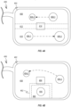
- FIG. 1 shows an exemplary user wearing an augmented reality (AR) device 100.
- AR device 100 can be configured to display virtual content that appears to be located in various locations across a room 102.
- virtual content 104 can be overlaid across a wall-mounted object 106.
- Wall mounted object 106 can take the form of a picture or television mounted to a wall of room 102. In this way, an appearance of wall-mounted object 106 can be altered by virtual content 104.
- AR device 100 could be configured to project virtual content 108 on couch 110 in a way that creates the impression that an object or personage is resting on the couch.
- a depth detection sensor can be used to characterize the distance of various objects from the user. Information retrieved by the depth sensor can then be used to establish a distance for virtual content associated with objects adjacent to the virtual content. This becomes more complex when the virtual objects change distances from AR device 100.
- virtual content 112 can take the form of a walking person taking a motion path that takes the person around table 114. Data retrieved by the depth sensor of AR device 100 can be used to define a motion path that avoids table 114 as virtual content 112 moves from position 112-1 to position 112-2. To accurately portray the position of virtual content 112 across its entire motion path, the perceived distance between AR device 100 and virtual content 112 should be constantly reduced.
- FIG. 2A shows a display system 200 capable of displaying projected content at any distance.
- a projector 202 can display virtual content upon tunable lens 204.
- Tunable lens 204 can then change its optical configuration to adjust a depth at which the projected content is displayed.
- Tunable lens 204 could leverage any of a number of technologies, including e.g., a liquid crystal lens.
- tunable lens 204 is a liquid crystal lens
- the lens can be configured to change its phase profile in accordance with an amount of voltage applied to the liquid crystal lens. While this configuration works well to adjust the depth of the virtual content, light arriving from real-world objects 206 and 208 would be undesirably distorted.
- an apparent position of real-world objects 206 and 208 could be shifted closer or farther from the user as indicated by the two-headed arrows. For this reason, use of display system 200 with an AR device could be problematic because of the undesired distortion of light from real-world objects since one object of augmented reality is for the user to be able to maintain sight of a majority of the real world.
- FIG. 2B shows a display system 250 capable of adjusting the apparent distance to virtual content without affecting the appearance of real-world content. This is accomplished by projecting virtual data between tunable lenses 254 and 256 with a waveguide 258 that redirects light from projector 252 between tunable lenses 254 and 256 and then through tunable lens 254 and towards the eye of a user. In this way, the light emitted by projector 252 can be adjusted by tunable lens 254. Tunable lens 256 can be configured to adjust in a manner opposite to tunable lens 254. The effect of this is that any light originating from real-world objects 206 or 208 can pass through depth display system 250 substantially unaffected. In this way, the virtual content from projector 252 can be the only content that undergoes a focus shift, resulting in a shift in apparent position limited to the virtual content emitted by the projector.
- tunable lens 256 can be configured to prevent any changes made by tunable lens 254 from being applied to the perception of real-world objects
- tunable lens 256 can be configured to cooperate with tunable lens 254 to, e.g., correct a user's vision.
- a vision correction could result in a multi-diopter change being applied by tunable lens 256 that could be equally applied to real-world objects 206 and 208 on account of tunable lens 256 not fully cancelling out the effects of tunable lens 254.
- tunable lens 254 could be reconfigured to apply a +2 diopter adjustment.
- Tunable lens 256 could then apply no diopter adjustment at all so that both virtual content 210 and real-world objects undergo a +2 diopter change, thereby allowing a user normally in need of a +2 diopter vision correction to wear display system 250 without needing any additional vision correction.
- movement of virtual content 210 could involve changing the diopter adjustment of tunable lens 254 to +3 and the diopter adjustment of tunable lens 256 to -1 in order to maintain a +2 diopter offset for vision correction.
- tunable lens 254 could be configured to apply an astigmatism adjustment that is not canceled out by tunable lens 256.
- the tunable lenses can be configured to purposefully throw real-world objects out of focus to allow a user to focus on virtual content 210-1.
- the tunable lenses can be configured to purposefully throw real-world objects out of focus to allow a user to focus on virtual content 210-1.
- the system would allow the system to mask out any distracting real-world stimulus without having to generate light to block the field of view across the entire display. In this way, the tunable optics can be used to shape the augmented reality experience.
- FIG. 3 shows a top view of one specific configuration in which diffractive optics of a waveguide are arranged to guide three different colors of light emitted by a projector between tunable lenses and then towards a user.
- waveguide 302 can include three discrete light paths 304-1, 304-2 and 304-3 for different colors of light such as, e.g., red green and blue.
- Each of light paths 304 can utilize diffractive optics to direct light from a projector 306 between tunable lenses 308 and 310 and then out through tunable lens 310 towards the eye of a user.
- Waveguide 302 can be arranged in a way that causes the resulting virtual content to appear to be positioned at infinity when tunable lens 310 is not applying any changes to the light coming from waveguide 302.
- tunable lens 310 could be configured to decrease the apparent distance between the user and the virtual content being projected through the diffractive optics by varying amounts based on a desired position of the virtual content with respect to the user and other real-world objects. As depicted, the light from real-world objects remains substantially unaffected by tunable lenses 308 and 310 while the light passing through waveguide 302 is affected by tunable lens 310.
- FIGS. 4A - 4B show a transparent display 402 of an AR device 400 displaying first virtual content 404 and second virtual content 406.
- FIG. 4A depicts arrows that show how virtual content 404 and 406 move across transparent display 402 over a particular period of time. During this movement, virtual content 404 travels farther away from AR device 400 and virtual content 406 travels closer to AR device 400. Because transparent display 402 includes tunable lenses for adjusting the apparent depth of the virtual content, an upper region 408 of transparent display 402 can be optically configured to display virtual content 404 moving farther away from AR device 400 and lower region 410 can be configured to display-virtual content 406 moving closer to AR device 400.
- Transition region 412 can take the form of a region where the shape of the tunable lenses is gradually adjusted to accommodate the different optical configurations and prevent the appearance of a visual seam between upper and lower regions 408 and 410. Transition region 412 can be larger or smaller depending on the amount of difference between regions 408 and 410. While real-world object 414 is positioned within transition region 412, it should be appreciated that when transparent display 402 includes two tunable lenses that cooperate to prevent distortion of real-world objects that even transition region 412 would have little to no effect on the appearance of real-world object 414. For this reason, a processor of AR device 400 attempting to determine suitable areas of display 402 for upper region 408 and lower region 410 would only need to consider the path of motion for the virtual content when determining how to vary the optical configuration for independently moving virtual content.
- FIG. 4B shows an exemplary embodiment where virtual content 454 is in motion and virtual content 456 remains stationary.
- motion region 458 can take up most of the viewable area of transparent display 402, while stationary region 460 can take up a much smaller area that limited primarily to virtual content 456.
- motion region 458 can alter an apparent distance between AR device 400 and virtual content 454, while stationary region 460 can maintain the apparent distance to virtual content 456.
- This narrow stationary region 460 can be even more convenient where head movement of the user is deemed unlikely or where the location of the virtual content within transparent display 402 is not governed by head movement of the user.
- virtual content 456 could take the form of status information such as time of day, battery charge or navigation information. This type of information could be distracting if it were also to move with whatever other virtual content the user was interacting with.
- status information such as time of day, battery charge or navigation information. This type of information could be distracting if it were also to move with whatever other virtual content the user was interacting with.
- real-world content 464
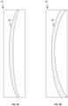
- FIGS. 5A - 5B show side views of tunable lens 502 and how tunable lens 502 can be adjusted to accommodate different virtual content positions.
- FIG. 5A shows how tunable lens 502 can be substantially rectangular in shape and form a lens element 504 within the rectangular volume.
- Lens element 504 can be configured to reshape light emitted from a waveguide in order to establish virtual content at a desired distance from a user of an AR device.
- lens element 504 can change shape into lens element 506 in response to a voltage being applied to tunable lens 502.
- the increased depth and curvature of lens element 506 can cause virtual content to appear closer the AR device than lens element 504.
- tunable lens can be configured to change the apparent distance to virtual content viewed from an AR device.
- FIGS. 5C - 5D show how tunable lens 502 can be adjusted to accommodate motion of multiple independently moving objects represented by virtual content.
- FIGS. 5C and 5D can show how tunable lens 502 would have to move to accommodate the virtual content motion depicted in FIGS. 4A - 4B .
- FIG. 5C could correspond to the situation where virtual content 404 and 406 begin at the same distance from an AR device.
- FIG. 5D shows how tunable lens 502 transitions from forming lens element 508 to lens element 510.
- Transition region 516 includes a gradient that smoothly changes the effective thickness of lens element 510 without creating a visible line affecting the real-world view through tunable lens 502.
- FIG. 6 shows a flow chart depicting a method for displaying virtual content at multiple depths using a small form factor AR device.
- a depth sensor of an AR device characterizes real-world objects within a field of view of a user of the AR device by determining a distance between the user and the real-world objects.
- a processor of the AR device is configured to determine a location or motion path for first virtual content relative to the characterized real-world objects.
- an optical configuration of a first tunable lens of the AR device is configured for initial display of the first virtual content.
- an optical configuration of a second tunable lens of the AR device is configured to prevent the first tunable lens from adversely affecting the view of real-world objects.
- the second tunable lens can be complementary to the first tunable lens to cancel effects of the first tunable lens on the appearance of real-world objects.
- certain vision enhancements can be applied by leaving some of the adjustments made by the first tunable lens unchanged.
- the AR device can be configured to check to see whether the first and second virtual content should be the same distance from the user. At 612, AR device can maintain the optical configuration by continuing to adjust the tunable lenses to track the position of the first and second virtual content.
- the processor can be configured to apply different optical configurations to different regions of the AR device display using the tunable lenses.
- the second virtual content can be purposefully left out of focus when the user's attention is meant to be focused on the first virtual content.
- focus can be transitioned to the second virtual content once interaction with the second virtual content is desired by the user or queued by a piece of software being executed by the AR device.
- focus transitions between virtual content at different distance from the user can be queued by eye tracking sensors configured to determine whether the user is focusing on a particular virtual object.
- a user can manually select virtual content for interaction at which point focus could be adjusted to properly depict the distance between the selected virtual object and the user.
- Imaging software can be used to apply a blurring effect to any virtual content projected by the AR device that is outside of the current depth plane to avoid any impression that all virtual content is the same distance from the user.
- FIGS. 7A - 7B show various embodiments configured to direct light from a display device into an eye of a user.
- FIG. 7A shows a top view of display device 700, which includes a light projector 702 and a waveguide 704 configured to redirect light 706 emitted by projector 702 towards an eye 708 of a user. While waveguide 706 can be configured to emit imagery from thousands or even millions of locations, FIG. 7A shows light being emitted from five exemplary locations from which five output cones 710-1 through 710-5 are depicted. Each of output cones 710 represent light emitted from each location being spread across an angle 712, which can be referred to as a service angle.
- each output cone prevents the light exiting waveguide 704 along output cones 710-1 and 710-5 from arriving at eye 708 of the user.
- angle 712 is limited below a desired threshold by certain characteristics of the display technology such as for example the material refractive index of waveguide 706. Additional details regarding light fields and waveguide-based display devices are provided in U.S. Provisional Patent Application No. 62/539,934 , entitled "HIGH RESOLUTION HIGH FIELD OF VIEW DISPLAY".
- FIG. 7B shows how display device 700 can incorporate one or more optical steering components, such as an optical steering device 714 configured to sequentially shift light 706 exiting waveguide 704 in different directions to expand the effective viewing angle 712 to angle 716, as depicted.
- an optical steering device 714 configured to sequentially shift light 706 exiting waveguide 704 in different directions to expand the effective viewing angle 712 to angle 716, as depicted.
- the user's eye 708 is able to view a wider field of view due to the larger effective angle 716 created by shifting output cones 710-1 - 710-5 in different directions.
- the expanded effective angle 716 allows at least some of the light from output cones 710-1 and 710-5 to arrive at the user's eye 708.
- optical steering component 714 can take the form of one or more tunable prisms capable of assuming multiple different optical configurations (e.g.
- Each optical configuration can be configured to shift the direction of output cones 710 in a different direction. While FIG. 7B only shows light 706 being steered in two different directions, it should be appreciated that light 706 can be steered in many other different directions. Furthermore, it should be appreciated that in addition to a tunable prism other optical elements could be configured to redirect light towards the eyes of a user and that the exemplary prism embodiment should not be construed as limiting the scope of the disclosure.
- a polymer dispersed liquid crystal grating or other tunable grating may be implemented as optical steering components and used to steer output cones 710-1 - 710-5 by modifying an angle of TIR waveguided light, an angle at which light is outcoupled by an outcoupling optical element of the waveguide 704, or a combination thereof.
- one or more metasurfaces e.g., made from metamaterials may be implemented as optical steering components.
- optical steering components may be switchable or otherwise controllable to operate in a discrete number of different steering states, and that exemplary tunable optical steering devices should not be construed as limiting the scope of the disclosure.
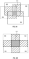
- FIGS. 8A - 8C show exemplary scan patterns that can be generated by a suitable display device and help to expand the field of view of the display device.
- FIG. 8A shows a first scan pattern that includes four different image locations 802, 804, 806 and 808.
- Each of the depicted image locations can represent an aggregate of the light emitted from the display device at a particular point in time.
- light can be delivered to locations 802 - 808 in numerical order.
- An optical steering device can then be used to shift the light back towards the eye of a user in accordance with the active image location. For example, when image location 808 is active the optical steering device can be configured to shift light downwards towards an eye of a user.
- portions of a video frame corresponding to each image location can be sequentially displayed at each of the four location for each frame of the video. For example, when the video source has a frame rate of 1/30 of a second, the corresponding portion of the video frame can be displayed at each location for 1/120 of a second. In this way, an expanded field of view can be achieved without a frame rate reduction. In this way, the resulting image created by the scan pattern maintains a fluid frame rate and also generates a composite image with a substantially higher spatial resolution than would be possible using a single stationary image location.
- an image projector only capable of displaying 480 lines of vertical resolution could reproduce an image or video source with more than 480 lines of resolution using the aforementioned scan techniques. Additional details regarding scan patterns, tiling functionality, and tiled display configurations are provided in U.S. Patent Application No. 14/555,585 .
- FIG. 8A also shows how in some embodiments, portions of adjacent image location can overlap, as indicated by the hashed regions shown in FIG. 8A .
- the overlap can be used to further improve certain aspects of a composite image generated by the display device.
- an increase in resolution within a central region 810 can be achieved by applying one or more super-resolution techniques.
- the portions of each image frame that overlap can be sub-sampled and slightly offset allowing an increase in pixel density in lieu of having pixels stacked atop one another. This produces a super-resolution effect in portions of the display with overlapping regions.
- a display processor is capable of generating 4K resolution imagery (i.e.
- the 4K resolution imagery could be used to achieve the super-resolution effect using an image source normally only capable of generating substantially lower resolutions by distributing the pixels within overlapped regions of the scan pattern.
- each sequentially displayed frame can be associated with a different frame of the video. For example, when playing back a 120 frames per second video source, portions of the display within central region 810 could enjoy the full 120 frames per second frame rate, while non-overlapped regions would only be updated at a rate of 30 frames per second. Overlapped regions near central region 810 could be refreshed at a rate of 60 or 90 frames per second depending on the number of overlapped locations in a particular region.
- FIG. 8B shows a second scan pattern with a large central region 810.
- This second scan pattern results in a ninth of the total image being overlapped by each of image locations 802 - 808.
- a resolution or frame rate within central region 810 can be substantially greater than in the non-overlapped regions.
- the depicted scan pattern can achieve a resolution or frame rate increase of up to four times, which corresponds generally to the number of overlapping frames.
- This type of scan pattern can be particularly beneficial when content of interest is located in the central region of the display.
- the scan pattern can be changed to create increasing amounts of overlap in situations where less virtual content is being presented in peripheral regions of the display.
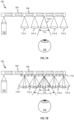
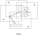
- FIG. 8C shows how imagery positioned in each of image locations 802 - 808 cooperatively generates a composite image 812 that as depicted takes the form of a desk lamp.
- the sequential display of imagery at each of image locations 802 - 808 allows optical properties of the display to be changed in accordance with which of image locations 802 - 808 is currently active during a given scan. For example, when imagery is being displayed at image location 804, the optical properties could be adjusted to shift light representing the base of lamp 812 up towards the user's eye.
- the location of the scan pattern can be positioned in a location of the display that places a virtual image such as lamp 812 within a central region of the scan pattern. This allows central and/or important features of the image to be displayed in a larger number of the image locations.
- FIGS. 9A - 9C show how the first scan pattern depicted in FIG. 8A can be shifted around within display region 900.
- FIG. 9A shows the first scan pattern in the upper left corner of display region 900 at a time t 0 .
- FIG. 9B shows the first scan pattern shifted towards the upper right corner of display region 900 at a time t 1 .
- the display device can include an eye gaze tracker. Sensor data provided by the eye gaze tracker can be utilized to shift the scan pattern to a location within display region 900 corresponding to a user's current focus point. In some embodiments, this sensor data can help keep central region 810 in a location that covers a user's foveal vision (i.e.
- FIG. 9C shows the first scan pattern shifted again towards a lower portion of display region 900.
- FIGS. 9A - 9C also shows how image locations 802 - 808 can change in accordance with the position of the first scan pattern and/or to better represent content being provided to a user. For example, an area across which the first scan pattern extends could be reduced in order to better represent a virtual image that is much smaller than the standard scan pattern size. In some embodiments, changing the scan pattern can help to optimize overlapping regions of the scan pattern for a particular representation of virtual content.
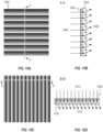
- FIGS. 10A - 10E show various phase profiles for an optical steering device similar to optical steering device 714.
- FIG. 10A shows a front view of an exemplary optical steering device 1002 in a first optical configuration 1004 for shifting light vertically.
- FIG. 10B shows a cross-sectional side view of optical steering device 1002 in accordance with section line A-A.
- Optical steering device 1002 can take the form of a liquid crystal lens capable of changing its phase profile in accordance with an amount of voltage applied to the liquid crystal lens. More specifically, optical steering device 1002 may include two conducting layers with structures capable of producing an electric field responsive to application of voltage thereto. In this way, optical steering device 1002 can shift between multiple different optical configurations.
- the first optical configuration 1004 can have a phase profile with multiple refractive indexes within optical steering device 1002.
- the local refractive index of the optical steering device 1002 may be tailored to meet a prism function or another desired optical function.
- the optical steering device 1002 may exhibit a relatively large phase gradient (e.g., ⁇ rad/ ⁇ m).
- the refractive index can vary in accordance with a saw-tooth profile, as depicted, each of the teeth can be configured to receive a portion of light 1006 and emit light 1008 in a different direction.
- the size and/or spacing of the teeth can be adjusted to reduce or increase the change in the angle of light passing through optical steering device 1002. For example, the angle of each wedge could be gradually reduced as the pattern of wedges approaches a central region of the display.
- This first optical configuration 1004 could be used to shift frames of a scan pattern located in a lower central region of the display.
- FIG. 10C shows a front view of optical steering device 1002 in a second optical configuration 1010.
- FIG. 10D shows a cross-sectional top view of optical steering device 1002 in the second optical configuration in accordance with section line B-B.
- optical steering device 1002 is configured to shift light 1012 laterally.
- optical steering device 1002 receives light 1012 and outputs laterally shifted light 1014. While both the first and second depicted optical configurations shift the direction of the light they do so only vertically or horizontally. It should be appreciated that in some embodiments, two optical steering devices can be layered atop one another to shift the received light both vertically and horizontally.
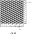
- FIG. 10E shows how by orienting a series of tooth-shaped ridges diagonally across optical steering device 1002, light can be shifted both vertically and horizontally by a single optical steering device 1002.
- FIG. 10E also shows how the depicted diagonal configuration can accomplish the shift in light that would otherwise utilize one-dimensional optical steering devices 1016 and 1018.
- the depicted configuration could be assumed by optical steering device 1002 during frames of a scan pattern in which light exits the waveguide through a lower right region of a display region. It should be noted that while multiple optical configurations have been depicted, optical steering device 1002 can be rearranged in many other configurations that have not been depicted.
- FIGS. 11A - 11B show how an optical steering device can include lenses stacked atop one another to shift incoming light both vertically and horizontally.
- FIG. 11A shows a perspective view of the phase shift of optical steering device 1100, which includes horizontal shift lens 1102 and vertical shift lens 1104. The two lenses can be stacked atop one another in order to redirect light incident to the lenses. This optical configuration allows incoming light to be shifted both vertically and horizontally.
- FIG. 11B shows an optical steering device 1120 having a reduced thickness achieved by using an array of multiple lenses.
- a liquid crystal lens can be used to form an optical configuration equivalent to multiple horizontal shift lenses 1102 and vertical shift lenses 1104, as depicted in FIG. 11B .
- FIGS. 11C - 11D show a cross-sectional side view and top view respectively of a liquid crystal lens 1140 having a Fresnel lens configuration.
- the Fresnel lens configuration can take the form of an optical steering device in order to magnify or de-magnify select virtual content.
- FIG. 11C depicts a Fresnel lens configuration configured to both change the magnification of and laterally shift light passing through liquid crystal lens 1140.
- This type of configuration could be incorporated into any of the optical steering devices described herein.
- a user could request magnification of a particular region of the screen.
- the optical steering device could be configured to form a Fresnel lens configuration over the particular region in order to magnify the content without having to change or update the light generating a particular image stream being viewed by the user.
- FIGS. 12A - 12B show different ways in which optical steering devices can be incorporated into augmented reality display devices.
- the optical steering devices can take the form of liquid crystal lenses capable of selectively changing refractive index in order to change the direction, perspective and/or magnification of light incident thereon.
- FIG. 12A shows a cross-sectional top view of display device 1200.
- Optical steering devices 1202 and 1204 are positioned on opposing sides of waveguide 1206 of display device 1200.
- Waveguide 1206 can include one or more discrete pathways for carrying different colors of light to an eye 1208 of a user of display device 1200.
- Optical steering devices 1202 and 1204 can have a substantially complementary configuration that allows for light 1210 reflected off real-world objects to pass through both optical steering devices to reach eye 1208 in a substantially undistorted manner.
- Light 1212 carried by waveguide 1206 can then be configured to visualize virtual content by undergoing beam steering in accordance with one or more scan patterns without adversely distorting light 1210. The scan patterns and sequential beam steering described previously, increase the effective field of view of display device 1200.
- FIG. 12B shows a wearable display device 1220 according to the invention and how optical steering devices 1202 and 1204 can be incorporated with varifocal lenses 1209 so that both dynamic focus shift and field of view expansion can be applied to light 1212.
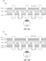
- FIGS. 12C - 12F show display devices configured to receive multiple image streams.
- FIG. 12C shows a top cross-sectional view of display device 1240 includes both waveguide 1206 and waveguide 1244.
- Waveguide 1244 can be configured to carry light 1246, which forms a wide field of view, low-resolution stream of images. As depicted, light 1246 does not undergo any scanning pattern prior to reaching eye 1208.
- Waveguide 1206 can be configured to carry light 1212, which forms a narrow field of view, high-resolution stream of images.
- Light 1212 entering waveguide 1244 can be configured to exit display device 1240 in a region where sensors indicate the user's eyes are focused.
- FIG. 12D shows a front view of display device 1240 , as well as representations of imagery as perceived by the user as light 1212 and 1246 is projected onto the retina of the user's eye 1208.
- FIG. 12D shows a portion of waveguide 1244 capable of emitting light and a region of waveguide 1244 emitting light 1212.
- Light 1212 is depicted producing a narrow field of view image stream that shifts in a scan pattern.
- Light 1246 provides a wide field of view that remains stationary.
- the area across which light 1246 extends represents the maximum viewable area across which light is viewable without an optical steering device.
- a portion of light 1212 can extend outside the region covered by light 1246 on account of light 1212 benefiting from optical steering device 1202, which shifts light 1212 towards eye 1208.
- FIG. 12E shows display device 1260, which adds optical steering devices 1262 and 1264 to the configuration depicted in FIG. 12C .
- light 1212 which generates narrow field of view, high-resolution imagery
- light 1246 which generates wide field of view, low-resolution imagery
- Optical steering device 1262 is configured to independently steer light 1212.
- Optical steering device 1264 is configured to prevent light 1210 and light 1246 from being distorted by the steering of optical steering device 1262.
- Optical steering device 1264 can maintain a phase profile substantially complementary to the phase profile of optical steering device 1262.
- optical steering devices 1202 and 1264 can be combined into a single optical steering device capable of assuming a phase profile that both shifts light 1246 in a desired scan pattern and preemptively compensates for any interference being generated by optical steering device 1262.
- light 1246 and 1212 generated by one or more projectors of display device 1260 can be configured to display streams of imagery at substantially the same spatial resolution.
- Optical steering devices 1202 and 1262 can then be configured to act independently to apply scan patterns to light 1212 and 1246 in order to maximize an effective field of view of display device 1260.
- the separation between waveguides 1206 and 1244 can be configured to generate different apparent distances between the user and virtual content generated by light 1212 and 1246. In this way, depth perception distances can be adjusted without a set of varifocal lenses, as shown in FIG. 12B .
- waveguides at different distances and varifocal lenses can be used in combination to concurrently show virtual content at multiple different apparent distances from eye 1208. The varifocal lenses could then be used to change the apparent distance between eye 1208 and virtual content as previously described.
- FIG. 12F shows a front view of display device 1260, as well as representations of imagery as perceived by the user as light 1212 and 1246 is projected onto the retina of the user's eye 1208.
- FIG. 12F shows how light 1212 can have a narrow field of view that shifts in a first scan pattern and how light 1246 can provide a wide field of view that shifts in a second scan pattern different than the first scan pattern.
- the scan patterns can have the same size and/or resolution. Such a configuration could have the benefit of varying the apparent distance between the user and the virtual content.
- the various aspects, embodiments, implementations or features of the described embodiments can be used separately or in any combination.
- Various aspects of the described embodiments can be implemented by software, hardware or a combination of hardware and software.
- the described embodiments can also be embodied as computer readable code on a computer readable medium for controlling manufacturing operations or as computer readable code on a computer readable medium for controlling a manufacturing line.
- the computer readable medium is any data storage device that can store data, which can thereafter be read by a computer system. Examples of the computer readable medium include read-only memory, random-access memory, CD-ROMs, HDDs, DVDs, magnetic tape, and optical data storage devices.
- the computer readable medium can also be distributed over network-coupled computer systems so that the computer readable code is stored and executed in a distributed fashion.
Landscapes
- Physics & Mathematics (AREA)
- General Physics & Mathematics (AREA)
- Engineering & Computer Science (AREA)
- Optics & Photonics (AREA)
- Theoretical Computer Science (AREA)
- General Engineering & Computer Science (AREA)
- Human Computer Interaction (AREA)
- Computer Hardware Design (AREA)
- Computer Graphics (AREA)
- Software Systems (AREA)
- Geometry (AREA)
- Controls And Circuits For Display Device (AREA)
- Studio Devices (AREA)
- Endoscopes (AREA)
- Indication In Cameras, And Counting Of Exposures (AREA)
- User Interface Of Digital Computer (AREA)
Priority Applications (1)
| Application Number | Priority Date | Filing Date | Title |
|---|---|---|---|
| EP24208456.4A EP4475151A3 (en) | 2017-03-22 | 2018-03-22 | Dynamic field of view variable focus display system |
Applications Claiming Priority (2)
| Application Number | Priority Date | Filing Date | Title |
|---|---|---|---|
| US201762475081P | 2017-03-22 | 2017-03-22 | |
| PCT/US2018/023847 WO2018175780A1 (en) | 2017-03-22 | 2018-03-22 | Dynamic field of view variable focus display system |
Related Child Applications (1)
| Application Number | Title | Priority Date | Filing Date |
|---|---|---|---|
| EP24208456.4A Division EP4475151A3 (en) | 2017-03-22 | 2018-03-22 | Dynamic field of view variable focus display system |
Publications (3)
| Publication Number | Publication Date |
|---|---|
| EP3602583A1 EP3602583A1 (en) | 2020-02-05 |
| EP3602583A4 EP3602583A4 (en) | 2020-07-29 |
| EP3602583B1 true EP3602583B1 (en) | 2024-10-30 |
Family
ID=63582446
Family Applications (2)
| Application Number | Title | Priority Date | Filing Date |
|---|---|---|---|
| EP18771712.9A Active EP3602583B1 (en) | 2017-03-22 | 2018-03-22 | Dynamic field of view variable focus display system |
| EP24208456.4A Pending EP4475151A3 (en) | 2017-03-22 | 2018-03-22 | Dynamic field of view variable focus display system |
Family Applications After (1)
| Application Number | Title | Priority Date | Filing Date |
|---|---|---|---|
| EP24208456.4A Pending EP4475151A3 (en) | 2017-03-22 | 2018-03-22 | Dynamic field of view variable focus display system |
Country Status (9)
| Country | Link |
|---|---|
| US (3) | US10859812B2 (enExample) |
| EP (2) | EP3602583B1 (enExample) |
| JP (2) | JP6957635B2 (enExample) |
| KR (2) | KR102291658B1 (enExample) |
| CN (2) | CN114114691B (enExample) |
| AU (2) | AU2018240367B2 (enExample) |
| CA (1) | CA3056924A1 (enExample) |
| IL (2) | IL310618A (enExample) |
| WO (1) | WO2018175780A1 (enExample) |
Families Citing this family (57)
| Publication number | Priority date | Publication date | Assignee | Title |
|---|---|---|---|---|
| KR102291658B1 (ko) | 2017-03-22 | 2021-08-19 | 매직 립, 인코포레이티드 | 동적 시야 가변 초점 디스플레이 시스템 |
| US11835838B2 (en) | 2017-10-27 | 2023-12-05 | Exciting Technology LLC | System, method and apparatus for non-mechanical optical and photonic beam steering |
| WO2021119165A1 (en) * | 2019-12-09 | 2021-06-17 | Exciting Technology LLC | System, method, and apparatus to steer an electromagnetic beam utilizing staged steering |
| WO2020086692A1 (en) | 2018-10-23 | 2020-04-30 | Exciting Technology LLC | System, method and apparatus for non-mechanical optical and photonic beam steering |
| US12461422B2 (en) | 2017-10-27 | 2025-11-04 | Exciting Technology LLC | System, method, and apparatus to steer an electromagnetic beam utilizing staged steering |
| US10845671B2 (en) | 2017-10-27 | 2020-11-24 | Exciting Technology, Llc | System, method and apparatus for non-mechanical optical and photonic beam steering |
| US11835841B2 (en) | 2017-10-27 | 2023-12-05 | Exciting Technology LLC | System, method and apparatus for non-mechanical optical and photonic beam steering |
| US10989982B2 (en) | 2018-10-23 | 2021-04-27 | Exciting Technology, Llc | System, method and apparatus for non-mechanical optical and photonic beam steering |
| CN107861247B (zh) * | 2017-12-22 | 2020-08-25 | 联想(北京)有限公司 | 光学部件及增强现实设备 |
| US10422989B2 (en) * | 2018-02-06 | 2019-09-24 | Microsoft Technology Licensing, Llc | Optical systems including a single actuator and multiple fluid-filled optical lenses for near-eye-display devices |
| US11245065B1 (en) | 2018-03-22 | 2022-02-08 | Facebook Technologies, Llc | Electroactive polymer devices, systems, and methods |
| US10962791B1 (en) | 2018-03-22 | 2021-03-30 | Facebook Technologies, Llc | Apparatuses, systems, and methods for fabricating ultra-thin adjustable lenses |
| US10690921B1 (en) * | 2018-03-26 | 2020-06-23 | Facebook Technologies, Llc | Apparatuses, systems, and methods for coordinated lens adjustments |
| US10914871B2 (en) | 2018-03-29 | 2021-02-09 | Facebook Technologies, Llc | Optical lens assemblies and related methods |
| US10359845B1 (en) * | 2018-05-01 | 2019-07-23 | Facebook Technologies, Llc | Display assembly using dynamic liquid crystal array |
| US10747309B2 (en) * | 2018-05-10 | 2020-08-18 | Microsoft Technology Licensing, Llc | Reconfigurable optics for switching between near-to-eye display modes |
| US10607353B2 (en) * | 2018-08-30 | 2020-03-31 | Facebook Technologies, Llc | Structured light depth sensing |
| US11227060B1 (en) | 2018-09-12 | 2022-01-18 | Massachusetts Mutual Life Insurance Company | Systems and methods for secure display of data on computing devices |
| US11042649B1 (en) | 2018-09-12 | 2021-06-22 | Massachusetts Mutual Life Insurance Company | Systems and methods for secure display of data on computing devices |
| US10893043B1 (en) | 2018-09-12 | 2021-01-12 | Massachusetts Mutual Life Insurance Company | Systems and methods for secure display of data on computing devices |
| US11015830B2 (en) * | 2018-11-19 | 2021-05-25 | Johnson Controls Technology Company | Device using projector for display |
| US11022835B2 (en) * | 2018-12-15 | 2021-06-01 | Facebook Technologies, Llc | Optical system using segmented phase profile liquid crystal lenses |
| KR102748631B1 (ko) * | 2018-12-18 | 2024-12-31 | 삼성전자주식회사 | 영상을 표시하는 장치, 방법 및 컴퓨터 프로그램 |
| WO2020139754A1 (en) * | 2018-12-28 | 2020-07-02 | Magic Leap, Inc. | Augmented and virtual reality display systems with shared display for left and right eyes |
| US11256331B1 (en) | 2019-01-10 | 2022-02-22 | Facebook Technologies, Llc | Apparatuses, systems, and methods including haptic and touch sensing electroactive device arrays |
| EP3908876B1 (en) | 2019-01-11 | 2025-10-29 | Magic Leap, Inc. | Time-multiplexed display of virtual content at various depths |
| US11467370B2 (en) | 2019-05-27 | 2022-10-11 | Samsung Electronics Co., Ltd. | Augmented reality device for adjusting focus region according to direction of user's view and operating method of the same |
| CN110109255B (zh) * | 2019-06-17 | 2024-11-22 | 杭州光粒科技有限公司 | 基于光波导的扩大ar视场角及减小光机尺度的结构 |
| EP3997512B1 (en) * | 2019-07-12 | 2025-04-30 | Magic Leap, Inc. | Methods and systems for augmented reality display with dynamic field of view |
| WO2021049831A1 (ko) * | 2019-09-09 | 2021-03-18 | 삼성전자 주식회사 | 디스플레이 장치 및 이를 포함한 시스템 |
| KR102788912B1 (ko) | 2019-09-24 | 2025-03-31 | 삼성전자주식회사 | 증강 현실 장치 및 이를 포함하는 웨어러블 장치 |
| CA3156195A1 (en) * | 2019-11-08 | 2021-05-14 | Joseph Ivar Etigson | System and method for implementing a viewer-specific image perception adjustment within a defined view zone, and vision correction system and method using same |
| US11726328B2 (en) * | 2020-01-17 | 2023-08-15 | Meta Platforms Technologies, Llc | Accommodation adjustable and magnification corrective optical system |
| US11294187B2 (en) * | 2020-03-31 | 2022-04-05 | Facebook Technologies, Llc | Thin waveguide beam redirector and display based thereon |
| US12379640B2 (en) | 2020-04-17 | 2025-08-05 | Exciting Technology LLC | System, method, and apparatus for high precision light beam steering using a triplet lens |
| EP4127813B1 (en) | 2020-04-17 | 2025-07-02 | Exciting Technology LLC | Decentered lens light beam steering |
| WO2021246777A1 (en) * | 2020-06-03 | 2021-12-09 | Samsung Electronics Co., Ltd. | Device and method for displaying augmented reality |
| KR102223621B1 (ko) * | 2020-07-01 | 2021-03-05 | 부경대학교 산학협력단 | 비가시광선 가시화 자동정합형 증강현실 글래스 |
| CN112147786B (zh) * | 2020-10-28 | 2024-04-12 | 南京爱奇艺智能科技有限公司 | 一种增强现实显示系统 |
| EP4242726A4 (en) * | 2020-11-09 | 2024-05-08 | Guangdong Oppo Mobile Telecommunications Corp., Ltd. | Image display device and wearable apparatus |
| US11809622B2 (en) | 2020-12-21 | 2023-11-07 | Samsung Electronics Co., Ltd. | Electronic device and method for eye-tracking of user and providing augmented reality service thereof |
| KR20220089023A (ko) * | 2020-12-21 | 2022-06-28 | 삼성전자주식회사 | 전자 장치 및 그의 사용자 시선을 추적하고 증강 현실 서비스를 제공하는 방법 |
| US11928257B2 (en) * | 2021-02-17 | 2024-03-12 | Samsung Electronics Co., Ltd. | Method and electronic device for tracking eye |
| US12073016B2 (en) | 2021-02-23 | 2024-08-27 | Samsung Electronics Co., Ltd. | Electronic device and method of operating the same |
| CN117836695A (zh) * | 2021-08-26 | 2024-04-05 | 谷歌有限责任公司 | 经由可调谐透镜元件的用于遮挡和对比度增强的可变世界模糊 |
| US20240393596A1 (en) * | 2021-09-03 | 2024-11-28 | University Of Central Florida Research Foundation, Inc. | An optical display system and an electronic device |
| CN113960800B (zh) * | 2021-11-08 | 2023-09-29 | 歌尔光学科技有限公司 | 增强现实设备及其屈光度调节方法、存储介质 |
| CN114089835B (zh) * | 2022-01-18 | 2022-04-26 | 湖北工业大学 | 基于自适应视觉差异的混合现实交互式导识系统及方法 |
| KR20230135439A (ko) | 2022-03-16 | 2023-09-25 | 삼성전자주식회사 | 증강 현실 디바이스 및 그 동작 방법 |
| WO2023200920A1 (en) * | 2022-04-13 | 2023-10-19 | Meta Platforms Technologies, Llc | Optical assembly for a head-mount display (hmd) device |
| CN115291417A (zh) * | 2022-07-01 | 2022-11-04 | Oppo广东移动通信有限公司 | 镜片模组、眼镜和可穿戴设备 |
| CN115016139B (zh) * | 2022-07-18 | 2025-02-18 | 未来科技(襄阳)有限公司 | 元宇宙3d显示系统、方法和相关设备 |
| EP4633136A1 (en) * | 2023-03-27 | 2025-10-15 | Samsung Electronics Co., Ltd. | Electronic device and method for providing virtual space image |
| US20250130426A1 (en) * | 2023-10-24 | 2025-04-24 | Google Llc | Active control of virtual image depth positioning |
| US12436725B2 (en) | 2023-10-25 | 2025-10-07 | Samsung Electronics Co., Ltd. | Display device and electronic device including same |
| US12210679B1 (en) | 2024-01-08 | 2025-01-28 | Rockwell Collins, Inc. | Attention redirection within AR/XR immersive environments |
| US12326971B1 (en) | 2024-10-03 | 2025-06-10 | Bansen Labs, Llc | System and method for facilitating adaptive recentering in virtual reality environments |
Family Cites Families (59)
| Publication number | Priority date | Publication date | Assignee | Title |
|---|---|---|---|---|
| US5309272A (en) | 1992-12-11 | 1994-05-03 | Xerox Corporation | Dual pass binary diffractive optical element scanner |
| US5694230A (en) | 1995-06-07 | 1997-12-02 | Digital Optics Corp. | Diffractive optical elements as combiners |
| CN1049288C (zh) * | 1995-11-03 | 2000-02-09 | 邮电部武汉邮电学院研究院 | 自聚焦透镜型可调谐光滤波器单模尾纤准直器的制作方法 |
| WO1998021612A1 (en) * | 1996-11-12 | 1998-05-22 | Planop - Planar Optics Ltd | Optical system for alternative or simultaneous direction of light originating from two scenes to the eye of a viewer |
| JP2000298293A (ja) | 1999-04-15 | 2000-10-24 | Mr System Kenkyusho:Kk | 光変調装置およびそれを用いた3次元像再生装置 |
| US7023594B2 (en) | 2000-06-23 | 2006-04-04 | E-Vision, Llc | Electro-optic lens with integrated components |
| JP2002214545A (ja) * | 2001-01-18 | 2002-07-31 | Olympus Optical Co Ltd | 光学装置 |
| US7110180B2 (en) | 2002-10-09 | 2006-09-19 | Ricoh Company, Ltd. | Diffraction grating, method of fabricating diffraction optical element, optical pickup device, and optical disk drive |
| US7145722B2 (en) | 2003-04-24 | 2006-12-05 | Banpil Photonics, Inc. | Optical filter and method of manufacturing thereof |
| JP3912603B2 (ja) * | 2003-09-05 | 2007-05-09 | ソニー株式会社 | 光導波装置 |
| US7206107B2 (en) | 2004-12-13 | 2007-04-17 | Nokia Corporation | Method and system for beam expansion in a display device |
| US8885139B2 (en) | 2005-01-21 | 2014-11-11 | Johnson & Johnson Vision Care | Adaptive electro-active lens with variable focal length |
| EP1932050A2 (en) | 2005-09-14 | 2008-06-18 | Mirage Innovations Ltd. | Diffractive optical device and system |
| US7817176B2 (en) | 2005-12-26 | 2010-10-19 | Ricoh Company, Ltd. | Light source device, optical scanning device, and image forming apparatus |
| EP1932492B1 (en) * | 2006-12-13 | 2011-09-14 | Akkolens International B.V. | Accommodating intraocular lens with variable correction |
| US20100149073A1 (en) * | 2008-11-02 | 2010-06-17 | David Chaum | Near to Eye Display System and Appliance |
| US20110075257A1 (en) | 2009-09-14 | 2011-03-31 | The Arizona Board Of Regents On Behalf Of The University Of Arizona | 3-Dimensional electro-optical see-through displays |
| US8233204B1 (en) * | 2009-09-30 | 2012-07-31 | Rockwell Collins, Inc. | Optical displays |
| US8248178B2 (en) | 2009-12-03 | 2012-08-21 | The Aerospace Corporation | High power waveguide polarizer with broad bandwidth and low loss, and methods of making and using same |
| US8467643B2 (en) | 2010-08-13 | 2013-06-18 | Toyota Motor Engineering & Mfg. North America, Inc. | Optical device using double-groove grating |
| US20120057235A1 (en) | 2010-09-03 | 2012-03-08 | Massachusetts Institute Of Technology | Method for Antireflection in Binary and Multi-Level Diffractive Elements |
| JP5953311B2 (ja) | 2010-11-08 | 2016-07-20 | シーリアル テクノロジーズ ソシエテ アノニムSeereal Technologies S.A. | 表示装置 |
| US8988463B2 (en) | 2010-12-08 | 2015-03-24 | Microsoft Technology Licensing, Llc | Sympathetic optic adaptation for see-through display |
| US9323325B2 (en) * | 2011-08-30 | 2016-04-26 | Microsoft Technology Licensing, Llc | Enhancing an object of interest in a see-through, mixed reality display device |
| US20130300634A1 (en) | 2012-05-09 | 2013-11-14 | Nokia Corporation | Method and apparatus for determining representations of displayed information based on focus distance |
| EP2859403B1 (en) * | 2012-06-11 | 2022-10-19 | Magic Leap, Inc. | Multiple depth plane three-dimensional display using a wave guide reflector array projector |
| US9645394B2 (en) | 2012-06-25 | 2017-05-09 | Microsoft Technology Licensing, Llc | Configured virtual environments |
| US9380287B2 (en) * | 2012-09-03 | 2016-06-28 | Sensomotoric Instruments Gesellschaft Fur Innovative Sensorik Mbh | Head mounted system and method to compute and render a stream of digital images using a head mounted display |
| US9740006B2 (en) * | 2012-09-11 | 2017-08-22 | Magic Leap, Inc. | Ergonomic head mounted display device and optical system |
| WO2014181419A1 (ja) * | 2013-05-09 | 2014-11-13 | 国立大学法人東京大学 | 可変焦点レンズ |
| US10295338B2 (en) * | 2013-07-12 | 2019-05-21 | Magic Leap, Inc. | Method and system for generating map data from an image |
| WO2015006784A2 (en) * | 2013-07-12 | 2015-01-15 | Magic Leap, Inc. | Planar waveguide apparatus with diffraction element(s) and system employing same |
| US9335548B1 (en) * | 2013-08-21 | 2016-05-10 | Google Inc. | Head-wearable display with collimated light source and beam steering mechanism |
| WO2015081313A2 (en) * | 2013-11-27 | 2015-06-04 | Magic Leap, Inc. | Virtual and augmented reality systems and methods |
| WO2015117023A1 (en) * | 2014-01-31 | 2015-08-06 | Mack Corey | Augmented reality eyewear and methods for using same |
| US10203762B2 (en) * | 2014-03-11 | 2019-02-12 | Magic Leap, Inc. | Methods and systems for creating virtual and augmented reality |
| CN106664400B (zh) * | 2014-05-30 | 2020-08-04 | 奇跃公司 | 用于显示虚拟和增强现实的立体视觉的方法和系统 |
| EP2958074A1 (en) * | 2014-06-17 | 2015-12-23 | Thomson Licensing | A method and a display device with pixel repartition optimization |
| FR3030790B1 (fr) * | 2014-12-19 | 2017-02-10 | Commissariat Energie Atomique | Dispositif optique de projection pour des moyens d'affichage tels que des lunettes a realite augmentee. |
| US20160231567A1 (en) | 2015-02-09 | 2016-08-11 | Pasi Saarikko | Display System |
| US9513480B2 (en) | 2015-02-09 | 2016-12-06 | Microsoft Technology Licensing, Llc | Waveguide |
| WO2016130666A1 (en) * | 2015-02-10 | 2016-08-18 | LAFORGE Optical, Inc. | Lens for displaying a virtual image |
| US20160252727A1 (en) * | 2015-02-27 | 2016-09-01 | LAFORGE Optical, Inc. | Augmented reality eyewear |
| US10156721B2 (en) * | 2015-03-09 | 2018-12-18 | Microsoft Technology Licensing, Llc | User-based context sensitive hologram reaction |
| NZ773817A (en) * | 2015-03-16 | 2022-07-29 | Magic Leap Inc | Methods and systems for diagnosing and treating health ailments |
| US9995857B2 (en) | 2015-04-03 | 2018-06-12 | Avegant Corp. | System, apparatus, and method for displaying an image using focal modulation |
| CN107615136B (zh) * | 2015-04-08 | 2021-05-11 | 迪斯帕列斯有限公司 | 光学透视显示元件和使用这样的元件的设备 |
| WO2016181108A1 (en) | 2015-05-08 | 2016-11-17 | Bae Systems Plc | Improvements in and relating to displays |
| NZ738362A (en) | 2015-06-15 | 2019-08-30 | Magic Leap Inc | Display system with optical elements for in-coupling multiplexed light streams |
| US9939644B2 (en) * | 2015-06-25 | 2018-04-10 | Intel Corporation | Technologies for controlling vision correction of a wearable computing device |
| US10852541B2 (en) * | 2015-07-03 | 2020-12-01 | Essilor International | Methods and systems for augmented reality |
| US10146054B2 (en) | 2015-07-06 | 2018-12-04 | Google Llc | Adding prescriptive correction to eyepieces for see-through head wearable displays |
| CN105068250A (zh) * | 2015-08-12 | 2015-11-18 | 深圳纳德光学有限公司 | 大视场角目镜光学系统 |
| US10297180B2 (en) * | 2015-08-03 | 2019-05-21 | Facebook Technologies, Llc | Compensation of chromatic dispersion in a tunable beam steering device for improved display |
| KR20210032022A (ko) | 2016-05-06 | 2021-03-23 | 매직 립, 인코포레이티드 | 광을 재지향시키기 위한 비대칭 격자들을 가진 메타표면들 및 제조를 위한 방법들 |
| US10725223B2 (en) | 2016-08-22 | 2020-07-28 | Magic Leap, Inc. | Multi-layer diffractive eyepiece with wavelength-selective reflector |
| IL300304B2 (en) | 2016-10-26 | 2024-07-01 | Magic Leap Inc | Outcoupling grating for augmented reality system |
| US10948722B2 (en) | 2016-11-16 | 2021-03-16 | Magic Leap, Inc. | Multi-resolution display assembly for head-mounted display systems |
| KR102291658B1 (ko) | 2017-03-22 | 2021-08-19 | 매직 립, 인코포레이티드 | 동적 시야 가변 초점 디스플레이 시스템 |
-
2018
- 2018-03-22 KR KR1020197030559A patent/KR102291658B1/ko active Active
- 2018-03-22 US US15/933,297 patent/US10859812B2/en active Active
- 2018-03-22 AU AU2018240367A patent/AU2018240367B2/en active Active
- 2018-03-22 IL IL310618A patent/IL310618A/en unknown
- 2018-03-22 IL IL269103A patent/IL269103B2/en unknown
- 2018-03-22 KR KR1020217025699A patent/KR102438618B1/ko active Active
- 2018-03-22 JP JP2019551537A patent/JP6957635B2/ja active Active
- 2018-03-22 EP EP18771712.9A patent/EP3602583B1/en active Active
- 2018-03-22 CA CA3056924A patent/CA3056924A1/en active Pending
- 2018-03-22 CN CN202111417985.4A patent/CN114114691B/zh active Active
- 2018-03-22 WO PCT/US2018/023847 patent/WO2018175780A1/en not_active Ceased
- 2018-03-22 CN CN201880019632.9A patent/CN110447082B/zh active Active
- 2018-03-22 EP EP24208456.4A patent/EP4475151A3/en active Pending
-
2020
- 2020-11-10 US US17/093,784 patent/US12007573B2/en active Active
-
2021
- 2021-10-06 JP JP2021164535A patent/JP2022008883A/ja active Pending
-
2022
- 2022-08-31 AU AU2022224768A patent/AU2022224768A1/en not_active Abandoned
-
2024
- 2024-04-29 US US18/650,003 patent/US20240280827A1/en active Pending
Also Published As
| Publication number | Publication date |
|---|---|
| JP6957635B2 (ja) | 2021-11-02 |
| CN110447082B (zh) | 2021-12-14 |
| AU2018240367B2 (en) | 2022-06-02 |
| CN114114691A (zh) | 2022-03-01 |
| KR20190126895A (ko) | 2019-11-12 |
| US12007573B2 (en) | 2024-06-11 |
| US10859812B2 (en) | 2020-12-08 |
| CN114114691B (zh) | 2024-12-13 |
| EP4475151A3 (en) | 2025-03-19 |
| IL269103B1 (en) | 2024-03-01 |
| IL310618A (en) | 2024-04-01 |
| EP3602583A1 (en) | 2020-02-05 |
| US20210124177A1 (en) | 2021-04-29 |
| US20240280827A1 (en) | 2024-08-22 |
| KR102438618B1 (ko) | 2022-08-30 |
| JP2020514826A (ja) | 2020-05-21 |
| EP4475151A2 (en) | 2024-12-11 |
| AU2022224768A1 (en) | 2022-09-22 |
| EP3602583A4 (en) | 2020-07-29 |
| WO2018175780A1 (en) | 2018-09-27 |
| CA3056924A1 (en) | 2018-09-27 |
| IL269103B2 (en) | 2024-07-01 |
| IL269103A (en) | 2019-11-28 |
| JP2022008883A (ja) | 2022-01-14 |
| KR20210104171A (ko) | 2021-08-24 |
| US20180275394A1 (en) | 2018-09-27 |
| KR102291658B1 (ko) | 2021-08-19 |
| AU2018240367A1 (en) | 2019-10-10 |
| CN110447082A (zh) | 2019-11-12 |
Similar Documents
| Publication | Publication Date | Title |
|---|---|---|
| US12007573B2 (en) | Dynamic field of view variable focus display system | |
| US12360378B2 (en) | Steerable high-resolution display | |
| KR102516095B1 (ko) | 머리-장착 디스플레이 시스템들을 위한 다해상도 디스플레이 어셈블리 | |
| EP3548955B1 (en) | Display apparatus and method of displaying using image renderers and optical combiners | |
| US10775617B2 (en) | Eye tracked lens for increased screen resolution | |
| US20250013069A1 (en) | Light field display device and head-mounted display | |
| JP2018151459A (ja) | ステレオ立体視装置 | |
| HK40005686A (en) | Display apparatus and method of displaying using image renderers and optical combiners | |
| BG2835U1 (bg) | Стереоскопична проекторна система |
Legal Events
| Date | Code | Title | Description |
|---|---|---|---|
| STAA | Information on the status of an ep patent application or granted ep patent |
Free format text: STATUS: THE INTERNATIONAL PUBLICATION HAS BEEN MADE |
|
| PUAI | Public reference made under article 153(3) epc to a published international application that has entered the european phase |
Free format text: ORIGINAL CODE: 0009012 |
|
| STAA | Information on the status of an ep patent application or granted ep patent |
Free format text: STATUS: REQUEST FOR EXAMINATION WAS MADE |
|
| 17P | Request for examination filed |
Effective date: 20191016 |
|
| AK | Designated contracting states |
Kind code of ref document: A1 Designated state(s): AL AT BE BG CH CY CZ DE DK EE ES FI FR GB GR HR HU IE IS IT LI LT LU LV MC MK MT NL NO PL PT RO RS SE SI SK SM TR |
|
| AX | Request for extension of the european patent |
Extension state: BA ME |
|
| RIC1 | Information provided on ipc code assigned before grant |
Ipc: H01F 38/14 20060101AFI20200306BHEP |
|
| DAV | Request for validation of the european patent (deleted) | ||
| DAX | Request for extension of the european patent (deleted) | ||
| A4 | Supplementary search report drawn up and despatched |
Effective date: 20200629 |
|
| RIC1 | Information provided on ipc code assigned before grant |
Ipc: H01F 38/14 20060101AFI20200623BHEP |
|
| STAA | Information on the status of an ep patent application or granted ep patent |
Free format text: STATUS: EXAMINATION IS IN PROGRESS |
|
| 17Q | First examination report despatched |
Effective date: 20221111 |
|
| P01 | Opt-out of the competence of the unified patent court (upc) registered |
Effective date: 20230607 |
|
| GRAP | Despatch of communication of intention to grant a patent |
Free format text: ORIGINAL CODE: EPIDOSNIGR1 |
|
| STAA | Information on the status of an ep patent application or granted ep patent |
Free format text: STATUS: GRANT OF PATENT IS INTENDED |
|
| INTG | Intention to grant announced |
Effective date: 20240506 |
|
| GRAS | Grant fee paid |
Free format text: ORIGINAL CODE: EPIDOSNIGR3 |
|
| GRAA | (expected) grant |
Free format text: ORIGINAL CODE: 0009210 |
|
| STAA | Information on the status of an ep patent application or granted ep patent |
Free format text: STATUS: THE PATENT HAS BEEN GRANTED |
|
| AK | Designated contracting states |
Kind code of ref document: B1 Designated state(s): AL AT BE BG CH CY CZ DE DK EE ES FI FR GB GR HR HU IE IS IT LI LT LU LV MC MK MT NL NO PL PT RO RS SE SI SK SM TR |
|
| REG | Reference to a national code |
Ref country code: GB Ref legal event code: FG4D |
|
| REG | Reference to a national code |
Ref country code: CH Ref legal event code: EP |
|
| REG | Reference to a national code |
Ref country code: IE Ref legal event code: FG4D |
|
| REG | Reference to a national code |
Ref country code: DE Ref legal event code: R096 Ref document number: 602018076004 Country of ref document: DE |
|
| REG | Reference to a national code |
Ref country code: NL Ref legal event code: FP |
|
| REG | Reference to a national code |
Ref country code: LT Ref legal event code: MG9D |
|
| PGFP | Annual fee paid to national office [announced via postgrant information from national office to epo] |
Ref country code: NL Payment date: 20250219 Year of fee payment: 8 |
|
| PG25 | Lapsed in a contracting state [announced via postgrant information from national office to epo] |
Ref country code: PT Free format text: LAPSE BECAUSE OF FAILURE TO SUBMIT A TRANSLATION OF THE DESCRIPTION OR TO PAY THE FEE WITHIN THE PRESCRIBED TIME-LIMIT Effective date: 20250228 Ref country code: IS Free format text: LAPSE BECAUSE OF FAILURE TO SUBMIT A TRANSLATION OF THE DESCRIPTION OR TO PAY THE FEE WITHIN THE PRESCRIBED TIME-LIMIT Effective date: 20250228 Ref country code: HR Free format text: LAPSE BECAUSE OF FAILURE TO SUBMIT A TRANSLATION OF THE DESCRIPTION OR TO PAY THE FEE WITHIN THE PRESCRIBED TIME-LIMIT Effective date: 20241030 |
|
| PGFP | Annual fee paid to national office [announced via postgrant information from national office to epo] |
Ref country code: DE Payment date: 20250218 Year of fee payment: 8 |
|
| PG25 | Lapsed in a contracting state [announced via postgrant information from national office to epo] |
Ref country code: FI Free format text: LAPSE BECAUSE OF FAILURE TO SUBMIT A TRANSLATION OF THE DESCRIPTION OR TO PAY THE FEE WITHIN THE PRESCRIBED TIME-LIMIT Effective date: 20241030 |
|
| REG | Reference to a national code |
Ref country code: AT Ref legal event code: MK05 Ref document number: 1737785 Country of ref document: AT Kind code of ref document: T Effective date: 20241030 |
|
| PG25 | Lapsed in a contracting state [announced via postgrant information from national office to epo] |
Ref country code: BG Free format text: LAPSE BECAUSE OF FAILURE TO SUBMIT A TRANSLATION OF THE DESCRIPTION OR TO PAY THE FEE WITHIN THE PRESCRIBED TIME-LIMIT Effective date: 20241030 |
|
| PG25 | Lapsed in a contracting state [announced via postgrant information from national office to epo] |
Ref country code: ES Free format text: LAPSE BECAUSE OF FAILURE TO SUBMIT A TRANSLATION OF THE DESCRIPTION OR TO PAY THE FEE WITHIN THE PRESCRIBED TIME-LIMIT Effective date: 20241030 |
|
| PG25 | Lapsed in a contracting state [announced via postgrant information from national office to epo] |
Ref country code: NO Free format text: LAPSE BECAUSE OF FAILURE TO SUBMIT A TRANSLATION OF THE DESCRIPTION OR TO PAY THE FEE WITHIN THE PRESCRIBED TIME-LIMIT Effective date: 20250130 |
|
| PG25 | Lapsed in a contracting state [announced via postgrant information from national office to epo] |
Ref country code: LV Free format text: LAPSE BECAUSE OF FAILURE TO SUBMIT A TRANSLATION OF THE DESCRIPTION OR TO PAY THE FEE WITHIN THE PRESCRIBED TIME-LIMIT Effective date: 20241030 Ref country code: GR Free format text: LAPSE BECAUSE OF FAILURE TO SUBMIT A TRANSLATION OF THE DESCRIPTION OR TO PAY THE FEE WITHIN THE PRESCRIBED TIME-LIMIT Effective date: 20250131 Ref country code: AT Free format text: LAPSE BECAUSE OF FAILURE TO SUBMIT A TRANSLATION OF THE DESCRIPTION OR TO PAY THE FEE WITHIN THE PRESCRIBED TIME-LIMIT Effective date: 20241030 |
|
| PGFP | Annual fee paid to national office [announced via postgrant information from national office to epo] |
Ref country code: BE Payment date: 20250218 Year of fee payment: 8 |
|
| PG25 | Lapsed in a contracting state [announced via postgrant information from national office to epo] |
Ref country code: PL Free format text: LAPSE BECAUSE OF FAILURE TO SUBMIT A TRANSLATION OF THE DESCRIPTION OR TO PAY THE FEE WITHIN THE PRESCRIBED TIME-LIMIT Effective date: 20241030 |
|
| PGFP | Annual fee paid to national office [announced via postgrant information from national office to epo] |
Ref country code: FR Payment date: 20250219 Year of fee payment: 8 |
|
| PGFP | Annual fee paid to national office [announced via postgrant information from national office to epo] |
Ref country code: GB Payment date: 20250221 Year of fee payment: 8 |
|
| PG25 | Lapsed in a contracting state [announced via postgrant information from national office to epo] |
Ref country code: RS Free format text: LAPSE BECAUSE OF FAILURE TO SUBMIT A TRANSLATION OF THE DESCRIPTION OR TO PAY THE FEE WITHIN THE PRESCRIBED TIME-LIMIT Effective date: 20250130 |
|
| PG25 | Lapsed in a contracting state [announced via postgrant information from national office to epo] |
Ref country code: SM Free format text: LAPSE BECAUSE OF FAILURE TO SUBMIT A TRANSLATION OF THE DESCRIPTION OR TO PAY THE FEE WITHIN THE PRESCRIBED TIME-LIMIT Effective date: 20241030 |
|
| PG25 | Lapsed in a contracting state [announced via postgrant information from national office to epo] |
Ref country code: DK Free format text: LAPSE BECAUSE OF FAILURE TO SUBMIT A TRANSLATION OF THE DESCRIPTION OR TO PAY THE FEE WITHIN THE PRESCRIBED TIME-LIMIT Effective date: 20241030 |
|
| PG25 | Lapsed in a contracting state [announced via postgrant information from national office to epo] |
Ref country code: EE Free format text: LAPSE BECAUSE OF FAILURE TO SUBMIT A TRANSLATION OF THE DESCRIPTION OR TO PAY THE FEE WITHIN THE PRESCRIBED TIME-LIMIT Effective date: 20241030 |
|
| PG25 | Lapsed in a contracting state [announced via postgrant information from national office to epo] |
Ref country code: RO Free format text: LAPSE BECAUSE OF FAILURE TO SUBMIT A TRANSLATION OF THE DESCRIPTION OR TO PAY THE FEE WITHIN THE PRESCRIBED TIME-LIMIT Effective date: 20241030 |
|
| PG25 | Lapsed in a contracting state [announced via postgrant information from national office to epo] |
Ref country code: SK Free format text: LAPSE BECAUSE OF FAILURE TO SUBMIT A TRANSLATION OF THE DESCRIPTION OR TO PAY THE FEE WITHIN THE PRESCRIBED TIME-LIMIT Effective date: 20241030 |
|
| PG25 | Lapsed in a contracting state [announced via postgrant information from national office to epo] |
Ref country code: CZ Free format text: LAPSE BECAUSE OF FAILURE TO SUBMIT A TRANSLATION OF THE DESCRIPTION OR TO PAY THE FEE WITHIN THE PRESCRIBED TIME-LIMIT Effective date: 20241030 |
|
| PG25 | Lapsed in a contracting state [announced via postgrant information from national office to epo] |
Ref country code: IT Free format text: LAPSE BECAUSE OF FAILURE TO SUBMIT A TRANSLATION OF THE DESCRIPTION OR TO PAY THE FEE WITHIN THE PRESCRIBED TIME-LIMIT Effective date: 20241030 |
|
| REG | Reference to a national code |
Ref country code: DE Ref legal event code: R097 Ref document number: 602018076004 Country of ref document: DE |
|
| PLBE | No opposition filed within time limit |
Free format text: ORIGINAL CODE: 0009261 |
|
| STAA | Information on the status of an ep patent application or granted ep patent |
Free format text: STATUS: NO OPPOSITION FILED WITHIN TIME LIMIT |
|
| PG25 | Lapsed in a contracting state [announced via postgrant information from national office to epo] |
Ref country code: SE Free format text: LAPSE BECAUSE OF FAILURE TO SUBMIT A TRANSLATION OF THE DESCRIPTION OR TO PAY THE FEE WITHIN THE PRESCRIBED TIME-LIMIT Effective date: 20241030 |
|
| 26N | No opposition filed |
Effective date: 20250731 |
|
| PG25 | Lapsed in a contracting state [announced via postgrant information from national office to epo] |
Ref country code: MC Free format text: LAPSE BECAUSE OF FAILURE TO SUBMIT A TRANSLATION OF THE DESCRIPTION OR TO PAY THE FEE WITHIN THE PRESCRIBED TIME-LIMIT Effective date: 20241030 |
|
| REG | Reference to a national code |
Ref country code: CH Ref legal event code: H13 Free format text: ST27 STATUS EVENT CODE: U-0-0-H10-H13 (AS PROVIDED BY THE NATIONAL OFFICE) Effective date: 20251023 |
|
| PG25 | Lapsed in a contracting state [announced via postgrant information from national office to epo] |
Ref country code: LU Free format text: LAPSE BECAUSE OF NON-PAYMENT OF DUE FEES Effective date: 20250322 |