EP3601867B1 - Anschlussvorrichtung für medienleitungen - Google Patents
Anschlussvorrichtung für medienleitungen Download PDFInfo
- Publication number
- EP3601867B1 EP3601867B1 EP18714492.8A EP18714492A EP3601867B1 EP 3601867 B1 EP3601867 B1 EP 3601867B1 EP 18714492 A EP18714492 A EP 18714492A EP 3601867 B1 EP3601867 B1 EP 3601867B1
- Authority
- EP
- European Patent Office
- Prior art keywords
- latching
- connection
- coupling
- insert part
- locking
- Prior art date
- Legal status (The legal status is an assumption and is not a legal conclusion. Google has not performed a legal analysis and makes no representation as to the accuracy of the status listed.)
- Active
Links
Images









Classifications
-
- F—MECHANICAL ENGINEERING; LIGHTING; HEATING; WEAPONS; BLASTING
- F16—ENGINEERING ELEMENTS AND UNITS; GENERAL MEASURES FOR PRODUCING AND MAINTAINING EFFECTIVE FUNCTIONING OF MACHINES OR INSTALLATIONS; THERMAL INSULATION IN GENERAL
- F16L—PIPES; JOINTS OR FITTINGS FOR PIPES; SUPPORTS FOR PIPES, CABLES OR PROTECTIVE TUBING; MEANS FOR THERMAL INSULATION IN GENERAL
- F16L37/00—Couplings of the quick-acting type
- F16L37/56—Couplings of the quick-acting type for double-walled or multi-channel pipes or pipe assemblies
-
- F—MECHANICAL ENGINEERING; LIGHTING; HEATING; WEAPONS; BLASTING
- F16—ENGINEERING ELEMENTS AND UNITS; GENERAL MEASURES FOR PRODUCING AND MAINTAINING EFFECTIVE FUNCTIONING OF MACHINES OR INSTALLATIONS; THERMAL INSULATION IN GENERAL
- F16L—PIPES; JOINTS OR FITTINGS FOR PIPES; SUPPORTS FOR PIPES, CABLES OR PROTECTIVE TUBING; MEANS FOR THERMAL INSULATION IN GENERAL
- F16L37/00—Couplings of the quick-acting type
- F16L37/08—Couplings of the quick-acting type in which the connection between abutting or axially overlapping ends is maintained by locking members
- F16L37/084—Couplings of the quick-acting type in which the connection between abutting or axially overlapping ends is maintained by locking members combined with automatic locking
- F16L37/091—Couplings of the quick-acting type in which the connection between abutting or axially overlapping ends is maintained by locking members combined with automatic locking by means of a ring provided with teeth or fingers
- F16L37/0915—Couplings of the quick-acting type in which the connection between abutting or axially overlapping ends is maintained by locking members combined with automatic locking by means of a ring provided with teeth or fingers with a separate member for releasing the coupling
-
- F—MECHANICAL ENGINEERING; LIGHTING; HEATING; WEAPONS; BLASTING
- F16—ENGINEERING ELEMENTS AND UNITS; GENERAL MEASURES FOR PRODUCING AND MAINTAINING EFFECTIVE FUNCTIONING OF MACHINES OR INSTALLATIONS; THERMAL INSULATION IN GENERAL
- F16L—PIPES; JOINTS OR FITTINGS FOR PIPES; SUPPORTS FOR PIPES, CABLES OR PROTECTIVE TUBING; MEANS FOR THERMAL INSULATION IN GENERAL
- F16L37/00—Couplings of the quick-acting type
- F16L37/08—Couplings of the quick-acting type in which the connection between abutting or axially overlapping ends is maintained by locking members
- F16L37/084—Couplings of the quick-acting type in which the connection between abutting or axially overlapping ends is maintained by locking members combined with automatic locking
- F16L37/098—Couplings of the quick-acting type in which the connection between abutting or axially overlapping ends is maintained by locking members combined with automatic locking by means of flexible hooks
- F16L37/0985—Couplings of the quick-acting type in which the connection between abutting or axially overlapping ends is maintained by locking members combined with automatic locking by means of flexible hooks the flexible hook extending radially inwardly from an outer part and engaging a bead, recess or the like on an inner part
-
- F—MECHANICAL ENGINEERING; LIGHTING; HEATING; WEAPONS; BLASTING
- F16—ENGINEERING ELEMENTS AND UNITS; GENERAL MEASURES FOR PRODUCING AND MAINTAINING EFFECTIVE FUNCTIONING OF MACHINES OR INSTALLATIONS; THERMAL INSULATION IN GENERAL
- F16L—PIPES; JOINTS OR FITTINGS FOR PIPES; SUPPORTS FOR PIPES, CABLES OR PROTECTIVE TUBING; MEANS FOR THERMAL INSULATION IN GENERAL
- F16L5/00—Devices for use where pipes, cables or protective tubing pass through walls or partitions
- F16L5/02—Sealing
- F16L5/027—Sealing by means of a joint of the quick-acting type
-
- F—MECHANICAL ENGINEERING; LIGHTING; HEATING; WEAPONS; BLASTING
- F16—ENGINEERING ELEMENTS AND UNITS; GENERAL MEASURES FOR PRODUCING AND MAINTAINING EFFECTIVE FUNCTIONING OF MACHINES OR INSTALLATIONS; THERMAL INSULATION IN GENERAL
- F16L—PIPES; JOINTS OR FITTINGS FOR PIPES; SUPPORTS FOR PIPES, CABLES OR PROTECTIVE TUBING; MEANS FOR THERMAL INSULATION IN GENERAL
- F16L5/00—Devices for use where pipes, cables or protective tubing pass through walls or partitions
- F16L5/02—Sealing
- F16L5/12—Sealing the pipe being cut in two pieces
-
- F—MECHANICAL ENGINEERING; LIGHTING; HEATING; WEAPONS; BLASTING
- F16—ENGINEERING ELEMENTS AND UNITS; GENERAL MEASURES FOR PRODUCING AND MAINTAINING EFFECTIVE FUNCTIONING OF MACHINES OR INSTALLATIONS; THERMAL INSULATION IN GENERAL
- F16L—PIPES; JOINTS OR FITTINGS FOR PIPES; SUPPORTS FOR PIPES, CABLES OR PROTECTIVE TUBING; MEANS FOR THERMAL INSULATION IN GENERAL
- F16L5/00—Devices for use where pipes, cables or protective tubing pass through walls or partitions
- F16L5/02—Sealing
- F16L5/14—Sealing for double-walled or multi-channel pipes
Definitions
- connection device for media lines in particular a plurality of media lines.
- Connection devices for media lines are known in the prior art in a large number of designs.
- the connection openings serve to connect the fluid channel of the connection device to a media line.
- so-called press-in cartridges are inserted into such connection openings of a coupling element, which are firmly connected to the coupling element within the connection opening and provide a connection interface for a media line.
- media line basically refers to line connections for any flow and/or pressure media, such as gases or liquids.
- Media lines are basically pipes or hoses as well as their connection and connecting elements that are part of a system for conveying a medium.
- such media lines are made of plastic.
- EP 2 733 403 A1 discloses a coupling device for media lines.
- the coupling device has two plate-like coupling supports that can be connected to one another.
- the coupling supports each have receiving openings for the fixed holding of inserted plug parts and socket parts. Retaining inserts can be inserted into the coupling supports, which are fixed in the coupling supports to prevent loosening.
- the multiple coupling has two base plates that can be connected, for example, with a screw connection. Before the base plates are joined together, a coupling part can be locked to each base plate by a locking arm of the base plate engaging in a circumferential groove on the coupling part.
- the coupling device comprises two plate-like coupling parts that can be connected to one another. Each of these coupling parts has receiving openings for inserting and for the fixed holding of plug-in coupling parts.
- EN 20 2005 020 263 A1 discloses a multiple coupling for media lines.
- the multiple coupling comprises two plate-like coupling supports, each of which has several receptacles for inserting and for the fixed holding of plug-in coupling parts.
- EN 10 2015 110 124 A1 discloses a connection device for the detachable connection of plastic pipes.
- a union screw is screwed together with a press-in adapter in a receiving device.
- EN 10 2012 108 791 A1 discloses a construction system for a connection device for media lines.
- a connection body has a connection opening for receiving an inner part.
- Connection devices for media lines are usually preconfigured for the respective application and have predefined interfaces for media lines on the coupling element.
- connection device As soon as a connection device is configured for a specific purpose, no further adjustments can be made. Furthermore, A large number of special individual components must be kept in stock for each configuration, which increases the cost of warehousing and logistics.
- the present invention is therefore based on the object of specifying a connection device which ensures increased flexibility with regard to adaptation to different application requirements as well as simple assembly.
- connection device for a plurality of media lines is in particular a separation point at which a media line can be separated.
- the insert part that can be inserted or has been inserted into the connection opening is detachably held in the connection opening.
- the insert part is "detachably" inserted into the connection opening means that the insert part is not attached within the connection opening and the insert part only rests in the connection opening with the effective sealing and contact forces.
- the insert part can be removed from the connection opening without causing any damage, in particular it can be completely removed from the coupling element without causing any damage.
- the insert part has a connection interface for establishing a connection to a media line, wherein the connection area is designed, for example, as a plug receptacle for a connector plug or as a connecting device for a hose or pipe line.
- the connection interface of the insert part serves to connect the insert part and thus also the fluid channel connected to the connection area of the insert part with a Media line.
- the connection interface has in particular means for sealingly connecting to a pipe or hose line.
- connection opening is essentially circular-cylindrical, in particular with at least two different inner diameters.
- the connection opening is designed as a circular-cylindrical recess with a constant diameter.
- the inner walls of the connection opening are designed in particular parallel to one another in the longitudinal direction.
- the connection opening preferably initially has a section with a first diameter and a first depth, in particular where the first depth corresponds to half the total depth.
- a second section with a smaller diameter then follows in the longitudinal direction of the connection opening, so that a circumferential shoulder - a first stop surface - is formed between the first section and the second section.
- the connection opening is delimited, for example, by a base which opens in particular into the fluid channel.
- connection opening is connected to the fluid channel of the connection device, so that a media line connected to the connection area is automatically connected to the fluid channel or channels of the connection device.
- the insert part has at least one connecting means for connecting to the cover plate.
- the connecting means is designed for positive locking with the cover plate. Because the cover plate can be connected or is connected to the base plate, the insert element is held in the connection opening by the cover plate. Preferably, the cover plate is screwed to the base plate and/or positively connected, in particular locked.
- the connecting means of the insert part is designed as at least two locking hooks.
- the locking means itself does not have to be radially spring-elastic; it is sufficient if the locking means is radially spring-elastic together with the insert part, in particular the insert part base body, i.e. it deflects radially together with at least part of the insert part.
- connection device for media lines has at least two, preferably four, particularly preferably six separate connection openings, wherein an insert part is introduced into each connection opening.
- cover plate also has a number of recesses corresponding to the number of connection openings, so that an insert part is introduced into each recess in the cover plate and connected to the cover plate via the connecting means.
- connection opening extends at least partially in the base plate, i.e. the connection opening is either arranged in the base plate or it is at least arranged in such a way that it extends at least partially through the base plate or at least into the base plate.
- the connection opening does not have to run directly through the base plate, but can also extend indirectly, i.e. in another component, through the base plate.
- connection opening has a plurality of longitudinally extending leakage recesses on its inner circumference at the first end side.
- the advantage of the present invention over the prior art is that, depending on the application, different insert parts can be detachably inserted into the connection opening or openings in order to connect the fluid channel or channels to the media line.
- the insert part is held in the connection opening in a simple manner by the cover plate, so that the insert part can be removed from the connection opening after the cover plate has been removed and can be exchanged.
- the advantage here is that the insert parts with different connection areas can be selected depending on the intended use, which means that the coupling element can be equipped with different, non-destructively removable insert parts at each connection opening, so that the coupling element is very flexible and can be configured modularly. As long as the cover plate is connected to the base plate, the insert part cannot be removed from the connection opening.
- connection opening is formed in the base plate, in particular directly in the base plate.
- the base plate preferably has at least one sleeve-like section that at least partially surrounds the connection opening.
- the base plate is therefore formed by a plate in which the connection opening is formed directly, so that the insert part is inserted into the base plate and held in position by the cover plate.
- the base plate preferably has at least six connection openings. At each connection opening, a sleeve-like section is preferably provided which at least partially surrounds the connection opening and which is in particular circular in shape.
- the base plate has at least one coupling recess, that a coupling element can be inserted or is inserted into the coupling recess and can be connected or is connected to the base plate, and that the connection opening is formed in the coupling element, in particular that the coupling element forms a sleeve-like section that at least partially surrounds the connection opening.
- connection opening or openings that extend through the base plate are formed in a further component, namely in the coupling element, which is connected to the base plate, in particular in a form-fitting manner.
- the coupling element preferably protrudes on one side of the base plate, whereby a sleeve-like section is formed that at least partially surrounds the connection opening.
- the base plate is formed as a simple plate with one or a plurality, in particular six, coupling recesses, wherein the coupling recesses are preferably rotationally symmetrical openings through the base plate.
- the base plate has at least one radially flexible locking element in the coupling recess, in particular two radially flexible locking elements arranged opposite one another, and that a positive connection with the coupling element can be established with the locking element or the locking elements.
- the locking element or the locking elements can deflect radially flexibly, i.e. temporarily increase the diameter of the coupling recess.
- the coupling element is therefore connected to the base plate in such a way that it is guided from the underside of the base plate through the coupling recess, whereby the flexible locking element or the flexible locking elements temporarily increase the diameter and lock in a certain locking position with the coupling element, in particular with a counter-locking means arranged on the coupling element, preferably on an outer circumference of the coupling element.
- connection device provides that the base plate has at least one flexible coupling locking means on the coupling recess, in particular at least two flexible coupling locking means, preferably that each coupling locking means has at least one locking edge arranged tangentially to the coupling recess.
- the coupling locking means is preferably arranged relative to the coupling recess in such a way that the evasive movement that can be achieved through the flexibility takes place in a direction that is not directed towards the central axis of the coupling recess, in particular in the secant direction or tangent direction.
- two coupling locking means are provided, which are arranged in particular offset from one another, so that the evasive movement takes place in two imaginary planes that are parallel to one another.
- the coupling locking means can be locked, for example, with locking projections provided on the coupling element, in particular the locking edges.
- the base plate has a flexible locking means on the coupling recess or on the coupling recesses.
- the locking means is preferably designed as a flexible locking arm that can be moved in the radial direction on the center axis of the coupling recess. In the assembled state, the locking means interacts, for example, in a form-fitting manner with a locking edge on the coupling element.
- the cover plate has at least one cover plate locking means, preferably a plurality of cover plate locking means, particularly preferably two cover plate locking means, for example for positively connecting the cover plate to the base plate and/or for connecting the connection device in an installation situation, for example in a recess in a wall.
- the cover plate locking means are designed as flexible locking arms, e.g. two flexible locking arms, on the cover plate and can interact in a positively locking manner with corresponding locking edges or locking recesses on the base plate in such a way that the cover plate and the base plate are mechanically connected. This is advantageous, for example, in order to achieve a preliminary connection between the cover plate and the base plate for assembly purposes.
- the cover plate and the Base plate screwed together for final fixing.
- at least some of the cover plate locking means are designed to fasten the connection device in an installation situation.
- the connection device can thus be fastened, for example, by positive locking of the cover plate locking means with a wall in a recess in a wall.
- two cover plate locking means are provided for at least provisional locking with the base plate and four cover plate locking means for fastening the connection device.
- the coupling element has at least one counter-latching means on an outer circumference, in particular that the counter-latching means has a first latching projection with a first latching region extending at least partially around the circumference, and that the first latching projection has a first distance in the longitudinal direction from an end face surrounding the connection openings, preferably that the first latching projection has a first radial height, particularly preferably that the first latching projection has a second latching region circumferentially opposite in the first latching region.
- the counter-latching means therefore extends on the outer circumference of the coupling element over at least part of the circumference.
- the first latching projection of the counter-latching means extends in a first latching region and in a second latching region arranged opposite on the circumference.
- the first latching region and the second latching region each extend over approximately a quarter of the circumference.
- the first latching projection has a first radial height.
- the counter-latching means has a second latching projection with a latching area extending at least partially around the circumference, and that the second Locking projection has a second distance in the longitudinal direction from an end face surrounding the connection opening, preferably that the second locking projection has a second radial height, particularly preferably that the second locking projection has a second locking region circumferentially opposite the first locking region.
- first locking regions and the second locking regions of the first locking projection and the second locking projection are arranged parallel to one another.
- the first locking projection and the second locking projection allow two locking positions, namely a pre-locking position and a full locking position, to be realized when locking the coupling element to the base plate, in that the radially flexible locking elements in the coupling recess first lock with the first locking projection, as a pre-locking position, and then with the second locking projection, as a full locking position.
- the counter-latching means has at least two latching projections, in particular at least four latching projections, preferably two latching projections are arranged opposite one another, offset from the longitudinal axis.
- the latching projections serve to fasten the coupling element in the base plate and interact with coupling latching means on the base plate.
- the coupling element preferably has four latching projections, which extend eccentrically in pairs opposite one another, each on a secant to the coupling recess.
- the latching projections preferably extend from the outer circumference of the coupling element in such a way that the ends of the latching projections arranged next to one another lie in a common, imaginary plane.
- the fastening of the coupling element can be improved by mounting the coupling element on a
- the outer circumference has at least one, in particular at least partially circumferential, locking edge, preferably additionally has at least one guide edge and/or a closing edge.
- the locking edge, the closing edge and the guide edge are particularly preferably at different distances from an end face of the coupling element.
- the locking means of the base plate interacts with the locking edge in such a way that the coupling element is held in the coupling recess.
- the locking edge, the closing edge and/or the guide edge are preferably designed such that they at least partially surround the outer circumference of the coupling element.
- the locking edge, the guiding edge and/or the closing edge are preferably designed such that they extend tangentially on the outer circumference of the coupling element.
- the coupling element has at least one radially flexible plate locking means on its outer circumference, and that the plate locking means has an insertion bevel which is inclined in the direction of a second end region facing away from the access of the connection opening, in particular that the coupling element has two identical plate locking means arranged circumferentially opposite one another.
- the plate locking means is designed such that the base plate is held between the counter-locking means and the plate locking means after the coupling element has been mounted in the coupling recess, so that the coupling element cannot emerge from the coupling recess.
- the plate locking means is preferably designed as a radially flexible plate holding arm, in particular two opposing plate holding arms.
- the coupling element consequently clamps the base plate between the counter-locking means and the plate locking means, in particular between the radially flexible locking element in the coupling recess and the counter-locking means.
- the coupling element can in principle be introduced into the coupling recess from both sides, but in particular from the direction in which the flexible locking elements in the coupling recess must give way to the rigid counter-locking means.
- the coupling element can only be introduced into the coupling recess from one direction, namely from the direction in which the flexible plate locking means temporarily deviates in order to then lock positively with the base plate.
- the coupling element preferably has a cylinder-like coupling base body, wherein the connection opening is formed within the coupling base body, wherein the access to the connection opening is formed on a first end side of the coupling base body and the fluid channel with a connection means, in particular a connection mandrel, is formed on a second end side.
- the cylinder-like coupling base body consequently forms the connection opening and connects it at the second end side to a connection means, which is designed in particular as a connection mandrel for connecting a hose or pipe.
- the counter-locking means described above and preferably the plate locking means described are formed on the outer circumference of the cylinder-like coupling base body.
- the plate locking means and the counter-locking means are preferably offset from one another at an angle of approximately 90° and arranged at different heights on the circumference.
- the distance between the locking surfaces of the counter-locking means, in particular the second locking projection, and the plate locking means corresponds approximately to the thickness of the base plate.
- connection opening has at least one step between two different inner diameters.
- a plurality of leakage recesses running in the longitudinal direction are provided on the inner circumference on the smaller inner diameter.
- the leakage recesses serve to audibly and/or visibly direct fluid that escapes, for example in the case of faulty seals, to the outside.
- the majority of the leakage recesses are evenly distributed over the circumference of the connection opening.
- the insert part has at least one insert locking means, wherein the insert locking means can be positively locked to the cover plate, and that the insert locking means is designed as at least two locking hooks, and in particular that the two locking hooks are arranged opposite one another on the circumference.
- the locking hooks lock positively to the cover plate in such a way that the cover plate and the insert part are connected.
- the locking hooks themselves or in combination with at least part of the insert part are radially spring-elastic, so that the locking hooks can initially give way temporarily in order to then lock to the cover plate, in particular the top side of the cover plate.
- the insert part has at least one sleeve-like insert part base body, that the insert part base body has at least two radially flexible holding arms formed in the longitudinal direction from the insert part base body on a first end side so that the connection region is designed as a plug receptacle for interaction with a connection plug of a media line, in particular that at least one locking projection is formed on each of the holding arms.
- the sleeve-like insert part base body extends between a first end side and a second end side. At least two, preferably four, particularly preferably six, in particular eight holding arms are formed on the first end side, which are radially flexible at least in their end regions. In particular, at least one locking projection is formed on each holding arm for interacting with at least one corresponding locking recess on a connector plug.
- the locking means, in particular the locking hooks, for locking the insert part base body to the cover plate are preferably formed on the second end side of the insert part base body.
- the insert part base body preferably has a groove on its outer circumference for receiving a seal, in particular an O-ring seal.
- At least one holding arm has at least one support element on its side opposite the locking projection.
- the support element extends in particular over half the width of the holding arm, preferably over the entire width of the holding arm.
- the support element is arranged approximately on a third of the length, preferably on half the length, of the holding arm starting from the first end side of the insert part.
- the deformation and in particular the bending behavior of the holding arm can be influenced.
- the support element also prevents damage to the holding arm.
- at least one holding arm has a recess, in particular a half-shell-shaped recess, in the area of the first end side of the insert part in order to reduce the deformation resistance of the holding arm or to increase the radial To simplify the evasive movement of the holding arm.
- at least two holding arms, preferably three, four, five or six holding arms have a support element and/or a recess.
- the holding arms arranged next to one another therefore each alternately have a locking projection of the first type, namely with a first, shorter distance from the end side, and the holding arms adjacent to them each have a locking projection of the second type, the distance of which from the first end side of the insert body is greater.
- the locking projections of the first type serve to implement the pre-locking position, the locking projections of the second type to implement the full locking position.
- the holding arms with a locking projection of the second type have a support element on the outside and/or a recess.
- the locking projections with a smaller distance in the longitudinal direction have a lower height than the locking projections with the larger distance in the longitudinal direction.
- the locking projections of the holding arms engage in a locking recess on the connector designed for the pre-locking position.
- the locking projections are designed in such a way that the locking connection remains intact even at maximum system pressure within the fluid channel.
- Leakage paths are preferably defined in the insert part, in particular in the connection interface, in particular via leakage recesses, which in the pre-locking position have a predefined pressure loss. from the fluid channel.
- the pressure loss is designed in such a way that the functionality of the system, for example a vehicle brake, is maintained despite the pressure loss.
- the fluid escaping in the pre-locking position generates a noise that indicates the incompletely plugged connection.
- the locking projections with the greater distance must engage in a corresponding recess on the connector plug.
- a greater assembly force is required due to the different heights of the locking projections, in particular due to the greater height of the locking projections further away.
- the predefined, complete holding forces are achieved for the locking connection, which guarantee complete tightness.
- the insert part has a first, circumferentially arranged retaining projection for contact with an end face surrounding the connection opening and/or a second circumferentially arranged retaining projection for contact with a stop surface arranged in the connection opening.
- the movement of the insert part in the longitudinal direction into the connection opening is thus limited by the first and/or the second circumferentially arranged retaining projection.
- the insert part When force is applied in the longitudinal direction, starting from the cover plate, to the insert part, the insert part is supported on the first retaining projection and/or on the second retaining projection.
- the first retaining projection serves for positive locking with the locking means, in particular the locking hooks.
- the insert part is arranged essentially flush with the surface of the cover plate.
- the second end side of the insert part is therefore essentially flush with the surface of the cover plate. Only the locking means for locking with the cover plate, in particular the locking hooks, protrude locally.
- the insert part comprises at least one mandrel-like support section for at least the end entry into a line, a circumferential toothed ring for fixing the line and a release element for releasing the connection between the toothed ring and the line.
- the connection interface of the insert part designed in this way can therefore directly accommodate the end region of a line and connect it in a sealing manner.
- the release element is pushed longitudinally towards the toothed ring so that the toothed ring is elastically deformed and the jamming with the line is released.
- a further advantageous embodiment provides that the insert part has at least one seal on an outer circumference.
- the seal is arranged in particular in a circumferential groove in the insert part.
- the insert part has a plurality of circumferentially arranged first leakage recesses on a first inner circumference of the connection interface, and/or that the insert part has a plurality of circumferentially arranged second leakage recesses in a second inner circumference. Leakage paths are therefore also formed within the connection interface, so that fluid that escapes unintentionally is visibly directed outwards.
- connection device comprises at least four, preferably at least six connection openings.
- the components of all the above-described embodiments are made of a plastic, in particular a plastic reinforced with glass fibers.
- the coupling element is advantageously made of polybutylene terephthalate with 30% glass fibers (PBT GF30) and/or the insert part is made of polyamide 12 with 30% glass fibers or polyamide 11 with 30% glass fibers.
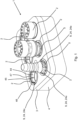
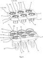
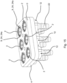
- connection device 1 for media lines in a perspective view.
- the connection device 1 has six insert parts 2, a cover plate 3 and a base plate 4.
- the cover plate 3 is connected to the base plate 4, in particular screwed to the base plate 4.
- the cover plate 3 is additionally positively locked to the base plate 4, in particular at least in a pre-locking position. For example, different connection plugs 5 are inserted into two of the insert parts 2 - the insert parts 2 shown at the front left.
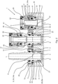
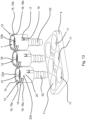
- Fig.2 shows the embodiment of a connection device 1 according to Fig.1 in section view, namely according to Fig.1 through the front row of insert parts 2.
- Six connection openings 7 are provided in the base plate 4, which in this embodiment are formed directly in the base plate 7.
- the base plate 7 is a valve plate.
- the connection openings 7 open into fluid channels 6, wherein the connection openings 7 are designed to at least partially accommodate insert parts 2.
- the insert parts 2 each have a connection interface 8 for establishing a connection to a media line.
- the insert part 2 shown on the far right is an insert part 2 that can directly connect a line and is described in more detail elsewhere.
- the connector plug 5 shown in the middle comprises a connection interface 8 which is designed according to the connection interface 8 of the insert part 2, which in Fig. 2 shown on the far right.
- the insert parts 2 are detachably inserted at least partially into the connection openings 7 and are held in position by the cover plate 3, which is connected to the base plate 4.
- the insert parts 2 also have at least one connecting means 9 with which the cover plate 3 can be connected to the insert part 2.
- the connecting means 9, namely the insert locking means 24, is designed here as two locking hooks 24a, which lock positively to the cover plate 3.
- Fig.3 shows a section through the Fig.1 rear row of connection openings 7 with insert parts 2.
- the insert parts 2 are connected to the The cover plate 3 connected to the base plate 4 is held in the connection openings 7.
- the locking hooks 24a are positively locked to the cover plate 3.
- the insert parts 2 are designed completely identically.
- the insert parts 2 rest with a holding projection 29 on the end face 7a surrounding the connection opening 7.
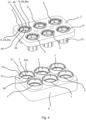
- Fig.4 shows a partial exploded view of a cover plate 3 with insert parts 2 attached to it in a form-fitting manner and the base plate 4, in which the connection openings 7 are formed directly in the base plate 4. Furthermore, the base plate 4 has according to Fig.4 six sleeve-like sections 10 which at least partially surround the connection openings 7. All connection openings 7 with the sleeve-like, collar-like protruding sections 10 are identically designed.
- the insert parts 2 which are positively locked to the cover plate 3 in this illustration are identically designed.
- the insert part 2 in the connection opening 7 at the front right is, in comparison to the Fig.1 and Fig.2 been replaced by another.
- Fig.5 shows the embodiment according to Fig.4 in the assembled state, namely when the cover plate 3 is connected to the base plate 4.
- the insert parts 2 are flush with the surface of the cover plate 3, only the locking hooks 24a protrude slightly. All insert parts 2 inserted into the connection openings 7 are identical.
- the cover plate 3 is screwed to the base plate 4.
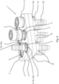
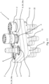
- Fig.6 shows an embodiment of a connection device 1 for media lines in a perspective view.
- the connection device 1 has six connection openings 7, a cover plate 3 and a base plate 4.
- an insert part 2 that is different from the other insert parts 2 is inserted at the front right.
- a connector plug 5 with the connection interfaces 8 (see Fig.8 ) tied together.
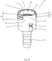
- Fig.7 shows the base plate 4 according to the embodiment of the Fig.6 , namely that the base plate 4 in this embodiment has six coupling recesses 11, and that a coupling element 12 is inserted into each of the coupling recesses 11 and connected to the base plate 4.
- the coupling elements 12 are completely identical, whereby only three are shown here as an example.
- the coupling elements 12 are according to Fig.7 from below into the coupling recesses 11.
- Fig.8 shows the coupling elements 12 mounted in the coupling recesses 11 of the base plate 4, namely positively locked in place, according to Fig.7 .
- Each coupling recess 11 has two oppositely arranged, radially flexible locking elements 13, which form a positive connection with the coupling element 12, in particular a locking element formed on the coupling element 12 and in the Fig.7 and 8
- the locking elements 13 are curved around the central axis of the coupling recess 11 and extend almost over the entire thickness of the base plate 4 (see in particular Fig.7 ).
- the counter-latching means 14 comprises a first latching projection 15 with a first latching region 15a extending partially around the circumference and a second latching projection 16 with a first latching region 16a extending at least partially around the circumference.
- the counter-latching means 14, namely the latching projections 15, 16 are arranged on an outer circumference 20a of the coupling elements 12, in particular of the coupling base body 20.
- the first locking projection 15 has a second locking region 15b and the second locking projection 16 has a second locking region 16b opposite one another on the circumference.
- Fig.7 further shows that the coupling elements 12 each have two oppositely arranged, radially flexible plate locking means 17, each of which has an insertion bevel 19 inclined in the direction of a second end side 18 facing away from the access of the connection opening 7.
- the access to the connection opening 7 is formed on the first end side 21 and the fluid channel 6 with a connection mandrel 22 is formed on the second end side 18.
- On the first end side 21, in the edge area of the connection opening 7, a plurality of leakage recesses 23a oriented parallel to the longitudinal direction are arranged on the coupling elements 12, which allow fluid to escape if the insert part 2 is not inserted correctly or if the seal is faulty.
- the coupling elements 12 have further leakage recesses 23b on the inner circumference 34 below the stop surface 31 arranged in the connection opening 7, which are also oriented parallel to the longitudinal axis L - in the longitudinal direction (see in particular Fig. 12 , Fig. 14 and Fig. 16 ).
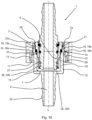
- Fig.9 shows a section through the connection device 1 according to Fig.6 , namely in the area of the connection opening 7 shown at the front left.
- Fig.10 shows a section in the area of the same connection opening 7, but rotated by 90° around the longitudinal axis L.
- Fig.9 shows that the plate locking means 17 are in engagement with the base plate 4. Furthermore, the insert part 2 is held in the connection opening 7 by the cover plate 3, in that the cover plate 3 is connected to the base plate 4.
- Fig.10 shows that the radially flexible locking elements 13 in the coupling recess 11 act from below against the second locking projection 16 of the counter-locking means 14 and thus the coupling element 12 between flexible Locking elements 13 and the plate locking means 17 are held on the base plate 4.
- the locking elements 13 are angled in their end regions so that they can lock both with the first locking projection 15 and with the second locking projection 16.
- Fig. 11 shows - as already stated - an embodiment of a connection device 1 for media lines in a perspective view.
- Fig. 12 shows a section through the embodiment according to Fig. 11 , namely by the front row of insert parts 2.
- the insert parts 2 and connector plugs 5 are identical to the embodiment in Fig. 2
- the base plate 4 has Fig.
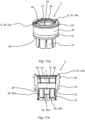
- Fig. 2 , Fig.3 , Fig.9 , Fig.10 , Fig. 12 , Fig. 17a , Fig. 17b and 23 show further that the insert parts 2 preferably have a sleeve-like insert part base body 25 and, on a first end side 26, eight radially flexible holding arms 27 extending from the insert part base body 25 and formed in the longitudinal direction, so that the Connection interface 8 is designed as a plug receptacle for interaction with a connection plug 5 of a media line.
- a locking projection 28 is formed on each holding arm 27, the locking projections 28 on two adjacent holding arms 27 having different distances in the longitudinal direction from the first end side 26 of the insert part base body 25, so that locking projections 28a of the first type and locking projections 28b of the second type are present.
- the locking projections 28a of the first type have a smaller distance in the longitudinal direction than the locking projections 28b of the second type.
- Insert parts 2 or the insert part base bodies 25 have a first circumferentially arranged holding projection 29, which is provided on the one hand for axial positioning within the connection opening 7, and on the other hand for positive locking with the cover plate 3 (see in particular Fig.3 , Fig.9 , Fig.10 and Fig. 12 ).
- the insert part 2 further comprises an insert locking means 24, in particular a radially spring-elastic one, as a connecting means 9, which is designed as two locking hooks 24a.
- the locking hooks 24a interact in a form-fitting manner with the cover plate 3.
- the insert part 2 additionally has a second circumferentially arranged retaining projection 30, which also serves to engage with a stop surface 31 arranged in the connection opening 7 - see Fig.10 - serves.
- a seal 32 in particular an O-ring seal, is provided in a groove 33 on the outer circumference of the insert part 2, which rests in the connection opening 7 in the assembled state.
- the seal 32 is arranged on a shoulder 35 and is secured against loss before assembly, in particular by a projection 36.
- the insert part 2 shown on the far right is used for direct connection to a line (not shown).
- the insert parts 2 each have a mandrel-like support section 37, which is intended for at least partial entry into the end section of a line, and a toothed ring 38 for fixing the line in place by the toothed ring 38 clamping the line around its circumference.
- the insert part 2 also comprises a release element 39, which can be moved parallel to the longitudinal direction of the toothed ring 38 and is used to release the clamping between the toothed ring 38 and a line by elastically deforming the toothed ring 38.
- the support section 37, the toothed ring 38 and the release element 39 are held in the insert part base body 25.
- the insert part 2 further comprises a guide body 40 which is locked to the insert part base body 25 and can be fully inserted into the connection opening 7.
- the guide body 40 also has the groove 33 for the seal 32.
- the insert part 2 also has a main seal 41 which can be placed on the line and a dirt seal 42 arranged on the inlet side. The main seal 41 is held in position by an insert ring 43 which also clamps the toothed ring 38 against the insert part base body 25.
- the insert part 2 or the insert part base body 25 has a plurality of circumferentially arranged first leakage recesses 45 on a first inner circumference 44 of the connection interface 8 and a plurality of circumferentially arranged second leakage recesses 47 in a second inner circumference 46 to form a leakage path.
- the leakage recesses 45, 47 are preferably formed parallel to the longitudinal axis L.
- the cover plate 3 is in a position by means of two cover plate locking means 48, which in this embodiment are designed as flexible locking arms 48c.
- Pre-locking position with the base plate 4 positively locked see Fig. 19 ).
- defined leakage paths are formed.
- a final connection between cover plate 3 and base plate 4 is made by screwing, which also closes the leakage paths.
- the flexible locking arms 48c therefore serve to temporarily connect the cover plate 3 and the base plate 4 for assembly purposes.
- cover plate locking means 48 in this embodiment are designed as flexible locking arms 48a with a rigid frame 48b (see Fig. 19 ).
- the locking arms 48a serve to connect the connection device 1 in an installation situation, for example in a recess in a wall on a vehicle (not shown).
- the locking arms 48a can lock positively into the wall.
- the insert parts 2 have a plurality of first leakage recesses 45 on a first inner circumference 44 and a plurality of second leakage recesses 47 on a second inner circumference 46.
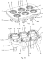
- Fig. 19 shows an embodiment of a connecting device 1 in a partially exploded view, which, with the exception of the insert part 2 at the front right, is like the embodiment according to Fig. 18
- the cover plate 3 has six coupling recesses 11 into which insert parts 2 are inserted.
- the cover plate 3 can be temporarily locked to the base plate 4 by means of the cover plate locking means 48 designed as flexible locking arms 48c.
- the cover plate locking means 48 arranged on the long side are designed as flexible locking arms 48a with a rigid frame 48b and serve to fasten the connection device 1 in an installation situation.
- the base plate 4 has a radially flexible locking element 13 in the coupling recess 11, which locks positively with the coupling element 12.
- two flexible coupling locking means 49 in the form of of locking arms.
- the coupling locking means 49 are arranged offset from one another.
- the coupling locking means 49 of a coupling recess 11 are arranged on two different sides of a plane which contains the three central axes of the front coupling recesses 11.
- the coupling locking means 49 each have a locking edge 50 which is oriented essentially tangentially to the coupling recess 11.
- the base plate 4 has a flexible locking means 51 on each coupling recess 11, here in the form of a radially flexible locking arm. In the assembled state, a coupling element 12 is consequently fixed in the coupling recess 11 by the locking arm 13, the coupling locking means 49 and the locking means 51.
- the coupling elements 12 of the Fig. 18 , Fig. 19 , Fig. 20b and Fig. 21 have according to Fig. 22 via a partially circumferential closing edge 52, a locking edge 53 and a guide edge 54.
- the closing edge 52, the locking edge 53 and the guide edge 54 have different distances from the front edge 7a along the longitudinal axis L.
- the closing edge 52 serves to at least partially close the coupling recess 11.
- the locking means 51 cooperates with the locking edge 53 in a form-fitting manner.
- the coupling locking means 49 which are arranged offset from one another, are provided with their locking edges 50, in particular according to Fig. 20 , in the assembled state with the counter-locking means 14, in particular with a locking projection 55b and a locking projection 55c of the counter-locking means 14.
- Fig. 20a is a partial plan view of the embodiment according to Fig. 18 , especially that of insert part 2 at the front left.
- Fig. 20b shows the positive interaction of the locking edges 50, the coupling locking means 49 and the locking projections 55c and 55b.
- the insert part 2 is on the cover plate 3 held, is introduced into the connection opening 7 of the coupling element 12 and rests against the end face 7a of the coupling element 12.
- a connection plug 5 is introduced into the insert part 2 and is held by the locking projections 28.
- the coupling element 12 has been introduced into the base plate 4 from below, with the coupling base body 20 in front, and locked into place.
- Fig. 21 shows a base plate 4 with six mounted coupling elements 12, each of which is held in the coupling recesses 11 by positive locking of the coupling locking means 49 with two locking projections 55b, 55c of the counter-locking means 14 and the locking means 51 with the second locking edge 53.
- the coupling locking means 49 are arranged offset from one another so that they lock with the locking projections 55b, 55c arranged diagonally to one another.
- a cover plate 3 with insert elements 2 according to Fig. 19 can be mounted and screwed for final fastening.
- the coupling locking means 49 are arranged offset from one another in such a way that, in the assembled state, they interact with a front locking projection 55b and a diagonally opposite, rear locking projection 55c.
- Fig. 22 shows an embodiment of a coupling element 12 according to the Fig. 18 to Fig. 21 .
- the coupling element 12 On its outer circumference 20a, the coupling element 12 has a counter-latching means 14 with four latching projections 55a, 55b, 55c, 55d.
- the latching projections 55a, 55b, 55c, 55d are arranged so that they are opposite one another in pairs and are arranged on a tangent or a secant to the coupling recess 11.
- the latching projections 55a, 55b, 55c, 55d extend so far from the outer circumferential surface 20a that the ends of the latching projections 55a, 55b, 55c, 55d arranged next to one another, namely the latching projections 55a and 55c as well as the latching projections 55b and 55d, each in a common, imaginary plane.
- the connecting mandrel 22 serves to connect the fluid channel 6 to a line (not shown).
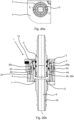
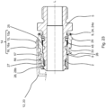
- Fig. 23 shows a further embodiment of an insert part 2 in a sectional side view. The insert part 2 is inserted into a coupling base body 20 of a coupling element 12, which is only partially shown.
- a connector plug 5 is inserted into the connection interface 8 of the insert part 2 and locked into the locking projections 28, 28b of the holding arms 27.
- the support element 56 extends over the entire width of the respective holding arm 27 and serves to support the holding arm on the coupling element 12 in the connection opening 7, in particular to prevent damage to the holding arm 27 in the event of a radial evasive movement.
- the radial deflection movement occurs in particular through or when operating pressure acts on the insert part 2, the connector plug 5 and the other components.
- the support element 56 rests against the inner wall of the coupling element 12 and influences the bending or deformation behavior of the holding arm 27.
- Some of the holding arms 27 also have a recess 57 on the first end side 26 of the insert part 2, which reduces the wall thickness of the holding arm 27 and thereby increases its flexibility.
Landscapes
- Engineering & Computer Science (AREA)
- General Engineering & Computer Science (AREA)
- Mechanical Engineering (AREA)
- Quick-Acting Or Multi-Walled Pipe Joints (AREA)
Description
- Die Erfindung betrifft eine Anschlussvorrichtung für Medienleitungen, insbesondere eine Mehrzahl von Medienleitungen. Anschlussvorrichtungen für Medienleitungen sind im Stand der Technik in einer Vielzahl von Ausgestaltungen bekannt. Bei derartigen Anschlussvorrichtungen dienen die Anschlussöffnungen dem Verbinden des Fluidkanals der Anschlussvorrichtung mit einer Medienleitung. Beispielsweise werden in derartige Anschlussöffnungen eines Kupplungselements sogenannte Einpresspatronen eingesetzt, die innerhalb der Anschlussöffnung fest mit dem Kupplungselement verbunden werden und eine Verbindungsschnittstelle für eine Medienleitung bereitstellen.
- Unter der Bezeichnung "Medienleitung" sind grundsätzlich Leitungsverbindungen für beliebige Strömungs- und/oder Druckmedien, wie Gase oder Flüssigkeiten, zu verstehen. Medienleitungen sind grundsätzlich Rohr- oder Schlauchleitungen sowie deren Anschluss- und Verbindungselemente, die Teil eines Systems zur Führung eines Mediums sind. Insbesondere sind derartige Medienleitungen aus Kunststoff hergestellt.
-
EP 2 733 403 A1 offenbart eine Kupplungseinrichtung für Medienleitungen. Die Kupplungseinrichtung weist zwei plattenartige, miteinander verbindbare Kupplungsträger auf. Die Kupplungsträger weisen jeweils Aufnahmeöffnungen zur fixierten Halterung von eingesetzten Steckerteilen und Muffenteilen auf. In die Kupplungsträger sind Halteeinsätze einsetzbar, die in den Kupplungsträgern gegen Lösen fixiert sind. -
DE 89 08 944 U1 offenbart eine Rohrleitungsmehrfachkupplung mit zwei oder mehr Durchgangsbohrungen. Die Mehrfachkupplung weist zwei Grundplatten auf, die beispielsweise mit einer Schraubverbindung verbindbar sind. Vor dem Zusammenfügen der Grundplatten kann mit jeder Grundplatte ein Kupplungsteil verrastet werden, indem ein Rastarm der Grundplatte in eine umlaufende Nut am Kupplungsteil eingreift. -
DE 20 2005 001 153 U1 offenbart eine Kupplungseinrichtung für Medienleitungen. Die Kupplungseinrichtung umfasst zwei plattenartige, miteinander verbindbare Kupplungsteile. Jedes dieser Kupplungsteile weist Aufnahmeöffnungen zum Einstecken und zur fixierten Halterung von Steckkupplungsteilen auf. -
DE 20 2005 020 263 A1 offenbart eine Mehrfachkupplung für Medienleitungen. Die Mehrfachkupplung umfasst zwei plattenartige Kupplungsträger, die jeweils mehrere Aufnahmen zum Einsetzen und zur fixierten Halterung von Steckkupplungsteilen aufweisen. -
DE 10 2015 110 124 A1 offenbart eine Anschlussvorrichtung zum lösbaren Anschluss von Kunststoff-Rohrleitungen. Eine Überwurfschraube wird zusammen mit einem Einpressadapter in einer Aufnahmeeinrichtung verschraubt. -
DE 10 2012 108 791 A1 offenbart ein Bausystem für eine Anschlussvorrichtung für Medienleitungen. Ein Anschlusskörper weist eine Anschlussöffnung zur Aufnahme eines Innenteils auf. - Anschlussvorrichtungen für Medienleitungen sind üblicherweise für den jeweiligen Einsatzfall vorkonfiguriert und weisen an dem Kupplungselement vordefinierte Schnittstellen für Medienleitungen auf.
- Sobald eine Anschlussvorrichtung also für einen bestimmten Einsatzzweck konfiguriert ist, lassen sich folglich keine Anpassungen mehr vornehmen. Ferner muss für jede Konfiguration eine Vielzahl von speziellen Einzelkomponenten vorgehalten werden, was den Aufwand für Lagerhaltung und Logistik steigert.
- Der vorliegenden Erfindung liegt daher die Aufgabe zu Grunde, eine Anschlussvorrichtung anzugeben, die eine gesteigerte Flexibilität bezüglich der Anpassung an unterschiedliche Einsatzanforderungen sowie eine einfache Montage gewährleistet.
- Die vorgenannte Aufgabe ist mit einer Anschlussvorrichtung gemäß Anspruch 1 gelöst.
- Bei der Anschlussvorrichtung für eine Mehrzahl an Medienleitungen handelt es sich insbesondere um eine Trennstelle, an der eine Medienleitung auftrennbar ist. Das in die Anschlussöffnung einbringbare bzw. eingebrachte Einsatzteil ist lösbar in der Anschlussöffnung gehalten.
- Dass das Einsatzteil "lösbar" in die Anschlussöffnung eingebracht ist, bedeutet, dass keine Befestigung des Einsatzteils innerhalb der Anschlussöffnung erfolgt und das Einsatzteil lediglich mit den wirkenden Dicht- und Anlagekräften in der Anschlussöffnung anliegt. Das Einsatzteil ist zerstörungsfrei aus der Anschlussöffnung entnehmbar, insbesondere vollständig zerstörungsfrei von dem Kupplungselement entfernbar.
- Das Einsatzteil weist eine Verbindungsschnittstelle zum Herstellen einer Verbindung mit einer Medienleitung auf, wobei der Verbindungsbereich beispielsweise als Steckeraufnahme für einen Anschlussstecker oder als Verbindungsvorrichtung für eine Schlauch- oder Rohrleitung ausgebildet ist. Die Verbindungsschnittstelle des Einsatzteils dient dem Verbinden des Einsatzteils und damit auch dem mit dem Verbindungsbereich des Einsatzteils in Verbindung stehenden Fluidkanal mit einer Medienleitung. Die Verbindungsschnittstelle weist insbesondere Mittel zum dichtenden Verbinden mit einer Rohr- oder Schlauchleitung auf.
- Die Anschlussöffnung ist im Wesentlichen kreiszylindrisch, insbesondere mit mindestens zwei unterschiedlichen Innendurchmessern ausgebildet. Beispielsweise ist die Anschlussöffnung als kreiszylindrische Ausnehmung mit konstantem Durchmesser ausgebildet. Die Innenwandungen der Anschlussöffnung sind in Längsrichtung insbesondere parallel zueinander ausgebildet. Vorzugsweise weist die Anschlussöffnung ausgehend von einem Zugang zur Anschlussöffnung - dem ersten Endbereich der Anschlussöffnung - zunächst einen Abschnitt mit einem ersten Durchmesser und einer ersten Tiefe auf, insbesondere wobei die erste Tiefe der Hälfte der Gesamttiefe entspricht. In Längsrichtung der Anschlussöffnung folgt daraufhin ein zweiter Abschnitt mit einem geringeren Durchmesser, so dass zwischen dem ersten Abschnitt und dem zweiten Abschnitt ein umlaufender Absatz - eine erste Anschlagfläche - ausgebildet ist. Gegenüberliegend zum Zugang zur Anschlussöffnung, also im zweiten Endbereich der Anschlussöffnung, wird die Anschlussöffnung beispielsweise durch einen Boden begrenzt, der insbesondere in den Fluidkanal mündet.
- Die Anschlussöffnung steht mit dem Fluidkanal der Anschlussvorrichtung in Verbindung, so dass eine an den Verbindungsbereich angeschlossene Medienleitung automatisch mit dem Fluidkanal oder mit den Fluidkanälen der Anschlussvorrichtung in Verbindung steht.
- Das Einsatzteil weist mindestens ein Verbindungsmittel zum Verbinden mit der Deckplatte auf. Das Verbindungsmittel ist zur formschlüssigen Verrastung mit der Deckplatte ausgebildet. Dadurch, dass die Deckplatte mit der Grundplatte verbindbar bzw. verbunden ist, wird das Einsatzelement durch die Deckplatte in der Anschlussöffnung gehalten. Vorzugsweise ist die Deckplatte mit der Grundlatte verschraubt und/oder formschlüssig verbunden, insbesondere verrastet. Das Verbindungsmittel des Einsatzteils ist als mindestens zwei Rasthaken ausgebildet. Dabei muss das Rastmittel selbst nicht radial-federelastisch sein; es genügt, wenn das Rastmittel zusammen mit dem Einsatzteil, insbesondere dem Einsatzteilgrundkörper, radial-federelastisch ist, also zusammen mit zumindest einem Teil des Einsatzteils radial ausweicht.
- Vorzugsweise weist die Anschlussvorrichtung für Medienleitungen mindestens zwei, bevorzugt vier, besonders bevorzugt sechs separate Anschlussöffnungen auf, wobei in jede Anschlussöffnung jeweils ein Einsatzteil eingebracht ist. Insbesondere weist die Deckplatte ebenfalls eine der Anzahl an Anschlussöffnungen entsprechende Anzahl an Ausnehmungen auf, so dass in jede Ausnehmung in der Deckplatte ein Einsatzteil eingebracht und mit der Deckplatte über das Verbindungsmittel verbunden ist.
- Die Anschlussöffnung erstreckt sich zumindest teilweise in der Grundplatte, d. h. die Anschlussöffnung ist entweder in der Grundplatte angeordnet oder sie ist zumindest so angeordnet, dass sie sich zumindest teilweise durch die Grundplatte hindurch oder zumindest in die Grundplatte hinein erstreckt. Die Anschlussöffnung muss dazu nicht unmittelbar durch die Grundplatte verlaufen, sondern kann sich auch mittelbar, d. h. in einem anderen Bauteil, durch die Grundplatte erstrecken.
- Die Anschlussöffnung weist auf ihrem Innenumfang an der ersten Endseite eine Mehrzahl in Längsrichtung verlaufender Leckageausnehmungen auf.
- Der Vorteil der vorliegenden Erfindung gegenüber dem Stand der Technik ist, dass in die Anschlussöffnung bzw. in die Anschlussöffnungen je nach Einsatzfall unterschiedliche Einsatzteile lösbar eingesetzt werden können, um den Fluidkanal bzw. die Fluidkanäle mit der Medienleitung zu verbinden. Das Einsatzteil ist auf einfache Weise von der Deckplatte in der Anschlussöffnung gehalten, so dass das Einsatzteil nach Entfernen der Deckplatte aus der Anschlussöffnung entfernt und ausgetauscht werden kann. Dabei ist von Vorteil, dass die Einsatzteile mit unterschiedlichen Verbindungsbereichen je nach Einsatzzweck ausgewählt werden können, wodurch das Kupplungselement an jeder Anschlussöffnung mit unterschiedlichen, zerstörungsfrei lösbaren Einsatzteilen ausgestattet werden kann, so dass das Kupplungselement sehr flexibel und modular konfigurierbar ist. Solange die Deckplatte mit der Grundplatte verbunden ist, kann das Einsatzteil nicht aus der Anschlussöffnung entfernt werden.
- Gemäß einer ersten Ausgestaltung der Anschlussvorrichtung hat sich als besonders vorteilhaft herausgestellt, wenn die Anschlussöffnung in der Grundplatte, insbesondere unmittelbar in der Grundplatte, ausgebildet ist. Bevorzugt weist die Grundplatte mindestens einen die Anschlussöffnung zumindest teilweise umgebenden, hülsenartigen Abschnitt auf.
- Die Grundplatte wird folglich durch eine Platte gebildet, in der die Anschlussöffnung unmittelbar ausgebildet ist, so dass das Einsatzteil in die Grundplatte eingesetzt und von der Deckplatte in ihrer Position gehalten wird. Vorzugsweise weist die Grundplatte mindestens sechs Anschlussöffnungen auf. An jeder Anschlussöffnung ist vorzugsweise ein die Anschlussöffnung zumindest teilweise umgebender, hülsenartiger Abschnitt vorgesehen, der insbesondere kreisrund ausgebildet ist.
- Alternativ dazu hat sich zudem als vorteilhaft herausgestellt, wenn gemäß einer weiteren Ausgestaltung vorgesehen ist, dass die Grundplatte mindestens eine Kupplungsausnehmung aufweist, dass in die Kupplungsausnehmung ein Kupplungselement einsetzbar bzw. eingesetzt ist und mit der Grundplatte verbindbar bzw. verbunden ist, und dass die Anschlussöffnung in dem Kupplungselement ausgebildet ist, insbesondere dass das Kupplungselement einen die Anschlussöffnung zumindest teilweise umgebenden, hülsenartigen Abschnitt ausbildet.
- Die Anschlussöffnung bzw. die Anschlussöffnungen, die sich durch die Grundplatte erstrecken, sind bei diesem Ausführungsbeispiel in einem weiteren Bauteil, nämlich in dem Kupplungselement ausgebildet, das mit der Grundplatte, insbesondere formschlüssig, verbunden ist. Das Kupplungselement steht vorzugsweise auf einer Seite der Grundplatte hervor, wodurch ein hülsenartiger Abschnitt ausgebildet wird, der die Anschlussöffnung zumindest teilweise umgibt. Die Grundplatte ist bei diesem Ausführungsbeispiel als einfache Platte mit einer oder einer Mehrzahl, insbesondere sechs, Kupplungsausnehmungen ausgebildet, wobei die Kupplungsausnehmungen vorzugsweise rotationssymmetrische Durchbrüche durch die Grundplatte sind.
- Gemäß einem weiteren Ausführungsbeispiel der Anschlussvorrichtung ist vorgesehen, dass die Grundplatte in der Kupplungsausnehmung mindestens ein radial flexibles Rastelement, insbesondere zwei gegenüberliegend angeordnete, radial flexible Rastelemente, aufweist, und dass mit dem Rastelement bzw. den Rastelementen eine formschlüssige Verbindung mit dem Kupplungselement herstellbar ist. Das Rastelement bzw. die Rastelemente können radial flexibel ausweichen, d. h. temporär den Durchmesser der Kupplungsausnehmung vergrößern. Das Kupplungselement wird folglich derart mit der Grundplatte verbunden, dass es von der Unterseite der Grundplatte durch die Kupplungsausnehmung hindurchgeführt wird, wodurch das flexible Rastelement bzw. die flexiblen Rastelemente temporär den Durchmesser vergrößern und in einer bestimmten Rastposition mit dem Kupplungselement, insbesondere einem an dem Kupplungselement, bevorzugt an einem Außenumfang des Kupplungselementes, angeordneten Gegenrastmittel, formschlüssig verrasten.
- Eine weitere Ausgestaltung der Anschlussvorrichtung sieht vor, dass die Grundplatte an der Kupplungsausnehmung mindestens ein flexibles Kupplungsrastmittel aufweist, insbesondere mindestens zwei flexible Kupplungsrastmittel aufweist, bevorzugt dass jedes Kupplungsrastmittel mindestens eine tangential zur Kupplungsausnehmung angeordnete Rastkante aufweist. Das Kupplungsrastmittel ist vorzugsweise derart relativ zur Kupplungsausnehmung angeordnet, dass die durch die Flexibilität realisierbare Ausweichbewegung in einer Richtung erfolgt, die nicht auf die Mittelachse der Kupplungsausnehmung gerichtet ist, insbesondere in Sekantenrichtung oder Tangentenrichtung. Vorzugsweise sind zwei Kupplungsrastmittel vorgesehen, die insbesondere versetzt zueinander angeordnet sind, so dass die Ausweichbewegung in zwei zueinander parallelen, gedachten Ebenen erfolgt. Die Kupplungsrastmittel sind beispielweise mit an dem Kupplungselement vorgesehenen Rastvorsprüngen verrastbar, insbesondere die Rastkanten.
- Zudem ist gemäß einem weiteren Ausführungsbeispiel vorgesehen, dass die Grundplatte an der Kupplungsausnehmung bzw. an den Kupplungsausnehmungen ein flexibles Sperrmittel aufweist. Das Sperrmittel ist vorzugsweise als flexibler Rastarm ausgebildet, der in radialer Richtung auf die Mittelachse der Kupplungsausnehmung bewegbar ist. Im Montagezustand wirkt das Sperrmittel beispielweise formschlüssig mit einer Rastkante am Kupplungselement zusammen.
- Des Weiteren hat sich gemäß einer weiteren Ausgestaltung als vorteilhaft herausgestellt, wenn vorgesehen ist, dass die Deckplatte mindestens ein Deckplattenrastmittel, vorzugsweise eine Mehrzahl an Deckplattenrastmitteln, besonders bevorzugt zwei Deckplattenrastmittel, zum, beispielsweise formschlüssigen, Verbinden der Deckplatte mit der Grundplatte und/oder zum Verbinden der Anschlussvorrichtung in einer Einbausituation, beispielsweise in einer Ausnehmung in einer Wandung, aufweist. Beispielsweise sind die Deckplattenrastmittel als flexible Rastarme, z. B. zwei flexible Rastarme, an der Deckplatte ausgebildet und können formschlüssig mit entsprechenden Rastkanten oder Rastausnehmungen an der Grundplatte derart zusammenwirken, dass die Deckplatte und die Grundplatte mechanisch verbunden sind. Dies ist beispielsweise vorteilhaft, um eine vorläufige Verbindung zwischen Deckplatte und Grundplatte zu Montagezwecken zu erreichen. Vorzugsweise werden die Deckplatte und die Grundplatte zur endgültigen Fixierung miteinander verschraubt. Zudem ist vorgesehen, dass zumindest ein Teil der Deckplattenrastmitttel, beispielsweise vier Rastarme, zum Befestigen der Anschlussvorrichtung in einer Einbausituation ausgebildet sind. Die Anschlussvorrichtung kann somit beispielsweise durch formschlüssiges Verrasten der Deckplattenrastmittel mit einer Wandung in einer Ausnehmung in einer Wandung befestigt werden. Vorzugsweise sind zwei Deckplattenrastmittel zum zumindest vorläufigen Verrasten mit der Grundplatte und vier Deckplattenrastmittel zum Befestigen der Anschlussvorrichtung vorgesehen.
- Gemäß einem weiteren Ausführungsbeispiel ist vorgesehen, dass das Kupplungselement auf einem Außenumfang mindestens ein Gegenrastmittel aufweist, insbesondere dass das Gegenrastmittel einen ersten Rastvorsprung mit einem sich zumindest teilumfänglich erstreckenden ersten Rastbereich aufweist, und dass der erste Rastvorsprung einen ersten Abstand in Längsrichtung von einer die Anschlussöffnungen umgebenden Stirnfläche aufweist, bevorzugt dass der erste Rastvorsprung eine erste radiale Höhe aufweist, besonders bevorzugt dass der erste Rastvorsprung einen im ersten Rastbereich umfänglich gegenüberliegenden, zweiten Rastbereich aufweist.
- Das Gegenrastmittel erstreckt sich folglich auf dem Außenumfang des Kupplungselementes zumindest über einen Teil des Umfangs. Insbesondere erstreckt sich der erste Rastvorsprung des Gegenrastmittels in einem ersten Rastbereich sowie in einem gegenüberliegend auf dem Umfang angeordneten zweiten Rastbereich. Vorzugsweise erstrecken sich der erste Rastbereich und der zweite Rastbereich jeweils über etwa ein Viertel des Umfangs. Der erste Rastvorsprung weist eine erste radiale Höhe auf.
- Zudem ist gemäß einer weiteren Ausgestaltung vorgesehen, dass das Gegenrastmittel einen zweiten Rastvorsprung mit einem sich zumindest teilumfänglich erstreckenden Rastbereich aufweist, und dass der zweite Rastvorsprung einen zweiten Abstand in Längsrichtung von einer die Anschlussöffnung umgebenden Stirnfläche aufweist, bevorzugt dass der zweite Rastvorsprung eine zweite radiale Höhe aufweist, besonders bevorzugt dass der zweite Rastvorsprung einen dem ersten Rastbereich umfänglich gegenüberliegenden, zweiten Rastbereich aufweist.
- Vorzugsweise sind die ersten Rastbereiche und die zweiten Rastbereiche des ersten Rastvorsprungs und des zweiten Rastvorsprungs parallel zueinander angeordnet. Durch den ersten Rastvorsprung und den zweiten Rastvorsprung lassen sich beim Verrasten des Kupplungselementes mit der Grundplatte zwei Raststellungen, nämlich eine Vorraststellung und eine Vollraststellung realisieren, indem die radial flexiblen Rastelemente in der Kupplungsausnehmung zunächst mit dem ersten Rastvorsprung, als Vorraststellung, und anschließend mit dem zweiten Rastvorsprung, als Vollraststellung, verrasten.
- Alternativ oder zusätzlich ist gemäß einer Weiterbildung der Anschlussvorrichtung vorgesehen, dass das Gegenrastmittel mindestens zwei Rastvorsprünge aufweist, insbesondere mindestens vier Rastvorsprünge, bevorzugt dass jeweils zwei Rastvorsprünge versetzt zur Längsachse gegenüberliegend zueinander angeordnet sind. Die Rastvorsprünge dienen dem Befestigen des Kupplungselements in der Grundplatte und wirken mit Kupplungsrastmitteln an der Grundplatte zusammen. Vorzugsweise weist das Kupplungselement vier Rastvorsprünge auf, die sich paarweise gegenüberliegend, jeweils auf einer Sekante an die Kupplungsausnehmung, außermittig erstrecken. Die Rastvorsprünge erstrecken sich vorzugsweise derart vom Außenumfang des Kupplungselements, dass die Enden der nebeneinander angeordneten Rastvorsprünge in einer gemeinsamen, gedachten Ebene liegen.
- Die Befestigung des Kupplungselements lässt sich gemäß einer weiteren Ausgestaltung dadurch verbessern, dass das Kupplungselement auf einem Außenumfang mindestens eine, insbesondere zumindest teilweise umlaufende, Rastkante aufweist, bevorzugt zusätzlich mindestens eine Führungskante und/oder eine Verschlusskante aufweist. Besonders bevorzugt weisen die Rastkante, die Verschlusskante und die Führungskante unterschiedliche Abstände zu einer Stirnfläche des Kupplungselements auf. Beispielweise wirkt im Montagezustand das Sperrmittel der Grundplatte mit der Rastkante derart zusammen, dass das Kupplungselement in der Kupplungsausnehmung gehalten wird.
- Die Rastkante, die Verschlusskante und/oder die Führungskante sind vorzugsweise derart ausgebildet, dass sie den Außenumfang des Kupplungselements zumindest teilweise umlaufend umgeben. Die Rastkante, die Führungskante und/oder die Verschlusskante sind vorzugsweise so ausgebildet, dass sie sich tangential an dem Außenumfang des Kupplungselements erstrecken.
- Ferner ist gemäß einer weiteren bevorzugten Ausgestaltung vorgesehen, dass das Kupplungselement mindestens ein radial flexibles Plattenrastmittel auf seinem Außenumfang aufweist, und dass das Plattenrastmittel eine Einführschräge aufweist, die in Richtung eines zweiten, von dem Zugang der Anschlussöffnung abgewandten Endbereiches geneigt ist, insbesondere dass das Kupplungselement zwei identische, umfänglich gegenüberliegend angeordnete Plattenrastmittel aufweist. Das Plattenrastmittel ist so ausgebildet, dass die Grundplatte nach der Montage des Kupplungselementes in der Kupplungsausnehmung zwischen dem Gegenrastmittel und dem Plattenrastmittel gehalten wird, so dass das Kupplungselement nicht aus der Kupplungsausnehmung heraustreten kann. Bevorzugt ist das Plattenrastmittel als radial-flexibler Plattenhaltearm, insbesondere zwei gegenüberliegende Plattenhaltearme, ausgebildet
- Das Kupplungselement verspannt die Grundplatte folglich zwischen dem Gegenrastmittel und dem Plattenrastmittel, insbesondere zwischen dem radial flexiblen Rastelement in der Kupplungsausnehmung und dem Gegenrastmittel.
- Bei einer Grundplatte mit flexiblen Rastelementen in der Kupplungsausnehmung kann das Kupplungselement grundsätzlich von beiden Seiten in die Kupplungsausnehmung eingebracht werden, insbesondere aber aus der Richtung, bei der die flexiblen Rastelemente in der Kupplungsausnehmung dem starren Gegenrastmittel ausweichen müssen.
- Bei einem Ausführungsbeispiel, bei dem die Platte lediglich rotationssymmetrische - einfache - Kupplungsausnehmungen aufweist, kann das Kupplungselement lediglich aus einer Richtung in die Kupplungsausnehmung eingebracht werden, nämlich aus der Richtung, bei der das flexible Plattenrastmittel temporär ausweicht, um anschließend mit der Grundplatte formschlüssig zu verrasten.
- Gemäß einem weiteren bevorzugten Ausführungsbeispiel der Anschlussvorrichtung weist das Kupplungselement vorzugsweise einen zylinderartigen Kupplungsgrundkörper auf, wobei die Anschlussöffnung innerhalb des Kupplungsgrundkörpers ausgebildet ist, wobei an einer ersten Endseite des Kupplungsgrundkörpers der Zugang zur Anschlussöffnung und an einer zweiten Endseite der Fluidkanal mit einem Anschlussmittel, insbesondere einem Anschlussdorn, ausgebildet ist.
- Der zylinderartige Kupplungsgrundkörper bildet folglich die Anschlussöffnung und verbindet diese an der zweiten Endseite mit einem Anschlussmittel, das insbesondere als Anschlussdorn zum Anschluss einer Schlauch- bzw. Rohrleitung ausgebildet ist. Auf dem Außenumfang des zylinderartigen Kupplungsgrundkörpers sind das vorbeschriebene Gegenrastmittel sowie vorzugsweise die beschriebenen Plattenrastmittel ausgebildet. Vorzugsweise sind die Plattenrastmittel und die Gegenrastmittel in einem Winkel von etwa 90° zueinander versetzt und in unterschiedlichen Höhen auf dem Umfang angeordnet. Der Abstand der Rastflächen des Gegenrastmittels, insbesondere des zweiten Rastvorsprungs, und des Plattenrastmittels entspricht etwa der Dicke der Grundplatte.
- Ferner hat sich gemäß einer weiteren Ausgestaltung als bevorzugt herausgestellt, wenn die Anschlussöffnung mindestens einen Absatz zwischen zwei unterschiedlichen Innendurchmessern aufweist. An dem Innenumfang auf dem kleineren Innendurchmesser sind erfindungsgemäß eine Mehrzahl in Längsrichtung verlaufender Leckageausnehmungen vorgesehen.
- Die Leckageausnehmungen dienen dazu, beispielsweise bei fehlerhaften Dichtungen austretendes Fluid hör- und/oder sichtbar nach außen zu führen. Die Mehrzahl der Leckageausnehmungen ist gleichmäßig über den Umfang der Anschlussöffnung verteilt.
- Um die Verbindung zwischen Einsatzteil und Deckplatte zu verbessern, ist vorgesehen, dass das Einsatzteil mindestens ein Einsatzrastmittel aufweist, wobei das Einsatzrastmittel formschlüssig mit der Deckplatte verrastbar ist, und dass das Einsatzrastmittel als mindestens zwei Rasthaken ausgebildet ist, und insbesondere dass die beiden Rasthaken auf dem Umfang gegenüberliegend zueinander angeordnet sind. Die Rasthaken verrasten derart formschlüssig mit der Deckplatte, dass die Deckplatte und das Einsatzteil verbunden sind. Die Rasthaken sind selbst oder in Kombination mit zumindest einem Teil des Einsatzteils radial federelastisch, so dass die Rasthaken zunächst temporär ausweichen können, um anschließend mit der Deckplatte, insbesondere der Oberseite der Deckplatte, zu verrasten.
- Gemäß einer weiteren Ausgestaltung ist zudem vorgesehen, dass das Einsatzteil mindestens einen hülsenartigen Einsatzteilgrundkörper aufweist, dass der Einsatzteilgrundkörper an einer ersten Endseite mindestens zwei, ausgehend vom Einsatzteilgrundkörper in Längsrichtung ausgebildete, radial flexible Haltearme aufweist, so dass der Verbindungsbereich als Steckeraufnahme zum Zusammenwirken mit einem Anschlussstecker einer Medienleitung ausgebildet ist, insbesondere dass an den Haltearmen jeweils mindestens ein Rastvorsprung ausgebildet ist.
- Der hülsenartige Einsatzteilgrundkörper erstreckt sich zwischen einer ersten Endseite und einer zweiten Endseite. An der ersten Endseite sind mindestens zwei, vorzugsweise vier, besonders bevorzugt sechs, insbesondere acht Haltearme ausgebildet, die zumindest in ihren Endbereichen radial flexibel sind. Insbesondere ist an jedem Haltearm jeweils mindestens ein Rastvorsprung zum Zusammenwirken mit mindestens einem korrespondierenden Rastrücksprung an einem Anschlussstecker ausgebildet. An der zweiten Endseite des Einsatzteilgrundkörpers ist vorzugsweise das Rastmittel, insbesondere die Rasthaken, zum Verrasten des Einsatzteilgrundkörpers mit der Deckplatte ausgebildet. Ferner weist der Einsatzteilgrundkörper vorzugsweise auf seinem Außenumfang eine Nut zur Aufnahme einer Dichtung, insbesondere einer O-Ring-Dichtung, auf.
- Vorzugsweise weist mindestens ein Haltearm an seiner dem Rastvorsprung gegenüberliegenden Seite mindestens ein Stützelement auf. Das Stützelement erstreckt sich insbesondere über die Hälfte der Breite des Haltearms, bevorzugt über die gesamte Breite des Haltearms. Das Stützelement ist etwa auf einem Drittel der Länge, bevorzugt auf der Hälfte der Länge, des Haltearms ausgehend von der ersten Endseite des Einsatzteils angeordnet.
- Mit der Variation des Abstands des Stützelements zur ersten Endseite des Einsatzteils lässt sich das Verformungs- und insbesondere das Biegeverhalten des Haltearms beeinflussen. Das Stützelement verhindert zudem eine Beschädigung des Haltearms. Vorzugsweise weist mindestens ein Haltearm im Bereich der ersten Endseite des Einsatzteils eine, insbesondere halbschalenförmige, Aussparung auf, um den Verformungswiderstand des Haltearms zu reduzieren bzw. die radiale Ausweichbewegung des Haltearms zu vereinfachen. Vorzugsweise weisen mindestens zwei Haltearme, vorzugsweise drei, vier, fünf oder sechs Haltearme ein Stützelement und/oder eine Aussparung auf.
- Als besonders vorteilhaft hat sich gemäß einer weiteren Ausgestaltung zudem herausgestellt, dass an dem Einsatzteilgrundkörper mehr als zwei Haltearme ausgebildet sind, und dass die Rastvorsprünge an zwei nebeneinanderliegenden Haltearmen einen unterschiedlichen Abstand in Längsrichtung zur ersten Endseite des Einsatzteilgrundkörpers aufweisen, insbesondere derart, dass für einen einbringbaren Anschlussstecker eine Vorraststellung und eine Vollraststellung realisierbar ist. Die nebeneinander angeordneten Haltearme weisen folglich jeweils alternierend einen Rastvorsprung erster Art, nämlich mit einem ersten, kürzeren Abstand zur Endseite, und die jeweils danebenliegenden Haltearme einen Rastvorsprung zweiter Art auf, dessen Abstand zur ersten Endseite des Einsatzteilgrundkörpers größer ist. Die Rastvorsprünge erster Art dienen dabei zur Realisierung der Vorraststellung, die Rastvorsprünge zweiter Art zur Realisierung der Vollraststellung. Insbesondere weisen die Haltearme mit einem Rastvorsprung zweiter Art ein Stützelement auf der Außenseite und/oder eine Aussparung auf.
- Beispielsweise haben die Rastvorsprünge mit geringerem Abstand in Längsrichtung eine geringere Höhe als die Rastvorsprünge mit dem größeren Abstand in Längsrichtung.
- Zur Erreichung der Vorraststellung greifen die Rastvorsprünge der Haltearme in einen für die Vorraststellung ausgebildeten Rastrücksprung am Anschlussstecker ein. Für die Vorraststellung sind die Rastvorsprünge so ausgelegt, dass die Rastverbindung auch bei maximalem Systemdruck innerhalb des Fluidkanals bestehen bleibt. Vorzugsweise sind im Einsatzteil, insbesondere in der Verbindungsschnittstelle, Leckagepfade definiert, insbesondere über Leckageausnehmungen, die in der Vorraststellung einen vordefinierten Druckverlust aus dem Fluidkanal zulassen. Vorzugsweise ist der Druckverlust so ausgelegt, dass eine Funktionsweise des Systems, beispielsweise einer Fahrzeugbremse, trotz Druckverlust erhalten bleibt. Bevorzugt ist zudem vorgesehen, dass durch das in der Vorraststellung entweichende Fluid ein Geräusch erzeugt wird, das auf die unvollständig gesteckte Verbindung hinweist.
- Zur Erreichung der Vollraststellung müssen die Rastvorsprünge mit dem größeren Abstand in einen korrespondierenden Rücksprung am Anschlussstecker eingreifen. Bei entsprechenden Ausführungsbeispielen ist aufgrund der unterschiedlichen Höhe der Rastvorsprünge, insbesondere aufgrund der größeren Höhe der weiter entfernten Rastvorsprünge, eine größere Montagekraft erforderlich. In der Vollraststellung werden für die Rastverbindung die vordefinierten, vollständigen Haltekräfte erreicht, die eine vollständige Dichtheit gewährleisten.
- Des Weiteren ist gemäß einer Ausgestaltung der Anschlussvorrichtung vorgesehen, dass das Einsatzteil einen ersten, umfänglich angeordneten Haltevorsprung zur Anlage an eine die Anschlussöffnung umgebende Stirnfläche und/oder einen zweiten umfänglich angeordneten Haltevorsprung zur Anlage an einer in der Anschlussöffnung angeordneten Anschlagfläche aufweist. Die Bewegung des Einsatzteils in Längsrichtung in die Anschlussöffnung wird folglich durch den ersten und/oder den zweiten umfänglich angeordneten Haltevorsprung begrenzt. Bei Krafteinwirkung in Längsrichtung, ausgehend von der Deckplatte, auf das Einsatzteil, stützt sich folglich das Einsatzteil an dem ersten Haltevorsprung und/oder an dem zweiten Haltevorsprung ab. Ferner dient der erste Haltevorsprung dem formschlüssigen Verrasten mit dem Rastmittel, insbesondere den Rasthaken.
- Als besonders vorteilhaft hat sich zudem herausgestellt, wenn gemäß einer Ausgestaltung vorgesehen ist, dass das Einsatzteil im Wesentlichen flächenbündig in der Deckplatte angeordnet ist. Die zweite Endseite des Einsatzteils schließt folglich im Wesentlichen flächenbündig mit der Oberfläche der Deckplatte ab. Lediglich das Rastmittel zum Verrasten mit der Deckplatte, insbesondere die Rasthaken, stehen lokal hervor.
- Besonders vorteilhaft ist ferner, wenn gemäß einem weiteren Ausführungsbeispiel das Einsatzteil mindestens einen dornartigen Stützabschnitt zum zumindest endseitigen Eintritt in eine Leitung, einen umlaufenden Zahnring zur Fixierung der Leitung sowie ein Löseelement zum Lösen der Verbindung zwischen Zahnring und Leitung umfasst. Die derart ausgebildete Verbindungsschnittstelle des Einsatzteils kann also den Endbereich einer Leitung unmittelbar aufnehmen und dichtend verbinden. Zum Lösen der Verbindung wird das Löseelement in Längsrichtung zu dem Zahnring geschoben, so dass der Zahnring elastisch verformt und die Verklemmung mit der Leitung gelöst wird.
- Eine weitere vorteilhafte Ausgestaltung sieht vor, dass das Einsatzteil auf einem Außenumfang mindestens eine Dichtung aufweist. Die Dichtung ist insbesondere in einer umlaufenden Nut in dem Einsatzteil angeordnet.
- Gemäß einer weiteren Ausgestaltung ist vorgesehen, dass das Einsatzteil auf einem ersten Innenumfang der Verbindungsschnittstelle eine Mehrzahl umfänglich angeordneter erster Leckageausnehmungen aufweist, und/oder dass das Einsatzteil in einem zweiten Innenumfang eine Mehrzahl umfänglich angeordneter, zweiter Leckageausnehmungen aufweist. Auch innerhalb der Verbindungsschnittstelle sind folglich Leckagepfade ausgebildet, so dass ungewollt austretendes Fluid sichtbar nach außen geleitet wird.
- Als besonders bevorzugt hat es sich zudem herausgestellt, wenn vorgesehen ist, dass die Anschlussvorrichtung mindestens vier, bevorzugt mindestens sechs Anschlussöffnungen umfasst.
- Vorzugsweise sind die Bauteile aller vorbeschriebenen Ausführungsbeispiele, insbesondere das Einsatzteil, nämlich der Einsatzteilgrundkörper, aus einem Kunststoff, insbesondere einem mit Glasfasern verstärkten Kunststoff, hergestellt. Vorteilhaft ist das Kupplungselement aus Polybutylenterephthalat mit 30 % Glasfasern (PBT GF30) und/oder das Einsatzteil aus Polyamid 12 mit 30 % Glasfaser oder Polyamid 11 mit 30 % Glasfaser hergestellt.
- Weitere vorteilhafte Ausgestaltungen der Erfindung ergeben sich aus der folgenden Figurenbeschreibung und den abhängigen Unteransprüchen. Es zeigen:
- Fig. 1
- ein Ausführungsbeispiel einer Anschlussvorrichtung für Medienleitungen in perspektivischer Ansicht,
- Fig. 2
- das Ausführungsbeispiel gemäß
Fig. 1 in erster Schnittansicht, - Fig. 3
- das Ausführungsbeispiel gemäß
Fig. 1 in zweiter Schnittansicht, - Fig. 4
- das Ausführungsbeispiel gemäß
Fig. 1 in teilweiser Explosionsansicht, - Fig. 5
- das Ausführungsbeispiel gemäß
Fig. 1 ohne Anschlussstecker, - Fig. 6
- ein weiteres Ausführungsbeispiel einer Anschlussvorrichtung in perspektivischer Ansicht,
- Fig. 7
- das Ausführungsbeispiel gemäß
Fig. 6 in teilweiser Explosionsdarstellung, - Fig. 8
- das Ausführungsbeispiel gemäß
Fig. 6 in teilweiser Explosionsdarstellung, - Fig. 9
- eine Schnittansicht durch das Ausführungsbeispiel gemäß
Fig. 6 , - Fig. 10
- eine zweite Schnittansicht durch das Ausführungsbeispiel gemäß
Fig. 6 , - Fig. 11
- ein weiteres Ausführungsbeispiel einer Anschlussvorrichtung in perspektivischer Ansicht,
- Fig. 12
- das Ausführungsbeispiel gemäß
Fig. 11 in erster Schnittansicht, - Fig. 13
- das Ausführungsbeispiels gemäß
Fig. 11 in teilweiser Explosionsdarstellung, - Fig. 14
- das Ausführungsbeispiel gemäß
Fig. 11 in teilweiser Explosionsdarstellung, - Fig. 15
- das Ausführungsbeispiel gemäß
Fig. 11 ohne eingebrachte Anschlussstecker, - Fig. 16
- ein Ausführungsbeispiel eines Kupplungselements gemäß
Fig. 7 undFig. 13 , - Fig. 17a
- ein Ausführungsbeispiel eines Einsatzteils in perspektivischer Ansicht,
- Fig. 17b
- ein Ausführungsbeispiel des Einsatzteils gemäß
Fig. 17a in Schnittansicht, - Fig. 18
- ein Ausführungsbeispiel einer Anschlussvorrichtung für Medienleitungen in perspektivischer Ansicht,
- Fig. 19
- das Ausführungsbeispiel gemäß
Fig. 18 in teilweiser Explosionsansicht, - Fig. 20a
- das Ausführungsbeispiel gemäß
Fig. 18 in teilweiser Draufsicht, - Fig. 20b
- das Ausführungsbeispiel gemäß
Fig. 18 in teilweiser Schnittansicht, - Fig. 21
- das Ausführungsbeispiel gemäß
Fig. 18 in teilweiser Explosionsansicht, - Fig. 22
- ein Ausführungsbeispiel eines Kupplungselements gemäß
Fig. 19 ,Fig. 20 undFig. 21 , - Fig. 23
- ein Ausführungsbeispiel eines Einsatzteils in geschnittener Ansicht.
- In den verschiedenen Figuren der Zeichnung sind gleiche Teile stets mit denselben Bezugszeichen versehen.
- Zu der anschließenden Beschreibung wird beansprucht, dass die Erfindung nicht auf die Ausführungsbeispiele und dabei nicht auf alle oder mehrere Merkmale von beschriebenen Merkmalskombinationen beschränkt ist, vielmehr ist jedes einzelne Teilmerkmal des/jedes Ausführungsbeispiels auch losgelöst von allen anderen im Zusammenhang damit beschriebenen Teilmerkmalen für sich und auch in Kombination mit beliebigen Merkmalen eines anderen Ausführungsbeispiels von Bedeutung für den Gegenstand der Erfindung.
-
Fig. 1 ,Fig. 6 ,Fig. 11 undFig. 18 zeigen Ausführungsbeispiele einer Anschlussvorrichtung 1 für Medienleitungen in einer perspektivischen Ansicht. Die Anschlussvorrichtung 1 weist sechs Einsatzteile 2, eine Deckplatte 3 und eine Grundplatte 4 auf. Die Deckplatte 3 ist mit der Grundplatte 4 verbunden, insbesondere mit der Grundplatte 4 verschraubt. Bei dem Ausführungsbeispiel derFig. 18 ist die Deckplatte 3 mit der Grundplatte 4 zusätzlich formschlüssig verrastet, insbesondere zumindest in einer Vorraststellung. Beispielhaft sind in zwei der Einsatzteile 2 - jeweils die vorne links dargestellten Einsatzteile 2 - unterschiedliche Anschlussstecker 5 eingesteckt. -
Fig. 2 zeigt das Ausführungsbeispiel einer Anschlussvorrichtung 1 gemäßFig. 1 in geschnittener Ansicht, nämlich gemäßFig. 1 durch die vordere Reihe von Einsatzteilen 2. In der Grundplatte 4 sind sechs Anschlussöffnungen 7 vorgesehen, die bei diesem Ausführungsbeispiel unmittelbar in der Grundplatte 7 ausgebildet sind. Bei der Grundplatte 7 handelt es sich hier um eine Ventilplatte. Die Anschlussöffnungen 7 münden in Fluidkanäle 6, wobei die Anschlussöffnungen 7 zur zumindest teilweisen Aufnahme von Einsatzteilen 2 ausgebildet sind. Die Einsatzteile 2 weisen jeweils eine Verbindungsschnittstelle 8 zum Herstellen einer Verbindung mit einer Medienleitung auf. Bei dem gemäßFig. 2 ganz rechts dargestellten Einsatzteil 2 handelt es sich um ein Einsatzteil 2, das unmittelbar eine Leitung verbinden kann und an anderer Stelle näher beschrieben wird. Der gemäßFig. 2 in der Mitte dargestellte Anschlussstecker 5 umfasst eine Verbindungsschnittstelle 8, die gemäß der Verbindungsschnittstelle 8 des Einsatzteils 2 ausgebildet ist, das inFig. 2 ganz rechts dargestellt ist. - Die Einsatzteile 2 sind lösbar zumindest teilweise in die Anschlussöffnungen 7 eingebracht und werden durch die Deckplatte 3, die mit der Grundplatte 4 verbunden ist, in ihrer Position gehalten. Die Einsatzteile 2 weisen ferner mindestens ein Verbindungsmittel 9 auf, mit dem die Deckplatte 3 mit dem Einsatzteil 2 verbindbar ist. Das Verbindungsmittel 9, nämlich das Einsatzrastmittel 24, ist hier als zwei Rasthaken 24a ausgebildet, die formschlüssig mit der Deckplatte 3 verrasten.
-
Fig. 3 zeigt einen Schnitt durch die gemäßFig. 1 hintere Reihe von Anschlussöffnungen 7 mit Einsatzteilen 2. Die Einsatzteile 2 sind durch die mit der Grundplatte 4 verbundene Deckplatte 3 in den Anschlussöffnungen 7 gehalten. Die Rasthaken 24a sind mit der Deckplatte 3 formschlüssig verrastet. Die Einsatzteile 2 sind vollständig identisch ausgebildet. Die Einsatzteile 2 liegen mit einem Haltevorsprung 29 an der die Anschlussöffnung 7 umgebenden Stirnfläche 7a an. -
Fig. 4 zeigt eine teilweise Explosionsdarstellung einer Deckplatte 3 mit daran formschlüssig befestigten Einsatzteilen 2 sowie der Grundplatte 4, bei der die Anschlussöffnungen 7 unmittelbar in der Grundplatte 4 ausgebildet sind. Ferner weist die Grundplatte 4 gemäßFig. 4 sechs die Anschlussöffnungen 7 zumindest teilweise umgebende, hülsenartige Abschnitte 10 auf. Alle Anschlussöffnungen 7 mit den hülsenartigen, kragenartig hervorstehenden Abschnitten 10 sind identisch ausgebildet. Die in dieser Darstellung mit der Deckplatte 3 formschlüssig verrasteten Einsatzteile 2 sind identisch ausgebildet. Das Einsatzteil 2 in der Anschlussöffnung 7 vorne rechts, ist im Vergleich zu denFig. 1 undFig. 2 durch ein anderes ersetzt worden. -
Fig. 5 zeigt das Ausführungsbeispiel gemäßFig. 4 in montiertem Zustand, nämlich im verbundenen Zustand der Deckplatte 3 mit der Grundplatte 4. Die Einsatzteile 2 schließen flächenbündig mit der Oberfläche der Deckplatte 3 ab, lediglich die Rasthaken 24a ragen geringfügig hervor. Alle in die Anschlussöffnungen 7 eingesetzten Einsatzteile 2 sind identisch ausgebildet. Die Deckplatte 3 ist mit der Grundplatte 4 verschraubt. -
Fig. 6 zeigt ein Ausführungsbeispiel einer Anschlussvorrichtung 1 für Medienleitungen in einer perspektivischen Ansicht. Die Anschlussvorrichtung 1 weist sechs Anschlussöffnungen 7, eine Deckplatte 3 und eine Grundplatte 4 auf. Beispielhaft ist vorne ganz rechts ein von den anderen Einsatzteilen 2 verschiedenes Einsatzteil 2 eingesetzt. Vorne links und in der Mitte ist beispielhaft ein Anschlussstecker 5 mit den Verbindungsschnittstellen 8 (sieheFig. 8 ) verbunden. -
Fig. 7 zeigt die Grundplatte 4 gemäß dem Ausführungsbeispiel derFig. 6 , nämlich dass die Grundplatte 4 bei diesem Ausführungsbeispiel sechs Kupplungsausnehmungen 11 aufweist, und dass in die Kupplungsausnehmungen 11 jeweils ein Kupplungselement 12 eingesetzt und mit der Grundplatte 4 verbunden wird. Die Kupplungselemente 12 sind vollständig identisch ausgebildet, wobei hier beispielhaft nur drei dargestellt sind. Die Kupplungselemente 12 werden gemäßFig. 7 von unten in die Kupplungsausnehmungen 11 eingebracht. -
Fig. 8 zeigt die in den Kupplungsausnehmungen 11 der Grundplatte 4 montierten, nämlich formschlüssig verrasteten Kupplungselemente 12 gemäßFig. 7 . GemäßFig. 7 weist jede Kupplungsausnehmung 11 jeweils zwei gegenüberliegend angeordnete, radial flexible Rastelemente 13 auf, die eine formschlüssige Verbindung mit dem Kupplungselement 12, insbesondere einem an dem Kupplungselement 12 ausgebildeten und in denFig. 7 und8 dargestellten Gegenrastmittel 14, ermöglichen. Die Rastelemente 13 sind um die Mittelachse der Kupplungsausnehmung 11 gewölbt und erstrecken sich nahezu über die gesamte Dicke der Grundplatte 4 (siehe insbesondereFig.7 ). - Das Gegenrastmittel 14 umfasst einen ersten Rastvorsprung 15 mit einem sich teilumfänglich erstreckenden ersten Rastbereich 15a sowie einen zweiten Rastvorsprung 16 mit einem sich zumindest teilumfänglich erstreckenden ersten Rastbereich 16a. Die Gegenrastmittel 14, nämlich die Rastvorsprünge 15, 16 sind auf einem Außenumfang 20a der Kupplungselemente 12, insbesondere des Kupplungsgrundkörpers 20 angeordnet. Insbesondere
Fig. 16 ist zu entnehmen, dass der erste Rastvorsprung 15 einen zweiten Rastbereich 15b und der zweite Rastvorsprung 16 einen zweiten Rastbereich 16b auf dem Umfang gegenüberliegend aufweisen. -
Fig. 7 zeigt ferner, dass die Kupplungselemente 12 jeweils zwei gegenüberliegend angeordnete, radial flexible Plattenrastmittel 17 aufweisen, die jeweils eine in Richtung einer, von dem Zugang der Anschlussöffnung 7 abgewandten, zweiten Endseite 18 geneigte Einführschräge 19 aufweisen. - Die Kupplungselemente 12, insbesondere gemäß den
Fig. 7 ,Fig. 8 ,Fig. 11 ,Fig. 12 ,Fig. 13 ,Fig. 14 ,Fig. 16 undFig. 22 , weisen einen zylinderartigen Kupplungsgrundkörper 20 auf, in dem die Anschlussöffnung 7 ausgebildet ist. An der ersten Endseite 21 ist der Zugang zur Anschlussöffnung 7 und an der zweiten Endseite 18 der Fluidkanal 6 mit einem Anschlussdorn 22 ausgebildet. An der ersten Endseite 21 ist im Randbereich der Anschlussöffnung 7 bei den Kupplungselementen 12 eine Mehrzahl parallel zur Längsrichtung orientierter Leckageausnehmungen 23a angeordnet, die bei nicht ordnungsgemäß eingebrachtem Einsatzteil 2 oder bei fehlerhafter Dichtung Fluid austreten lassen. Ferner weisen die Kupplungselemente 12 an dem Innenumfang 34 unterhalb der in der Anschlussöffnung 7 angeordneten Anschlagfläche 31 weitere Leckageausnehmungen 23b auf, die ebenfalls parallel zur Längsachse L - in Längsrichtung - orientiert sind (siehe insbesondereFig. 12 ,Fig. 14 undFig. 16 ). -
Fig. 9 zeigt einen Schnitt durch die Anschlussvorrichtung 1 gemäßFig. 6 , nämlich im Bereich der vorne links dargestellten Anschlussöffnung 7.Fig. 10 zeigt einen Schnitt im Bereich der gleichen Anschlussöffnung 7, der jedoch um 90° um die Längsachse L gedreht ist.Fig. 9 zeigt, dass die Plattenrastmittel 17 mit der Grundplatte 4 in Eingriff stehen. Ferner wird das Einsatzteil 2 durch die Deckplatte 3 in der Anschlussöffnung 7 gehalten, dadurch dass die Deckplatte 3 mit der Grundplatte 4 verbunden ist. -
Fig. 10 zeigt, dass die radial flexiblen Rastelemente 13 in der Kupplungsausnehmung 11 von unten gegen den zweiten Rastvorsprung 16 des Gegenrastmittels 14 wirken und so das Kupplungselement 12 zwischen flexiblen Rastelementen 13 und den Plattenrastmitteln 17 an der Grundplatte 4 gehalten ist. Die Rastelemente 13 sind in ihren Endbereichen abgewinkelt, so dass sie sowohl mit dem ersten Rastvorsprung 15 als auch mit dem zweiten Rastvorsprung 16 verrasten können. -
Fig. 11 zeigt - wie bereits ausgeführt - ein Ausführungsbeispiel einer Anschlussvorrichtung 1 für Medienleitungen in einer perspektivischen Ansicht.Fig. 12 zeigt einen Schnitt durch das Ausführungsbeispiel gemäßFig. 11 , nämlich durch die vordere Reihe der Einsatzteile 2. Die Einsatzteile 2 und Anschlussstecker 5 sind identisch zu dem Ausführungsbeispiel inFig. 2 ausgebildet. Bei diesem Ausführungsbeispiel - gemäßFig. 11 ,Fig. 12 ,Fig. 13 ,Fig. 14 undFig. 15 - weist die Grundplatte 4 gemäßFig. 13 lediglich rotationssymmetrische, durchgängige Kupplungsausnehmungen 11 auf, durch die die Kupplungselemente 12 von oben hereingebracht und dadurch fixiert werden, dass die flexiblen Plattenrastmittel 17 temporär radial nach innen ausweichen und anschließend von der Unterseite mit der Grundplatte 4 derart verrasten, dass die Grundplatte 4 zwischen dem Gegenrastmittel 14, insbesondere dem zweiten Rastvorsprung 16 des Gegenrastmittels 14, und den Plattenrastmitteln 17 verrasten. - Die Deckplatte 3 mit den Einsatzteilen 2 wird gemäß
Fig. 14 von oben aufgesetzt und anschließend die Deckplatte 3 mit der Grundplatte 4 verbunden, so dass das montierte Ausführungsbeispiel gemäßFig. 15 entsteht. Deutlich zu erkennen ist, dass die Einsatzteile 2, wobei das Einsatzteil 2 vorne rechts inFig. 14 undFig. 15 ersetzt worden ist, im Wesentlichen flächenbündig mit der Deckplatte 3 ausgerichtet sind. -
Fig. 2 ,Fig. 3 ,Fig. 9 ,Fig. 10 ,Fig. 12 ,Fig. 17a ,Fig. 17b und23 zeigen ferner, dass die Einsatzteile 2 vorzugsweise einen hülsenartigen Einsatzteilgrundkörper 25 sowie an einer ersten Endseite 26 acht von dem Einsatzteilgrundkörper 25 ausgehende, in Längsrichtung ausgebildete, radial flexible Haltearme 27 aufweisen, so dass die Verbindungsschnittstelle 8 als Steckeraufnahme zum Zusammenwirken mit einem Anschlussstecker 5 einer Medienleitung ausgebildet ist. - An jedem Haltearm 27 ist ein Rastvorsprung 28 ausgebildet, wobei die Rastvorsprünge 28 an zwei nebeneinanderliegenden Haltearmen 27 unterschiedliche Abstände in Längsrichtung zur ersten Endseite 26 des Einsatzteilgrundkörpers 25 aufweisen, so dass Rastvorsprünge 28a erster Art sowie Rastvorsprünge 28b zweiter Art vorhanden sind. Die Rastvorsprünge 28a erster Art haben einen geringeren Abstand in Längsrichtung als die Rastvorsprünge 28b zweiter Art. Einsatzteile 2 bzw. die Einsatzteilgrundkörper 25 weisen einen ersten umfänglich angeordneten Haltevorsprung 29 auf, der einerseits zur axialen Positionierung innerhalb der Anschlussöffnung 7, andererseits zum formschlüssigen Verrasten mit der Deckplatte 3 vorgesehen ist (siehe insbesondere
Fig. 3 ,Fig. 9 ,Fig. 10 undFig. 12 ). Das Einsatzteil 2 weist ferner ein, insbesondere radialfederelastisches, Einsatzrastmittel 24 als Verbindungsmittel 9 auf, das als zwei Rasthaken 24a ausgebildet ist. Die Rasthaken 24a wirken formschlüssig mit der Deckplatte 3 zusammen. - Gemäß
Fig. 17a und Fig. 17b weist das Einsatzteil 2 zusätzlich einen zweiten umfänglich angeordneten Haltevorsprung 30 auf, der auch zur Anlage an einer in der Anschlussöffnung 7 angeordneten Anschlagfläche 31 - sieheFig. 10 - dient. In einer Nut 33 auf dem Außenumfang des Einsatzteils 2 ist eine Dichtung 32, insbesondere O-Ring Dichtung, vorgesehen, die im Montagezustand in der Anschlussöffnung 7 anliegt. - Gemäß den in den
Fig. 3 ,Fig. 9 ,Fig. 10 undFig. 12 gezeigten Ausführungsbeispielen von Einsatzteilen 2 ist die Dichtung 32 auf einem Absatz 35 angeordnet und insbesondere durch einen Vorsprung 36 gegen Verlust vor der Montage gesichert. - Das in den
Fig. 1 ,Fig. 2 ,Fig. 6 ,Fig. 11 ,Fig. 12 undFig. 18 jeweils ganz rechts dargestellte Einsatzteil 2 dient zur unmittelbaren Verbindung mit einer - nicht dargestellten - Leitung. Die Einsatzteile 2 weisen jeweils einen dornartigen Stützabschnitt 37 auf, der zum zumindest teilweisen Eintreten in den Endabschnitt einer Leitung vorgesehen ist und einen Zahnring 38 zur Fixierung der Leitung, indem der Zahnring 38 die Leitung umfänglich verklemmt. Das Einsatzteil 2 umfasst ferner ein Löseelement 39, das parallel zur Längsrichtung zum Zahnring 38 verschiebbar ist und zum Lösen der Verklemmung zwischen Zahnring 38 und einer Leitung dient, indem der Zahnring 38 elastisch verformt wird. Der Stützabschnitt 37, der Zahnring 38 und das Löseelement 39 sind in dem Einsatzteilgrundkörper 25 gehalten. - Das Einsatzteil 2 umfasst ferner einen Führungskörper 40, der mit dem Einsatzteilgrundkörper 25 verrastet und vollständig in die Anschlussöffnung 7 einbringbar ist. Der Führungskörper 40 weist hier auch die Nut 33 für die Dichtung 32 auf. Das Einsatzteil 2 verfügt ferner über eine an die Leitung anlegbare Hauptdichtung 41 sowie eine eingangsseitig angeordnete Schmutzdichtung 42. Die Hauptdichtung 41 wird von einem Einsatzring 43 in Position gehalten, das auch den Zahnring 38 gegen den Einsatzteilgrundkörper 25 verspannt.
- Gemäß den
Fig. 1 bis Fig. 6 undFig. 8 ,Fig. 11 ,Fig. 14 ,Fig. 15 ,Fig. 17a ,17b und23 weist das Einsatzteil 2 bzw. der Einsatzteilgrundkörper 25 auf einem ersten Innenumfang 44 der Verbindungsschnittstelle 8 eine Mehrzahl umfänglich angeordneter erster Leckageausnehmungen 45 sowie in einem zweiten Innenumfang 46 eine Mehrzahl umfänglich angeordneter, zweiter Leckageausnehmungen 47 zur Ausbildung eines Leckagepfades auf. Die Leckageausnehmungen 45, 47 sind vorzugsweise parallel zur Längsachse L ausgebildet. - Gemäß
Fig. 18 ist die Deckplatte 3 mittels zwei Deckplattenrastmitteln 48, die bei diesem Ausführungsbeispiel als flexible Rastarme 48c ausgebildet sind, in einer Vorraststellung mit der Grundplatte 4 formschlüssig verrastet (sieheFig. 19 ). In dieser Vorraststellung sind definierte Leckagepfade ausgebildet. Eine abschließende Verbindung zwischen Deckplatte 3 und Grundplatte 4 erfolgt mittels Verschrauben, wodurch auch die Leckagepfade geschlossen werden. Die flexiblen Rastarme 48c dienen folglich dem vorläufigen Verbinden der Deckplatte 3 und der Grundplatte 4 zu Montagezwecken. - Ferner sind die Deckplattenrastmittel 48 bei diesem Ausführungsbeispiel als flexible Rastarme 48a mit einem starren Rahmen 48b ausgebildet (siehe
Fig. 19 ). Die Rastarme 48a dienen dem Verbinden der Anschlussvorrichtung 1 in einer Einbausituation, beispielsweise in einer Ausnehmung in einer Wandung an einem Fahrzeug (nicht dargestellt). Dabei können die Rastarme 48a formschlüssig mit der Wandung verrasten. GemäßFig. 18 weisen die Einsatzteile 2 an einem ersten Innenumfang 44 eine Mehrzahl erster Leckageausnehmungen 45 sowie auf einem zweiten Innenumfang 46 eine Mehrzahl zweiter Leckageausnehmungen 47 auf. -
Fig. 19 zeigt ein Ausführungsbeispiel einer Anschlussvorrichtung 1 in teilweiser Explosionsdarstellung, das mit Ausnahme des Einsatzteils 2 vorne rechts wie das Ausführungsbeispiel gemäßFig. 18 ausgebildet ist. Die Deckplatte 3 weist sechs Kupplungsausnehmungen 11 auf, in die Einsatzteile 2 eingesetzt sind. Die Deckplatte 3 ist mittels der als flexible Rastarme 48c ausgebildeten Deckplattenrastmittel 48 vorläufig mit der Grundplatte 4 verrastbar. Die an der Längsseite angeordneten Deckplattenrastmittel 48 sind als flexible Rastarme 48a mit starrem Rahmen 48b ausgebildet und dienen der Befestigung der Anschlussvorrichtung 1 in einer Einbausituation. - Zum Verbinden mit Kupplungselementen 12 weist die Grundplatte 4 in der Kupplungsausnehmung 11 ein radial flexibles Rastelement 13 auf, dass formschlüssig mit dem Kupplungselement 12 verrastet. An jeder Kupplungsausnehmung 11 sind zudem zwei flexible Kupplungsrastmittel 49 in Form von Rastarmen angeordnet. Die Kupplungsrastmittel 49 sind versetzt zueinander angeordnet. Die Kupplungsrastmittel 49 einer Kupplungsausnehmung 11 sind auf zwei unterschiedlichen Seiten einer Ebene angeordnet, die die drei Mittelachsen der vorderen Kupplungsausnehmungen 11 beinhaltet. Die Kupplungsrastmittel 49 weisen jeweils eine Rastkante 50 auf, die im Wesentlichen tangential zur Kupplungsausnehmung 11 orientiert ist. Zudem weist die Grundplatte 4 an jeder Kupplungsausnehmung 11 ein flexibles Sperrmittel 51, hier in Form eines radial flexiblen Rastarms, auf. Im Montagezustand wird ein Kupplungselement 12 folglich durch den Rastarm 13, die Kupplungsrastmittel 49 und das Sperrmittel 51 in der Kupplungsausnehmung 11 fixiert.
- Die Kupplungselemente 12 der
Fig. 18 ,Fig. 19 ,Fig. 20b undFig. 21 verfügen gemäßFig. 22 über eine umfänglich teilweise umlaufende Verschlusskante 52, eine Rastkante 53 und eine Führungskante 54. Die Verschlusskante 52, die Rastkante 53 und die Führungskante 54 weisen entlang der Längsachse L unterschiedliche Abstände zur Stirnkante 7a auf. Die Verschlusskante 52 dient dem zumindest teilweisen Verschließen der Kupplungsausnehmung 11. - Im Montagezustand gemäß
Fig. 21 wirkt das Sperrmittel 51 formschlüssig mit der Rastkante 53 zusammen. Zudem sind die versetzt zueinander angeordneten Kupplungsrastmittel 49 mit ihren Rastkanten 50, insbesondere gemäßFig. 20 , im Montagezustand mit dem Gegenrastmittel 14, insbesondere mit einem Rastvorsprung 55b und einem Rastvorsprung 55c des Gegenrastmittels 14, verrastet. - Der Schnitt gemäß
Fig. 20b ist versetzt geführt, nämlich entlang der Linie C-C inFig. 20a. Fig. 20a ist eine teilweise Draufsicht auf das Ausführungsbeispiel gemäßFig. 18 , insbesondere der des Einsatzteils 2 vorne links.Fig. 20b zeigt das formschlüssige Zusammenwirken der Rastkanten 50, der Kupplungsrastmittel 49 und der Rastvorsprünge 55c und 55b. Das Einsatzteil 2 ist an der Deckplatte 3 gehalten, ist in die Anschlussöffnung 7 des Kupplungselements 12 eingebracht und liegt an der Stirnfläche 7a des Kupplungselements 12 an. In das Einsatzteil 2 ist beispielhaft ein Anschlussstecker 5 eingebracht, der durch die Rastvorsprünge 28 gehalten wird. Bei diesem Ausführungsbeispiel ist das Kupplungselement 12 von unten, mit dem Kupplungsgrundkörper 20 voran, in die Grundplatte 4 eingeführt und verrastet worden. -
Fig. 21 zeigt eine Grundplatte 4 mit sechs montierten Kupplungselementen 12, die jeweils durch formschlüssiges Verrasten der Kupplungsrastmittel 49 mit zwei Rastvorsprüngen 55b, 55c des Gegenrastmittels 14 und des Sperrmittels 51 mit der zweiten Rastkante 53 in den Kupplungsausnehmungen 11 gehalten werden. Die Kupplungsrastmittel 49 sind versetzt zueinander angeordnet, so dass sie mit den diagonal zueinander angeordneten Rastvorsprüngen 55b, 55c verrasten. Auf diese Grundplatte 4 ist eine Deckplatte 3 mit Einsatzelementen 2 gemäßFig. 19 montierbar und zur abschließenden Befestigung verschraubbar. - Gemäß
Fig. 19 bis 21 sind die Kupplungsrastmittel 49 derart versetzt zueinander angeordnet, dass sie im Montagezustand mit einem vorderen Rastvorsprung 55b und einem diagonal gegenüberliegenden, hinteren Rastvorsprung 55c zusammenwirken. -
Fig. 22 zeigt ein Ausführungsbeispiel eines Kupplungselements 12 gemäß derFig. 18 bis Fig. 21 . Auf seinem Außenumfang 20a weist das Kupplungselement 12 ein Gegenrastmittel 14 mit vier Rastvorsprüngen 55a, 55b, 55c, 55d auf. Die Rastvorsprünge 55a, 55b, 55c, 55d sind so angeordnet, dass sie sich paarweise gegenüberliegen und auf einer Tangente oder einer Sekante an die Kupplungsausnehmung 11 angeordnet sind. Die Rastvorsprünge 55a, 55b, 55c, 55d erstrecken sich so weit von der Außenumfangsfläche 20a, dass die Enden der nebeneinander angeordneten Rastvorsprünge 55a, 55b, 55c, 55d, nämlich der Rastvorsprünge 55a und 55c sowie der Rastvorsprünge 55b und 55d, jeweils in einer gemeinsamen, gedachten Ebene liegen. Der Anschlussdorn 22 dient dem Anschließen des Fluidkanals 6 an eine - nicht dargestellte - Leitung.Fig. 23 zeigt ein weiteres Ausführungsbeispiel eines Einsatzteils 2 in geschnittener Seitenansicht. Das Einsatzteil 2 ist in einen nur teilweise dargestellten Kupplungsgrundkörper 20 eines Kupplungselements 12 eingebracht. In die Verbindungsschnittstelle 8 des Einsatzteils 2 ist beispielhaft ein Anschlussstecker 5 eingeführt und mit den Rastvorsprüngen 28, 28b der Haltearme 27 verrastet. Ein Teil der Haltearme 27, nämlich die Haltearme 27 mit einem Rastvorsprung zweiter Art 28b weisen auf ihrer in Richtung des Kupplungselements 12 gerichteten Außenseite jeweils ein Stützelement 56 auf. Das Stützelement 56 erstreckt sich über die gesamte Breite des jeweiligen Haltearms 27 und dient der Abstützung des Haltearms an dem Kupplungselement 12 in der Anschlussöffnung 7, insbesondere um eine Beschädigung des Haltearms 27 bei einer radialen Ausweichbewegung zu verhindern. Die radiale Ausweichbewegung erfolgt insbesondere durch bzw. bei Betriebsdruck, der auf das Einsatzteil 2, den Anschlussstecker 5 und die weiteren Bauteile wirkt. Dabei legt sich das Stützelement 56 an der Innenwand des Kupplungselements 12 an und beeinflusst das Biege- bzw. Verformungsverhalten des Haltearms 27. Ein Teil der Haltearme 27 weist zudem an der ersten Endseite 26 des Einsatzteils 2 eine Aussparung 57 auf, die die Wandstärke des Haltearms 27 reduziert und dadurch dessen Flexibilität steigert. - Die Erfindung ist nicht auf die dargestellten und beschriebenen Ausführungsbeispiele beschränkt, sondern umfasst auch alle im Sinne der Erfindung gleichwirkenden Ausführungen. Es wird ausdrücklich betont, dass die Ausführungsbeispiele nicht auf alle Merkmale in Kombination beschränkt sind.
-
- 1
- Anschlussvorrichtung
- 2
- Einsatzteil
- 3
- Deckplatte
- 4
- Grundplatte
- 5
- Anschlussstecker
- 6
- Fluidkanal
- 7
- Anschlussöffnung
- 7a
- Stirnfläche
- 8
- Verbindungsschnittstelle
- 9
- Verbindungsmittel
- 10
- Hülsenartiger Abschnitt
- 11
- Kupplungsausnehmung
- 12
- Kupplungselement
- 13
- Rastelemente
- 14
- Gegenrastmittel
- 15
- Erster Rastvorsprung
- 15a
- Erster Rastbereich
- 15b
- Zweiter Rastbereich
- 16
- Zweiter Rastvorsprung
- 16a
- Erster Rastbereich
- 16b
- Zweiter Rastbereich
- 17
- Plattenrastmittel
- 18
- Zweite Endseite
- 19
- Einführschräge
- 20
- Kupplungsgrundkörper
- 20a
- Außenumfang von 12
- 21
- Erste Endseite
- 22
- Anschlussdorn
- 23a
- Leckageausnehmung
- 23b
- Leckageausnehmung
- 24
- Einsatzrastmittel
- 24a
- Rasthaken
- 25
- Einsatzteilgrundkörper
- 26
- Erste Endseite
- 27
- Haltearme
- 28
- Rastvorsprung
- 28a
- Rastvorsprung erster Art
- 28b
- Rastvorsprung zweiter Art
- 29
- Erster Haltevorsprung
- 30
- Zweiter Haltevorsprung
- 31
- Anschlagfläche
- 32
- Dichtung
- 33
- Nut
- 34
- Innenumfang
- 35
- Absatz
- 36
- Vorsprung
- 37
- Stützabschnitt
- 38
- Zahnring
- 39
- Löseelement
- 40
- Führungskörper
- 41
- Hauptdichtung
- 42
- Schmutzdichtung
- 43
- Einsatzring
- 44
- Erster Innenumfang
- 45
- erste Leckageausnehmung
- 46
- Zweiter Innenumfang
- 47
- zweite Leckageausnehmung
- 48
- Deckplattenrastmittel
- 48a
- Flexibler Rastarm
- 48b
- Starrer Rahmen
- 48c
- flexibler Rastarm
- 49
- Kupplungsrastmittel
- 50
- Rastkante
- 51
- Sperrmittel
- 52
- Verschlusskante
- 53
- Rastkante
- 54
- Führungskante
- 55a
- Erster Rastvorsprung
- 55b
- Zweiter Rastvorsprung
- 55c
- Dritter Rastvorsprung
- 55d
- Vierter Rastvorsprung
- 56
- Stützelement
- 57
- Aussparung
- L
- Längsachse
Claims (20)
- Anschlussvorrichtung (1) für Medienleitungen mit mindestens einem Einsatzteil (2), mindestens einer Deckplatte (3), mindestens einer Grundplatte (4), mindestens einem Fluidkanal (6) und mindestens einer Anschlussöffnung (7) zur zumindest teilweisen Aufnahme des Einsatzteils (2), wobei das Einsatzteil (2) eine Verbindungsschnittstelle (8) zum Herstellen einer Verbindung mit einer Medienleitung aufweist, wobei das Einsatzteil (2) lösbar zumindest teilweise in die Anschlussöffnung (7) einbringbar ist, wobei die Deckplatte (3) mit der Grundplatte (4) verbindbar ist, und wobei sich die Anschlussöffnung (7) zumindest teilweise in der Grundplatte (4) erstreckt, wobei das Einsatzteil (2) mindestens ein Verbindungsmittel (9) zum formschlüssigen Verrasten mit der Deckplatte (3) aufweist, das Verbindungsmittel (9) als mindestens zwei Rasthaken (24a) ausgebildet ist, die Rasthaken (24a) selbst oder in Kombination mit zumindest einem Teil des Einsatzteils (2) radial federelastisch sind, und die Anschlussöffnung (7) auf ihrem Innenumfang an einer ersten Endseite eine Mehrzahl in Längsrichtung verlaufender Leckageausnehmungen (23a) aufweist.
- Anschlussvorrichtung (1) nach Anspruch 1,
dadurch gekennzeichnet, dass
die Anschlussöffnung (7) in der Grundplatte (4) ausgebildet ist, bevorzugt dass die Grundplatte (4) mindestens einen die Anschlussöffnung (7) teilweise umgebenden, hülsenartigen Abschnitt (10) aufweist, besonders bevorzugt dass die Grundplatte (4) Teil eines Aggregats, beispielsweise eines Ventilblocks oder Verteilers ist. - Anschlussvorrichtung (1) nach Anspruch 1,
dadurch gekennzeichnet, dass
die Grundplatte (4) mindestens eine Kupplungsausnehmung (11) aufweist, dass in die Kupplungsausnehmung (11) ein Kupplungselement (12) eingesetzt ist und mit der Grundplatte (4) verbunden ist, und dass die Anschlussöffnung (7) in dem Kupplungselement (12) ausgebildet ist, insbesondere dass das Kupplungselement (12) einen hülsenartigen Abschnitt (10) ausbildet, vorteilhaft dass die Grundplatte (4) in der Kupplungsausnehmung (11) mindestens ein radial flexibles Rastelement (13), insbesondere zwei gegenüberliegend angeordnete, radial flexible Rastelemente (13), aufweist, und dass mit dem Rastelement (13) eine formschlüssige Verbindung mit dem Kupplungselement (12) herstellbar ist, bevorzugt dass das Rastelement (13) an einem freien Endbereich abgewinkelt ist. - Anschlussvorrichtung (1) nach Anspruch 3,
dadurch gekennzeichnet, dass
die Grundplatte (4) an der Kupplungsausnehmung (11) mindestens ein flexibles Kupplungsrastmittel (49) aufweist, insbesondere mindestens zwei Kupplungsrastmittel (49) aufweist, bevorzugt dass das Kupplungsrastmittel (49) mindestens eine tangential zur Kupplungsausnehmung (11) angeordnete Rastkante (50) aufweist. - Anschlussvorrichtung (1) nach einem der Ansprüche 3 oder 4,
dadurch gekennzeichnet, dass
die Grundplatte (4) an der Kupplungsausnehmung (11) mindestens ein flexibles Sperrmittel (51) aufweist. - Anschlussvorrichtung (1) nach einem der Ansprüche 1 bis 5,
dadurch gekennzeichnet, dass
die Deckplatte (3) mindestens ein Deckplattenrastmittel (48), vorzugsweise eine Mehrzahl an Deckplattenrastmitteln (48), zum Verbinden mit der Grundplatte (4) und/oder zum Verbinden der Anschlussvorrichtung (1) in einer Einbausituation aufweist. - Anschlussvorrichtung (1) nach einem der Ansprüche 3 bis 6,
dadurch gekennzeichnet, dass
auf einem Außenumfang (20a) des Kupplungselements (12) ein Gegenrastmittel (14) ausgebildet ist, insbesondere dass das Gegenrastmittel (14) einen ersten Rastvorsprung (15) mit einem sich zumindest teilumfänglich erstreckenden ersten Rastbereich (15a) aufweist, und dass der erste Rastvorsprung (15) einen ersten Abstand in Längsrichtung von einer die Anschlussöffnung (7) umgebenden Stirnfläche (7a) aufweist, bevorzugt dass der erste Rastvorsprung (15) eine erste radiale Höhe aufweist, besonders bevorzugt dass der erste Rastvorsprung (15) einen dem ersten Rastbereich (15a) umfänglich gegenüberliegenden, zweiten Rastbereich (15b) aufweist, vorzugsweise dass das Gegenrastmittel (14) einen zweiten Rastvorsprung (16) mit einem sich zumindest teilumfänglich erstreckenden ersten Rastbereich (16a) aufweist, und dass der zweite Rastvorsprung (16) einen zweiten Abstand in Längsrichtung von einer die Anschlussöffnung (7) umgebenden Stirnfläche (7a) aufweist, bevorzugt dass der zweite Rastvorsprung (16) eine zweite radiale Höhe aufweist, besonders bevorzugt dass der zweite Rastvorsprung (16) einen dem ersten Rastbereich (16a) umfänglich gegenüberliegenden, zweiten Rastbereich (16b) aufweist. - Anschlussvorrichtung (1) nach Anspruch 7,
dadurch gekennzeichnet, dass
das Gegenrastmittel (14) mindestens zwei Rastvorsprünge (55a, 55b, 55c, 55d) aufweist, insbesondere mindestens vier Rastvorsprünge (55a, 55b, 55c, 55d), bevorzugt dass jeweils zwei Rastvorsprünge (55a, 55b, 55c, 55d) versetzt zur Längsachse (L) des Kupplungselements (12) gegenüberliegend zueinander angeordnet sind. - Anschlussvorrichtung (1) nach einem der Ansprüche 3 bis 8,
dadurch gekennzeichnet, dass
das Kupplungselement (12) auf einem Außenumfang (20a) mindestens eine, insbesondere zumindest teilweise umlaufende, Rastkante (53) aufweist, bevorzugt zusätzlich mindestens eine Verschlusskante (52) und/oder mindestens eine Führungskante (54) aufweist, weiter bevorzugt, dass die Rastkante (53), die Verschlusskante (52) und die Führungskante (54) unterschiedliche Abstände zu einer Stirnfläche (7a) des Kupplungselements (12) aufweisen. - Anschlussvorrichtung (1) nach einem der Ansprüche 3 bis 9,
dadurch gekennzeichnet, dass
das Kupplungselement (12) mindestens ein radial flexibles Plattenrastmittel (17) auf seinem Außenumfang (20a) aufweist, und dass das Plattenrastmittel (17) eine Einführschräge (19) aufweist, und dass die Einführschräge (19) in Richtung einer zweiten, von dem Zugang der Anschlussöffnung (7) abgewandten, Endseite (18) geneigt ist, insbesondere dass das Kupplungselement (12) zwei identische, umfänglich gegenüberliegend angeordnete Plattenrastmittel (17) aufweist. - Anschlussvorrichtung (1) nach einem der Ansprüche 3 bis 10,
dadurch gekennzeichnet, dass
dass das Kupplungselement (12) einen zylinderartigen Kupplungsgrundkörper (20) aufweist, dass die Anschlussöffnung (7) innerhalb des Kupplungsgrundkörpers (20) ausgebildet ist, dass an einer ersten Endseite (21) der Zugang zur Anschlussöffnung (7) und an einer zweiten Endseite (18) der Fluidkanal (6) mit einem Anschlussmittel, insbesondere einem Anschlussdorn (22), ausgebildet ist. - Anschlussvorrichtung (1) nach einem der Ansprüche 3 bis 10,
dadurch gekennzeichnet, dass
die Anschlussöffnung (7) auf ihrem Innenumfang an der ersten Endseite (21) eine Mehrzahl in Längsrichtung verlaufender Leckageausnehmungen (23a) aufweist, und/oder dass die Anschlussöffnung (7) mindestens einen Absatz zwischen zwei unterschiedlichen Innendurchmessern aufweist, und dass an dem Innenumfang auf dem kleineren Durchmesser eine Mehrzahl in Längsrichtung verlaufender Leckageausnehmungen (23b) vorgesehen ist. - Anschlussvorrichtung (1) einem der Ansprüche 1 bis 12,
dadurch gekennzeichnet, dass
das Einsatzteil (2) mindestens ein, insbesondere radial federelastisches, Einsatzrastmittel (24) aufweist, wobei das Einsatzrastmittel (24) formschlüssig mit der Deckplatte (3) verrastbar ist, insbesondere dass das Einsatzrastmittel (24) als mindestens zwei Rasthaken (24a) ausgebildet ist, und dass die beiden Rasthaken (24a) auf dem Umfang gegenüberliegend zueinander angeordnet sind. - Anschlussvorrichtung nach einem der Ansprüche 1 bis 13,
dadurch gekennzeichnet, dass
das Einsatzteil (2) mindestens einen hülsenartigen Einsatzteilgrundkörper (25) aufweist, dass der Einsatzteilgrundkörper (25) an einer ersten Endseite (26) mindestens zwei, ausgehend vom Einsatzteilgrundkörper (25) in Längsrichtung ausgebildete, radial flexible Haltearme (27) aufweist, so dass die Verbindungsschnittstelle (8) als Steckeraufnahme zum Verbinden mit einem Anschlussstecker (5) einer Medienleitung ausgebildet ist, insbesondere dass an den Haltearmen (27) jeweils mindestens ein Rastvorsprung (28) ausgebildet ist, bevorzugt dass mindestens ein Haltearm (27) auf der dem Rastvorsprung (28) gegenüberliegenden Seite mindestens ein Stützelement (56) und/oder eine Aussparung (57) aufweist, vorzugsweise dass
mehr als zwei Haltearme (27) ausgebildet sind, und dass die Rastvorsprünge (28) an zwei nebeneinanderliegenden Haltearmen (27) einen unterschiedlichen Abstand in Längsrichtung zu der ersten Endseite (26) aufweisen, insbesondere so dass für einen einbringbaren Anschlussstecker (5) eine Vorraststellung und eine Vollraststellung realisierbar sind. - Anschlussvorrichtung (1) nach einem der Ansprüche 1 bis 14,
dadurch gekennzeichnet, dass
das Einsatzteil (2) einen umfänglich angeordneten ersten Haltevorsprung (29) zur Anlage an einer Stirnfläche (7a) einer Anschlussöffnung (7), und/oder einen umfänglich angeordneten zweiten Haltevorsprung (30) zur Anlage an einer in der Anschlussöffnung (7) angeordneten Anschlagfläche (31) aufweist. - Anschlussvorrichtung (1) nach einem der Ansprüche 1 bis 15,
dadurch gekennzeichnet, dass
das Einsatzteil (2) im Wesentlichen flächenbündig mit der Deckplatte (3) angeordnet ist. - Anschlussvorrichtung (1) nach einem der Ansprüche 1 bis 16,
dadurch gekennzeichnet, dass
das Einsatzteil (2) auf einem Außenumfang mindestens eine Dichtung (32) aufweist, insbesondere dass die Dichtung (32) in einer umlaufenden Nut (33) in dem Einsatzteil (2) angeordnet ist. - Anschlussvorrichtung (1) nach einem der Ansprüche 1 bis 17,
dadurch gekennzeichnet, dass
das Einsatzteil (3) mindestens einen dornartigen Stützabschnitt (37) zum Eintritt in eine Leitung, mindestens einen Zahnring (38) zur Fixierung einer Leitung, sowie mindestens ein Löseelement (39) ausweist. - Anschlussvorrichtung (1) nach einem der Ansprüche 1 bis 18,
dadurch gekennzeichnet, dass
das Einsatzteil (2) auf einem ersten Innenumfang (44) der Verbindungsschnittstelle (8) eine Mehrzahl umfänglich angeordneter erster Leckageausnehmungen (45) aufweist, und/oder dass das Einsatzteil (2) in einem zweiten Innenumfang (46) eine Mehrzahl umfänglich angeordneter, zweiter Leckageausnehmungen (47) aufweist. - Anschlussvorrichtung (1) nach einem der Ansprüche 1 bis 19,
dadurch gekennzeichnet, dass
mindestens vier, bevorzugt mindestens sechs Anschlussöffnungen (7) vorhanden sind.
Applications Claiming Priority (3)
| Application Number | Priority Date | Filing Date | Title |
|---|---|---|---|
| DE102017106676.4A DE102017106676A1 (de) | 2017-03-28 | 2017-03-28 | Anschlussvorrichtung für Medienleitungen |
| DE202017107491.9U DE202017107491U1 (de) | 2017-03-28 | 2017-12-08 | Anschlussvorrichtung für Medienleitungen |
| PCT/EP2018/057950 WO2018178166A1 (de) | 2017-03-28 | 2018-03-28 | Anschlussvorrichtung für medienleitungen |
Publications (2)
| Publication Number | Publication Date |
|---|---|
| EP3601867A1 EP3601867A1 (de) | 2020-02-05 |
| EP3601867B1 true EP3601867B1 (de) | 2024-09-11 |
Family
ID=62910404
Family Applications (1)
| Application Number | Title | Priority Date | Filing Date |
|---|---|---|---|
| EP18714492.8A Active EP3601867B1 (de) | 2017-03-28 | 2018-03-28 | Anschlussvorrichtung für medienleitungen |
Country Status (3)
| Country | Link |
|---|---|
| EP (1) | EP3601867B1 (de) |
| DE (2) | DE102017106676A1 (de) |
| WO (1) | WO2018178166A1 (de) |
Families Citing this family (5)
| Publication number | Priority date | Publication date | Assignee | Title |
|---|---|---|---|---|
| DE102018107507A1 (de) | 2018-03-28 | 2019-10-02 | Voss Automotive Gmbh | "Anschlussvorrichtung für Medienleitungen" |
| EP4508354A1 (de) * | 2022-04-13 | 2025-02-19 | Voss Automotive GmbH | Mehrfachkupplung für medienleitungen |
| DE102022122296A1 (de) * | 2022-09-02 | 2024-03-07 | Voss Automotive Gmbh | Mehrfachkupplung für Medienleitungen und Kupplungsträger |
| DE102023127955A1 (de) * | 2023-10-12 | 2025-04-17 | Bürkert Werke GmbH & Co. KG | Ventilbaugruppe und Montageplatte mit einer Ventilbaugruppe |
| DE102024108834A1 (de) * | 2024-03-27 | 2025-10-02 | Voss Automotive Gmbh | "Kupplung für Medienleitungen und plattenartiger Kupplungsträger" |
Citations (2)
| Publication number | Priority date | Publication date | Assignee | Title |
|---|---|---|---|---|
| EP0999398A1 (de) * | 1998-11-05 | 2000-05-10 | Armaturenfabrik Hermann Voss GmbH + Co. KG | Steckverbinder |
| DE102016106250A1 (de) * | 2016-04-06 | 2016-11-03 | Miele & Cie. Kg | Schlauchverbinder für ein Haushaltgerät und Haushaltgerät |
Family Cites Families (9)
| Publication number | Priority date | Publication date | Assignee | Title |
|---|---|---|---|---|
| DE8908944U1 (de) * | 1989-07-22 | 1989-09-14 | Armaturenfabrik Hermann Voss GmbH + Co, 5272 Wipperfürth | Rohrleitungsmehrfachkupplung |
| WO2002065010A2 (en) * | 2001-02-13 | 2002-08-22 | Smc Corporation Of America | Pneumatic coupling |
| DE102005047835B4 (de) * | 2004-10-06 | 2014-07-17 | Voss Automotive Gmbh | Steckverbindung für Druckmittelsysteme |
| DE202005001153U1 (de) * | 2005-01-24 | 2006-06-08 | Voss Automotive Gmbh | Kupplungseinrichtung für Medienleitungen |
| US7540539B2 (en) * | 2005-08-03 | 2009-06-02 | Eagle Industry Co., Ltd. | Pipe joint |
| DE202005020263U1 (de) * | 2005-12-23 | 2007-04-26 | Voss Automotive Gmbh | Mehrfachkupplung für Medienleitungen |
| DE102012108791A1 (de) * | 2012-09-18 | 2014-03-20 | Voss Automotive Gmbh | Bausystem für eine Anschlussvorrichtung für Medienleitungen |
| DE102012110935A1 (de) * | 2012-11-14 | 2014-05-15 | Voss Automotive Gmbh | Kupplungseinrichtung für Medienleitungen |
| DE102015110124A1 (de) * | 2015-06-24 | 2016-12-29 | Voss Automotive Gmbh | Anschlussvorrichtung zum lösbaren Anschluss von Kunststoff-Rohrleitungen |
-
2017
- 2017-03-28 DE DE102017106676.4A patent/DE102017106676A1/de active Pending
- 2017-12-08 DE DE202017107491.9U patent/DE202017107491U1/de active Active
-
2018
- 2018-03-28 EP EP18714492.8A patent/EP3601867B1/de active Active
- 2018-03-28 WO PCT/EP2018/057950 patent/WO2018178166A1/de not_active Ceased
Patent Citations (2)
| Publication number | Priority date | Publication date | Assignee | Title |
|---|---|---|---|---|
| EP0999398A1 (de) * | 1998-11-05 | 2000-05-10 | Armaturenfabrik Hermann Voss GmbH + Co. KG | Steckverbinder |
| DE102016106250A1 (de) * | 2016-04-06 | 2016-11-03 | Miele & Cie. Kg | Schlauchverbinder für ein Haushaltgerät und Haushaltgerät |
Also Published As
| Publication number | Publication date |
|---|---|
| DE102017106676A1 (de) | 2018-10-04 |
| WO2018178166A1 (de) | 2018-10-04 |
| EP3601867A1 (de) | 2020-02-05 |
| DE202017107491U1 (de) | 2018-07-02 |
Similar Documents
| Publication | Publication Date | Title |
|---|---|---|
| EP3149384B1 (de) | Steckverbinder für fluidleitungen mit innenliegender adapterhülse | |
| EP0965014B1 (de) | Verbindungs- und anschlussstück für wellrohre | |
| EP2649689B1 (de) | Vorrichtung zur fixierung eines kabels an einem kabelabgangsstutzen | |
| DE102004032572B4 (de) | Verbindungsanordnung mit Kontaktstift | |
| DE3817472C2 (de) | ||
| EP4127543B1 (de) | Steckverbinder mit vormontagesicherung | |
| EP2593994B1 (de) | Gehäuse, insbesondere für einen elektrischen kabelanschluss | |
| EP2419978A2 (de) | Kabelführung | |
| EP0781386B1 (de) | Anschlussstück für die rohrleitungskupplung eines hochdruckreinigungsgeräts | |
| WO2018178166A1 (de) | Anschlussvorrichtung für medienleitungen | |
| EP1841995B1 (de) | Kupplungseinrichtung für medienleitungen | |
| WO2019048602A1 (de) | Steckverbinder mit verriegelungshaken zur festlegung seines kontaktträgers in seinem aussengehäuse | |
| EP1653141B1 (de) | Verbindungseinrichtung und Filtervorrichtung mit einer derartigen Verbindungseinrichtung | |
| DE4205142C1 (de) | ||
| EP4405606B1 (de) | Steckverbinder mit vormontagesicherung | |
| EP3064849B1 (de) | Verteilersystem, insbesondere luftverteilersystem | |
| DE102019132178A1 (de) | Ventilinsel für eine Hydraulikanordnung und Hydraulikanordnung mit Ventilinsel | |
| WO2023198636A1 (de) | Mehrfachkupplung für medienleitungen | |
| EP3775658A1 (de) | Anschlussvorrichtung für medienleitungen | |
| EP1963728B1 (de) | Kupplung | |
| EP3557108B1 (de) | Anschlussvorrichtung für medienleitungen | |
| DE102017129559B4 (de) | Anschlusskopf für eine Filterkerze, Set mit einem Anschlusskopf sowie Filterkerze | |
| EP1801485B1 (de) | Mehrfachkupplung für Medienleitungen | |
| DE4022769C2 (de) | Rohrleitungsmehrfachkupplung | |
| DE102015226536A1 (de) | Kabelverschraubung |
Legal Events
| Date | Code | Title | Description |
|---|---|---|---|
| STAA | Information on the status of an ep patent application or granted ep patent |
Free format text: STATUS: UNKNOWN |
|
| STAA | Information on the status of an ep patent application or granted ep patent |
Free format text: STATUS: THE INTERNATIONAL PUBLICATION HAS BEEN MADE |
|
| PUAI | Public reference made under article 153(3) epc to a published international application that has entered the european phase |
Free format text: ORIGINAL CODE: 0009012 |
|
| STAA | Information on the status of an ep patent application or granted ep patent |
Free format text: STATUS: REQUEST FOR EXAMINATION WAS MADE |
|
| 17P | Request for examination filed |
Effective date: 20190905 |
|
| AK | Designated contracting states |
Kind code of ref document: A1 Designated state(s): AL AT BE BG CH CY CZ DE DK EE ES FI FR GB GR HR HU IE IS IT LI LT LU LV MC MK MT NL NO PL PT RO RS SE SI SK SM TR |
|
| AX | Request for extension of the european patent |
Extension state: BA ME |
|
| RIN1 | Information on inventor provided before grant (corrected) |
Inventor name: HASBERG, MARKUS Inventor name: ROSOWSKI, EVELIN Inventor name: HAGEN, HARALD |
|
| DAV | Request for validation of the european patent (deleted) | ||
| DAX | Request for extension of the european patent (deleted) | ||
| STAA | Information on the status of an ep patent application or granted ep patent |
Free format text: STATUS: EXAMINATION IS IN PROGRESS |
|
| 17Q | First examination report despatched |
Effective date: 20210921 |
|
| GRAP | Despatch of communication of intention to grant a patent |
Free format text: ORIGINAL CODE: EPIDOSNIGR1 |
|
| STAA | Information on the status of an ep patent application or granted ep patent |
Free format text: STATUS: GRANT OF PATENT IS INTENDED |
|
| INTG | Intention to grant announced |
Effective date: 20240425 |
|
| GRAS | Grant fee paid |
Free format text: ORIGINAL CODE: EPIDOSNIGR3 |
|
| GRAA | (expected) grant |
Free format text: ORIGINAL CODE: 0009210 |
|
| STAA | Information on the status of an ep patent application or granted ep patent |
Free format text: STATUS: THE PATENT HAS BEEN GRANTED |
|
| AK | Designated contracting states |
Kind code of ref document: B1 Designated state(s): AL AT BE BG CH CY CZ DE DK EE ES FI FR GB GR HR HU IE IS IT LI LT LU LV MC MK MT NL NO PL PT RO RS SE SI SK SM TR |
|
| REG | Reference to a national code |
Ref country code: GB Ref legal event code: FG4D Free format text: NOT ENGLISH |
|
| REG | Reference to a national code |
Ref country code: CH Ref legal event code: EP |
|
| REG | Reference to a national code |
Ref country code: DE Ref legal event code: R096 Ref document number: 502018015118 Country of ref document: DE |
|
| REG | Reference to a national code |
Ref country code: IE Ref legal event code: FG4D Free format text: LANGUAGE OF EP DOCUMENT: GERMAN |
|
| P01 | Opt-out of the competence of the unified patent court (upc) registered |
Free format text: CASE NUMBER: APP_50599/2024 Effective date: 20240906 |
|
| REG | Reference to a national code |
Ref country code: LT Ref legal event code: MG9D |
|
| REG | Reference to a national code |
Ref country code: NL Ref legal event code: MP Effective date: 20240911 |
|
| PG25 | Lapsed in a contracting state [announced via postgrant information from national office to epo] |
Ref country code: GR Free format text: LAPSE BECAUSE OF FAILURE TO SUBMIT A TRANSLATION OF THE DESCRIPTION OR TO PAY THE FEE WITHIN THE PRESCRIBED TIME-LIMIT Effective date: 20241212 Ref country code: FI Free format text: LAPSE BECAUSE OF FAILURE TO SUBMIT A TRANSLATION OF THE DESCRIPTION OR TO PAY THE FEE WITHIN THE PRESCRIBED TIME-LIMIT Effective date: 20240911 |
|
| PG25 | Lapsed in a contracting state [announced via postgrant information from national office to epo] |
Ref country code: BG Free format text: LAPSE BECAUSE OF FAILURE TO SUBMIT A TRANSLATION OF THE DESCRIPTION OR TO PAY THE FEE WITHIN THE PRESCRIBED TIME-LIMIT Effective date: 20240911 |
|
| PG25 | Lapsed in a contracting state [announced via postgrant information from national office to epo] |
Ref country code: LV Free format text: LAPSE BECAUSE OF FAILURE TO SUBMIT A TRANSLATION OF THE DESCRIPTION OR TO PAY THE FEE WITHIN THE PRESCRIBED TIME-LIMIT Effective date: 20240911 |
|
| PG25 | Lapsed in a contracting state [announced via postgrant information from national office to epo] |
Ref country code: HR Free format text: LAPSE BECAUSE OF FAILURE TO SUBMIT A TRANSLATION OF THE DESCRIPTION OR TO PAY THE FEE WITHIN THE PRESCRIBED TIME-LIMIT Effective date: 20240911 |
|
| PG25 | Lapsed in a contracting state [announced via postgrant information from national office to epo] |
Ref country code: RS Free format text: LAPSE BECAUSE OF FAILURE TO SUBMIT A TRANSLATION OF THE DESCRIPTION OR TO PAY THE FEE WITHIN THE PRESCRIBED TIME-LIMIT Effective date: 20241211 Ref country code: ES Free format text: LAPSE BECAUSE OF FAILURE TO SUBMIT A TRANSLATION OF THE DESCRIPTION OR TO PAY THE FEE WITHIN THE PRESCRIBED TIME-LIMIT Effective date: 20240911 |
|
| PG25 | Lapsed in a contracting state [announced via postgrant information from national office to epo] |
Ref country code: RS Free format text: LAPSE BECAUSE OF FAILURE TO SUBMIT A TRANSLATION OF THE DESCRIPTION OR TO PAY THE FEE WITHIN THE PRESCRIBED TIME-LIMIT Effective date: 20241211 Ref country code: LV Free format text: LAPSE BECAUSE OF FAILURE TO SUBMIT A TRANSLATION OF THE DESCRIPTION OR TO PAY THE FEE WITHIN THE PRESCRIBED TIME-LIMIT Effective date: 20240911 Ref country code: HR Free format text: LAPSE BECAUSE OF FAILURE TO SUBMIT A TRANSLATION OF THE DESCRIPTION OR TO PAY THE FEE WITHIN THE PRESCRIBED TIME-LIMIT Effective date: 20240911 Ref country code: GR Free format text: LAPSE BECAUSE OF FAILURE TO SUBMIT A TRANSLATION OF THE DESCRIPTION OR TO PAY THE FEE WITHIN THE PRESCRIBED TIME-LIMIT Effective date: 20241212 Ref country code: FI Free format text: LAPSE BECAUSE OF FAILURE TO SUBMIT A TRANSLATION OF THE DESCRIPTION OR TO PAY THE FEE WITHIN THE PRESCRIBED TIME-LIMIT Effective date: 20240911 Ref country code: ES Free format text: LAPSE BECAUSE OF FAILURE TO SUBMIT A TRANSLATION OF THE DESCRIPTION OR TO PAY THE FEE WITHIN THE PRESCRIBED TIME-LIMIT Effective date: 20240911 Ref country code: BG Free format text: LAPSE BECAUSE OF FAILURE TO SUBMIT A TRANSLATION OF THE DESCRIPTION OR TO PAY THE FEE WITHIN THE PRESCRIBED TIME-LIMIT Effective date: 20240911 |
|
| PG25 | Lapsed in a contracting state [announced via postgrant information from national office to epo] |
Ref country code: NL Free format text: LAPSE BECAUSE OF FAILURE TO SUBMIT A TRANSLATION OF THE DESCRIPTION OR TO PAY THE FEE WITHIN THE PRESCRIBED TIME-LIMIT Effective date: 20240911 |
|
| PG25 | Lapsed in a contracting state [announced via postgrant information from national office to epo] |
Ref country code: PT Free format text: LAPSE BECAUSE OF FAILURE TO SUBMIT A TRANSLATION OF THE DESCRIPTION OR TO PAY THE FEE WITHIN THE PRESCRIBED TIME-LIMIT Effective date: 20250113 Ref country code: IS Free format text: LAPSE BECAUSE OF FAILURE TO SUBMIT A TRANSLATION OF THE DESCRIPTION OR TO PAY THE FEE WITHIN THE PRESCRIBED TIME-LIMIT Effective date: 20250111 |
|
| PG25 | Lapsed in a contracting state [announced via postgrant information from national office to epo] |
Ref country code: SM Free format text: LAPSE BECAUSE OF FAILURE TO SUBMIT A TRANSLATION OF THE DESCRIPTION OR TO PAY THE FEE WITHIN THE PRESCRIBED TIME-LIMIT Effective date: 20240911 Ref country code: RO Free format text: LAPSE BECAUSE OF FAILURE TO SUBMIT A TRANSLATION OF THE DESCRIPTION OR TO PAY THE FEE WITHIN THE PRESCRIBED TIME-LIMIT Effective date: 20240911 |
|
| PG25 | Lapsed in a contracting state [announced via postgrant information from national office to epo] |
Ref country code: EE Free format text: LAPSE BECAUSE OF FAILURE TO SUBMIT A TRANSLATION OF THE DESCRIPTION OR TO PAY THE FEE WITHIN THE PRESCRIBED TIME-LIMIT Effective date: 20240911 |
|
| PG25 | Lapsed in a contracting state [announced via postgrant information from national office to epo] |
Ref country code: CZ Free format text: LAPSE BECAUSE OF FAILURE TO SUBMIT A TRANSLATION OF THE DESCRIPTION OR TO PAY THE FEE WITHIN THE PRESCRIBED TIME-LIMIT Effective date: 20240911 Ref country code: PL Free format text: LAPSE BECAUSE OF FAILURE TO SUBMIT A TRANSLATION OF THE DESCRIPTION OR TO PAY THE FEE WITHIN THE PRESCRIBED TIME-LIMIT Effective date: 20240911 |
|
| PG25 | Lapsed in a contracting state [announced via postgrant information from national office to epo] |
Ref country code: IT Free format text: LAPSE BECAUSE OF FAILURE TO SUBMIT A TRANSLATION OF THE DESCRIPTION OR TO PAY THE FEE WITHIN THE PRESCRIBED TIME-LIMIT Effective date: 20240911 Ref country code: SK Free format text: LAPSE BECAUSE OF FAILURE TO SUBMIT A TRANSLATION OF THE DESCRIPTION OR TO PAY THE FEE WITHIN THE PRESCRIBED TIME-LIMIT Effective date: 20240911 |
|
| REG | Reference to a national code |
Ref country code: DE Ref legal event code: R097 Ref document number: 502018015118 Country of ref document: DE |
|
| PGFP | Annual fee paid to national office [announced via postgrant information from national office to epo] |
Ref country code: DE Payment date: 20250526 Year of fee payment: 8 |
|
| PG25 | Lapsed in a contracting state [announced via postgrant information from national office to epo] |
Ref country code: DK Free format text: LAPSE BECAUSE OF FAILURE TO SUBMIT A TRANSLATION OF THE DESCRIPTION OR TO PAY THE FEE WITHIN THE PRESCRIBED TIME-LIMIT Effective date: 20240911 |
|
| PLBE | No opposition filed within time limit |
Free format text: ORIGINAL CODE: 0009261 |
|
| STAA | Information on the status of an ep patent application or granted ep patent |
Free format text: STATUS: NO OPPOSITION FILED WITHIN TIME LIMIT |
|
| 26N | No opposition filed |
Effective date: 20250612 |
|
| PG25 | Lapsed in a contracting state [announced via postgrant information from national office to epo] |
Ref country code: SE Free format text: LAPSE BECAUSE OF FAILURE TO SUBMIT A TRANSLATION OF THE DESCRIPTION OR TO PAY THE FEE WITHIN THE PRESCRIBED TIME-LIMIT Effective date: 20240911 |
|
| PG25 | Lapsed in a contracting state [announced via postgrant information from national office to epo] |
Ref country code: MC Free format text: LAPSE BECAUSE OF FAILURE TO SUBMIT A TRANSLATION OF THE DESCRIPTION OR TO PAY THE FEE WITHIN THE PRESCRIBED TIME-LIMIT Effective date: 20240911 |
|
| REG | Reference to a national code |
Ref country code: CH Ref legal event code: H13 Free format text: ST27 STATUS EVENT CODE: U-0-0-H10-H13 (AS PROVIDED BY THE NATIONAL OFFICE) Effective date: 20251023 |
|
| PG25 | Lapsed in a contracting state [announced via postgrant information from national office to epo] |
Ref country code: LU Free format text: LAPSE BECAUSE OF NON-PAYMENT OF DUE FEES Effective date: 20250328 |
|
| GBPC | Gb: european patent ceased through non-payment of renewal fee |
Effective date: 20250328 |
|
| REG | Reference to a national code |
Ref country code: BE Ref legal event code: MM Effective date: 20250331 |
|
| PG25 | Lapsed in a contracting state [announced via postgrant information from national office to epo] |
Ref country code: GB Free format text: LAPSE BECAUSE OF NON-PAYMENT OF DUE FEES Effective date: 20250328 |
|
| PG25 | Lapsed in a contracting state [announced via postgrant information from national office to epo] |
Ref country code: BE Free format text: LAPSE BECAUSE OF NON-PAYMENT OF DUE FEES Effective date: 20250331 |
|
| PG25 | Lapsed in a contracting state [announced via postgrant information from national office to epo] |
Ref country code: CH Free format text: LAPSE BECAUSE OF NON-PAYMENT OF DUE FEES Effective date: 20250331 |
|
| PG25 | Lapsed in a contracting state [announced via postgrant information from national office to epo] |
Ref country code: IE Free format text: LAPSE BECAUSE OF NON-PAYMENT OF DUE FEES Effective date: 20250328 |
|
| PGFP | Annual fee paid to national office [announced via postgrant information from national office to epo] |
Ref country code: NO Payment date: 20260311 Year of fee payment: 9 |
|
| PGFP | Annual fee paid to national office [announced via postgrant information from national office to epo] |
Ref country code: FR Payment date: 20260311 Year of fee payment: 9 |