EP3601105B1 - Conteneur intermodal repliable et ensemble conteneur intermodal repliable - Google Patents
Conteneur intermodal repliable et ensemble conteneur intermodal repliable Download PDFInfo
- Publication number
- EP3601105B1 EP3601105B1 EP17902034.2A EP17902034A EP3601105B1 EP 3601105 B1 EP3601105 B1 EP 3601105B1 EP 17902034 A EP17902034 A EP 17902034A EP 3601105 B1 EP3601105 B1 EP 3601105B1
- Authority
- EP
- European Patent Office
- Prior art keywords
- collapsible intermodal
- intermodal container
- side wall
- container
- rear end
- Prior art date
- Legal status (The legal status is an assumption and is not a legal conclusion. Google has not performed a legal analysis and makes no representation as to the accuracy of the status listed.)
- Active
Links
- 230000000712 assembly Effects 0.000 claims description 107
- 238000000429 assembly Methods 0.000 claims description 107
- 238000005266 casting Methods 0.000 claims description 9
- 230000002093 peripheral effect Effects 0.000 claims description 6
- 230000015572 biosynthetic process Effects 0.000 claims description 3
- 229910000831 Steel Inorganic materials 0.000 description 20
- 239000010959 steel Substances 0.000 description 20
- 238000000034 method Methods 0.000 description 3
- 238000005096 rolling process Methods 0.000 description 2
- 239000011324 bead Substances 0.000 description 1
- 230000000295 complement effect Effects 0.000 description 1
- 230000000694 effects Effects 0.000 description 1
- 239000000446 fuel Substances 0.000 description 1
- 230000008520 organization Effects 0.000 description 1
- 230000001360 synchronised effect Effects 0.000 description 1
Images


Classifications
-
- B—PERFORMING OPERATIONS; TRANSPORTING
- B65—CONVEYING; PACKING; STORING; HANDLING THIN OR FILAMENTARY MATERIAL
- B65D—CONTAINERS FOR STORAGE OR TRANSPORT OF ARTICLES OR MATERIALS, e.g. BAGS, BARRELS, BOTTLES, BOXES, CANS, CARTONS, CRATES, DRUMS, JARS, TANKS, HOPPERS, FORWARDING CONTAINERS; ACCESSORIES, CLOSURES, OR FITTINGS THEREFOR; PACKAGING ELEMENTS; PACKAGES
- B65D88/00—Large containers
- B65D88/52—Large containers collapsible, i.e. with walls hinged together or detachably connected
-
- B—PERFORMING OPERATIONS; TRANSPORTING
- B65—CONVEYING; PACKING; STORING; HANDLING THIN OR FILAMENTARY MATERIAL
- B65D—CONTAINERS FOR STORAGE OR TRANSPORT OF ARTICLES OR MATERIALS, e.g. BAGS, BARRELS, BOTTLES, BOXES, CANS, CARTONS, CRATES, DRUMS, JARS, TANKS, HOPPERS, FORWARDING CONTAINERS; ACCESSORIES, CLOSURES, OR FITTINGS THEREFOR; PACKAGING ELEMENTS; PACKAGES
- B65D88/00—Large containers
- B65D88/02—Large containers rigid
- B65D88/12—Large containers rigid specially adapted for transport
- B65D88/121—ISO containers
-
- B—PERFORMING OPERATIONS; TRANSPORTING
- B65—CONVEYING; PACKING; STORING; HANDLING THIN OR FILAMENTARY MATERIAL
- B65D—CONTAINERS FOR STORAGE OR TRANSPORT OF ARTICLES OR MATERIALS, e.g. BAGS, BARRELS, BOTTLES, BOXES, CANS, CARTONS, CRATES, DRUMS, JARS, TANKS, HOPPERS, FORWARDING CONTAINERS; ACCESSORIES, CLOSURES, OR FITTINGS THEREFOR; PACKAGING ELEMENTS; PACKAGES
- B65D88/00—Large containers
- B65D88/52—Large containers collapsible, i.e. with walls hinged together or detachably connected
- B65D88/522—Large containers collapsible, i.e. with walls hinged together or detachably connected all side walls hingedly connected to each other or to another component of the container
- B65D88/524—Large containers collapsible, i.e. with walls hinged together or detachably connected all side walls hingedly connected to each other or to another component of the container and one or more side walls being foldable along an additional median line
-
- Y—GENERAL TAGGING OF NEW TECHNOLOGICAL DEVELOPMENTS; GENERAL TAGGING OF CROSS-SECTIONAL TECHNOLOGIES SPANNING OVER SEVERAL SECTIONS OF THE IPC; TECHNICAL SUBJECTS COVERED BY FORMER USPC CROSS-REFERENCE ART COLLECTIONS [XRACs] AND DIGESTS
- Y02—TECHNOLOGIES OR APPLICATIONS FOR MITIGATION OR ADAPTATION AGAINST CLIMATE CHANGE
- Y02W—CLIMATE CHANGE MITIGATION TECHNOLOGIES RELATED TO WASTEWATER TREATMENT OR WASTE MANAGEMENT
- Y02W30/00—Technologies for solid waste management
- Y02W30/50—Reuse, recycling or recovery technologies
- Y02W30/80—Packaging reuse or recycling, e.g. of multilayer packaging
Definitions
- the present invention relates to a collapsible intermodal container and a collapsible intermodal container assembly.
- Intermodal containers also known as ISO containers or shipping containers, are used to store a wide range of goods for transportation.
- an intermodal container is a rectangular steel box with doors on either end to provide access to the interior in which goods are stored.
- the intermodal container also has a casting on each corner for engagement with twistlocks and/or bridge clamps to lock the intermodal container into place or interlock with other intermodal containers when stacked together.
- intermodal containers are loaded with goods at the exporting country and then transported to the importing country.
- the intermodal containers are transported back to the exporting country in an empty state for reuse due to the trade imbalance.
- the transportation of empty intermodal containers is highly inefficient and involves significant costs, especially in relation to fuel, handling, and storage. In certain circumstances, it can become more cost effective to simply store and/or discard the empty intermodal containers at the importing country rather than transporting them back for reuse.
- CN 203359247 U relates to a folded container.
- a top board can be rotated downwards and a bottom board can be rotated upwards.
- a first side board and a second side board draw close to the middle incessantly. Meanwhile, a limiting connection is arranged to ensure that the top board, the bottom board, the first side board and the second side board are synchronous in the folding process.
- WO 2013/025676 A1 provides a reversibly foldable freight container having a roof structure, a floor structure and sidewall structures.
- the reversibly foldable freight container further includes a front wall and a rear wall, where the front wall includes front wall corner posts, a front door hinge on at least one of the front wall corner posts and a front door joined to the front door hinge.
- the rear wall includes rear wall corner posts, a hinge on the rear wall corner posts and a rear wall door joined to the hinge, where the rear wall door can pivot on the hinge to extend adjacent an exterior surface of the sidewall structure or can pivot into the volume of the reversibly foldable freight container.
- US 2010/025397 A1 refers to a foldable portable container provided with an integral mechanical mechanism for folding or unfolding the container.
- the integral mechanical drive mechanism is utilized to simultaneously angularly displace the opposing container end walls and the container roof attached thereto to fold or unfold the portable container.
- WO 2008/104193 A1 refers to a folding container, having a first and a second side wall, a top, a bottom, a face and a back, wherein the first side wall can be displaced along the top, and the second side wall can be displaced along the bottom such that the side parts can be displaced toward the inside of container until they are positioned parallel to the bottom.
- the top and the bottom are equipped with longitudinal rails extending parallel at a distance to each other for a rolling support of the first side wall that can be displaced on the top, and for a rolling support of the second side wall that can be displaced on the bottom, wherein tension springs are integrated in the longitudinal rails, tension being applied to said springs in an unfolded container, and the tension being removed in a folded container.
- a collapsible intermodal container as defined in claim 1, comprising:
- Each of the front and rear end assemblies is pivotable between:
- the front and rear end assemblies may be further engageable with the second side wall to locate the second side wall between the front and rear end assemblies.
- Each of the first and second side walls may comprise:
- Each of the front and rear end assemblies may preferably comprise a rigid flap hingedly attached to a respective second side upright and pivotable to attach to the second side wall, and wherein each of the front and rear assemblies may comprise a peripheral rigid frame comprising:
- each of the upper forwardly extending members When the upper and lower forwardly extending members of the first and second side walls are engaged with the front end assembly, each of the upper forwardly extending members may abut with one of the corner parts mounted to the upper ends of the first and second side uprights of the front end assembly or the upper cross bar of the front end assembly and each of the lower forwardly extending members may abut with one of the corner parts mounted to the lower ends of the first and second side uprights of the front end assembly or the lower cross bar of the front end assembly.
- each of the upper rearwardly extending members of the first and second side walls When the upper and lower rearwardly extending members of the first and second side walls are engaged with the rear end assembly, each of the upper rearwardly extending members may abut with one of the corner parts mounted to the upper ends of the first and second side uprights of the rear end assembly or the upper cross bar of the rear end assembly and each of the lower rearwardly extending member may abut with one of the corner parts mounted to the lower ends of the first and second side uprights of the rear end assembly or the lower cross bar of the rear end assembly.
- the collapsible intermodal container further comprises at least one lifting system, preferably a plurality of the lifting systems arranged spaced apart along a length of the first side wall, for use in configuring the container to the erected configuration.
- Each lifting system comprises an elongate, preferably flexible, line or tension member, such as a cable, cord, strap or chain or the like, for use in lifting an upper wall of the container into position when configuring the container to the erected configuration.
- the lifting system preferably also includes a roller mechanism for supporting travel of the flexible line or tension member as it is pulled or drawn and a hold member.
- One end region of the line or tension member is fastened or secured to a free edge region of the upper wall, from which the line or tension member then extends to pass through or over the roller mechanism to an outer side of the other side wall to which the upper wall is not hinged.
- the hold member is fixed or secured to an opposite end region of the line or tension member for an operator to hold and draw that line or tension member through or over the roller mechanism to lift the free edge region of the upper wall as the container is configured to the erected configuration. It will be noted, however, that the line or tension member of each lifting system may also be used in lowering the upper wall when the container is being configured to the collapsed configuration.
- the at least one lifting system may include a track or rail attached to the outer side of the first side wall for guiding movement of the hold member as the collapsible intermodal container is configured to the erected configuration.
- the lifting system may further include a bracket that is attached to the outer side of the first side wall, preferably at or near the lower end thereof, to which the hold member may be fixed or secured when the intermodal container is in the erected configuration. This may assist to lock or hold the container is in the erected configuration; i.e. by fixing or securing the hold member to the bracket when the line or tension member is in the fully extended position with the upper wall lifted into a substantially horizontal posture.
- a collapsible intermodal container assembly as defined in claim 11, comprising:
- the front and rear end assemblies of the first collapsible intermodal container may extend substantially perpendicularly from the first side wall of the first collapsible intermodal container to the second side wall of the second collapsible intermodal container, and wherein the front and rear end assemblies of the second collapsible intermodal container may extend substantially parallel and adjacent to the first side wall of the second collapsible intermodal container and are located between the front and rear end assemblies of the first collapsible intermodal container.
- the front and rear end assemblies may be further engaged with the second side wall of the first collapsible intermodal container and the first side wall of the second collapsible intermodal container such that the second side wall of the first collapsible intermodal container and the first side wall of the second collapsible intermodal container are located between the front and rear end assemblies of the first collapsible intermodal container.
- the first, second, third and fourth collapsible intermodal containers may be in a sidewardly stacked formation such that the second side wall of the first collapsible intermodal container abuts with the front and rear end assemblies of the third collapsible intermodal container, the second side wall of the third collapsible intermodal container abuts with the front and rear end assemblies of the fourth collapsible intermodal container, and the second side wall of the fourth collapsible intermodal container abuts with the front and rear end assemblies of the second collapsible intermodal container.
- An assembled distance may be between the first side wall of the first collapsible intermodal container and the second side wall of the second collapsible intermodal container is substantially equal to the first distance of the first intermodal container.
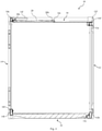
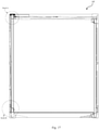
- Figs. 1 to 12 of the accompanying drawings show a first embodiment of a collapsible intermodal container 10.
- the container 10 comprises a right side wall 12 and a left side wall 14.
- the side walls 12, 14 oppose each other and are substantially parallel to each other.
- Each of the side walls 12, 14 is formed from a rectangular corrugated steel panel which is surrounded by a rectangular steel frame.
- the right side wall 12 is defined by an upper longitudinal end 12a, a lower longitudinal end 12b, a front end 12c and a rear end 12d.
- the left side wall 14 is defined by an upper longitudinal end 14a, a lower longitudinal end 14b, a front end 14c and a rear end 14d.
- the right side wall 12 has a lower flange 12e which is disposed at the lower longitudinal end 12b and extends towards the lower longitudinal end 14b of the left side wall 14.
- the right side wall 12 further has three stop members 12f that are disposed at the upper longitudinal end 12a and are evenly spaced apart between the front end 12c and the rear end 12d.
- Each of the stop members 12f is formed from a steel channel and extends in an upward direction.
- the right side wall 12 further has eight pin-like protrusions 12g. Four of the protrusions 12g are disposed at the front end 12c and are evenly spaced apart between the longitudinal ends 12a, 12b.
- the other four protrusions 12g are disposed at the rear end 12d and are evenly spaced apart between the longitudinal ends 12a, 12b. Each of the protrusions 12g extends in a rightward (i.e. an outward) direction.
- the right side wall 12 further includes three round steel rods 12h disposed at the lower longitudinal end 12b and evenly spaced apart between the front end 12c and the rear end 12d. Each of the rods 12h extends substantially horizontally in a leftward direction towards the lower longitudinal end 14b of the left side wall 14.
- the right side wall 12 further has four engagement members in the form of four steel corner plates 12i. Two corner plates 12i are disposed at the front end 12c and extend in a forward direction. The other two plates 12i are disposed at the rear end 12d and extend in a rearward direction.
- the left side wall 14 has an upper flange 14e which is disposed at the upper longitudinal end 14a and extends towards the upper longitudinal end 12a of the right side wall 12.
- the left side wall 14 further includes three round steel rods 14f that are disposed at the upper longitudinal end 14a and slightly above the upper flange 14e.
- the rods 14f are evenly spaced apart between the front end 14c and the rear end 14d.
- Each of the steel rods 14f extends substantially horizontally in a rightward direction towards and substantially aligned with a respective stop member 12f.
- the left side wall 14 further has four engagement members in the form of four steel corner plates 14g. Two corner plates 14g are disposed at the front end 14c and extend in a forward direction. The other two plates 14g are disposed at the rear end 14d and extend in a rearward direction.
- the container 10 further comprises an upper wall 16 located between the right side wall 12 and the left side wall 14.
- the upper wall 16 is fabricated from a rectangular corrugated steel panel.
- the upper wall 16 is defined by a right longitudinal end 16a, a left longitudinal end 16b, a front end 16c and a rear end 16d.
- the left longitudinal end 16b is engageable with the upper flange 14e of the left side wall 14 for removable attachment (e.g., by screws and/or bolts).
- the upper wall 16 has eight lugs 16e disposed on the upper surface of the upper wall 16. The lugs 16e are evenly spaced apart between the front end 16c and the rear end 16d, and each lug 16e extends upwardly from the upper surface of the upper wall 16.
- the upper wall 16 further has a right flange 16f disposed at the right longitudinal end 16a.
- the right flange 16f is hingedly attached to the upper longitudinal end 12a of the right side wall 12 such that the upper wall 16 is able to pivot in relation to the right side wall 12 via that hinged connection.
- the pivotal motion of the upper wall 16 is limited to about 90 degrees in relation to the right side wall 12.
- the container 10 further comprises a lower wall 18 located between the right side wall 12 and the left side wall 14.
- the lower wall 18 is fabricated from steel and is substantially rectangular in shape.
- the lower wall 18 is defined by a right longitudinal end 18a, a left longitudinal end 18b, a front end 18c and a rear end 18d.
- the right longitudinal end 18a is engageable with the lower flange 12e of the right side wall 12 for removable attachment (e.g., by screws and/or bolts).
- the lower wall 18 has eight lugs 18e disposed on the lower surface of the lower wall 18.
- the lugs 18e are evenly spaced apart between the front end 18c and the rear end 18d, and each lug 18e extends downwardly from the lower surface of the lower wall 18.
- the left longitudinal end 18b has a left flange 18f hingedly attached to the lower longitudinal end 14b of the left side wall 14 such that the lower wall 18 is able to pivot in relation to the left side wall 14 via that hinged connection.
- the pivotal motion of the lower wall 18 is limited to about 90 degrees in relation to the left side wall 14.
- the container 10 further comprises eight upper link members 20 and eight lower link members 22.
- Each of the upper and lower link members 20, 22 is elongate and formed from steel.
- Each upper link member 20 has a first end 20a hingedly attached to the upper flange 14e and a second end 20b hingedly attached to a respective lug 16e of the upper wall 16 such that the upper link members 20 are able to pivot in relation to the left side wall 14.
- Each lower link member 22 has a first end 22a hingedly attached to the lower flange 12e and a second end 22b hingedly attached to a respective lug 18e of the lower wall 18 such that the lower link members 22 are able to pivot in relation to the right side wall 12.
- the container 10 further comprises a front end assembly 24 and a rear end assembly 26, the front and rear end assemblies 24, 26 being designed for closing the front and rear ends of the container 10 in the erected configuration and for controlling access to the interior of the container 10.
- the end assemblies 24, 26 include door panels for accessing the interior of the container 10 in the erected configuration.
- the front and rear end assemblies 24, 26 are also referred to herein as front and rear door assemblies 24, 26.
- An end assembly of the collapsible intermodal container 10 not having any door will typically simply include an end wall supported within a peripheral rigid frame.
- the front door assembly 24 comprises a rectangular peripheral rigid frame which is formed from steel and defines a doorway.
- the rigid frame of the front door assembly 24 has a right upright member 24a, a left upright member 24b, an upper cross-bar member 24c and a lower cross-bar member 24d.
- a corner casting 25 for engagement with twistlocks and/or bridge clamps.
- the left member 24b is hingedly attached to the front end 14c of the left side wall 14 such that the front door assembly 24 is able to pivot in relation to the left side wall 14.
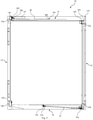
- the front door assembly 24 is able to pivot from a closed position in which the front door assembly 24 extends substantially perpendicularly from the left side wall 14 (see Fig. 1 ) and an open position in which the front door assembly 24 extends substantially parallel and adjacent the left side wall 14 (see Fig. 2 ).
- the front door assembly 24 further comprises a right door panel 24e hingedly attached to the right member 24a and a left door panel 24f hingedly attached to the left member 24b such that the door panels 24e, 24f are able to open and close the doorway in a similar manner to French doors.
- the front door assembly 24 further comprises a flap member 24g in the form of an elongate planar steel piece.
- the flap member 24g is hingedly attached to the right member 24a along one of its longitudinal sides such that flap member 24g is able to pivot in relation to the right member 24a.
- the flap member 24g has four openings 24h that are evenly spaced apart along its length and each opening 24h is adapted to receive a respective protrusion 12g on the front end 12c for removable attachment of the right member 24a of the front door assembly 24 to the front end 12c of the right side wall 12.
- the front door assembly 24 further comprises four corner brackets 24z disposed at each corner. As best seen in Fig. 1a , each corner bracket 24z defines an opening for slidingly receiving a respective corner plate 12i, 14g on the front ends 12c, 14c such that the respective corner plate 12i, 14g abuts with an adjacent corner casting 25 when received.
- the front door assembly 24 and the rear door assembly 26 are substantially identical, only the front door assembly 24 is described above in detail.
- the rear door assembly 26 operates in substantially the same manner and comprises substantially identical components to those described above.
- the left member is hingedly attached to the rear end 14d of the left side wall 14 and the openings of the flap member of the rear door assembly 26 are adapted to respectively receive the protrusions 12g on the rear end 12d for removable attachment of the right member of the rear door assembly 26 to the rear end 12d of the right side wall 12.
- the openings defined by the corner brackets are adapted to respectively receive the corner plates 12i, 14g on the rear ends 12d, 14d.
- the container 10 is configurable between an erected configuration and a collapsed configuration.
- the upper wall 16 extends from the upper longitudinal end 12a of the right side wall 12 to the upper longitudinal end 14a of the left side wall 14 such that the upper wall 16 is substantially perpendicular to the right and left side walls 12, 14.
- the left longitudinal end 16b abuts and engages the upper flange 14e of the left side wall 14.
- the upper link members 20 are located above the upper wall 16.
- the lower wall 18 extends from the lower longitudinal end 14b of the left side wall 14 to the lower longitudinal end 12b of the right side wall 12 such that the lower wall 18 is substantially perpendicular to the right and left side walls 12, 14.
- the right longitudinal end 18a abuts and engages the lower flange 12e of the right side wall 12.
- the lower link members 22 are below the lower wall 18.
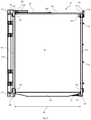
- the upper wall 16 is spaced apart from the lower wall 18 and the upper wall 16 extends parallel to the lower wall 18 such that an inner surface of the upper wall 16 is generally parallel to an inner surface of the lower wall 18. Accordingly, as best shown in Fig. 6 , the right side wall 12 and the left side wall 14 are spaced apart by a first normal distance D1 of about 221 centimetres to define an interior 28 for storing goods.
- the first normal distance D1 i.e., the width of the interior 28
- ISO International Standard Organization
- the first normal distance D1 may be between 201 centimetres to 226 centimetres.
- the door assemblies 24, 26 are in the closed position with the rigid frame of the front door assembly 24 abutting the front ends 12c, 14c, 16c, 18c and the rigid frame of the rear door assembly 26 abutting with the rear ends 12d, 14d, 16d, 18d to enclose the interior 28.
- the openings of the flap members of the door assemblies 24, 26 receive the respective protrusions 12g for removable attachment. It will be appreciated that, once received, the protrusions 12g may be fixed to the flap members of the door assembles 24, 26 by bolting or any other means.
- the openings defined by the corner brackets of the door assemblies 24, 26 receive the corner plates 12i, 14g such that the corner plates 12i, 14g abut with respective adjacent corner castings 25.
- This locates the front and rear door assemblies 24, 26 with respect to the side walls 12, 14 in the erected configuration and allows the walls 12, 14, 16, 18 to be supported by the rigid frames of the door assemblies 24, 26 such that the weight of the walls 12, 14, 16, 18 is transferred to the door assemblies 24, 26.
- This also allows the rigid frames of the door assemblies 24, 26 to lock the container 10 in the erected configuration by limiting movement between the right and left side walls 12, 14 and to provide the container 10 in the erected configuration with sufficient structural strength and rigidity.
- the structural strength of the container 10 in the erected configuration meets the requirements outlined by ISO in relation to standardised intermodal containers. It will be appreciated that access to the interior 28 can be controlled by opening and closing the door panels of each door assembly 24, 26.
- the protrusions 12g are removed from the openings of the flaps of the door assemblies 24, 26 by pivoting the flaps of the door assemblies 24, 26 away from the right wall 12.
- the corner plates 12i, 14g are then slidingly removed from the openings defined by the brackets of the door assemblies 24, 26 as the door assemblies 24, 26 are pivoted to the open positions (see Figs. 2 , 3 and 6 ).
- the upper wall 16 pivots towards the right side wall 12
- the lower wall 18 pivots towards the left side wall 14.
- the right side wall 12 will be prevented from further moving towards the left side wall 14 and the container 10 will be in the collapsed configuration.
- the upper wall 16 extends downwardly from the upper longitudinal end 12a of the right side wall 12.
- the upper link members 20 extend downwardly from the upper flange 14e and are located between the left side wall 14 and the upper wall 16.
- the lower wall 18 extends upwardly from the lower longitudinal end 14b of the left side wall 14.
- the lower link members 22 extend upwardly from the lower flange 12e of the right side wall 12 and are located between the right side wall 12 and the lower wall 18.
- the upper wall 16 is adjacent to, or abutted with, the lower wall 18.
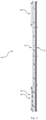
- the upper wall 16 extends substantially parallel to the lower wall 18 such that the inner surface of the upper wall 16 is substantially parallel to the inner surface of the lower wall 18. Accordingly, the right side wall 12 and the left side wall 14 are spaced apart by a second normal distance D2 of about 33 centimetres, which is less than the first normal distance D1.
- the second normal distance D2 may be between 23 centimetres and 98 centimetres.
- the container 10 is configured from the erected configuration to the collapsed configuration by manually moving the door assemblies 24, 26 to the open positions. Then, the right wall 12 is fixed relative to a stationary structure and the left wall 14 is moved towards the right wall 12 by an actuator, such as a hydraulic actuator, until the steel rods 14f abut with the stopping members 12f and the steel rods 12h abut with the lower longitudinal end 14b of the left side wall 14. To reverse this process (i.e., configure the container 10 from the collapsed configuration to the erected configuration), the right wall 12 is again fixed to the stationary structure and the left wall 14 is moved from the right wall 12 by the actuator until the link members 20, 22 prevent further movement of the left wall 14.
- an actuator such as a hydraulic actuator
- the container 10 in the erected configuration meets the specifications required by ISO, specifically ISO 1496-1:2013 - Series 1 Freight Containers, and therefore can be readily used with existing transportation infrastructure. Further, when the container 10 configures from the erected configuration to the collapsed configuration, the container 10 is able to significantly reduce its width. This allows a greater number of empty containers 10 to be transported in a single shipment compared to standard intermodal containers. Also, this allows a greater number of containers 10 to be stored in a defined area compared to standard containers. Furthermore, the container 10 can be readily configured between the erected configuration and the collapsed configuration without the need for assembly and/or removal of parts.
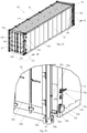
- Figs. 13 to 21 of the accompanying drawings show a second embodiment of a collapsible intermodal container 10'.
- Features of the collapsible intermodal container 10' that are substantially identical or similar to those of the collapsible intermodal container 10 are provided with the same reference numerals.
- the collapsible intermodal container 10' is substantially identical to the collapsible intermodal container 10. However, as best seen in Fig. 13 , the collapsible intermodal container 10' further comprises four lifting systems 30a, 30b, 30c, 30d for use in configuring the container 10' to the erected configuration.
- Each of the lifting systems 30a, 30b, 30c, 30d includes an elongate flexible strap 32 for use in lifting the upper wall 16 into position when configuring the container 10' to the erected configuration.
- the lifting systems 30a, 30b, 30c, 30d are also referred to herein as strap systems 30a, 30b, 30c, 30d, and one of these strap systems 30a will now be described in greater detail.
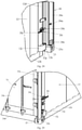
- the strap system 30a comprises a strap 32 with one end 34 attached to the left longitudinal end 16b of the upper wall 16 (see Fig. 18 ) and another end 36 attached to a foot hold 38 (see Fig. 19 ).
- the foot hold 38 is in the form of a steel frame with a shoulder portion 40 and an aperture 42.
- the strap system 30a further comprises a roller mechanism 44 having a body 46 attached to the upper longitudinal end 14a and a pair of opposing rollers 48, 50 rotatably attached to the body 46 such that the roller 48 is located on the outside of the left wall 14 and the roller 50 is located on the inside of the left wall 14.
- the strap 32 is threaded through the body 46 of the roller mechanism 44 and engaged with the rollers 48, 50 such that upward or downward movement of one of the ends 34, 36 of the strap 32 causes an opposite movement at the other end 34, 36.
- the strap system 30a further comprises a bracket 52 attached to the outside of the left wall 14 at or near the lower longitudinal end 14b.
- the bracket 52 has a pair of protruding members 53.
- Each of the protruding members 53 has an upwardly extending recess to receive a portion of the foot hold 38 for securement therewith.
- the strap system 30a further comprises a pair of guide rails 54 attached to the outside of the left wall 14.
- the guide rails 54 extend from the upper longitudinal end 14a to the bracket 52.
- Each guide rail 54 defines a channel which receives a portion of the foot hold 38 such that the foot hold 38 is able to slide upwardly and downwardly along the guide rails 54. It will be appreciated, however, that the guide rails 54 limit the sideward movement of the foot hold 38.
- the container 10' is configured to the collapsed configuration.
- the strap 32 causes the foot hold 38 to be located near the upper longitudinal end 14a of the left wall 14.
- the foot hold 38 is slidingly moved downwards along the guide rails 54 by a user. This causes the strap 32 to pull the left longitudinal end 16b in an upward direction as best seen in Fig. 20 .
- the foot hold 38 is near the bracket 52, the user stands on the shoulder portion 40 of the foot hold 38 to force the container 10' into the erected configuration.
- the foot hold 38 is manipulated such that the pair of protruding members 53 extend through the aperture 42 of the foot hold 38 such that the recesses of the protruding members 53 receive portions of the foot hold 38. This effectively locks the container 10' in the erected configuration.
- the user in order to unlock the container 10' from the erected configuration, the user will stand on the shoulder portion 40 of the foot hold 38 to remove portions of the foot hold 38 from the recesses of the protruding members 53. Then, the user will manipulate the foot hold 38 so that the protruding member 53 are removed from the aperture 42 and the foot hold 38 is free to slide upwardly along the guide rails 54. This will allow the container 10' to configure to the collapsed configuration.
- each of the strap system 30a, 30b, 30c, 30d are substantially identical, only the strap system 30a is described above in detail.
- the other strap systems 30b, 30c, 30d operate in substantially the same manner and comprises substantially identical components to those described above.
- Figs. 22 to 25 of the accompanying drawings show a third embodiment of a collapsible intermodal container 10".
- the features of the collapsible intermodal container 10" that are substantially identical or correspond to those of the collapsible intermodal containers 10, 10' of the first and second embodiments are provided with the same reference numerals and will not be described further.
- this third embodiment of a collapsible intermodal container 10" differs in relation to the closure mechanism for locating and securing the front and rear door assemblies 24, 26 in the closed position when the collapsible intermodal container 10" is being configured to the erected configuration.
- the closure mechanism instead of a closure mechanism comprising a flap member 24g hingedly attached to the right upright member 24a of the front door assembly 24, with openings 24h adapted to receive respective protrusions 12g on the front end 12c of the right side wall 12, the closure mechanism comprises two closure levers 24i fixed to the front end 12c of the right side wall 12, spaced apart as upper and lower closure levers 24i.
- Each closure lever 24i has a handle 24j that is operable to extend a latch ann 24k for engaging a catch 24m that is fixed to the upright member 24a of the front door assembly 24 and aligned with the latch arm 24k.
- the handle 24j is further operable to retract the latch arm 24k as it engages the catch 24m to draw the front door assembly 24 into the closed position.
- An inner side of the door frame members 24a, 24b, 24c, 24d may include a flexible seal or gasket, such as a rubber bead, to cushion and seal the front door assembly 24 against the front ends of the walls 12, 14. 16, 18 in the closed position shown in Fig. 25 .
- each closure lever 26i has a handle 26j that operates to extend a latch ann 26k to engage a catch 26m that is fixed to the upright 26a of the rear door assembly 26 and aligned with the latch arm 26k.
- the handle 26j is operable to retract the latch arm 26k when it engages the catch 26m to draw the rear door assembly 26 into the closed position.
- the intermodal container 10" of this embodiment includes engagement members formed as forwardly and rearwardly extending corner block members 12j that present a tapered end face 12k to matingly engage with or be received by complementary corner elements 24n, 26n of the front and rear door assemblies, respectively.
- the respective corner block members 12j cooperate with the corner elements 24n, 26n to locate the door assemblies 24, 26 correctly with respect to the side wall 12 as the door assemblies 24, 26 are moved into the closed position.
- the corner block members 12j abut with an adjacent corner casting 25 and allow the walls 12, 14, 16, 18 to be at least partly supported by the rigid frames of the door assemblies 24, 26.
- the forwardly and rearwardly extending corner block members 12j include a steel pin 12p that is captured but movable within a bore through those block members 12j.
- the pin 12p may be driven (e.g. with a hammer) through the block 12j to project into a corresponding hole 25o provided in the corner casting 25. Accordingly, in addition to the closure levers 24i, 26i, the pins 12p operate to fix and lock the front and rear door assemblies 24, 26 in their closed positions.
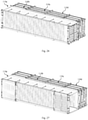
- Figs. 26 to 33 of the accompanying drawings show four collapsible intermodal containers 110a, 110b, 110c, 110d assembling together to form an embodiment of a collapsible intermodal container assembly 100 as shown in Figs. 31 to 33 .
- each of the four collapsible intermodal containers 110a, 110b, 110c, 110d is identical to the collapsible intermodal container 10 described above. Accordingly, features of the collapsible intermodal containers 110a, 110b, 110c, 110d that are identical to those of the collapsible intermodal container 10 are provided with the same reference numerals.
- the door assemblies 24, 26 of the container 110d are moved to the open positions.
- the right wall 12 of the container 110d is then fixed relative to a stationary structure (not shown) and the left wall 14 of the container 110d is moved towards the right wall 12 of the container 110d until the container 110d is configured to the collapsed configuration.
- the right wall 12 of the container 110c is abutted against the door assemblies 24, 26 of the container 110d.
- the door assemblies 24, 26 of the container 110c are moved to the open positions.
- the left wall 14 of the container 110c is moved towards the right wall 12 of the container 110c until the container 110c is configured to the collapsed configuration.
- the right wall 12 of the container 110b is abutted against the door assemblies 24, 26 of the container 110c.
- the door assemblies 24, 26 of the container 110b are moved to the open positions.
- the left wall 14 of the container 110b is moved towards the right wall 12 of the container 110b until the container 110b is configured to the collapsed configuration.
- a fourth step as best seen in Fig. 26 , the right wall 12 of the container 110a is abutted against the door assemblies 24, 26 of the container 110b.
- the door assemblies 24, 26 of the container 110a are moved to the open positions.
- the right wall 12 of the container 110d remains fixed relative to the stationary structure, as best seen in Figs. 24 and 25 , the left wall 14 of the container 110a is moved towards the right wall 12 of the container 110a until the container is configured to the collapsed configuration.
- the containers 110a, 110b, 110c, 110d are now in a sidewardly stacked formation.
- a fifth step as best seen in Figs. 30 to 33 , the door assemblies 24, 26 of the container 110a are moved to the closed positions such that at least the front ends 12c, 14c of the containers 110a, 110b, 110c, 110d abut with the rigid frame of the front door assembly 24 of the container 110a and the rear ends 12d, 14d of the containers 110a, 110b, 110c, 110d abut with the rigid frame of the rear door assembly 26 of the container 110a. It will be appreciated that the door assemblies 24, 26 of the container 110a in the closed positions will substantially limit forward and rearward movement of the containers 110a, 110b, 110c, 110. Further, as best seen in Figs.
- the openings defined by the corner brackets of the door assemblies 24, 26 of the container 110a receive the corner plates 14g of the container 110a and the corner plates 12i of the container 110d such that the corner plates 14g of the container 110a and the corner plates 12i of the container 110d abut with respective adjacent corner castings 25 of the door assemblies 24, 26 of the container 110a.
- the openings of the flap members of the door assemblies 24, 26 of the container 110a receive the protrusions 12g of the container 110d for removable attachment such that the door assemblies 24, 26 of the container 110a are locked in the closed positions. As best seen in Figs.
- the corner plates 12i of the container 110a and the corner plates 14g of the container 110d abut with the upper and lower members of the rigid frames of the door assemblies 24, 26 such that the right wall 12 of the container 110a and the left wall 14 of the container 110d are located between the door assemblies 24, 26 of the container 110a and limited in relative vertical movement.
- the corner plates 12i, 14g of the containers 110b, 110c abut with the upper and lower members of the rigid frames of the door assemblies 24, 26 of the container 110a such that the containers 110b, 110c are located between the door assemblies 24, 26 of the container 110a and limited in relative vertical movement.
- the assembly 100 has the same periphery as the container 10 in the erected configuration and the structural strength of the assembly 100 meets the requirements outlined by ISO in relation to a standardised intermodal container. Also, it will be appreciated that left wall 14 of the container 110a and the right wall 12 of the container 110d are spaced apart by an assembled distance which is the same as the first normal distance D1 of the container 10 described above.
- the assembly 100 meets the specifications required by ISO, specifically ISO 1496-1:2013 - Series 1 Freight Containers, and therefore can be readily used with existing transportation infrastructure. Further, the assembly 100 allows up to four empty containers 110a, 110b, 110c, 110d to be transported in the same periphery as a single container.
Claims (14)
- Conteneur intermodal repliable (10), comprenant :des première et seconde parois latérales parallèles opposées (12, 14), la première paroi latérale (14) étant reliée à la seconde paroi latérale (12) de sorte que le conteneur intermodal repliable (10) est configurable entre une configuration déployée dans laquelle les première et seconde parois latérales (12, 14) sont espacées d'une première distance (D1) pour définir un intérieur (28) pour stocker des biens, et une configuration repliée dans laquelle les première et seconde parois latérales (12, 14) sont espacées d'une seconde distance (D2) qui est inférieure à la première distance (D1) ; etdes ensembles d'extrémité avant et arrière (24, 26) pour fermer des extrémités avant et arrière du conteneur (10) dans la configuration déployée et pour commander l'accès à l'intérieur (28), chacun des ensembles d'extrémité avant et arrière (24, 26) étant fixé de manière articulée à la première paroi latérale (14),dans lequel, lorsque le conteneur intermodal repliable (10) est dans la configuration déployée, les ensembles d'extrémité avant et arrière (24, 26) peuvent venir en prise avec la seconde paroi latérale (12) pour fixer la première paroi latérale (14) par rapport à la seconde paroi latérale (12), et, lorsque le conteneur intermodal repliable est dans la configuration repliée, les ensembles d'extrémité avant et arrière (24, 26) peuvent venir en prise avec au moins un autre conteneur intermodal repliable (10') pour fixer la première paroi latérale (14) par rapport à l'autre conteneur intermodal repliable (10'),caractérisé en ce que chacun des ensembles d'extrémité avant et arrière (24, 26) peut pivoter entre :une position fermée dans laquelle l'ensemble d'extrémité respectif (24, 26) s'étend sensiblement perpendiculairement depuis la première paroi latérale (14), etune position ouverte dans laquelle l'ensemble d'extrémité respectif (24, 26) s'étend sensiblement parallèlement et de manière adjacente à un côté externe de la première paroi latérale (14).
- Conteneur intermodal repliable selon la revendication 1, dans lequel, lorsque le conteneur intermodal repliable (10) est dans la configuration repliée, les ensembles d'extrémité avant et arrière (24, 26) peuvent en outre venir en prise avec la seconde paroi latérale (12) pour placer la seconde paroi latérale (12) entre les ensembles d'extrémité avant et arrière (24, 26).
- Conteneur intermodal repliable selon la revendication 1 ou 2, dans lequel chacune des première et seconde parois latérales (12, 14) comprend :des éléments s'étendant vers l'avant supérieurs et inférieurs (12j) ; etdes éléments s'étendant vers l'arrière supérieurs et inférieurs (12j),dans lequel les éléments s'étendant vers l'avant supérieurs et inférieurs (12j) des première et seconde parois latérales (12, 14) sont conçus pour venir en prise avec l'ensemble d'extrémité avant (24) et les éléments s'étendant vers l'arrière supérieurs et inférieurs (12j) des première et seconde parois latérales (12, 14) sont conçus pour venir en prise avec l'ensemble d'extrémité arrière (26) de sorte que les première et seconde parois latérales (12, 14) sont sensiblement supportées par les ensembles d'extrémité avant et arrière (24, 26).
- Conteneur intermodal repliable selon la revendication 3, dans lequel chacun des ensembles d'extrémité avant et arrière (24, 26) comprend de préférence un volet rigide (24g, 26g) fixé de manière articulée à un second montant latéral (24a, 26a) et pouvant pivoter pour se fixer à la seconde paroi latérale (12), et dans lequel chacun des ensembles avant et arrière (24, 26) comprend un cadre rigide périphérique comprenant :des premiers et seconds montants latéraux (24a, 24b, 26a, 26b), chacun des premiers et seconds montants latéraux (24a, 24b, 26a, 26b) ayant des extrémités supérieures et inférieures ;quatre parties d'angle, de préférence une moulure d'angle (25) pour une mise en prise de verrou tournant et/ou de collier à pont, respectivement montées sur les extrémités des premiers et secondes montants latéraux (24a, 24b, 26a, 26b) ; etdes traverses supérieures et inférieures (24c, 24d, 26c, 26d), la traverse supérieure (24c, 26c) s'étendant depuis la partie d'angle (25) montée sur l'extrémité supérieure du premier montant latéral (24b, 26b) vers la partie d'angle (25) montée sur l'extrémité supérieure du second montant latéral (24a, 26b), et la traverse inférieure (24d, 26d) s'étendant depuis la partie d'angle (25) montée sur l'extrémité inférieure du premier montant latéral (24b, 26b) vers la partie d'angle (25) montée sur l'extrémité inférieure du second montant latéral (24a, 26a).
- Conteneur intermodal replié selon la revendication 4, dans lequel, lorsque les éléments s'étendant vers l'avant supérieurs et inférieurs (12j) des première et seconde parois latérales (12, 14) viennent en prise avec l'ensemble d'extrémité avant (24), chacun des éléments s'étendant vers l'avant supérieurs (12j) vient en butée avec l'une des parties d'angle (25) montées sur les extrémités supérieures des premier et second montants latéraux (24a, 24b) de l'ensemble d'extrémité avant (24) ou la traverse supérieure (24c) de l'ensemble d'extrémité avant (24) et chacun des éléments s'étendant vers l'avant inférieurs (12j) vient en butée avec l'une des parties d'angle (25) montées sur les extrémités inférieures des premier et second montants latéraux (24a, 24b) de l'ensemble d'extrémité avant (24) ou la traverse inférieure (24d) de l'ensemble d'extrémité avant (24).
- Conteneur intermodal repliable selon la revendication 4 ou 5, dans lequel, lorsque les éléments s'étendant vers l'arrière supérieurs et inférieurs (12j) des première et seconde parois latérales (12, 14) viennent en prise avec l'ensemble d'extrémité arrière (26), chacun des éléments s'étendant vers l'arrière supérieurs (12j) vient en butée avec l'une des parties d'angle (25) montées sur les extrémités supérieures des premier et second montants latéraux (26a, 26b) de l'ensemble d'extrémité arrière (26) ou la traverse supérieure (26c) de l'ensemble d'extrémité arrière (26) et chacun des éléments s'étendant vers l'arrière inférieurs (12j) vient en butée avec l'une des parties d'angle (25) montées sur les extrémités inférieures des premier et second montants latéraux (26a, 26b) de l'ensemble d'extrémité arrière (26) ou la traverse inférieure (26d) de l'ensemble d'extrémité arrière (26) .
- Conteneur intermodal repliable selon l'une quelconque des revendications 1 à 6, comprenant en outre un ou plusieurs système de levage, de préférence une pluralité des systèmes de levage (30a, 30b, 30c, 30d) agencés de manière espacée sur une longueur de la première paroi latérale (14), pour une utilisation dans la configuration du conteneur (10) dans la configuration déployée, chaque système de levage (30a, 30b, 30c, 30d) comprenant une ligne allongée ou un élément de tension (32) pour une utilisation dans le levage d'une paroi supérieure (16) du conteneur (10) lors de la configuration du conteneur (10) dans la configuration déployée.
- Conteneur intermodal repliable selon la revendication 7, dans lequel chaque système de levage (30a, 30b, 30c, 30d) comprend en outre un mécanisme à rouleau (44) pour supporter le déplacement de la ligne flexible ou de l'élément de tension (32) lorsqu'il est attiré ou tiré, et un élément de maintien (38) pour permettre à un opérateur de maintenir et de tirer la ligne allongée ou l'élément de tension (32) ;dans lequel une région d'extrémité de la ligne allongée ou de l'élément de tension (32) est attachée ou fixée à une région de bord libre de la paroi supérieure (16), à partir de laquelle la ligne allongée ou l'élément de tension (32) s'étend pour passer à travers ou sur le mécanisme à rouleau (44) vers un côté externe de l'autre paroi latérale (12), etdans lequel l'élément de maintien (38) est fixé à une région d'extrémité opposée de la ligne allongée ou de l'élément de tension (32) pour permettre à un opérateur de maintenir et de tirer la ligne allongée ou l'élément de tension (32) à travers ou sur le mécanisme à rouleau (44) pour lever la région de bord libre de la paroi supérieure (16) lorsque le conteneur (10) est configuré dans la configuration déployée, etdans lequel chaque système de levage (30a, 30b, 30c, 30d) comporte de préférence une piste ou un rail (54) fixé au côté externe de la première paroi latérale (14) pour guider le mouvement de l'élément de maintien (38) lorsque le conteneur intermodal repliable (10) est configuré dans la configuration déployée.
- Conteneur intermodal repliable selon la revendication 7 ou 8, dans lequel chaque système de levage (30a, 30b, 30c, 30d) comporte un support (52) fixé au côté externe de la première paroi latérale (14) au niveau ou près de l'extrémité inférieure de la première paroi latérale (14) à laquelle l'élément de maintien (38) est fixé ou attaché lorsque le conteneur intermodal (10) est dans la configuration déployée.
- Ensemble conteneur intermodal repliable, comprenant :des premier et deuxième conteneurs intermodaux repliables (110a, 110b) selon l'une quelconque des revendications 1 à 9, chacun des premier et deuxième conteneurs intermodaux repliables (110a, 110b) étant dans la configuration repliée,dans lequel les ensembles d'extrémité avant et arrière (24, 26) du premier conteneur intermodal repliable (110a) viennent en prise avec la première paroi latéral (14) du premier conteneur intermodal repliable (110a) et la seconde paroi latérale (12) du deuxième conteneur intermodal repliable (110b) de sorte que la première paroi latéral (14) du premier conteneur intermodal repliable (110a) est fixée à la seconde paroi latérale (12) du deuxième conteneur intermodal repliable (112b), et de préférence comprenant en outre des troisième et quatrième conteneurs intermodaux repliables (110c, 110d) selon l'une quelconque des revendications 1 à 9,dans lequel chacun des troisième et quatrième conteneurs intermodaux repliables (110c, 110d) sont dans la configuration repliée,dans lequel chacun des ensembles d'extrémité avant et arrière (24, 26) du troisième conteneur intermodal repliable (110c) s'étend sensiblement parallèlement et de manière adjacente à la première paroi latérale (14) du troisième conteneur intermodal repliable (110c) et chacun des ensembles d'extrémité avant et arrière (24, 26) du quatrième conteneur intermodal repliable (110d) s'étend sensiblement parallèlement et de manière adjacente à la première paroi latérale (14) du quatrième conteneur intermodal repliable (110d), etdans lequel les ensembles d'extrémité avant et arrière (24, 26) du premier conteneur intermodal repliable (110a) viennent en prise avec les troisième et quatrième conteneurs intermodaux repliables (110c, 110d) de sorte que les troisième et quatrième conteneurs intermodaux repliables (110c, 110d) sont placés entre les ensembles d'extrémité avant et arrière (24, 26) du premier conteneur intermodal repliable (110a) et sensiblement supportés par ceux-ci.
- Ensemble conteneur intermodal repliable selon la revendication 10, dans lequel les ensembles d'extrémité avant et arrière (24, 26) du premier conteneur intermodal repliable (110a) s'étendent sensiblement perpendiculairement depuis la première paroi latérale (14) du premier conteneur intermodal repliable (110a) vers la seconde paroi latérale (12) du deuxième conteneur intermodal repliable (110b), et dans lequel les ensembles d'extrémité avant et arrière (24, 26) du deuxième conteneur intermodal repliable (110b) s'étendent sensiblement parallèlement et de manière adjacente à la première paroi latérale (14) du deuxième conteneur intermodal repliable (110b) et sont situés entre les ensembles d'extrémité avant et arrière (24, 26) du premier conteneur intermodal repliable (110a).
- Ensemble conteneur intermodal repliable selon la revendication 10 ou 11, dans lequel les ensembles d'extrémité avant et arrière (24, 26) viennent en outre en prise avec la seconde paroi latérale (12) du premier conteneur intermodal repliable (110a) et la première paroi latérale (14) du deuxième conteneur intermodal repliable (110b) de sorte que la seconde paroi latérale (12) du premier conteneur intermodal repliable (110a) et la première paroi latérale (14) du deuxième conteneur intermodal repliable (110b) sont situées entre les ensembles d'extrémité avant et arrière (24, 26) du premier conteneur intermodal repliable (110a).
- Ensemble conteneur intermodal repliable selon la revendication 10, lorsqu'il comprend les troisième et quatrième conteneurs intermodaux repliables (110c, 110d), dans lequel les premier, deuxième, troisième et quatrième conteneurs intermodaux repliables (110a, 110b, 110c, 110d) sont dans une formation empilée latéralement de sorte que la seconde paroi latérale (12) du premier conteneur intermodal repliable (110a) vient en butée avec les ensembles d'extrémité avant et arrière (24, 26) du troisième conteneur intermodal repliable (110c), la seconde paroi latérale (12) du troisième conteneur intermodal repliable (110c) vient en butée avec les ensembles d'extrémité avant et arrière (24, 26) du quatrième conteneur intermodal repliable (110d), et la seconde paroi latérale (12) du quatrième conteneur intermodal repliable (110d) vient en butée avec les ensembles d'extrémité avant et arrière (24, 26) du deuxième conteneur intermodal repliable (110b).
- Ensemble conteneur intermodal repliable selon l'une quelconque des revendications 10 à 13, dans lequel une distance assemblée entre la première paroi latérale (14) du premier conteneur intermodal repliable (110a) et la seconde paroi latérale (12) du deuxième conteneur intermodal repliable (110b) est sensiblement égale à la première distance (D1) du premier conteneur intermodal (110a).
Applications Claiming Priority (2)
| Application Number | Priority Date | Filing Date | Title |
|---|---|---|---|
| AU2017900998A AU2017900998A0 (en) | 2017-03-21 | A collapsible intermodal container and a collapsible intermodal container assembly | |
| PCT/AU2017/000276 WO2018170527A1 (fr) | 2017-03-21 | 2017-12-14 | Conteneur intermodal repliable et ensemble conteneur intermodal repliable |
Publications (3)
| Publication Number | Publication Date |
|---|---|
| EP3601105A1 EP3601105A1 (fr) | 2020-02-05 |
| EP3601105A4 EP3601105A4 (fr) | 2021-03-17 |
| EP3601105B1 true EP3601105B1 (fr) | 2022-03-02 |
Family
ID=63583898
Family Applications (1)
| Application Number | Title | Priority Date | Filing Date |
|---|---|---|---|
| EP17902034.2A Active EP3601105B1 (fr) | 2017-03-21 | 2017-12-14 | Conteneur intermodal repliable et ensemble conteneur intermodal repliable |
Country Status (11)
| Country | Link |
|---|---|
| US (1) | US11161686B2 (fr) |
| EP (1) | EP3601105B1 (fr) |
| JP (1) | JP7166262B2 (fr) |
| KR (1) | KR102234744B1 (fr) |
| CN (1) | CN110325459B (fr) |
| AU (1) | AU2017404842B2 (fr) |
| DK (1) | DK3601105T3 (fr) |
| EA (2) | EA201991875A1 (fr) |
| ES (1) | ES2913767T3 (fr) |
| RU (1) | RU2745038C1 (fr) |
| WO (1) | WO2018170527A1 (fr) |
Families Citing this family (2)
| Publication number | Priority date | Publication date | Assignee | Title |
|---|---|---|---|---|
| EP3580147A4 (fr) * | 2017-02-10 | 2020-09-30 | Spectainer Pty Limited | Conteneur intermodal pliable |
| US11621603B2 (en) * | 2020-06-27 | 2023-04-04 | James Michael Wheeler | Portable housing for use with portable electric generators |
Family Cites Families (25)
| Publication number | Priority date | Publication date | Assignee | Title |
|---|---|---|---|---|
| CH453192A (de) * | 1967-04-10 | 1968-06-14 | Algenthia Ag Ges Fuer Entwickl | Quaderförmiger Behälter |
| US3752349A (en) * | 1971-03-15 | 1973-08-14 | Flexogenics Inc | Collapsible container |
| JPH0811877A (ja) * | 1994-06-24 | 1996-01-16 | Masakatsu Shikura | 折りたたみ可能な容器及びその使用方法 |
| JP2002130927A (ja) | 2000-10-20 | 2002-05-09 | Matsushita Refrig Co Ltd | 保冷庫 |
| JP2002264993A (ja) | 2001-03-07 | 2002-09-18 | Pd System:Kk | 輸送用コンテナ |
| GB0226012D0 (en) * | 2002-11-07 | 2002-12-18 | Clive Smith Martin | A car carrying container |
| EP1796990B1 (fr) * | 2004-09-01 | 2011-01-26 | Collapsible Containers Pty Ltd | Grand conteneur démontable à charnières centrales dans les panneaux latéraux |
| US7703632B2 (en) * | 2006-08-04 | 2010-04-27 | Kochanowski George E | Stackable and collapsible container |
| US7823739B2 (en) * | 2006-12-08 | 2010-11-02 | C Cubed I Llc | Collapsible shipping container |
| WO2008104193A1 (fr) * | 2007-02-28 | 2008-09-04 | Texas Oil Capital Holding Corp. | Conteneur pliable |
| CN201140878Y (zh) * | 2007-12-11 | 2008-10-29 | 上海富日商务咨询有限公司 | 一种可折叠式集装箱 |
| US7882973B2 (en) * | 2008-07-30 | 2011-02-08 | Krohn Christopher G | Portable container with integral folding mechanism |
| EP2389328B1 (fr) * | 2009-01-05 | 2015-12-23 | Treck Pty Ltd | Ensemble d'engagement chassis / extrémité pour un conteneur pliable |
| MX2014000807A (es) * | 2011-07-22 | 2015-09-22 | Hankook Pallet Pool Co Ltd | Contenedor plegable. |
| TWI646031B (zh) | 2011-08-15 | 2019-01-01 | 喬治E 寇查諾斯基 | 可逆式可折合貨櫃 |
| CL2011003232A1 (es) * | 2011-12-21 | 2012-07-13 | Claudio De Los Sagrados Corazones Arteaga Reyes | Contenedor plegable que comprende un piso, un panel frontal con puertas de acceso, un panel trasero, un techo, paredes laterales derecha e izquierda, juntas o uniones abisagradas, medios de anclaje laterales, medios para bloquear el abatimiento de los paneles y medios para bloquear o desbloquear el plegado; metodo; uso; sistema. |
| US9193498B2 (en) * | 2012-10-31 | 2015-11-24 | Daiichi Ohmiya Co., Ltd. | Foldable container |
| KR101258612B1 (ko) | 2013-01-10 | 2013-04-26 | 한국컨테이너풀 주식회사 | 접이식 컨테이너 |
| CN203359247U (zh) | 2013-05-31 | 2013-12-25 | 潘国华 | 一种折叠集装箱及其收放吊架组 |
| ES2421059B1 (es) | 2013-06-18 | 2014-03-18 | Miguel Antonio NAVALÓN SIMÓN | Nuevo contenedor plegable |
| US10549908B2 (en) * | 2014-02-20 | 2020-02-04 | George E. Kochanowski | Components and end walls for freight container |
| GB2524326B (en) * | 2014-03-21 | 2017-12-20 | Tim Wong Leung | Novel freight container |
| WO2015199691A1 (fr) * | 2014-06-26 | 2015-12-30 | Heskamp United Collapsable Containers, Llc | Procédé et appareil pour contenant pliable |
| KR101710255B1 (ko) * | 2015-01-19 | 2017-02-27 | 박용재 | 절첩식 컨테이너 |
| EP3580147A4 (fr) * | 2017-02-10 | 2020-09-30 | Spectainer Pty Limited | Conteneur intermodal pliable |
-
2017
- 2017-12-14 CN CN201780087071.1A patent/CN110325459B/zh active Active
- 2017-12-14 EA EA201991875A patent/EA201991875A1/ru unknown
- 2017-12-14 ES ES17902034T patent/ES2913767T3/es active Active
- 2017-12-14 EP EP17902034.2A patent/EP3601105B1/fr active Active
- 2017-12-14 EA EA201992056A patent/EA039688B1/ru unknown
- 2017-12-14 US US16/485,157 patent/US11161686B2/en active Active
- 2017-12-14 KR KR1020197023273A patent/KR102234744B1/ko active IP Right Grant
- 2017-12-14 RU RU2019130905A patent/RU2745038C1/ru active
- 2017-12-14 JP JP2019542730A patent/JP7166262B2/ja active Active
- 2017-12-14 AU AU2017404842A patent/AU2017404842B2/en active Active
- 2017-12-14 WO PCT/AU2017/000276 patent/WO2018170527A1/fr unknown
- 2017-12-14 DK DK17902034.2T patent/DK3601105T3/da active
Also Published As
| Publication number | Publication date |
|---|---|
| EA201991875A1 (ru) | 2020-01-16 |
| EA201992056A1 (ru) | 2020-04-09 |
| EP3601105A4 (fr) | 2021-03-17 |
| KR20190105614A (ko) | 2019-09-17 |
| JP7166262B2 (ja) | 2022-11-07 |
| RU2745038C1 (ru) | 2021-03-18 |
| DK3601105T3 (da) | 2022-05-23 |
| AU2017404842A1 (en) | 2019-01-31 |
| EP3601105A1 (fr) | 2020-02-05 |
| KR102234744B1 (ko) | 2021-04-01 |
| EA039688B1 (ru) | 2022-02-28 |
| US20200071069A1 (en) | 2020-03-05 |
| ES2913767T3 (es) | 2022-06-06 |
| WO2018170527A1 (fr) | 2018-09-27 |
| JP2020511370A (ja) | 2020-04-16 |
| AU2017404842B2 (en) | 2019-03-28 |
| CN110325459B (zh) | 2022-04-19 |
| US11161686B2 (en) | 2021-11-02 |
| CN110325459A (zh) | 2019-10-11 |
Similar Documents
| Publication | Publication Date | Title |
|---|---|---|
| AU2019202968B2 (en) | A collapsible intermodal container | |
| EP2616368B1 (fr) | Conteneur de transport aplatissable | |
| WO2007030535A2 (fr) | Contenant pliable | |
| MX2011003888A (es) | Contenedor de almacenamiento movil plegable. | |
| EP3601105B1 (fr) | Conteneur intermodal repliable et ensemble conteneur intermodal repliable | |
| US11254492B2 (en) | Collapsible intermodal container stacker and a stacking system | |
| EP2686252B1 (fr) | Conteneur de fret | |
| GB2368336A (en) | A freight container | |
| EA040449B1 (ru) | Складной интермодальный контейнер |
Legal Events
| Date | Code | Title | Description |
|---|---|---|---|
| STAA | Information on the status of an ep patent application or granted ep patent |
Free format text: STATUS: THE INTERNATIONAL PUBLICATION HAS BEEN MADE |
|
| PUAI | Public reference made under article 153(3) epc to a published international application that has entered the european phase |
Free format text: ORIGINAL CODE: 0009012 |
|
| STAA | Information on the status of an ep patent application or granted ep patent |
Free format text: STATUS: REQUEST FOR EXAMINATION WAS MADE |
|
| 17P | Request for examination filed |
Effective date: 20190710 |
|
| AK | Designated contracting states |
Kind code of ref document: A1 Designated state(s): AL AT BE BG CH CY CZ DE DK EE ES FI FR GB GR HR HU IE IS IT LI LT LU LV MC MK MT NL NO PL PT RO RS SE SI SK SM TR |
|
| AX | Request for extension of the european patent |
Extension state: BA ME |
|
| RIN1 | Information on inventor provided before grant (corrected) |
Inventor name: PRESS, NICHOLAS OLIVER Inventor name: SALMON, DANIEL GRAHAM Inventor name: HILL, STEPHEN RICHARD Inventor name: TILLER, ROBERT BRUCE Inventor name: HERSHKOVITZ, LIOR |
|
| DAV | Request for validation of the european patent (deleted) | ||
| DAX | Request for extension of the european patent (deleted) | ||
| RAP1 | Party data changed (applicant data changed or rights of an application transferred) |
Owner name: SPECTAINER PTY LIMITED |
|
| REG | Reference to a national code |
Ref country code: HK Ref legal event code: DE Ref document number: 40020488 Country of ref document: HK |
|
| A4 | Supplementary search report drawn up and despatched |
Effective date: 20210212 |
|
| RIC1 | Information provided on ipc code assigned before grant |
Ipc: B65D 88/52 20060101AFI20210208BHEP |
|
| GRAP | Despatch of communication of intention to grant a patent |
Free format text: ORIGINAL CODE: EPIDOSNIGR1 |
|
| STAA | Information on the status of an ep patent application or granted ep patent |
Free format text: STATUS: GRANT OF PATENT IS INTENDED |
|
| INTG | Intention to grant announced |
Effective date: 20211104 |
|
| GRAS | Grant fee paid |
Free format text: ORIGINAL CODE: EPIDOSNIGR3 |
|
| GRAA | (expected) grant |
Free format text: ORIGINAL CODE: 0009210 |
|
| STAA | Information on the status of an ep patent application or granted ep patent |
Free format text: STATUS: THE PATENT HAS BEEN GRANTED |
|
| AK | Designated contracting states |
Kind code of ref document: B1 Designated state(s): AL AT BE BG CH CY CZ DE DK EE ES FI FR GB GR HR HU IE IS IT LI LT LU LV MC MK MT NL NO PL PT RO RS SE SI SK SM TR |
|
| REG | Reference to a national code |
Ref country code: GB Ref legal event code: FG4D |
|
| REG | Reference to a national code |
Ref country code: CH Ref legal event code: EP Ref country code: AT Ref legal event code: REF Ref document number: 1472094 Country of ref document: AT Kind code of ref document: T Effective date: 20220315 |
|
| REG | Reference to a national code |
Ref country code: DE Ref legal event code: R096 Ref document number: 602017054225 Country of ref document: DE |
|
| REG | Reference to a national code |
Ref country code: IE Ref legal event code: FG4D |
|
| REG | Reference to a national code |
Ref country code: DK Ref legal event code: T3 Effective date: 20220519 |
|
| REG | Reference to a national code |
Ref country code: NL Ref legal event code: FP |
|
| REG | Reference to a national code |
Ref country code: ES Ref legal event code: FG2A Ref document number: 2913767 Country of ref document: ES Kind code of ref document: T3 Effective date: 20220606 |
|
| REG | Reference to a national code |
Ref country code: SE Ref legal event code: TRGR |
|
| REG | Reference to a national code |
Ref country code: GR Ref legal event code: EP Ref document number: 20220401020 Country of ref document: GR Effective date: 20220608 |
|
| REG | Reference to a national code |
Ref country code: LT Ref legal event code: MG9D |
|
| PG25 | Lapsed in a contracting state [announced via postgrant information from national office to epo] |
Ref country code: RS Free format text: LAPSE BECAUSE OF FAILURE TO SUBMIT A TRANSLATION OF THE DESCRIPTION OR TO PAY THE FEE WITHIN THE PRESCRIBED TIME-LIMIT Effective date: 20220302 Ref country code: NO Free format text: LAPSE BECAUSE OF FAILURE TO SUBMIT A TRANSLATION OF THE DESCRIPTION OR TO PAY THE FEE WITHIN THE PRESCRIBED TIME-LIMIT Effective date: 20220602 Ref country code: LT Free format text: LAPSE BECAUSE OF FAILURE TO SUBMIT A TRANSLATION OF THE DESCRIPTION OR TO PAY THE FEE WITHIN THE PRESCRIBED TIME-LIMIT Effective date: 20220302 Ref country code: HR Free format text: LAPSE BECAUSE OF FAILURE TO SUBMIT A TRANSLATION OF THE DESCRIPTION OR TO PAY THE FEE WITHIN THE PRESCRIBED TIME-LIMIT Effective date: 20220302 Ref country code: BG Free format text: LAPSE BECAUSE OF FAILURE TO SUBMIT A TRANSLATION OF THE DESCRIPTION OR TO PAY THE FEE WITHIN THE PRESCRIBED TIME-LIMIT Effective date: 20220602 |
|
| REG | Reference to a national code |
Ref country code: AT Ref legal event code: MK05 Ref document number: 1472094 Country of ref document: AT Kind code of ref document: T Effective date: 20220302 |
|
| PG25 | Lapsed in a contracting state [announced via postgrant information from national office to epo] |
Ref country code: PL Free format text: LAPSE BECAUSE OF FAILURE TO SUBMIT A TRANSLATION OF THE DESCRIPTION OR TO PAY THE FEE WITHIN THE PRESCRIBED TIME-LIMIT Effective date: 20220302 Ref country code: LV Free format text: LAPSE BECAUSE OF FAILURE TO SUBMIT A TRANSLATION OF THE DESCRIPTION OR TO PAY THE FEE WITHIN THE PRESCRIBED TIME-LIMIT Effective date: 20220302 Ref country code: FI Free format text: LAPSE BECAUSE OF FAILURE TO SUBMIT A TRANSLATION OF THE DESCRIPTION OR TO PAY THE FEE WITHIN THE PRESCRIBED TIME-LIMIT Effective date: 20220302 |
|
| PG25 | Lapsed in a contracting state [announced via postgrant information from national office to epo] |
Ref country code: SM Free format text: LAPSE BECAUSE OF FAILURE TO SUBMIT A TRANSLATION OF THE DESCRIPTION OR TO PAY THE FEE WITHIN THE PRESCRIBED TIME-LIMIT Effective date: 20220302 Ref country code: SK Free format text: LAPSE BECAUSE OF FAILURE TO SUBMIT A TRANSLATION OF THE DESCRIPTION OR TO PAY THE FEE WITHIN THE PRESCRIBED TIME-LIMIT Effective date: 20220302 Ref country code: RO Free format text: LAPSE BECAUSE OF FAILURE TO SUBMIT A TRANSLATION OF THE DESCRIPTION OR TO PAY THE FEE WITHIN THE PRESCRIBED TIME-LIMIT Effective date: 20220302 Ref country code: PT Free format text: LAPSE BECAUSE OF FAILURE TO SUBMIT A TRANSLATION OF THE DESCRIPTION OR TO PAY THE FEE WITHIN THE PRESCRIBED TIME-LIMIT Effective date: 20220704 Ref country code: EE Free format text: LAPSE BECAUSE OF FAILURE TO SUBMIT A TRANSLATION OF THE DESCRIPTION OR TO PAY THE FEE WITHIN THE PRESCRIBED TIME-LIMIT Effective date: 20220302 Ref country code: CZ Free format text: LAPSE BECAUSE OF FAILURE TO SUBMIT A TRANSLATION OF THE DESCRIPTION OR TO PAY THE FEE WITHIN THE PRESCRIBED TIME-LIMIT Effective date: 20220302 Ref country code: AT Free format text: LAPSE BECAUSE OF FAILURE TO SUBMIT A TRANSLATION OF THE DESCRIPTION OR TO PAY THE FEE WITHIN THE PRESCRIBED TIME-LIMIT Effective date: 20220302 |
|
| PG25 | Lapsed in a contracting state [announced via postgrant information from national office to epo] |
Ref country code: IS Free format text: LAPSE BECAUSE OF FAILURE TO SUBMIT A TRANSLATION OF THE DESCRIPTION OR TO PAY THE FEE WITHIN THE PRESCRIBED TIME-LIMIT Effective date: 20220702 Ref country code: AL Free format text: LAPSE BECAUSE OF FAILURE TO SUBMIT A TRANSLATION OF THE DESCRIPTION OR TO PAY THE FEE WITHIN THE PRESCRIBED TIME-LIMIT Effective date: 20220302 |
|
| REG | Reference to a national code |
Ref country code: DE Ref legal event code: R097 Ref document number: 602017054225 Country of ref document: DE |
|
| PLBE | No opposition filed within time limit |
Free format text: ORIGINAL CODE: 0009261 |
|
| STAA | Information on the status of an ep patent application or granted ep patent |
Free format text: STATUS: NO OPPOSITION FILED WITHIN TIME LIMIT |
|
| 26N | No opposition filed |
Effective date: 20221205 |
|
| PG25 | Lapsed in a contracting state [announced via postgrant information from national office to epo] |
Ref country code: SI Free format text: LAPSE BECAUSE OF FAILURE TO SUBMIT A TRANSLATION OF THE DESCRIPTION OR TO PAY THE FEE WITHIN THE PRESCRIBED TIME-LIMIT Effective date: 20220302 |
|
| PGFP | Annual fee paid to national office [announced via postgrant information from national office to epo] |
Ref country code: ES Payment date: 20230102 Year of fee payment: 6 Ref country code: CH Payment date: 20221215 Year of fee payment: 6 |
|
| P01 | Opt-out of the competence of the unified patent court (upc) registered |
Effective date: 20230426 |
|
| PG25 | Lapsed in a contracting state [announced via postgrant information from national office to epo] |
Ref country code: IT Free format text: LAPSE BECAUSE OF FAILURE TO SUBMIT A TRANSLATION OF THE DESCRIPTION OR TO PAY THE FEE WITHIN THE PRESCRIBED TIME-LIMIT Effective date: 20220302 |
|
| REG | Reference to a national code |
Ref country code: BE Ref legal event code: MM Effective date: 20221231 |
|
| PG25 | Lapsed in a contracting state [announced via postgrant information from national office to epo] |
Ref country code: LU Free format text: LAPSE BECAUSE OF NON-PAYMENT OF DUE FEES Effective date: 20221214 |
|
| PG25 | Lapsed in a contracting state [announced via postgrant information from national office to epo] |
Ref country code: IE Free format text: LAPSE BECAUSE OF NON-PAYMENT OF DUE FEES Effective date: 20221214 |
|
| PG25 | Lapsed in a contracting state [announced via postgrant information from national office to epo] |
Ref country code: BE Free format text: LAPSE BECAUSE OF NON-PAYMENT OF DUE FEES Effective date: 20221231 |
|
| PGFP | Annual fee paid to national office [announced via postgrant information from national office to epo] |
Ref country code: GR Payment date: 20231208 Year of fee payment: 7 Ref country code: GB Payment date: 20231208 Year of fee payment: 7 |
|
| PGFP | Annual fee paid to national office [announced via postgrant information from national office to epo] |
Ref country code: TR Payment date: 20231124 Year of fee payment: 7 Ref country code: SE Payment date: 20231215 Year of fee payment: 7 Ref country code: NL Payment date: 20231211 Year of fee payment: 7 Ref country code: FR Payment date: 20231219 Year of fee payment: 7 Ref country code: DK Payment date: 20231211 Year of fee payment: 7 Ref country code: DE Payment date: 20231206 Year of fee payment: 7 |
|
| PG25 | Lapsed in a contracting state [announced via postgrant information from national office to epo] |
Ref country code: HU Free format text: LAPSE BECAUSE OF FAILURE TO SUBMIT A TRANSLATION OF THE DESCRIPTION OR TO PAY THE FEE WITHIN THE PRESCRIBED TIME-LIMIT; INVALID AB INITIO Effective date: 20171214 |
|
| PGFP | Annual fee paid to national office [announced via postgrant information from national office to epo] |
Ref country code: ES Payment date: 20240102 Year of fee payment: 7 |
|
| PG25 | Lapsed in a contracting state [announced via postgrant information from national office to epo] |
Ref country code: CY Free format text: LAPSE BECAUSE OF FAILURE TO SUBMIT A TRANSLATION OF THE DESCRIPTION OR TO PAY THE FEE WITHIN THE PRESCRIBED TIME-LIMIT Effective date: 20220302 |
|
| PGFP | Annual fee paid to national office [announced via postgrant information from national office to epo] |
Ref country code: CH Payment date: 20240101 Year of fee payment: 7 |