EP3601042B1 - Architektur für ein modulares unbemanntes luftfahrzeugsystem - Google Patents
Architektur für ein modulares unbemanntes luftfahrzeugsystem Download PDFInfo
- Publication number
- EP3601042B1 EP3601042B1 EP18771479.5A EP18771479A EP3601042B1 EP 3601042 B1 EP3601042 B1 EP 3601042B1 EP 18771479 A EP18771479 A EP 18771479A EP 3601042 B1 EP3601042 B1 EP 3601042B1
- Authority
- EP
- European Patent Office
- Prior art keywords
- fuselage
- module
- lift generation
- aerial vehicle
- generation module
- Prior art date
- Legal status (The legal status is an assumption and is not a legal conclusion. Google has not performed a legal analysis and makes no representation as to the accuracy of the status listed.)
- Active
Links
- 238000004891 communication Methods 0.000 claims description 44
- 230000014759 maintenance of location Effects 0.000 claims description 27
- 238000000034 method Methods 0.000 claims description 14
- 230000005611 electricity Effects 0.000 claims description 3
- 230000008878 coupling Effects 0.000 claims description 2
- 238000010168 coupling process Methods 0.000 claims description 2
- 238000005859 coupling reaction Methods 0.000 claims description 2
- 230000008569 process Effects 0.000 claims description 2
- RZVHIXYEVGDQDX-UHFFFAOYSA-N 9,10-anthraquinone Chemical compound C1=CC=C2C(=O)C3=CC=CC=C3C(=O)C2=C1 RZVHIXYEVGDQDX-UHFFFAOYSA-N 0.000 description 15
- 230000006870 function Effects 0.000 description 10
- 230000005540 biological transmission Effects 0.000 description 8
- 239000002131 composite material Substances 0.000 description 8
- 238000012546 transfer Methods 0.000 description 7
- 230000008901 benefit Effects 0.000 description 5
- 239000000446 fuel Substances 0.000 description 5
- 230000005484 gravity Effects 0.000 description 5
- 229910052751 metal Inorganic materials 0.000 description 5
- 239000002184 metal Substances 0.000 description 5
- 230000003750 conditioning effect Effects 0.000 description 4
- 238000013461 design Methods 0.000 description 4
- 239000002828 fuel tank Substances 0.000 description 4
- 238000007689 inspection Methods 0.000 description 4
- 238000013507 mapping Methods 0.000 description 4
- 239000000463 material Substances 0.000 description 4
- 238000005259 measurement Methods 0.000 description 4
- 239000004593 Epoxy Substances 0.000 description 3
- 230000000712 assembly Effects 0.000 description 3
- 238000000429 assembly Methods 0.000 description 3
- 210000002304 esc Anatomy 0.000 description 3
- 239000000835 fiber Substances 0.000 description 3
- 238000012423 maintenance Methods 0.000 description 3
- 239000011159 matrix material Substances 0.000 description 3
- 229910001172 neodymium magnet Inorganic materials 0.000 description 3
- 238000010248 power generation Methods 0.000 description 3
- 230000004044 response Effects 0.000 description 3
- 241000272517 Anseriformes Species 0.000 description 2
- 229920000049 Carbon (fiber) Polymers 0.000 description 2
- XEEYBQQBJWHFJM-UHFFFAOYSA-N Iron Chemical compound [Fe] XEEYBQQBJWHFJM-UHFFFAOYSA-N 0.000 description 2
- 210000001015 abdomen Anatomy 0.000 description 2
- 239000000654 additive Substances 0.000 description 2
- 230000000996 additive effect Effects 0.000 description 2
- 229910045601 alloy Inorganic materials 0.000 description 2
- 239000000956 alloy Substances 0.000 description 2
- 229910052782 aluminium Inorganic materials 0.000 description 2
- XAGFODPZIPBFFR-UHFFFAOYSA-N aluminium Chemical compound [Al] XAGFODPZIPBFFR-UHFFFAOYSA-N 0.000 description 2
- 229920003235 aromatic polyamide Polymers 0.000 description 2
- 230000003416 augmentation Effects 0.000 description 2
- 239000004917 carbon fiber Substances 0.000 description 2
- 238000011960 computer-aided design Methods 0.000 description 2
- 230000001419 dependent effect Effects 0.000 description 2
- 238000001514 detection method Methods 0.000 description 2
- 238000010586 diagram Methods 0.000 description 2
- 230000004069 differentiation Effects 0.000 description 2
- 239000006260 foam Substances 0.000 description 2
- 230000001939 inductive effect Effects 0.000 description 2
- 238000009434 installation Methods 0.000 description 2
- VNWKTOKETHGBQD-UHFFFAOYSA-N methane Chemical compound C VNWKTOKETHGBQD-UHFFFAOYSA-N 0.000 description 2
- 230000002085 persistent effect Effects 0.000 description 2
- 238000012545 processing Methods 0.000 description 2
- 229920005989 resin Polymers 0.000 description 2
- 239000011347 resin Substances 0.000 description 2
- 239000000523 sample Substances 0.000 description 2
- 229920001169 thermoplastic Polymers 0.000 description 2
- 239000004416 thermosoftening plastic Substances 0.000 description 2
- 229910000521 B alloy Inorganic materials 0.000 description 1
- ZOXJGFHDIHLPTG-UHFFFAOYSA-N Boron Chemical compound [B] ZOXJGFHDIHLPTG-UHFFFAOYSA-N 0.000 description 1
- 229910001369 Brass Inorganic materials 0.000 description 1
- 241000272470 Circus Species 0.000 description 1
- 229910000640 Fe alloy Inorganic materials 0.000 description 1
- HBBGRARXTFLTSG-UHFFFAOYSA-N Lithium ion Chemical compound [Li+] HBBGRARXTFLTSG-UHFFFAOYSA-N 0.000 description 1
- 229910000583 Nd alloy Inorganic materials 0.000 description 1
- 239000004642 Polyimide Substances 0.000 description 1
- RTAQQCXQSZGOHL-UHFFFAOYSA-N Titanium Chemical compound [Ti] RTAQQCXQSZGOHL-UHFFFAOYSA-N 0.000 description 1
- 239000002253 acid Substances 0.000 description 1
- NIXOWILDQLNWCW-UHFFFAOYSA-N acrylic acid group Chemical group C(C=C)(=O)O NIXOWILDQLNWCW-UHFFFAOYSA-N 0.000 description 1
- 230000002411 adverse Effects 0.000 description 1
- PNEYBMLMFCGWSK-UHFFFAOYSA-N aluminium oxide Inorganic materials [O-2].[O-2].[O-2].[Al+3].[Al+3] PNEYBMLMFCGWSK-UHFFFAOYSA-N 0.000 description 1
- 238000004458 analytical method Methods 0.000 description 1
- 239000004760 aramid Substances 0.000 description 1
- 238000003491 array Methods 0.000 description 1
- 238000005452 bending Methods 0.000 description 1
- 239000010951 brass Substances 0.000 description 1
- OJIJEKBXJYRIBZ-UHFFFAOYSA-N cadmium nickel Chemical compound [Ni].[Cd] OJIJEKBXJYRIBZ-UHFFFAOYSA-N 0.000 description 1
- 238000005266 casting Methods 0.000 description 1
- 210000004027 cell Anatomy 0.000 description 1
- 238000006243 chemical reaction Methods 0.000 description 1
- 238000002485 combustion reaction Methods 0.000 description 1
- 230000000295 complement effect Effects 0.000 description 1
- 230000001010 compromised effect Effects 0.000 description 1
- 238000010276 construction Methods 0.000 description 1
- RKTYLMNFRDHKIL-UHFFFAOYSA-N copper;5,10,15,20-tetraphenylporphyrin-22,24-diide Chemical compound [Cu+2].C1=CC(C(=C2C=CC([N-]2)=C(C=2C=CC=CC=2)C=2C=CC(N=2)=C(C=2C=CC=CC=2)C2=CC=C3[N-]2)C=2C=CC=CC=2)=NC1=C3C1=CC=CC=C1 RKTYLMNFRDHKIL-UHFFFAOYSA-N 0.000 description 1
- 230000007797 corrosion Effects 0.000 description 1
- 238000005260 corrosion Methods 0.000 description 1
- 238000007599 discharging Methods 0.000 description 1
- 230000007340 echolocation Effects 0.000 description 1
- 125000003700 epoxy group Chemical group 0.000 description 1
- 238000011156 evaluation Methods 0.000 description 1
- 239000011152 fibreglass Substances 0.000 description 1
- 239000002657 fibrous material Substances 0.000 description 1
- 239000003365 glass fiber Substances 0.000 description 1
- 238000003384 imaging method Methods 0.000 description 1
- 230000006698 induction Effects 0.000 description 1
- 230000010354 integration Effects 0.000 description 1
- 239000005340 laminated glass Substances 0.000 description 1
- 229910001416 lithium ion Inorganic materials 0.000 description 1
- 230000007246 mechanism Effects 0.000 description 1
- 229910001092 metal group alloy Inorganic materials 0.000 description 1
- 229910052987 metal hydride Inorganic materials 0.000 description 1
- 238000012986 modification Methods 0.000 description 1
- 230000004048 modification Effects 0.000 description 1
- 238000012544 monitoring process Methods 0.000 description 1
- 230000009972 noncorrosive effect Effects 0.000 description 1
- 230000003287 optical effect Effects 0.000 description 1
- 239000013307 optical fiber Substances 0.000 description 1
- 230000002093 peripheral effect Effects 0.000 description 1
- 229920000515 polycarbonate Polymers 0.000 description 1
- 239000004417 polycarbonate Substances 0.000 description 1
- 229920000647 polyepoxide Polymers 0.000 description 1
- 229920001225 polyester resin Polymers 0.000 description 1
- 239000004645 polyester resin Substances 0.000 description 1
- 229920001721 polyimide Polymers 0.000 description 1
- 239000002952 polymeric resin Substances 0.000 description 1
- 238000003825 pressing Methods 0.000 description 1
- 230000009467 reduction Effects 0.000 description 1
- 230000002441 reversible effect Effects 0.000 description 1
- 239000011435 rock Substances 0.000 description 1
- 230000006641 stabilisation Effects 0.000 description 1
- 238000011105 stabilization Methods 0.000 description 1
- 239000000126 substance Substances 0.000 description 1
- 230000001360 synchronised effect Effects 0.000 description 1
- 229920002994 synthetic fiber Polymers 0.000 description 1
- 239000012209 synthetic fiber Substances 0.000 description 1
- 229920003002 synthetic resin Polymers 0.000 description 1
- 239000010936 titanium Substances 0.000 description 1
- 229910052719 titanium Inorganic materials 0.000 description 1
- XLYOFNOQVPJJNP-UHFFFAOYSA-N water Substances O XLYOFNOQVPJJNP-UHFFFAOYSA-N 0.000 description 1
- -1 without limitation Polymers 0.000 description 1
Images


Classifications
-
- B—PERFORMING OPERATIONS; TRANSPORTING
- B64—AIRCRAFT; AVIATION; COSMONAUTICS
- B64C—AEROPLANES; HELICOPTERS
- B64C1/00—Fuselages; Constructional features common to fuselages, wings, stabilising surfaces or the like
- B64C1/26—Attaching the wing or tail units or stabilising surfaces
-
- B—PERFORMING OPERATIONS; TRANSPORTING
- B64—AIRCRAFT; AVIATION; COSMONAUTICS
- B64U—UNMANNED AERIAL VEHICLES [UAV]; EQUIPMENT THEREFOR
- B64U30/00—Means for producing lift; Empennages; Arrangements thereof
- B64U30/20—Rotors; Rotor supports
-
- B—PERFORMING OPERATIONS; TRANSPORTING
- B64—AIRCRAFT; AVIATION; COSMONAUTICS
- B64C—AEROPLANES; HELICOPTERS
- B64C39/00—Aircraft not otherwise provided for
- B64C39/02—Aircraft not otherwise provided for characterised by special use
- B64C39/024—Aircraft not otherwise provided for characterised by special use of the remote controlled vehicle type, i.e. RPV
-
- B—PERFORMING OPERATIONS; TRANSPORTING
- B64—AIRCRAFT; AVIATION; COSMONAUTICS
- B64U—UNMANNED AERIAL VEHICLES [UAV]; EQUIPMENT THEREFOR
- B64U20/00—Constructional aspects of UAVs
- B64U20/40—Modular UAVs
-
- B—PERFORMING OPERATIONS; TRANSPORTING
- B64—AIRCRAFT; AVIATION; COSMONAUTICS
- B64U—UNMANNED AERIAL VEHICLES [UAV]; EQUIPMENT THEREFOR
- B64U30/00—Means for producing lift; Empennages; Arrangements thereof
- B64U30/10—Wings
-
- B—PERFORMING OPERATIONS; TRANSPORTING
- B64—AIRCRAFT; AVIATION; COSMONAUTICS
- B64C—AEROPLANES; HELICOPTERS
- B64C2211/00—Modular constructions of airplanes or helicopters
-
- B—PERFORMING OPERATIONS; TRANSPORTING
- B64—AIRCRAFT; AVIATION; COSMONAUTICS
- B64U—UNMANNED AERIAL VEHICLES [UAV]; EQUIPMENT THEREFOR
- B64U2101/00—UAVs specially adapted for particular uses or applications
-
- B—PERFORMING OPERATIONS; TRANSPORTING
- B64—AIRCRAFT; AVIATION; COSMONAUTICS
- B64U—UNMANNED AERIAL VEHICLES [UAV]; EQUIPMENT THEREFOR
- B64U2101/00—UAVs specially adapted for particular uses or applications
- B64U2101/30—UAVs specially adapted for particular uses or applications for imaging, photography or videography
Definitions
- the present disclosure relates to the field of aircraft; more particularly, to a modular unmanned aerial system (UAS) with interchangeable lift generation systems and/or modules.
- UAS unmanned aerial system
- UAVs unmanned aerial vehicles
- sUAS small unmanned aerial systems
- architecture platforms including, vertical takeoff, long-endurance, precise landing, hovering capability, etc.
- a tension between the design variables associated with the different configurations thereby necessitating different structures for the various aircraft capabilities.
- an aerial vehicle that is optimized for hovering is structurally different from a fixed-wing aerial vehicle that is optimized for endurance and/or long-range functionality.
- there is currently no shared vehicle control architecture because aerial vehicles employ different command and control systems, video processing interfaces, available payloads, and power generation options depending on the desired aerial vehicle mission capability and architecture platform (e . g ., vertical takeoff and landing (VTOL), fixed-wing, long-range, etc.).
- payloads are not generally transferable between aerial vehicles of different architecture platforms, even when they generally perform similar functions. For example, suppose a disaster response crew wishes to use a sophisticated camera system for first mapping of a large area and then perform a close-up inspection of particular regions of interest. In the current paradigm, the disaster response crew would need to either purchase two camera systems, one for a fixed-wing mapping aerial vehicle and one for a hovering multicopter (i.e., a VTOL) aerial vehicle, or perform the mapping inefficiently using only a hovering multicopter aerial vehicle, which results in an inefficient use of scarce time and monetary resources.
- a hovering multicopter i.e., a VTOL
- the modular UAS can be built around a common vehicle core, to which multiple different lift generation systems can be attached.
- This common vehicle core can contain a modular payload, a power unit, a communication system, and a flight controller.
- an unmanned aerial vehicle includes a fuselage and a lift assembly.
- the lift assembly is selected from a plurality of lift assemblies, each of the plurality of lift assemblies having a different flight modality.
- the fuselage includes a mounting portion configured to mount with any of the plurality of lift assemblies.
- a representative configuration includes a fuselage, first and second wings coupled to and pivotable relative to the fuselage, and a plurality of lift rotors carried by the fuselage.
- a representative battery augmentation arrangement includes a DC-powered motor, an electronic speed controller, and a genset subsystem coupled to the electronic speed controller.
- the genset subsystem can include a battery set, an alternator, and a motor-gen controller having a phase control circuit configurable to rectify multiphase AC output from the alternator to produce rectified DC feed to the DC-powered motor.
- the motor-gen controller is configurable to draw DC power from the battery set to produce the rectified DC feed.
- US2014061376 states according to its abstract: a quadrotor UAV including ruggedized, integral-battery, load-bearing body, two arms on the load-bearing body, each arm having two rotors, a control module mounted on the load-bearing body, a payload module mounted on the control module, and skids configured as landing gear.
- the two arms are replaceable with arms having wheels for ground vehicle use, with arms having floats and props for water-surface use, and with arms having pitch-controlled props for underwater use.
- the control module is configured to operate as an unmanned aerial vehicle, an unmanned ground vehicle, an unmanned (water) surface vehicle, and an unmanned underwater vehicle, depending on the type of arms that are attached.
- an unmanned aerial vehicle which in some embodiments may comprise a fuselage which includes a cavity formed by an interior cavity wall and a fuselage exterior wall, with the cavity disposed within the fuselage.
- a first electronic module may be electrically coupled to a first magnetic connector and a second electronic module may be electrically coupled to a second magnetic connector.
- Electronic communication between the first and second modules may be provided by contact between the first magnetic connector and the second magnetic connector.
- the first magnetic connector when removably positioned adjacent to each other in the cavity, the first magnetic connector may contact the second magnetic connector to establish electronic communication between the first and second modules.
- US2003066932 states according to its abstract: a miniature, unmanned aircraft having interchangeable data handling modules, such as sensors for obtaining digital aerial imagery and other data, and radio transmitters and receivers for relaying data.
- the aircraft has a microprocessor for managing flight, remote control guidance system, and electrical supply system.
- the data handling modules have an aerodynamic housing and manual fasteners enabling ready installation and removal.
- One or more data acquiring sensors or data transferring apparatus and support equipment such as batteries and communications and power cables are contained within the module.
- a plurality of different modules are preferably provided. Each module, when attached in a preferred location below the wing, does not significantly alter the center of gravity of the airframe.
- each module contains the supervisory microprocessor so that the microprocessor need not be part of the airframe.
- US2017001724 states according to its abstract: a heavy payload, autonomous UAV able to deliver supply by way of airdrop with more precision and at a lower cost.
- the UAV can be equipped with a movable wing system.
- the UAV can include a removable storage box.
- the UAV can be equipped with a drogue parachute for deploying the wings upon jettison of the UAV from a mothership.
- the UAV can be controlled remotely or it can operate autonomously.
- the UAV can include canard wings.
- the canard wings and the movable wings can include ailerons to effectuate flight control of the UAV.
- the UAV can be reusable or can be an expandable UAV.
- the UAV's wings can be configured to automatically separate from the UAV during the landing sequence.
- the present invention is directed to a modular UAS with interchangeable lift generation systems.
- an aerial vehicle fuselage is provided according to claim 1.
- Optional features are set out in dependent claims 2 to 9.
- an aerial vehicle system comprises: a fuselage module comprising a first attachment interface, a flight controller operatively coupled with a power unit, and a communications system operatively coupled with the flight controller; and a lift generation module comprising a second attachment interface and a plurality of propulsors, wherein the fuselage module is configured to removably couple with the lift generation module via the first and second attachment interfaces, and wherein the first and second attachment interfaces comprise (1) a plurality of electrical contacts to facilitate electrical communication between the fuselage module and the lift generation module and (2) one or more retention devices to couple structurally the lift generation module with said fuselage module.
- an aerial vehicle system comprises: a plurality of lift generation modules, wherein the plurality of lift generation modules includes a multirotor vertical takeoff and landing (VTOL) lift generation module and a fixed-wing lift generation module; and a fuselage module having a power unit, a flight controller, and a communications system, wherein the fuselage module is configured to interface selectively with one of said plurality of lift generation modules.
- VTOL multirotor vertical takeoff and landing
- the flight controller operatively coupled with the power unit via an electronic speed controller (ESC).
- ESC electronic speed controller
- the one or more retention devices includes a magnetic connector.
- said plurality of lift generation modules includes a multirotor vertical takeoff and landing (VTOL) lift generation module and a fixed-wing lift generation module.
- VTOL multirotor vertical takeoff and landing
- the fixed-wing lift generation module is a long-endurance lift generation module or a high-speed lift generation module.
- the lift generation module is a fixed-wing lift generation module comprising at least one fixed wing.
- At least one of the plurality of propulsors is coupled to the at least one fixed wing.
- the lift generation module comprises a support frame with a plurality of longitudinal booms extending radially from the support frame.
- each of said plurality of propulsors is positioned at a distal end of one of said plurality of longitudinal booms and oriented to direct thrust downward.
- the flight controller is configured to couple electrically said power unit to said one of said plurality of lift generation modules via one or more of the plurality of electrical contacts.
- At least one of the flight controller or the communications system is configured to communicate data with said one of said plurality of lift generation modules via one or more of the plurality of electrical contacts.
- the power unit is a hybrid-electric system configured to generate electricity via an engine-driven generator.
- the power unit is a rechargeable battery.
- each of said plurality of propulsors is operatively coupled to an electronic speed controller (ESC) configured to control propulsor speed.
- ESC electronic speed controller
- the ESC may be located in or on either the fuselage module or the lift generation module(s). Therefore, the flight controller operatively coupled with the power unit directly or via an ESC.
- the flight controller is configured to couple electrically said power unit to the lift generation module via one or more of the plurality of electrical contacts.
- At least one of the flight controller or the communications system is configured to communicate data with the lift generation module via one or more of the plurality of electrical contacts.
- the fuselage module is configured to authenticate the lift generation module to ensure compatibility or interoperability with the fuselage module.
- the fuselage module is configured to authenticate the one of the plurality of lift generation modules using radio-frequency identification (RFID).
- RFID radio-frequency identification
- the fuselage module comprises an RFID reader and the lift generation module comprises an RFID tag.
- the fuselage module processes information from the RFID tag in determining whether or not to authenticate the lift generation module.
- the information comprises at least one of maintenance status (e . g ., service needed, service complete, service date), manufacturer, or type of lift generation module (e . g ., fixed-wing, VTOL, propulsor configuration, number of propulsors, etc.).
- maintenance status e . g ., service needed, service complete, service date
- manufacturer e. g ., manufacturer, or type of lift generation module (e . g ., fixed-wing, VTOL, propulsor configuration, number of propulsors, etc.).
- the fuselage module comprises an airframe and a modular payload that is removable coupled with the airframe.
- the modular payload comprises an intelligence, surveillance, and reconnaissance (ISR) payload.
- ISR intelligence, surveillance, and reconnaissance
- the modular payload is removably coupled to the airframe via one or more retention devices.
- the one or more retention devices includes a magnetic connector.
- the power unit is positioned at or near the fuselage module's center of gravity.
- the fuselage module is configured to transfer power to the lift generation module via a wireless power transmission technique
- VTOL aircraft each refer to a machine capable of flight, including, but not limited to, fixed-wing aircraft, unmanned aerial vehicle, variable wing aircraft, and vertical take-off and landing (VTOL) aircraft.
- VTOL aircraft may include fixed-wing aircraft (e.g., Harrier jets), rotorcraft (e.g., helicopters), tilt-rotor/tilt-wing aircraft, and/or the new category of aircraft, as disclosed herein.
- x and/or y means any element of the three-element set ⁇ (x), (y), (x, y) ⁇ . In other words, “x and/or y” means “one or both of x and y”.
- x, y, and/or z means any element of the seven-element set ⁇ (x), (y), (z), (x, y), (x, z), (y, z), (x, y, z) ⁇ . In other words, "x, y, and/or z” means “one or more of x, y, and z.”
- circuits and “circuitry” refer to physical electronic components (e . g ., hardware) and any software and/or firmware ("code") which may configure the hardware, be executed by the hardware, and or otherwise be associated with the hardware.
- code any software and/or firmware which may configure the hardware, be executed by the hardware, and or otherwise be associated with the hardware.
- a particular processor and memory may comprise a first "circuit” when executing a first set of one or more lines of code and may comprise a second "circuit” when executing a second set of one or more lines of code.
- circuitry is "operable" to perform a function whenever the circuitry comprises the necessary hardware and code (if any is necessary) to perform the function, regardless of whether performance of the function is disabled, or not enabled (e .g., by a user-configurable setting, factory trim, etc.).
- communicate and “communicating” refer to (1) transmitting, or otherwise conveying, data from a source to a destination, and/or (2) delivering data to a communications medium, system, channel, network, device, wire, cable, fiber, circuit, and/or link to be conveyed to a destination.
- composite material refers to a material comprising an additive material and a matrix material.
- a composite material may comprise a fibrous additive material (e.g., fiberglass, glass fiber ("GF”), carbon fiber (“CF”), aramid/para aramid synthetic fibers, etc.) and a matrix material (e . g ., epoxies, polyimides, and alumina, including, without limitation, thermoplastic, polyester resin, polycarbonate thermoplastic, casting resin, polymer resin, acrylic, chemical resin).
- the composite material may employ a metal, such as aluminum and titanium, to produce fiber metal laminate (FML) and glass laminate aluminum reinforced epoxy (GLARE).
- composite materials may include hybrid composite materials, which are achieved via the addition of some complementary materials (e.g., two or more fiber materials) to the basic fiber/epoxy matrix.
- database means an organized body of related data, regardless of the manner in which the data or the organized body thereof is represented.
- the organized body of related data may be in the form of one or more of a table, a map, a grid, a packet, a datagram, a frame, a file, an e-mail, a message, a document, a report, a list, or data presented in any other form.
- circuitry is "operable" to perform a function whenever the circuitry comprises the necessary hardware and code (if any is necessary) to perform the function, regardless of whether performance of the function is disabled or not enabled ( e . g ., by an operator-configurable setting, factory trim, etc.).
- the more expensive and difficult-to-develop aerial vehicle systems are generally reusable across various different types of aerial vehicles platforms.
- the components that provide major differentiation in flight capability and lift generation e.g ., wings, flight surfaces, motors, landing gear
- a modular UAS that can be built around a common vehicle core (e.g., as a fuselage module), to which multiple different lift generation systems ( e . g ., as lift generation modules) can be attached.
- the fuselage module may contain, inter alia, a modular payload ( e .
- each lift generation module contains the components that provide major differentiation in flight capability.
- the fuselage module can be designed to contain within its airframe the more expensive and difficult to develop systems, while the interchangeable lift generation modules include the lower cost, operation specific hardware.
- a modular UAS offers many advantages.
- First, a modular UAS enables lower costs to the consumer because a single fuselage module can be used to accomplish several different missions that would otherwise necessitate the purchase of multiple independent aerial vehicles.
- a modular UAS also allows the ability to tailor the vehicle capabilities to the specific mission, without the compromises traditionally necessary in trying to develop an aerial vehicle that offers multiple mission capabilities (e . g ., existing VTOL fixed-wing aircraft, such as tilt-rotors).
- the modular UAS thereby enables the re-use of payloads across broad mission ranges, and enables an integrated command and control architecture for aerial vehicles with disparate capabilities.
- Figure 1a illustrates a perspective view of an example fuselage module 100, which can serve as the common vehicle core.
- Figure 1b illustrates the fuselage module 100 with its fuselage access panels 112 and the access panels of the avionics payload bay 118 illustrated as translucent to better show internal components
- Figure 1c illustrates the fuselage module 100 with the modular payload 114 detached from the airframe 102 and fuselage access panels 112 removed.
- the fuselage module 100 generally comprises an airframe 102, a GPS antenna 106, an antenna 108 (e.g., a GPS or communication antenna), an attachment interface 110, and a modular payload 114, which may include, for example, a payload camera 104 or other sensors.
- the GPS antenna 106 and the antenna 108 are operatively connected to the fuselage module's 100 avionics and communications systems 120, which may be contained within an avionics payload bay 118.
- the avionics and communications systems 120 may comprise, for example, a flight controller 514, a communication system 508, a navigation system 520 (e.g., a GPS system 520a), etc.
- the avionics payload bay 118 may further house any additional desired avionics systems.
- the fuselage module 100 may be used with several different lift generation modules 200.
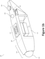
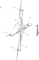
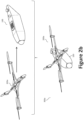
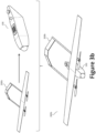
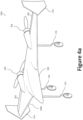
- Three example lift generation modules 200a, 200b, 200c are shown in Figures 2a (a multirotor VTOL lift generation module 200a), 3a (a long-endurance lift generation module 200b), and 4a (a high-speed lift generation module 200c). Additional combinations of functionality are enabled through the modular payload 114 that can be removable coupled to the aerial vehicle (e.g., via the airframe 102 of the fuselage module 100).
- the power unit 116 generates (or provides) the power required to operate the component of the lift generation module(s) 200, avionics and communications systems 120 ( e.g., its flight controller and communications system), payload ( e . g ., modular payload 114), and any other aerial vehicle systems. Power from the power unit 116 can be distributed electrically from the power unit 116, through the attachment interface 110 (using one or more electrical contacts, such as Pogo Pins/pads, and/or a wire connector connection, discussed below), and to the power conditioning electronics in the lift generation module 200 or other payloads.
- the power conditioning electronics may regulate and clean power from the power unit 116 by implementing dynamic power adjustments and removing spikes, surges, noise, sags, and frequency irregularities, which may damage or otherwise adversely affect the performance of the lift generation module 200 or other payloads.
- a power unit 116 may be positioned at the center of the fuselage module 100.
- the power unit 116 may generate its own power, or be charged through a charge port/connector on the fuselage module 100 (e.g., under the control of a processor).
- Charging and discharging of the power unit 116 may be controlled by the fuselage module's 100 flight controller 514 ( e . g ., an aircraft processor 502 and/or control circuitry 504).
- the power unit 116 may be a primary or rechargeable battery (e.g., lithium ion batteries, lead-acid batteries, nickel-metal hydride batteries, nickel-cadmium) or a fuel tank ( e . g ., to hold wet fuel).
- a propulsor refers to a mechanical device that gives propulsion and/or thrust to the aircraft including, without limitation, a motor/engine-driven propellers, jet or turbine engines, vectoring motor pods, etc.
- the power unit 116 may be a battery.
- the power unit 116 may be a fuel tank (optionally with fuel pumps) if the lift generation modules 200 use an engine (e . g ., a wet fuel engine).
- the power unit 116 may be a hybrid-electric system (e . g ., employing an engine-driven generator), in which case the power unit 116 may include a battery, a fuel tank, an engine, and a generator. In operation, the engine burns the fuel stored to the fuel tank to drive the generator, which in turn produces electricity to power the propulsors.
- a hybrid-electric system can offer substantial advantages, but, as can be appreciated, hybrid-electric systems result in additional cost and logistical complexity. For example, hybrid-electric systems provide roughly two to three times the flight time as compared to an aerial vehicle with all-electric battery system of a comparable weight and size (e.g., aerial vehicles under 50 pounds).
- the power unit 116 may be positioned at, or near, the center of gravity of the fuselage module 100 to maintain balance in the aerial vehicle during flight/use across platforms.
- the center of gravity of the fuselage module 100 may be determined using known techniques (e.g., using computer-aided design (CAD) software or using known mathematical equations).
- CAD computer-aided design
- the term center of gravity generally refers to a point at which, if the fuselage module 100 were suspended, it would be balanced in all positions - i.e., fuselage module's 100 hypothetical balancing point in all directions.
- Attachment Interface 110 Figure 1d illustrates a top plan view of an example attachment interface 110.
- the attachment interface 110 which may be sized and shaped as an attachment plate with electrical and mechanical connection/interfaces, provides a connection point between an attachment point of the fuselage module 100 and an attachment point of the lift generation module 200.
- each lift generation module 200 also includes an attachment interface (e.g., a corresponding attachment interface, plate, or other mechanism) sized and shaped to couple to the attachment interface 110 of the fuselage module 100.
- the attachment interface 110 can function as a structural element to join the fuselage module 100 to the lift generation module(s) 200.
- the attachment interface 110 may serve as a male connector, while the corresponding attachment interface on the lift generation module 200 may serve as a female connector (or vice versa).
- the attachment interface 110 can also be used as an electrical connection point, as an electrical connector, or electrical connection may be made as a standalone connector.
- the attachment interface 110 may comprise one or more electrical contacts, such as contact pads and/or electrical contact pins (e.g., spring loaded contact pins, also known as Pogo Pins - described below).
- the attachment interface 110 enables transmission of data (e.g., transmit flight control commands) and/or power between the fuselage module 100 (e.g., the flight controller, power unit, and/or other onboard systems) and the lift generation module 200 (e . g ., propulsors, actuators, and/or other onboard systems) via the corresponding attachment interface positioned on the lift generation module 200.
- the attachment interface 110 may further include one or more retention devices 122 to couple structurally the lift generation module 200 to the fuselage module 100 via the attachment interface 110.
- retention devices 122 may be positioned elsewhere on the fuselage module 100, such as the airframe 102.
- Flight control commands and/or power may be transmitted between the fuselage module 100 and the lift generation module 200 using one or more physical electrical contacts/connectors 124 (e.g., electrical contacts, electrical wires and plugs, etc.).
- the electrical contacts/connectors 124 may be used to transmit flight control commands and/or power from the fuselage module 100 (e.g., the flight controller) to a lift generation module 200, as well as exchanging any required data between the lift generation module 200 and the flight control system of the fuselage module 100.
- a plurality of electrical contact pins may reside on the attachment interface 110 and be configured to electrically couple with one or more electric contact pads on the lift generation module 200 ( e.g., via a corresponding attachment interface at an attachment point).
- the electrical contact pins may be spring loaded to allow for movement while maintaining an electrical connection between the fuselage module 100 and the lift generation module 200.
- the spring-loaded pins may instead be located on the lift generation module 200 side, or a combination thereof.
- the stroking movement of the spring pin piston accommodates uneven non-parallel conditions due to mechanical tolerances in the assembly and during flight. Suitable spring loaded pins include Mill-Max Spring-Loaded (“Pogo Pin”) Contacts.
- Mill-Max Spring Loaded Contacts are button type contacts interconnecting two parallel conductive surfaces inside an electronic device or instrument ( e . g ., between the fuselage module 100 and the lift generation module 200).
- the Pogo Pins and contact pads may be constructed from non-corrosive and/or corrosion-resistant alloys, such as gold-plated brass alloy components and a gold-plated spring.
- data transmission may be accomplished between the fuselage module 100 and the lift generation module 200 using 8 to 12 direct servo channels, as well as network cable (e.g., Ethernet, ribbon cable, optical fiber cable, twisted pair cables, etc.), a serial peripheral interface bus (SPI) (a synchronous serial communication interface specification used for short distance communication), and/or an inter-integrated circuit (I 2 C).
- network cable e.g., Ethernet, ribbon cable, optical fiber cable, twisted pair cables, etc.
- SPI serial peripheral interface bus
- I 2 C inter-integrated circuit
- a wireless transceiver may be employed to communicate data between the fuselage module 100 and the lift generation module 200.
- the wireless transceiver may be a wireless transceiver configured to communicate via one or more wireless standards such as radio-frequency identification (RFID), Near Field Communication (NFC), Bluetooth (e.g., short-wavelength, UHF radio waves in the ISM band from 2.4 to 2.485 GHz), Wi-Fi (e.g., IEEE 802.11 standards), etc.
- RFID radio-frequency identification
- NFC Near Field Communication
- Bluetooth e.g., short-wavelength, UHF radio waves in the ISM band from 2.4 to 2.485 GHz
- Wi-Fi e.g., IEEE 802.11 standards
- the fuselage module 100 may be configured to perform an authentication step to authenticate/validate the lift generation module 200 to ensure compatibility and/or interoperability with the fuselage module 100.
- the fuselage module 100 may request information from the lift generation module 200 relating to the lift generation module's 200 type, operation requirements, manufacturer, age, service history, etc.
- the fuselage module 100 may authenticate the lift generation module 200 using RFID or another communication standard, such as NFC.
- an RFID tag e.g., a passive RFID tag, although active RFID tags are contemplated as well
- the fuselage module's 100 flight controller may adjust (or prohibit) its operation. For example, if the fuselage module's 100 flight controller determines ( e . g ., via aircraft processor 502) that the lift generation module 200 is a multirotor VTOL lift generation module 200a ( e.g., based on data received from the lift generation module 200), the flight controller may employ a predetermined flight operation plan specific to, or designed for, multirotor operation, which may differ from flight operation plans employed, for example, with fixed-wing lift generation modules, such as long-endurance lift generation modules 200b, high-speed lift generation modules 200c, etc.
- fixed-wing lift generation modules such as long-endurance lift generation modules 200b, high-speed lift generation modules 200c, etc.
- the fuselage module's 100 flight controller may notify the operator using an onboard display (e . g ., LED/LCD display positioned on the fuselage module 100), through an audible sound (e.g., an alarm/beep/series of beeps), or through wireless communication with a remote user terminal ( e . g . computer, smart phone, tablet computer, etc.).
- the maintenance status may indicate that service is needed, that service is complete, last service date, upcoming service date, etc.
- the physical electrical contacts/connectors 124 may be further used to transfer power between the fuselage module 100 and the lift generation module 200. While power would traditionally transfer from the fuselage module's 100 power unit 116 to the lift generation module 200, the reverse may occur if the lift generation module 200 includes one or more power generators.
- Example power generators include solar cells/arrays, which may be arranged/installed on the surfaces ( e.g ., wings, airframe, or other generally flat surface) of the lift generation module 200.
- wireless power transmission may be used to transfer power between the fuselage module 100 and the lift generation module 200.
- a wireless power transmitter may be positioned on the fuselage module 100 to transfer power to a wireless power receiver positioned on the lift generation module 200.
- Example wireless power transmission techniques include inductive power transfer (e . g ., magnetic resonance and magnetic induction), resonant inductive coupling, etc.
- Suitable wireless power transfer protocols include, for example, Qi, A4WP, etc.
- the lift generation modules 200 and the modular payload 114 may be removably coupled and configured for easy installation on and/or removal from the airframe 102 to facilitate stowage or to permit use of other lift generation modules 200 ( e.g., replacement or mission-specific).
- the airframe 102 may be provided with one or more retention devices (e.g., mechanical retention devices) to retain passively the modular payload 114 and/or the lift generation module 200 to the aircraft (e.g., airframe 102).
- the retention devices are preferable light in weight and high in strength.
- the retention devices can take the form of snap locks, clips, screws/bolts, magnetic connectors, brackets, screw-threaded mounts, a bayonet-type mounts, breech-lock (friction lock) mounts, hook-and-loop fasteners ( e . g ., Velcro ® ) or a combination thereof.
- Suitable magnets include high-strength neodymium magnets. Neodymium magnets are permanent magnets made from an alloy of neodymium, iron, and boron to form the Nd 2 Fe 14 B tetragonal crystalline structure.
- Another suitable magnet type includes electromagnets, which may be selectively activated or deactivated by the fuselage module 100 ( e . g ., by turning on or off the current supply to the magnet from the power unit 116), which may be controlled by an onboard processor, such as the aircraft processor 502.
- the attachment interface 110 can provide the mechanical connection between the fuselage module 100 and the lift generation module 200 using one or more retention devices 122.
- the retention devices 122 also serve to ensure electrical contact by pressing the Pogo Pins of the attachment interface 110 against their corresponding contact plates on the lift generation module's 200 attachment interface.
- the fuselage module 100 may slideably engage with the lift generation module 200 via the one or more retention devices 122.
- a slideable retention device 122 allows for adjustment of the attachment interface, thereby enabling the operator to select the location at which the lift generation module 200 is positioned on the fuselage module 100, which enables on the fly design adjustments, including adjustment of pitching moment, COG adjustment, etc.
- the fuselage module 100 may be slideably coupled with the lift generation module 200 using, for example, a combination of rails and ball bearings.
- one or both attachment interfaces may include a plurality of distributed retention devices 122.
- the attachment interface 110 may include retention devices 122 distributed along the length of the fuselage module 100 to provide the operator with options when selecting a location (e.g., attachment point) for the attachment interface.
- the retention devices are sufficiently strong to secure the lift generation modules 200 and the modular payload 114 in place during operation, but capable of giving way (e.g., detaching) upon sudden impact (e.g., ground impact, in-air impact, or any other unexpected impact or collision) or intentional disassembly by the operator. Accordingly, during impact, the lift generation modules 200 and the modular payload 114 may eject away from the airframe 102. Without ejecting, a significant portion of the entire vehicle's landing loads would have to travel through the modular payload 114 (and possibly the lift generation module 200), resulting in undesirable damage to the modular payload 114. As such, ejection protects the mechanical components of the lift generation modules 200 and/or the modular payload 114 from damage.
- a plurality of magnets may be mounted on a surface of the airframe 102 (or embedded within the airframe 102) and arranged to mate with corresponding magnets (or metal) positioned at the attachment point (e.g., on an underside surface) of the lift generation module 200, the modular payload 114, or another component. If electromagnets are used, removal of the modular payload 114 and the lift generation module 200 may be achieved by simply disabling the electromagnet(s), whether locally using an electric button/switch or over the network.
- retention devices 122 may provide a mechanical release button on the fuselage module 100 (or the lift generation module 200) to disengage the retention devices 122 or require that the operator apply (e.g., simultaneously) a reasonable push/pull force and twisting (torsional) force to detach a given module from the airframe 102.
- the avionics and communications systems 120 may contain the flight control laws for each compatible lift generation module 200 (e . g ., stored to a memory device), and has the capability to recognize which type (e . g ., fixed-wing, VTOL, propulsor configuration, number/size of propulsors, etc.) of lift generation module 200 is attached via, for example, the above mentioned authentication step.
- the avionics and communications systems 120 also include one or more communication links (e.g., Line-Of-Sight (LOS) and Beyond Line-Of-Sight (BLOS)) to the ground control station, as well as the capability to transmit high-definition video.
- LOS Line-Of-Sight
- BLOS Line-Of-Sight
- the avionics and communications systems 120 may contain several sensors including a barometric altimeter, inertial measurement unit (IMU), GPS, and a micro-radar for use as a radar altimeter. Additional sensors can be integrated with different lift generation modules 200 systems as appropriate - for example, collision avoidance sensors may be provided on the hovering lift generation modules multirotor VTOL lift generation module 200a or a pitot probe on a fixed-wing lift generation module, such as the long-endurance lift generation module 200b and the high-speed lift generation module 200c.
- the avionics and communications system 120 may be modular to allow forward compatibility with new sensors and hardware that is rapidly being developed.
- the structural components of the fuselage module 100 and/or the lift generation module(s) 200 may be fabricated from one or more of metal, foam, carbon fiber, or another composite material.
- small, lightweight modular UAS may employ foam, with larger aircraft employing a composite material, metal, or a combination thereof (e.g., a metal alloy frame, stringers, and longerons and/or a composite material skin).
- the structure is concentrated on the top and bottom in semi-monocoque structure. The top carries the main flight bending and attachment loads, while the bottom is reinforced to enable belly landings. Stringers and longerons may be used to carry the loads between the top and bottom sections.
- the fuselage module 100 may also incorporate skids or landing gear.
- the fuselage module 100 may include landing gear when configured as a hovering configuration 300a (such as skids) or a long-endurance configuration 300b, but, when configured as a high-speed configuration 300c, the landing gear may be coupled to the high-speed lift generation module 200c.
- Modular payload 114 The system features the ability to interface with several different modular payloads 114.
- the modular payload 114 may employ one or more of the structural and/or communication/power connection interfaces discussed above with regard to the attachment interface 110 and the lift generation modules 200.
- the modular payload 114 illustrated in Figures 1a-1c can be replaced by simply interchanging the nose of the aerial vehicle.
- the nose may be permanent with an interchangeable payload bay or assembly positioned within the nose (e.g., accessible via an access panel).
- Communications from the flight controller to the modular payload 114 may be the same as the communication techniques used between the flight controller and the lift generation modules 200 (e.g., servo channels, Ethernet, I 2 C/SPI, and power). Any required voltage conversion can be performed using power conditioning electronics included with the payload.
- the flight controller will be able to detect the type of payload in use and receive feedback from it if appropriate, thereby allowing for the possibility of tight payload integration, and possibly use of payload sensors for a flight controller.
- the payload sensors may include, without limitation, ultrasonic sensors, infrared sensors, radar, LIDAR (light imaging, detection, and ranging), thermal cameras (e.g., FLIR), and the like.
- the modular payload 114 may be equipped with a traditional intelligence, surveillance, and reconnaissance (ISR) payload.
- ISR intelligence, surveillance, and reconnaissance
- the modular payload 114 may be equipped with one or more cameras, audio devices, and other sensors. Any video, image, audio, telemetry, and/or other sensor data collected may be stored locally or communicated wirelessly from the aircraft to a remote location (e.g., a ground control station) in real time using an antenna coupled with an onboard wireless communication device ( e .
- the avionics and communications system 120 such as a transmitter/receiver.
- information may be communicated, or otherwise transferred, to the remote location or another party via a wired connection ( e . g ., if the aircraft is tethered or landed).
- Lift Generation Modules 200 illustrates the fuselage module 100 with a plurality of different lift generation modules 200, including a multirotor VTOL lift generation module 200a to provide VTOL operation, a long-endurance lift generation module 200b to provide increased flight time, and a high-speed lift generation module 200c to provide high-speed operation.
- the various lift generation modules 200 provide, for example, lifting surfaces, propulsors, onboard circuitry 218 (e.g., power conditioning electronics), speed controllers (e . g ., electronic speed controllers (ESC) 226), flight control actuators, and surfaces/flight control surfaces.
- the lift generation modules 200 may also include additional systems, such as fixed or retractable landing gear and/or specialized configuration-specific sensors.
- Flight control inputs to the lift generation modules 200 originate with the main flight control system of the fuselage module 100. While the lift generation modules 200 vary in terms of features and hardware, each includes an attachment interface sized, shaped, and otherwise configured to mate with the attachment interface 110 of the fuselage module 100. As one of skill in the art would appreciate, the fuselage module 100 and the plurality of lift generation modules 200 can be scaled up or down to facilitate a particular purpose or mission.
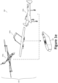
- FIG. 300a illustrates an example multirotor VTOL lift generation module 200a
- Figure 2b illustrates the fuselage module 100 configured with the multirotor VTOL lift generation module 200a in a hovering configuration 300a
- a multirotor VTOL lift generation module 200a generally comprises a support frame 204, a plurality of longitudinal booms 206 extending radially from the support frame 204, a plurality of propulsors 202, and a plurality of ESC 226 to control the speed of the propulsors 202.
- each propulsor 202 may be coupled to the ESC 226 via a drive-power link 226a (e.g., a cable).
- a drive-power link 226a e.g., a cable
- the ESC 226, is coupled (through the attachment interface) to the power unit 116 via one or more input power links 226b and to the flight controller via one or more data links 226c.
- the ESC 226 may be coupled directly to the power unit 116 via the input power link 226c or through the flight controller.
- Each of said plurality of propulsors 202 may be placed at a distal end of a longitudinal boom 206 and oriented to direct thrust downward (relative to the vehicle).
- multirotor VTOL lift generation module 200a is illustrated as having four propulsors 202, a person of skill in the art would recognize that additional, or fewer, propulsors 202 may be employed depending on the aircraft size and weight (e.g., about 1 to 12 propulsors, more preferable about 2 to 8 propulsors, most preferably about 4 to 6 propulsors).
- the multirotor VTOL lift generation module 200a may also include collision avoidance sensors of various types to enable the aircraft to perform multirotor missions (e.g., close-up inspection, maneuvering through confined areas, aerial photography) with the same flight time and payload limitations provided by traditional multirotor configuration systems.
- Figure 3a illustrates an example long-endurance lift generation module 200b
- Figure 3b illustrates the fuselage module 100 configured with the long-endurance lift generation module 200b in a long-endurance configuration 300b.
- a long-endurance lift generation module 200a generally comprises two wings 208a (together defining a wing set), a plurality of longitudinal booms 206 extending aft from the wing set, a plurality of propulsors 202 (e.g., as illustrated, a rotor having a motor/engine-driven propeller), a plurality of ESCs 226 (not illustrated) to control the speed of the propulsors 202, and an empennage 210.
- the ESCs 226 may be, for example, embedded in the airframe ( e . g ., fuselage portion 228 or wings 208) of the lift generation module 200.
- the wings 208a may employ one or more control surfaces 302, such as a single conventional aileron configuration or, in the alternative, a plurality of spanwise distributed, independently actuated, ailerons ( e . g ., wing-borne control surfaces), or flaperons, which is a type of aircraft control surface that combines aspects of both flaps and ailerons.
- ailerons e . g ., wing-borne control surfaces
- flaperons which is a type of aircraft control surface that combines aspects of both flaps and ailerons.
- the one or more control surfaces 302 may be positioned at the trailing edge of the wings 208a and/or empennage 210.
- the flaperon may incorporate one or more types of flaps or flap features, including, without limitation, plain, split, slotted, Fowler, Junkers Flap Gouge, Fairey-Youngman, Zap, Krueger, Gurney, and, in certain aspects, leading edge flaps, such as leading edge droop and blown flaps.
- a winglet 214 may be provided at the distal end of each wing 208a to, inter alia, improve aircraft handling characteristics, enhance safety, and improve efficiency of the aerial vehicle.
- the wings 208a may further utilize a continuous set of sensors (e . g ., strain/torque measurement sensors) along each wing 208a to manipulate the spanwise, continuous, trailing edge surface (e.g., the flaperons), much in the way a bird is known to alter its wing shape.
- an aircraft in the long-endurance configuration 300b is hand launched and belly lands, although landing gear 216 may be included.
- a pitot probe may be included on the wings 208a to feed data back to the flight control system.
- the wings 208a, longitudinal booms 212, and empennage 210 can be disassembled for easy transport. While the long-endurance lift generation module 200b is illustrated as having two propulsors 202, a person of skill in the art would recognize that additional, or fewer, propulsors 202 may be employed depending on the aircraft size and weight.
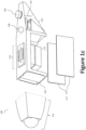
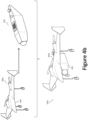
- FIG. 3a illustrates an example high-speed lift generation module 200c
- Figure 4b illustrates the fuselage module 100 configured with the high-speed lift generation module 200c in a high-speed configuration 300c.
- the high-speed configuration may be desirable when maximum speed is needed instead of flight time - for example, conducting rapid assessment operations or delivering critical supplies.
- a high-speed lift generation module 200c may employ a flying wing design generally comprising a fuselage portion 228, two wings 208b (together defining a wing set), and winglets 214. Akin to the long-endurance lift generation module 200a, the wings 208b may employ one or more control surfaces. While not illustrated, an empennage may be situated at the aft end of the high-speed lift generation module 200c.
- the high-speed lift generation module 200c also includes a plurality of propulsors 202 coupled to, for example, the wings 208b and/or fuselage portion 228. The propulsors 202 may be arranged in a tractor configuration or, as illustrated, a pusher configuration.
- the high-speed lift generation module 200c may employ landing gear 216, which may be fixed or retractable. While the high-speed lift generation module 200c is illustrated as having two propulsors 202, a person of skill in the art would recognize that additional, or fewer, propulsors 202 may be employed depending on the aircraft size and weight.
- the empennage when an empennage is employed on the aircraft, the empennage may be modular and removably coupled to the fuselage module 100 and/or lift generation module 200.
- empennage tail configurations include, for example, V-Tail, inverted V-Tail, H-Tail, etc.
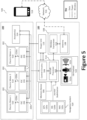
- FIG. 5 illustrates a block diagram of an example aircraft control system 500 for the above-described aircraft and aerial systems (e . g ., fuselage module 100 configured with a lift generation module 200 in a hovering configuration 300a, a long-endurance configuration 300b, a high-speed configuration 300c, etc.).
- the aircraft control system 500 can be configured to control the various aircraft components and functions of the aircraft.
- the aircraft control system 500 includes one or more flight controllers 514 (e . g ., an aircraft processor 502 and associated control circuitry 504) communicatively coupled with at least one memory device 506, a communications system 508 ( e . g ., a wireless transceiver 512 and antenna 108), and a navigation system 520.
- flight controllers 514 e . g ., an aircraft processor 502 and associated control circuitry 504
- the aircraft control system 500 includes one or more flight controllers 514 (e . g ., an aircraft processor 502 and associated control circuitry 504)
- the aircraft processor 502 may be configured to perform one or more operations based at least in part on instructions (e . g ., software, firmware, etc.) and/or one or more databases stored to the memory device 506 (e . g ., hard drive, flash memory, or the like).
- the at least one memory device 506 may be integral with the flight controller 514.
- the one or more flight controllers 514 may also be operatively coupled with the power unit 116 and an ISR payload 522.
- the power unit 116 may provide the power to needed operate the various components of the aircraft control system 500, through some power connection lines may not be illustrated in Figure 5 .
- the power unit 116 may provide both power and data ( e .
- the aircraft controller 514 may use the status data to determine the power unit's 116 remaining capacity and/or, in the case of battery-powered systems, the state-of-charge or state-of-heath of the battery.
- the status data e.g., battery voltage, amperage, fuel level, temperature, etc.
- the aircraft controller 514 may use the aircraft controller 514 to determine the power unit's 116 remaining capacity and/or, in the case of battery-powered systems, the state-of-charge or state-of-heath of the battery.
- the aerial system or aircraft control system 500 may further include other desired services, such as a communications system 508 (e . g ., wireless transceiver 512 coupled with an antenna 108) to communicate data between the aircraft (e . g ., the flight controller 514) and a remote device 518 ( e . g ., portable electronic devices, such as smartphones, tablets, and laptop computers) or other remotely-situated controller ( e . g ., a base station).
- the aircraft may communicate data (processed data, unprocessed data, etc.) with the remote device 518 over a network 516.
- the wireless transceiver 512 may be configured to communicate using one or more wireless standards such as Bluetooth ( e .
- the remote device 518 may facilitate monitoring and/or control of the aircraft and its payload(s), including the ISR payload 522.
- the aircraft processor 502 may be operatively coupled to the control circuitry 504 to control operation of the various actuators 524 (e.g., those to control movement of flight surfaces), propulsors 202 (e.g., a propeller driven by an electric motor 510 coupled to an ESC 226) in response to commands from an operator, autopilot, a navigation system 520, or other high-level system via the wireless transceiver 512.
- the aircraft processor 502 and the control circuitry 504 may be integrated to provide the flight controller 514 as a single component (e . g ., a single printed circuit board (PCB)) or circuit.
- the flight controller 514 may dynamically ( i .
- the flight controller 514 can independently control each of the electric motors 510 to generate a desired lift thrust for each of the electric motors 510, whether directly of via an ESC 226.
- the flight controller 514 can be operatively coupled with the power unit 116 directly or via an ESC 226.
- the flight controller 514 may vary the revolutions per minute (RPM) of the rotor and/or, where desired, vary the pitch of the rotor blades.
- the electric motors 510 may be controlled by adjusting power supplied to each electric motor from a power unit 116 (e.g., a battery pack, a battery bank, hybrid-electric power system, etc.) via the ESC 226.
- the aircraft processor 502 may be operatively coupled to the navigation system 520, which may include a global positioning system (GPS) 520a that is communicatively coupled with an Inertial Navigation System (INS) 520b and/or an inertial measurement unit (IMU) 520c, which can include one or more gyros and accelerometers.
- GPS global positioning system
- INS Inertial Navigation System
- IMU inertial measurement unit
- the GPS 520a gives an absolute drift-free position value that can be used to reset the INS solution or can be blended with it by use of a mathematical algorithm, such as a Kalman Filter.
- the navigation system 520 may communicate, inter alia, inertial stabilization data to the aircraft processor 502.
- the aircraft or aircraft control system 500 may further be equipped with an intelligence, surveillance, and reconnaissance (ISR) payload 522 comprising, for example, one or more cameras 522a (e.g., payload camera 104, or another an optical instrument for recording or capturing images and/or video, including light detection and ranging (LIDAR) devices), audio devices 522b (e.g., microphones, echolocation sensors, etc.), and other sensors 522c to facilitated ISR functionality and provide ISR data (e.g. photographs, video, audio, sensor measurements, etc.).
- the ISR payload 522 is operatively coupled to the aircraft processor 502 to facilitate communication of the ISR data between the ISR payload 522 and the aircraft processor 502.
- the ISR data may be used to navigate the aircraft.
- the ISR payload 522 may be rotatably and pivotally coupled to, for example, the underside surface of the airframe 102 (or another structural component, such as the longitudinal booms 206, 212) via a gimbal system to enable the ISR payload 522 to be more easily oriented downward to monitor objects below and/or on the ground.
- a sensor payload may be positioned at the forward end of the fuselage module 100 as part of the modular payload 114.
- the data may be dynamically or periodically communicated from the aircraft (e.g., the aircraft control system 500 to the remote device 518 over the network 516 via the wireless transceiver 512, or stored to the memory device 506 for later access or processing.
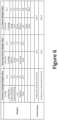
- Performance Evaluation With reference to Figures 6 and 7 , a performance assessment was conducted for several example configurations to assess the advantages of the modular UAS. The assessment was focused around an initial vehicle in the 20-pound weight class. A larger vehicle with a hybrid-electric power system, in the 30 to 40 pound range, was also investigated. In all cases, 5 pounds of on-board payload was assumed. A common fuselage module 100 was sized based on an existing power generation system (hybrid electric or batteries) and known weight fractions/sub-system weights. Lift generation module 200 system weights were computed based on weight fractions of existing aerial vehicles and known subsystem weights. The performance of the systems was then assessed using existing analysis methods.
- existing power generation system hybrid electric or batteries
- Lift generation module 200 system weights were computed based on weight fractions of existing aerial vehicles and known subsystem weights.
- the vehicle performance shown in Figure 6 is based on propulsion system weights and performance developed for a hybrid-electric multi-copter program.
- Energy generation can refer to either battery or a hybrid-electric system.
- the endurance numbers for both variants are shown.
- Hybrid-electric systems offer the potential for vastly increased system performance, at the expense of higher cost and increased logistical and system complexity. That makes this architecture especially attractive for hybrid-electric systems, as those systems will have high re-use across a variety of missions.
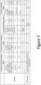
- Figure 7 shows the performance estimates for a smaller variant, sized around the fixed-wing 20 propulsion system and payload.
- This is an electric-only system, and comprises a third, high-speed variant as well as a long-endurance and hovering configurations.
- This shows similar performance to the all-electric systems in Figure 6 .
- the main benefit of going to the larger aerial vehicles is that they would enable the use of hybrid-electric systems.
- the presently disclosed concept can be sized up and down for virtually any desired payload or mission capability.
- the subject modular UAS may be applied across a variety of markets that use sUAS systems, as most consumers of sUAS systems desire different capability at different times. For example, first responders in disaster relief efforts may need to map quickly an effected area, set up a persistent surveillance capability, and do closer inspections of areas of interest in addition to delivering high-value medical supplies. However, doing all of that with one vehicle enforces an excessive number of tradeoffs on the vehicle design, or it means doing everything with multi-rotors, which can be logistically limiting. Long-endurance variants can be deployed to provide persistent surveillance from open areas, while the high-speed aerial vehicles could be launched from a road to provide mapping and rapid delivery capability.
- Multi-rotor variants would be used for those tasks which best fit their capability - precision delivery, inspection, and maneuvering through combined areas.
- Police, fire fighters, surveyors, and newscasters face a need for a similar diversity of capabilities.
- Many events take place over more than 20 or 30 minutes (the flight time of a typical multi-rotor system), where it is not always feasible or desirable to use a fixed-wing vehicle.
- many consumers of sUAS systems need different capabilities at different times, but operating many different families of aerial vehicles is expensive and hampered by non-common command and control and data systems.
- the modular UAS concept disclosed herein provides a diverse range of capabilities in an integrated system.
Landscapes
- Engineering & Computer Science (AREA)
- Aviation & Aerospace Engineering (AREA)
- Mechanical Engineering (AREA)
- Remote Sensing (AREA)
- Charge And Discharge Circuits For Batteries Or The Like (AREA)
- Details Of Aerials (AREA)
- Electric Propulsion And Braking For Vehicles (AREA)
- Toys (AREA)
Claims (14)
- Luftfahrzeugrumpf, der ein Rumpfmodul (100) umfasst, wobei das Rumpfmodul (100) Folgendes umfasst:eine Flugsteuerung (514), die mit einer Leistungseinheit (116) wirkgekoppelt ist; undein Kommunikationssystem (120, 508), das mit der Flugsteuerung (514) wirkgekoppelt ist,wobei der Luftfahrzeugrumpf dazu ausgelegt ist, an einem Befestigungspunkt des Luftfahrzeugrumpfs über eine Befestigungsschnittstelle (110) entfernbar mit einem einer Mehrzahl von Auftriebserzeugungsmodulen (200, 200a, 200b, 200c) gekoppelt zu werden,wobei sich eine Mehrzahl von elektrischen Kontakten an dem Befestigungspunkt befindet, um eine elektrische Kommunikation zwischen der Flugsteuerung (514) und dem einen einer Mehrzahl von Auftriebserzeugungsmodulen (200, 200a, 200b, 200c) zu ermöglichen,wobei die Leistungseinheit (116), die Flugsteuerung (514) und das Kommunikationssystem (120, 508) in einem Flugwerk (102) positioniert sind, um das Rumpfmodul (100) zu definieren, wobei die Befestigungsschnittstelle (110) mit dem Flugwerk (102) gekoppelt und dazu ausgelegt ist, über eine oder mehrere Haltevorrichtungen (122) strukturell mit einer zweiten Befestigungsschnittstelle des einen einer Mehrzahl von Auftriebserzeugungsmodulen (200, 200a, 200b, 200c) gekoppelt zu werden,dadurch gekennzeichnet, dass entweder:das Rumpfmodul (100) dazu ausgelegt ist, gleitend mit dem einen einer Mehrzahl von Auftriebserzeugungsmodulen (200, 200a, 200b, 200c) derart in Eingriff zu kommen, dass die Lage, in der das eine einer Mehrzahl von Auftriebserzeugungsmodulen (200, 200a, 200b, 200c) auf dem Rumpfmodul (100) positioniert ist, auswählbar ist; oderdie Befestigungsschnittstelle (110) eine Mehrzahl von verteilten Haltevorrichtungen (122) umfasst, wobei die Mehrzahl von verteilten Haltevorrichtungen (122) entlang der Länge des Rumpfmoduls (100) verteilt sind, um einem Bediener eine Mehrzahl von Optionen bei Auswählen des Befestigungspunkts des Luftfahrzeugrumpfs bereitzustellen.
- Luftfahrzeugrumpf nach Anspruch 1, wobei das Rumpfmodul (100) dazu ausgelegt ist, das eine der Mehrzahl von Auftriebserzeugungsmodulen (200, 200a, 200b, 200c) zu authentifizieren, um eine Kompatibilität und/oder Interoperabilität mit dem Luftfahrzeugrumpfmodul (100) sicherzustellen.
- Luftfahrzeugrumpf nach Anspruch 1 oder 2, wobei die eine oder mehreren Haltevorrichtungen (122) einen Magnetverbinder umfassen.
- Luftfahrzeugrumpf nach Anspruch 1, wobei die Flugsteuerung (514) dazu ausgelegt ist, die Leistungseinheit (116) über einen oder mehrere der Mehrzahl von elektrischen Kontakten mit dem einen der Mehrzahl von Auftriebserzeugungsmodulen (200, 200a, 200b, 200c) elektrisch zu koppeln.
- Luftfahrzeugrumpf nach Anspruch 1, wobei mindestens eines der Flugsteuerung (514) und/oder des Kommunikationssystems (120, 508) dazu ausgelegt ist, Daten über einen oder mehrere der Mehrzahl von elektrischen Kontakten mit dem einen der Mehrzahl von Auftriebserzeugungsmodulen (200, 200a, 200b, 200c) zu kommunizieren.
- Luftfahrzeugrumpf nach Anspruch 1, wobei die Leistungseinheit (116) ein hybrid-elektrisches System ist, das dazu ausgelegt ist, Strom über einen motorbetriebenen Generator zu erzeugen.
- Luftfahrzeugrumpf nach einem der vorhergehenden Ansprüche, wobei das Rumpfmodul (100) dazu ausgelegt ist, Informationen in Bezug auf den Typ, Betriebsanforderungen den Hersteller, das Alter oder die Wartungshistorie des einen der Mehrzahl von Auftriebserzeugungsmodulen (200, 200a, 200b, 200c) von dem einen der Mehrzahl von Auftriebserzeugungsmodulen (200, 200a, 200b, 200c) anzufordern.
- Luftfahrzeugrumpf nach Anspruch 7, wobei das Rumpfmodul (100) dazu ausgelegt ist, das eine der Mehrzahl von Auftriebserzeugungsmodulen (200, 200a, 200b, 200c) unter Verwendung einer Hochfrequenz-Identifikation, RFID, zu authentifizieren.
- Luftfahrzeugrumpf nach Anspruch 8, wobei das Rumpfmodul (100) ferner einen RFID-Leser umfasst, wobei das eine der Mehrzahl von Auftriebserzeugungsmodulen (200, 200a, 200b, 200c) ferner einen RFID-Transponder umfasst.
- Verfahren zum Verbessern einer Betriebsfähigkeit eines Luftfahrzeugsystems, wobei das Verfahren Folgendes umfasst:Bereitstellen eines Rumpfmoduls (100), das eine erste Befestigungsschnittstelle (110), eine Flugsteuerung (514), die mit einer Leistungseinheit (116) wirkgekoppelt ist, und ein Kommunikationssystem (120, 508), das mit der Flugsteuerung (514) wirkgekoppelt ist, umfasst; undBereitstellen eines Auftriebserzeugungsmoduls (200, 200a, 200b, 200c), das eine zweite Befestigungsschnittstelle und eine Mehrzahl von Propulsoren umfasst,wobei das Rumpfmodul (100) dazu ausgelegt ist, über die erste und die zweite Befestigungsschnittstelle (110) entfernbar mit dem Auftriebserzeugungsmodul (200, 200a, 200b, 200c) gekoppelt zu werden,wobei die erste und die zweite Befestigungsschnittstelle (1) eine Mehrzahl von elektrischen Kontakten zum Ermöglichen einer elektrischen Kommunikation zwischen dem Rumpfmodul (100) und dem Auftriebserzeugungsmodul (200, 200a, 200b, 200c) und (2) eine oder mehrere Haltevorrichtungen (122) zum strukturellen Koppeln des Auftriebserzeugungsmoduls (200, 200a, 200b, 200c) mit der Befestigungsschnittstelle (110) umfasst, undwobei entweder:das Rumpfmodul (100) dazu ausgelegt ist, gleitend mit dem Auftriebserzeugungsmodul (200, 200a, 200b, 200c) derart in Eingriff zu kommen, dass die Lage, in der das Auftriebserzeugungsmodul (200, 200a, 200b, 200c) auf dem Rumpfmodul positioniert ist, auswählbar (100) ist; odereine oder beide der ersten Befestigungsschnittstelle und der zweiten Befestigungsschnittstelle (110) eine Mehrzahl von verteilten Haltevorrichtungen (122) umfasst, wobei die Mehrzahl von verteilten Haltevorrichtungen (122) entlang der Länge des Rumpfmoduls (100) verteilt sind, um einem Bediener eine Mehrzahl von Optionen bei Auswählen des Befestigungspunkts des Luftfahrzeugrumpfs bereitzustellen.
- Verfahren nach Anspruch 10, ferner umfassend den Schritt entfernbares Koppeln des Auftriebserzeugungsmoduls (200, 200a, 200b, 200c) mit dem Rumpfmodul (100).
- Verfahren nach Anspruch 10, wobei das Rumpfmodul (100) dazu ausgelegt ist, das eine der Mehrzahl von Auftriebserzeugungsmodulen (200, 200a, 200b, 200c) unter Verwendung einer Hochfrequenz-Identifikation, RFID, zu authentifizieren.
- Verfahren nach Anspruch 12, wobei das Rumpfmodul (100) einen RFID-Leser umfasst und das Auftriebserzeugungsmodul (200, 200a, 200b, 200c) einen RFID-Transponder umfasst.
- Verfahren nach Anspruch 13, wobei das Rumpfmodul (100) Informationen von dem RFID-Transponder bei Bestimmen, ob oder ob nicht das Auftriebserzeugungsmodul (200, 200a, 200b, 200c) authentifiziert werden soll, verarbeitet.
Applications Claiming Priority (2)
| Application Number | Priority Date | Filing Date | Title |
|---|---|---|---|
| US201762474721P | 2017-03-22 | 2017-03-22 | |
| PCT/US2018/023717 WO2018175694A1 (en) | 2017-03-22 | 2018-03-22 | Multi-architecture modular unmanned aerial system |
Publications (3)
| Publication Number | Publication Date |
|---|---|
| EP3601042A1 EP3601042A1 (de) | 2020-02-05 |
| EP3601042A4 EP3601042A4 (de) | 2021-01-13 |
| EP3601042B1 true EP3601042B1 (de) | 2024-03-13 |
Family
ID=63581607
Family Applications (1)
| Application Number | Title | Priority Date | Filing Date |
|---|---|---|---|
| EP18771479.5A Active EP3601042B1 (de) | 2017-03-22 | 2018-03-22 | Architektur für ein modulares unbemanntes luftfahrzeugsystem |
Country Status (4)
| Country | Link |
|---|---|
| US (1) | US10870479B2 (de) |
| EP (1) | EP3601042B1 (de) |
| CN (1) | CN109715497A (de) |
| WO (1) | WO2018175694A1 (de) |
Families Citing this family (48)
| Publication number | Priority date | Publication date | Assignee | Title |
|---|---|---|---|---|
| WO2016155400A1 (zh) * | 2015-03-31 | 2016-10-06 | 珠海羽人农业航空有限公司 | 多功能飞行平台 |
| WO2019048996A1 (en) * | 2017-09-09 | 2019-03-14 | Ideaforge Technology Pvt. Ltd. | UNPLANE FRAME STRUCTURE OF AN AIR VEHICLE WITHOUT PILOT |
| US11565810B2 (en) * | 2017-10-10 | 2023-01-31 | Aeronext Inc. | Flying body |
| BR112020009376A2 (pt) * | 2017-11-13 | 2020-10-13 | Total Sa | dirigível híbrido e método de montagem e/ ou manutenção de um dirigível híbrido |
| US10723433B2 (en) * | 2017-11-27 | 2020-07-28 | Wing Aviation Llc | Assembly systems and methods for unmanned aerial vehicles |
| US11034445B2 (en) | 2017-11-27 | 2021-06-15 | Wing Aviation Llc | Wing structure and attachment to frame for unmanned aerial vehicles |
| US20190166420A1 (en) * | 2017-11-29 | 2019-05-30 | Packet Digital, Llc | Uas surveillance and communication package |
| ES2933378T3 (es) * | 2018-04-27 | 2023-02-06 | Textron Systems Corp | Conjunto de rotor de paso variable para aplicaciones de aeronave de empuje vectorizado accionada eléctricamente |
| US11124283B1 (en) * | 2018-06-24 | 2021-09-21 | Adam Wade Kennedy | Wing in ground effect vehicle |
| US11521500B1 (en) * | 2018-10-17 | 2022-12-06 | Amazon Technologies, Inc. | Unmanned aerial systems with range finding |
| JP7033052B2 (ja) * | 2018-11-26 | 2022-03-09 | 本田技研工業株式会社 | 電源装置、および飛行体 |
| JP7032290B2 (ja) * | 2018-11-26 | 2022-03-08 | 本田技研工業株式会社 | 電源装置及び飛行体 |
| JP2020083066A (ja) * | 2018-11-26 | 2020-06-04 | 本田技研工業株式会社 | 電源装置、および飛行体 |
| CN111216901A (zh) | 2018-11-26 | 2020-06-02 | 本田技研工业株式会社 | 电源装置以及飞行体 |
| JP7032289B2 (ja) * | 2018-11-26 | 2022-03-08 | 本田技研工業株式会社 | 電源装置、および飛行体 |
| US10787255B2 (en) | 2018-11-30 | 2020-09-29 | Sky Canoe Inc. | Aerial vehicle with enhanced pitch control and interchangeable components |
| US10611479B1 (en) * | 2019-01-18 | 2020-04-07 | Bell Textron Inc. | Inset turret assemblies for aircraft |
| US10822085B2 (en) * | 2019-03-06 | 2020-11-03 | Rantizo, Inc. | Automated cartridge replacement system for unmanned aerial vehicle |
| US20200317324A1 (en) * | 2019-04-02 | 2020-10-08 | Thomas Andrew Youmans | Modular apparatus, design, concept for modules, connection, attachment and capability adding structural add ons for vehicles, structures |
| BR122023022026A2 (pt) * | 2019-04-11 | 2024-01-16 | Pilatus Flugzeugwerke Ag | Compartimento de energia conformal |
| US11724804B2 (en) * | 2019-04-11 | 2023-08-15 | Textron Innovations Inc. | Aircraft coupling mechanism |
| US11796321B2 (en) | 2019-06-18 | 2023-10-24 | The Boeing Company | System for pod-based transportation |
| US11752916B2 (en) * | 2019-06-18 | 2023-09-12 | The Boeing Company | Pod-centric module integration with a vehicle |
| CN110203383B (zh) * | 2019-06-24 | 2024-04-16 | 南京航空航天大学 | 一种模块化的交叉式纵列无人直升机及其工作方法 |
| US11628932B2 (en) * | 2019-08-13 | 2023-04-18 | Doosan Mobility Innovation Inc. | Multicopter |
| US11884391B2 (en) * | 2019-10-14 | 2024-01-30 | Elroy Air, Inc. | Mission pod for unattended UAV operations |
| CN110615097A (zh) * | 2019-10-23 | 2019-12-27 | 深圳市道通智能航空技术有限公司 | 一种无人飞行器 |
| JP7209399B2 (ja) * | 2019-11-15 | 2023-01-20 | 株式会社石川エナジーリサーチ | 飛行装置 |
| US11953916B2 (en) | 2020-01-31 | 2024-04-09 | The Boeing Company | Transportation pod that deploys from an aircraft or vehicle |
| JP7479163B2 (ja) | 2020-02-26 | 2024-05-08 | 本田技研工業株式会社 | 電源装置 |
| JP7478551B2 (ja) | 2020-02-28 | 2024-05-07 | 本田技研工業株式会社 | 推進装置、および飛行体 |
| US11820526B2 (en) * | 2020-02-26 | 2023-11-21 | Honda Motor Co., Ltd. | Power supply apparatus for a flying body including a combustion gas and intake air heat exchanger |
| US11794931B2 (en) * | 2020-04-02 | 2023-10-24 | United Parcel Service Of America, Inc. | Modular unmanned aerial vehicle system for adaptable parcel delivery |
| WO2021198671A1 (en) * | 2020-04-02 | 2021-10-07 | Bae Systems Plc | Aircraft |
| CN212099364U (zh) * | 2020-04-02 | 2020-12-08 | 山东顶峰航空科技有限公司 | 一种能源载荷总成及无人机 |
| CN212125495U (zh) * | 2020-04-03 | 2020-12-11 | 山东顶峰航空科技有限公司 | 一种快拆结构及无人机 |
| US11958601B2 (en) * | 2020-04-14 | 2024-04-16 | Aurora Flight Sciences Corporation | Unmanned aerial aquatic platform with battery management |
| US20220080478A1 (en) * | 2020-09-14 | 2022-03-17 | Shang-Jung Wu | Management station of multi-point time-sharing water quality monitoring system |
| US20220177109A1 (en) * | 2020-12-09 | 2022-06-09 | Bell Textron Inc. | Detect and avoid sensor integration |
| WO2022120796A1 (zh) * | 2020-12-11 | 2022-06-16 | 深圳市大疆创新科技有限公司 | 模块化无人飞行器及其操作方法 |
| WO2022140362A1 (en) * | 2020-12-21 | 2022-06-30 | Texas Tech University System | Reconfigurable unmanned vehicles |
| CN113581477B (zh) * | 2021-06-29 | 2024-04-26 | 成都纵横大鹏无人机科技有限公司 | 一种功能模块安装结构及采用其的飞行器 |
| CN113682475A (zh) * | 2021-08-27 | 2021-11-23 | 沈阳无距科技有限公司 | 一种模块化无人机 |
| US11753137B2 (en) * | 2021-08-31 | 2023-09-12 | Textron Systems Corporation | Utilizing a customizable fuselage assembly for an unmanned aerial vehicle |
| US11745890B1 (en) | 2022-04-29 | 2023-09-05 | Beta Air, Llc | Fuel pod for hybrid electric aircraft |
| WO2023220447A2 (en) * | 2022-05-13 | 2023-11-16 | Firestorm Labs, Inc. | Mission-adaptable aerial vehicle and methods for in-field assembly and use |
| US11981460B2 (en) | 2022-05-13 | 2024-05-14 | Firestorm Labs, Inc. | Mission-adaptable aerial vehicle and methods for in-field assembly and use |
| CN116891014B (zh) * | 2023-09-07 | 2023-11-14 | 太原科技大学 | 基于模块化的多模式无人机 |
Family Cites Families (28)
| Publication number | Priority date | Publication date | Assignee | Title |
|---|---|---|---|---|
| US3640492A (en) | 1970-02-19 | 1972-02-08 | Northrop Corp | Modular aircraft structures |
| US5941478A (en) | 1998-04-28 | 1999-08-24 | Freewing Aerial Robotics Corporation | STOL/VTOL free wing aircraft with modular wing and tail |
| JP2001347996A (ja) * | 2000-06-06 | 2001-12-18 | Mitsubishi Heavy Ind Ltd | 航空機の主翼位置移動装置 |
| US6575406B2 (en) | 2001-01-19 | 2003-06-10 | The Boeing Company | Integrated and/or modular high-speed aircraft |
| GB0116219D0 (en) | 2001-07-03 | 2002-03-06 | Bae Systems Plc | An aircraft |
| US6840480B2 (en) * | 2001-09-27 | 2005-01-11 | Ernest A. Carroll | Miniature, unmanned aircraft with interchangeable data module |
| US6726148B2 (en) | 2001-09-27 | 2004-04-27 | Ernest A. Carroll | Manually disassembled and readily shippable miniature, unmanned aircraft with data handling capability |
| US7234667B1 (en) | 2003-12-11 | 2007-06-26 | Talmage Jr Robert N | Modular aerospace plane |
| US7946530B1 (en) | 2005-06-13 | 2011-05-24 | Talmage Jr Robert N | Modular adaptive configured helicopter |
| US7922115B2 (en) | 2006-04-21 | 2011-04-12 | Colgren Richard D | Modular unmanned air-vehicle |
| US7699261B2 (en) | 2007-03-05 | 2010-04-20 | Lockheed Martin Corporation | Small unmanned airborne vehicle airframe |
| KR20120082394A (ko) | 2009-07-22 | 2012-07-23 | 에어로바이론먼트, 인크. | 재구성가능한 비행기 |
| WO2011146349A2 (en) | 2010-05-17 | 2011-11-24 | Piasecki Aircraft Corp. | Modular and morphable air vehicle |
| US20140061376A1 (en) * | 2010-05-26 | 2014-03-06 | Aerovironment Inc | Reconfigurable battery-operated vehicle system |
| US9221532B2 (en) | 2010-08-12 | 2015-12-29 | Abe Karem | Multi-role aircraft with interchangeable mission modules |
| US8967526B2 (en) | 2010-08-12 | 2015-03-03 | Abe Karem | Multi-role aircraft with interchangeable mission modules |
| CN202728576U (zh) * | 2012-02-10 | 2013-02-13 | 田瑜 | 可变形的固定翼与电动多旋翼组成的复合飞行器 |
| DE102012104783B4 (de) * | 2012-06-01 | 2019-12-24 | Quantum-Systems Gmbh | Fluggerät, bevorzugt UAV, Drohne und/oder UAS |
| JP2014029478A (ja) | 2012-07-03 | 2014-02-13 | Canon Inc | テラヘルツ波発生素子、テラヘルツ波検出素子、及びテラヘルツ時間領域分光装置 |
| EP2799335B1 (de) | 2013-04-30 | 2017-07-19 | Airbus Operations S.L. | Modulares Flugzeug |
| US8991692B2 (en) * | 2013-06-10 | 2015-03-31 | The Boeing Company | Managing component information during component lifecycle |
| US20160244160A1 (en) * | 2013-08-09 | 2016-08-25 | FourthWing Sensors, LLC | Convertible unmanned aerial vehicle |
| US9580172B2 (en) * | 2013-09-13 | 2017-02-28 | Sandia Corporation | Multiple environment unmanned vehicle |
| CN106414238B (zh) * | 2014-03-13 | 2019-12-31 | 多韧系统有限责任公司 | 无人机配置和用于无人机内燃机的电池增大,以及相关的系统和方法 |
| US10232938B2 (en) * | 2015-07-01 | 2019-03-19 | W.Morrison Consulting Group, Inc. | Unmanned supply delivery aircraft |
| US9815554B2 (en) * | 2015-08-06 | 2017-11-14 | Lance Butler Plater | Unmanned aerial vehicle |
| US11034442B2 (en) * | 2015-08-31 | 2021-06-15 | University Of Maryland, College Park | Universal vehicle with improved stability for safe operation in air, water and terrain environments |
| US9505484B1 (en) | 2016-04-11 | 2016-11-29 | Nasser M. Al-Sabah | Modular aircraft system |
-
2018
- 2018-03-22 WO PCT/US2018/023717 patent/WO2018175694A1/en unknown
- 2018-03-22 CN CN201880003232.9A patent/CN109715497A/zh active Pending
- 2018-03-22 EP EP18771479.5A patent/EP3601042B1/de active Active
- 2018-03-22 US US15/928,355 patent/US10870479B2/en active Active
Also Published As
| Publication number | Publication date |
|---|---|
| EP3601042A1 (de) | 2020-02-05 |
| US20180273158A1 (en) | 2018-09-27 |
| CN109715497A (zh) | 2019-05-03 |
| WO2018175694A1 (en) | 2018-09-27 |
| US10870479B2 (en) | 2020-12-22 |
| EP3601042A4 (de) | 2021-01-13 |
Similar Documents
| Publication | Publication Date | Title |
|---|---|---|
| EP3601042B1 (de) | Architektur für ein modulares unbemanntes luftfahrzeugsystem | |
| EP3887248B1 (de) | Luftfahrzeug mit verbesserter neigungssteuerung und austauschbaren komponenten | |
| US20160244160A1 (en) | Convertible unmanned aerial vehicle | |
| CN106068592B (zh) | 无人飞行器电池更换系统及方法 | |
| CN110641693A (zh) | 垂直起飞和着陆无人驾驶飞行器 | |
| US20170144757A1 (en) | Secure Remote Operation and Actuation of Unmanned Aerial Vehicles | |
| US20190176986A1 (en) | Multi-craft uav carrier system and airframe | |
| US11414199B2 (en) | Fuel cell powered line-replaceable thrust module | |
| US11794931B2 (en) | Modular unmanned aerial vehicle system for adaptable parcel delivery | |
| EP2871130B1 (de) | Autonome Vortriebvorrichtung und Verfahren | |
| JP2013531573A (ja) | 再構成可能なバッテリ式の無人機システム | |
| EP4143089A1 (de) | Uav mit dualer isr-nutzlast | |
| CN105346709A (zh) | 一种可变形组合的多旋翼飞行器 | |
| EP3868662B1 (de) | Flugkörper und system | |
| US20220197308A1 (en) | VTOL Aircraft having Multifocal Landing Sensors | |
| CN115867459A (zh) | Uav机群中电池容量管理的系统和方法 | |
| Zhao et al. | Low cost autonomous battery replacement system for quadrotor small unmanned aerial systems (sUAS) using 3D printing components | |
| CN111158290B (zh) | 用于无人设备的多模态控制方法和装置 | |
| US20210343170A1 (en) | System and method for software-defined drones | |
| CA3062361A1 (en) | Aerial vehicle with enhanced pitch control and interchangeable components | |
| US20230278694A1 (en) | Method of utilizing an electric aircraft battery bay for payload storage | |
| RU2816463C1 (ru) | Модульный беспилотный летательный аппарат | |
| Gieser | The FANDECT: Design of a Fixed-Wing Aircraft Networked with Deployable Engines for Cargo Transport | |
| CN117041490A (zh) | 图像可视化系统、图像可视化方法及无人机 |
Legal Events
| Date | Code | Title | Description |
|---|---|---|---|
| STAA | Information on the status of an ep patent application or granted ep patent |
Free format text: STATUS: THE INTERNATIONAL PUBLICATION HAS BEEN MADE |
|
| PUAI | Public reference made under article 153(3) epc to a published international application that has entered the european phase |
Free format text: ORIGINAL CODE: 0009012 |
|
| STAA | Information on the status of an ep patent application or granted ep patent |
Free format text: STATUS: REQUEST FOR EXAMINATION WAS MADE |
|
| 17P | Request for examination filed |
Effective date: 20191021 |
|
| AK | Designated contracting states |
Kind code of ref document: A1 Designated state(s): AL AT BE BG CH CY CZ DE DK EE ES FI FR GB GR HR HU IE IS IT LI LT LU LV MC MK MT NL NO PL PT RO RS SE SI SK SM TR |
|
| AX | Request for extension of the european patent |
Extension state: BA ME |
|
| DAV | Request for validation of the european patent (deleted) | ||
| DAX | Request for extension of the european patent (deleted) | ||
| A4 | Supplementary search report drawn up and despatched |
Effective date: 20201211 |
|
| RIC1 | Information provided on ipc code assigned before grant |
Ipc: B64C 39/02 20060101AFI20201207BHEP Ipc: B64C 1/26 20060101ALI20201207BHEP |
|
| STAA | Information on the status of an ep patent application or granted ep patent |
Free format text: STATUS: EXAMINATION IS IN PROGRESS |
|
| 17Q | First examination report despatched |
Effective date: 20220811 |
|
| REG | Reference to a national code |
Ref country code: DE Ref legal event code: R079 Ref document number: 602018066603 Country of ref document: DE Free format text: PREVIOUS MAIN CLASS: B64C0039020000 Ipc: B64U0030100000 Ref country code: DE Ref legal event code: R079 Ipc: B64U0030100000 |
|
| GRAP | Despatch of communication of intention to grant a patent |
Free format text: ORIGINAL CODE: EPIDOSNIGR1 |
|
| STAA | Information on the status of an ep patent application or granted ep patent |
Free format text: STATUS: GRANT OF PATENT IS INTENDED |
|
| RIC1 | Information provided on ipc code assigned before grant |
Ipc: B64C 1/26 20060101ALI20230906BHEP Ipc: B64C 39/02 20060101ALI20230906BHEP Ipc: B64U 101/00 20230101ALI20230906BHEP Ipc: B64U 30/20 20230101ALI20230906BHEP Ipc: B64U 30/10 20230101AFI20230906BHEP |
|
| INTG | Intention to grant announced |
Effective date: 20231005 |
|
| RIN1 | Information on inventor provided before grant (corrected) |
Inventor name: COURTIN, CHRISTOPHER |
|
| GRAS | Grant fee paid |
Free format text: ORIGINAL CODE: EPIDOSNIGR3 |
|
| GRAA | (expected) grant |
Free format text: ORIGINAL CODE: 0009210 |
|
| STAA | Information on the status of an ep patent application or granted ep patent |
Free format text: STATUS: THE PATENT HAS BEEN GRANTED |
|
| AK | Designated contracting states |
Kind code of ref document: B1 Designated state(s): AL AT BE BG CH CY CZ DE DK EE ES FI FR GB GR HR HU IE IS IT LI LT LU LV MC MK MT NL NO PL PT RO RS SE SI SK SM TR |
|
| P01 | Opt-out of the competence of the unified patent court (upc) registered |
Effective date: 20240206 |
|
| REG | Reference to a national code |
Ref country code: GB Ref legal event code: FG4D |
|
| REG | Reference to a national code |
Ref country code: CH Ref legal event code: EP |
|
| REG | Reference to a national code |
Ref country code: DE Ref legal event code: R096 Ref document number: 602018066603 Country of ref document: DE |
|
| REG | Reference to a national code |
Ref country code: IE Ref legal event code: FG4D |