EP3600679B1 - Selbstentleerender separator zum schonenden austrag von scherempfindlichen produkten sowie verfahren zu seinem betrieb - Google Patents
Selbstentleerender separator zum schonenden austrag von scherempfindlichen produkten sowie verfahren zu seinem betrieb Download PDFInfo
- Publication number
- EP3600679B1 EP3600679B1 EP18710435.1A EP18710435A EP3600679B1 EP 3600679 B1 EP3600679 B1 EP 3600679B1 EP 18710435 A EP18710435 A EP 18710435A EP 3600679 B1 EP3600679 B1 EP 3600679B1
- Authority
- EP
- European Patent Office
- Prior art keywords
- separator
- solid
- solids
- emptying
- self
- Prior art date
- Legal status (The legal status is an assumption and is not a legal conclusion. Google has not performed a legal analysis and makes no representation as to the accuracy of the status listed.)
- Active
Links
Images


Classifications
-
- B—PERFORMING OPERATIONS; TRANSPORTING
- B04—CENTRIFUGAL APPARATUS OR MACHINES FOR CARRYING-OUT PHYSICAL OR CHEMICAL PROCESSES
- B04B—CENTRIFUGES
- B04B7/00—Elements of centrifuges
- B04B7/02—Casings; Lids
- B04B7/04—Casings facilitating discharge
-
- B—PERFORMING OPERATIONS; TRANSPORTING
- B04—CENTRIFUGAL APPARATUS OR MACHINES FOR CARRYING-OUT PHYSICAL OR CHEMICAL PROCESSES
- B04B—CENTRIFUGES
- B04B1/00—Centrifuges with rotary bowls provided with solid jackets for separating predominantly liquid mixtures with or without solid particles
- B04B1/10—Centrifuges with rotary bowls provided with solid jackets for separating predominantly liquid mixtures with or without solid particles with discharging outlets in the plane of the maximum diameter of the bowl
-
- B—PERFORMING OPERATIONS; TRANSPORTING
- B04—CENTRIFUGAL APPARATUS OR MACHINES FOR CARRYING-OUT PHYSICAL OR CHEMICAL PROCESSES
- B04B—CENTRIFUGES
- B04B1/00—Centrifuges with rotary bowls provided with solid jackets for separating predominantly liquid mixtures with or without solid particles
- B04B1/10—Centrifuges with rotary bowls provided with solid jackets for separating predominantly liquid mixtures with or without solid particles with discharging outlets in the plane of the maximum diameter of the bowl
- B04B1/12—Centrifuges with rotary bowls provided with solid jackets for separating predominantly liquid mixtures with or without solid particles with discharging outlets in the plane of the maximum diameter of the bowl with continuous discharge
-
- B—PERFORMING OPERATIONS; TRANSPORTING
- B04—CENTRIFUGAL APPARATUS OR MACHINES FOR CARRYING-OUT PHYSICAL OR CHEMICAL PROCESSES
- B04B—CENTRIFUGES
- B04B1/00—Centrifuges with rotary bowls provided with solid jackets for separating predominantly liquid mixtures with or without solid particles
- B04B1/10—Centrifuges with rotary bowls provided with solid jackets for separating predominantly liquid mixtures with or without solid particles with discharging outlets in the plane of the maximum diameter of the bowl
- B04B1/14—Centrifuges with rotary bowls provided with solid jackets for separating predominantly liquid mixtures with or without solid particles with discharging outlets in the plane of the maximum diameter of the bowl with periodical discharge
-
- B—PERFORMING OPERATIONS; TRANSPORTING
- B04—CENTRIFUGAL APPARATUS OR MACHINES FOR CARRYING-OUT PHYSICAL OR CHEMICAL PROCESSES
- B04B—CENTRIFUGES
- B04B11/00—Feeding, charging, or discharging bowls
- B04B11/02—Continuous feeding or discharging; Control arrangements therefor
-
- B—PERFORMING OPERATIONS; TRANSPORTING
- B04—CENTRIFUGAL APPARATUS OR MACHINES FOR CARRYING-OUT PHYSICAL OR CHEMICAL PROCESSES
- B04B—CENTRIFUGES
- B04B11/00—Feeding, charging, or discharging bowls
- B04B11/04—Periodical feeding or discharging; Control arrangements therefor
Definitions
- the invention relates to a device according to the preamble of claim 1 and a corresponding method.
- Self-draining separators are used to clarify a product to be processed from substances with a higher specific gravity - hereinafter referred to as solids - and are known from the prior art.
- Such a separator then has a rotatable drum with an inlet, at least one liquid outlet, solids outlet openings that can be opened and closed discontinuously or solids outlet openings that are continuously open, and a control unit.
- the solids outlet openings usually open into an annular space, which is also referred to as a solids trap
- a self-draining separator is described.
- the separator has a solids catcher with an annular baffle.
- the baffle wall is designed so that the discharged solids travel a defined path along a curved path before being discharged from the solids catcher. This is intended to ensure gentle and low-shear deflection of the solids from the solids outlet openings of the separator into the solids catcher.
- a generic separator according to the preamble of claim 1 is also from DE 10 2013 111 576 A known.
- the invention has the task of further developing the generic self-emptying separator in such a way that it enables gentle and non-destructive solids discharge.
- the invention solves this problem through the subject matter of claim 1.
- the invention further creates the method of claim 10.
- the solids catcher has a device for generating a fluid curtain onto which the solids emerging from the outlet openings for solids strike before they could hit a solid wall in the solids catcher.
- the momentum of the escaping solid is advantageously at least partially reduced when it hits the fluid curtain, so that the solid is discharged into the solids catcher gently and with little shear.
- a method for operating a separator according to one of the related claims is created, with which a product to be processed is cleared of solid in a centrifugal field in the drum, which is continuously or discontinuously emptied from the drum through outlet openings, and in which at least during When the solids are emptied, a fluid curtain is created, onto which the solids emerging from the outlet openings for solids impinge.
- the device for generating a fluid curtain has openings, ie nozzles, which are distributed around the circumference of the solids catcher and with which the fluid curtain can be generated. This advantageously ensures that the components required for gentle and low-shear solids discharge can be easily arranged on a separator without converting the solids catcher or can even be retrofitted.
- the fluid curtain is preferably created in such a way that it During the solids discharge, it extends cylindrically or conically around the drum or at least concentrically in a sleeve-like manner around its solids discharge openings.
- the solids catcher has a baffle wall which is arranged behind the curtain in the direction of flight of the solids.
- the separator can thus be used either with or without a fluid curtain.
- the fluid curtain prefferably be formed along the entire circumference of the solids trap in front of a baffle wall.
- the fluid curtain can be used on a separator that discontinuously empties the solid.
- the fluid curtain is an advantageous addition.
- water can be used as the fluid that forms the fluid curtain.
- the fluid curtain is then a water curtain made of liquid water.
- the use of the starting product to be processed or its obtained clear phase as a fluid for the fluid curtain is also advantageous since this does not cause the solid to mix with an additional fluid.
- the fluid curtain can only be switched on shortly before emptying, time on ⁇ 10 seconds, or switched off again immediately after emptying, time off ⁇ 10 seconds.
- Time out can also be significantly increased Time out ⁇ 10 minutes to ensure that the solid is flushed out of the solids catcher.
- Fig. 1 shows a separator 1 for clarifying solids-containing, flowable starting products AP with a rotatable drum 2 with a vertical axis of rotation. The processing of the starting product AP takes place in continuous operation.
- the separator 1 is a self-draining separator 1.
- the drum 2 of the separator 1 in the form of a self-emptying separator 1, has a here discontinuous solids outlet, the solid F separated from the starting product AP by clarification being removed here at intervals by opening and re-closing outlet nozzles or outlet openings 3.
- the drum 2 has a drum base 4 and a drum cover 5. It is also preferably surrounded by a hood 6.
- the drum 2 is also placed on a drive spindle 7, which is rotatably mounted and can be driven by a motor.
- the drum 2 has a product inlet 8 through which the starting product AP is passed into the drum 2. It also has at least one process 9 - provided with a gripper - which serves to derive a clear phase KP from the drum 2.
- the gripper - also called a peeling disk - is a centripetal pump.
- the process 9 can also be carried out constructively in a different way or with other means. In addition to the clarification, it is also conceivable to separate the starting product AP into two liquid phases of different densities. For this purpose, another liquid drain is required.
- the drum 2 preferably has a plate pack 10 made of axially spaced separating plates.
- a solids collecting space 11 is formed between the outer circumference of the plate pack 10 and the inner circumference of the drum 2 in the area of its largest inner diameter. Solids, which are separated from the clear phase in the area of the plate stack 10, collect in the solids collecting space 11, from which the solids F can be discharged from the drum 2 via outlet openings 3.
- the outlet openings 3 can be opened and closed here by means of a piston slide 12, which is arranged in the lower drum part 4 and can be displaced parallel to the axis of rotation (in particular vertically).
- a piston slide 12 which is arranged in the lower drum part 4 and can be displaced parallel to the axis of rotation (in particular vertically).
- the drum 2 has an actuating mechanism.
- this includes at least one inlet line 14 for a control fluid such as water and a valve arrangement 15 in the drum 2 and further elements outside the drum 2.
- the inlet of the control fluid is thus made possible via a metering arrangement 16 arranged outside the drum 2, which is one outside the Drum 2 arranged inlet line 17 for the control fluid is assigned, so that for a solids emptying of the solid F by releasing the valve arrangement 15, the control fluid can be introduced into the drum 2 or, conversely, the inflow of control fluid can be interrupted in order to move the piston slide 12 accordingly, to release the outlet openings 3.
- the solids catcher 13 has a device for generating a fluid curtain 20 on which the solids F emerging from the outlet openings 3 for solids F impinge.
- the solids catcher 13 also has at least one baffle wall 18, which is preferably radially outer with respect to the axis of rotation.
- the device for generating a fluid curtain 20 has several, preferably four or more openings - in particular nozzles 19 - which can be distributed angularly spaced - preferably uniformly - on the circumference of the solids catcher 13.
- the fluid curtain 20 is located radially on the inside relative to the baffle wall 18.
- the number of openings, in particular nozzles, 19 depends on the diameter of the drum 2 and is advantageously chosen so that the fluid curtain 20 is generated through the openings, in particular nozzles, 19 in such a way that it advantageously extends along the entire circumference of the solids catcher 13 its baffle wall 18 is formed.
- the momentum of the emerging solid F is thereby advantageously at least partially reduced when it hits the fluid curtain 20.
- the fluid curtain 20 is preferably sprayed from top to bottom in the axial direction with a vertical axis of rotation. Then the openings 19 are preferably distributed on an upper wall of the solids trap or on an adjacent component such as a hood and their outlet end is preferably directed axially essentially downwards.
- the fluid curtain 20 is cylindrical or conical in the produced state. But it can, for example, also surround the drum in a polygonal manner.
- the openings 19 are preferably distributed on an upper wall of the solids catcher and their outlet end is directed downwards.
- the openings, in particular nozzles, 19 are preferably designed in such a way that the emerging fluid emerges in a fan-like manner, that is to say the fluid jet is narrow radially in relation to the axis of rotation of the drum, and perpendicular to this the fluid jet is wide in order to achieve the entirety with as few openings, in particular nozzles, as possible
- the nozzle can have a slot-like outlet opening be provided or alternatively with several outlet openings in the direction of the fluid curtain to be generated.
- the effectiveness of the fluid curtain can be adjusted by the amount/time of fluid used depending on the sensitivity of the product to be processed. The more fluid is used, the denser the fluid curtain becomes and the more the momentum of the escaping solid is reduced.
- the amount/time of the fluid can be regulated in the actuator 22 by changing the opening cross section of a valve.
- the pressure of the fluid in the line 21 can be changed, or the cross sections of the openings in the openings, in particular nozzles, 19 can be adjusted.
- the openings, in particular nozzles, 19 can, as in Fig. 1 and Fig. 2 shown, the fluid can be directed into the solids catcher from above; alternatively, this is also possible from below or tangentially from the direction of the baffle wall 18.
- the fluid forming the fluid curtain 20 is preferably water. This is advantageous because water hydraulics can also be present for actuating the piston slide 12 and parts of this hydraulic system can therefore be used multiple times. However, this is not mandatory.
- the use of the starting product to be processed or its obtained clear phase as a fluid for the fluid curtain is also advantageous, as this does not result in the solid being mixed with an additional fluid.
- the fluid is supplied via a corresponding line 21.
- the line 21 can be shut off and opened by a control pulse from an actuator 22.
- the fluid curtain 20 can only be switched on shortly before the solid is emptied.
- the switch-on time before emptying can be “Time on ⁇ 10 seconds”.
- the fluid curtain is preferably switched off again immediately after emptying.
- Time out can also be significantly increased Time out ⁇ 10 minutes to ensure that the solid is flushed out of the solids catcher.
- the fluid curtain can also be permanently activated.
- the fluid curtain 20 extending in front of the baffle wall 18 simply advantageously enables gentle and low-shear momentum reduction of the solid F emerging from the outlet openings 3 of the separator 1 into the solids catcher 13.
- the components 19, 21, 22 required for this can be retrofitted to a separator 1 easily and without converting the solids catcher 13.
- the constructive variant management of the separator 1 is simplified, since the variant of the solids catcher 13 for gentle solids discharge is simple and therefore advantageously formed by the usual variant of the solids catcher 13 plus the openings, in particular nozzles, 19.
- control device 23 is connected to the actuators or valves 16, 21 via data connections 24, 25, which are implemented here, for example, by live or signal-carrying lines or cables.
- the data connections 24, 25 can alternatively be implemented using other suitable operating principles, such as bridging the signal path with high-frequency radiation, such as radio signals.
- the separator is 1 in Fig. 2 only deviations, changes or additions to the separator 1 Fig. 1 described.
- the separator 1 reworks Fig. 2 , which does not fall under claim 1, as a self-draining separator 1 with a continuous solids outlet.
- the drum 2 of the separator 1 here has a continuous solids outlet, with the solid F separated from the starting product AP by clarification being permanently removed here through the outlet nozzles or outlet openings 3.
- a piston slide 12 with the corresponding actuators and supply lines is therefore not required here.
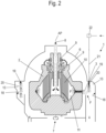
- FIG. 2 the openings, in particular nozzles, 19, which create the fluid curtain 20 in front of the baffle wall 18 of the solids catcher 13, are clearly shown.
- the solids catcher 13 here has a line with which the solids F is drained from the solids catcher 13. For this reason, the solids catcher 13 in the in Fig. 2
- the sectional view shown - where the section is placed through the derivation - has two different geometries.
- the starting product AP is preferably continuously fed into the drum 2 of the separator, where it is clarified. There is a continuous clear phase outlet of the clear phase KP.
- step 100 the emptying of the solid F from the solids collecting space 11 of the separator is initiated or, in the case of a continuously emptying separator 1, the separation process is started.
- step 200 the supply of fluid to the openings, in particular nozzles, 19 to generate the fluid curtain 20 in front of the baffle wall 18 of the solids catcher 13 is started by a control pulse on the actuator 22.
- a defined, discrete time interval elapses, which is determined according to the emptying duration and can be, for example, one to ten, particularly preferably three to five second(s).
- the fluid curtain is built.
- step 400 the emptying of the solid F from the solids collecting space 11 of the separator is started by a control pulse on the metering arrangement 16 and the valve arrangement 15, provided that the separator is a discontinuously emptying separator Fig. 1 acts.
- the emptying of the solid F begins immediately after the separation process has been started and the time interval in step 300 has elapsed.
- a subsequent step 500 the discharge of solid F from the solids collecting space 11 is ended by a control pulse on the metering arrangement 16 and the valve arrangement 15.
- the emptying of the solid F only ends when the separation process is ended.
- a final step 600 the supply of fluid to the openings, in particular nozzles, 19 for generating the fluid curtain 20 in front of the baffle wall 18 of the solids catcher 13 is ended by a control pulse on the actuator 22.
- the illustrated and claimed methods ensure gentle and low-shear emptying of solid F from a separator 1 according to the invention which discontinuously empties the solid F in a simple and therefore advantageous manner.
Landscapes
- Centrifugal Separators (AREA)
Description
- Die Erfindung betrifft eine Vorrichtung nach dem Oberbegriff des Anspruchs 1 und ein entsprechendes Verfahren.
- Selbstentleerende Separatoren werden zum Klären eines zu verarbeitenden Produktes von Stoffen mit höherem spezifischem Gewicht -im Folgenden Feststoffe genannt- verwendet und sind aus dem Stand der Technik bekannt. Danach weist ein solcher Separator eine drehbare Trommel mit einem Zulauf, wenigstens einen Flüssigkeitsauslass, diskontinuierlich zu öffnenden und zu verschließenden Feststoffauslassöffnungen oder kontinuierlich offenen Feststoffauslassöffnungen sowie eine Steuereinheit auf. Die Feststoffauslassöffnungen münden üblicherweise in einem Ringraum, der auch als Feststofffänger bezeichnet wird
- Bei der Verarbeitung von empfindlichen Produkten, wie z.B. Algen, Fermentationsbrühen oder anderen biogenen Produkten, muss evtl. verhindert werden, dass die auszugetragenen Feststoffe bei der Austragung aus dem Separator in den Feststofffänger auf Grund des starken Impulses, der auf den Feststoff wirkt, dauerhaft Schaden nehmen oder sogar in ihrer Struktur zerstört werden. Es ist in diesen Fällen also dafür Sorge zu tragen, dass die Kräfte, die beim Aufprall des Feststoffs auf eine Prallwand des Feststofffängers auf den Feststoff wirken, reduziert werden.
- In der
WO 03/008105 A1 - Ein gattungsgemäßer Separator nach dem Oberbegriff des Anspruchs 1 ist ferner aus der
DE 10 2013 111 576 A bekannt. - In der
US 3 145 172 A wird vorgeschlagen, mit tangential in einen Feststofffänger eingeleiteter Flüssigkeit den Feststofffänger zu säubern. - In der
DE 25 50 496 A1 und derDE 27 55 130 1 wird vorgeschlagen, bei einer Zuckerzentrifuge den Zucker nach dem Austragen aus der Schleudertrommel in Wasser aufzulösen. - Die Erfindung hat vor diesem Hintergrund die Aufgabe, den gattungsgemäßen selbstentleerenden Separator derart weiterzuentwickeln, dass mit ihm eine schonende und zerstörungsarme Feststoffaustragung möglich wird.
- Die Erfindung löst diese Aufgabe durch den Gegenstand des Anspruchs 1. Die Erfindung schafft ferner das Verfahren des Anspruchs 10.
- Demnach ist erfindungsgemäß vorgesehen, dass der Feststofffänger eine Einrichtung zur Erzeugung eines Fluidvorhanges aufweist, auf den die aus den Auslassöffnungen für Feststoff austretenden Feststoffe auftreffen, bevor sie im Feststofffänger auf eine feste Wand auftreffen könnten. Der Impuls des austretenden Feststoffs wird dadurch vorteilhaft zumindest teilweise beim Auftreffen auf den Fluidvorhang abgebaut, so dass der Feststoffaustrag in den Feststofffänger schonend und scherungsarm erfolgt. Entsprechend wird ein Verfahren zum Betreiben eines Separators nach einem der darauf bezogenen Ansprüche geschaffen, mit dem ein zu verarbeitendes Produkt in einem Zentrifugalfeld in der Trommel von Feststoff geklärt wird, der aus der Trommel kontinuierlich oder diskontinuierlich durch Auslassöffnungen entleert wird, und bei dem zumindest während der Entleerung der Feststoffe ein Fluidvorhang erzeugt wird, auf welchen die aus den Auslassöffnungen für Feststoffe austretenden Feststoffe auftreffen.
- Dabei weist die Einrichtung zur Erzeugung eines Fluidvorhanges Öffnungen, d.h. Düsen, auf, die am Umfang des Feststofffängers verteilt sind und mit denen der Fluidvorhang erzeugbar ist. Dadurch ist vorteilhaft gewährleistet, dass die benötigten Bauteile für einen schonenden und scherungsarmen Feststoffaustrag einfach und ohne Umbau des Feststofffängers an einen Separator angeordnet werden können oder sogar nachrüstbar sind. Der Fluidvorhang wird vorzugsweise derart erzeugt, dass er sich während des Feststoffaustrags zylindrisch oder konisch um die Trommel bzw. zumindest konzentrisch hülsenartig um deren Feststoffaustragsöffnungen erstreckt.
- In einer bevorzugten Ausführungsvariante weist der Feststofffänger eine Prallwand auf, die in Flugrichtung des Feststoffes hinter dem Vorhang angeordnet ist. Der Separator kann derart wahlweise mit oder ohne Fluidvorhang verwendet werden.
- Zweckmäßig ist, dass der Fluidvorhang entlang des gesamten Umfangs des Feststofffängers vor einer Prallwand ausgebildet ist.
- Der Fluidvorhang kann nach einer Variante an einem den Feststoff diskontinuierlich entleerenden Separator eingesetzt werden. Der Fluidvorhang ist eine vorteilhafte Ergänzung.
- In einer weiteren bevorzugten Ausführungsvariante der Erfindung kann als das Fluid, dass den Fluidvorhang ausbildet, Wasser verwendet werden. Der Fluidvorhang ist dann ein Wasservorhang aus flüssigem Wasser.
- Dies ist u.a. vorteilhaft, da eine Wasserhydraulik auch für eine Betätigung eines Kolbenschiebers vorhanden ist, der die Austragungsöffnungen eines Separators mit diskontinuierlichem Feststoffaustrag öffnet und schließt und da derart einfach ein weiterer Hydraulikteil zur Versorgung der Öffnungen, insbesondere Düsen, zur Erzeugung des Fluidvorhanges bereitgestellt werden kann.
- Auch die Verwendung des zu verarbeitenden Ausgangsproduktes oder dessen gewonnene Klarphase als Fluid für den Fluidvorhang ist vorteilhaft, da es hierdurch nicht zur Vermischung des Feststoffes mit einem zusätzlichen Fluid kommt.
- Um des ausgetragenen Feststoffes so wenig wie möglich zu verdünnen, kann der Fluidvorhang erst kurz vor der Entleerung eingeschaltet werden Zeitein <10 Sekunden beziehungsweise direkt nach der Entleerung wieder ausgeschaltet werden Zeitaus < 10 Sekunden.
- Falls es sich um einen Feststoff handelt, von dem keine Reste in dem Feststofffänger verbleiben sollen, kann der Wert für Zeitaus auch deutlich verlängert werden Zeitaus < 10 Minuten, um ein Ausspülen des Feststoffes aus dem Feststofffänger zu gewährleisten.
- Weitere vorteilhafte Ausgestaltungen des erfindungsgemäßen Separators sind den übrigen Unteransprüchen zu entnehmen.
- Die Erfindung wird nachfolgend anhand eines bevorzugten Ausführungsbeispiels unter Bezugnahme auf die beigefügten Zeichnungen näher erläutert. Es zeigt:
- Figur 1:
- eine schematische Schnittansicht eines erfindungsgemäßen selbstent-leerenden Separators mit diskontinuierlicher Feststoffaustragung;
- Figur 2:
- eine schematische Schnittansicht eines selbstentleerenden Separators mit kontinuierlicher Feststoffaustragung.
- Figur 3:
- ein schematischer Ablaufplan des erfindungsgemäßen Verfahrens.
-
Fig. 1 zeigt einen Separator 1 zum Klären von feststoffhaltigen, fließfähigen Ausgangsprodukten AP mit einer drehbaren Trommel 2 mit vertikaler Drehachse. Die Verarbeitung des Ausgangsproduktes AP erfolgt im kontinuierlichen Betrieb. Der Separator 1 ist ein selbstentleerender Separator 1. - Dies bedeutet, dass der Zulauf des Ausgangsprodukt AP kontinuierlich erfolgt und auch das Ableiten wenigstens einer geklärten Flüssigkeitsphase, Klarphase KP genannt, kontinuierlich erfolgt. Die Trommel 2 des Separators 1 verfügt in Ausgestaltung als selbstentleerender Separator 1 über einen hier diskontinuierlichen Feststoffauslass, wobei der aus dem Ausgangsprodukt AP durch Klärung abgetrennte Feststoff F hier intervallartig durch das Öffnen und Wiederverschließen von Auslassdüsen bzw. Auslassöffnungen 3 entfernt wird.
- Die Trommel 2 weist ein Trommelunterteil 4 und einen Trommeldeckel 5 auf. Sie ist ferner vorzugsweise von einer Haube 6 umgeben. Die Trommel 2 ist zudem auf eine Antriebsspindel 7 aufgesetzt, die drehbar gelagert und motorisch antreibbar ist.
- Die Trommel 2 weist einen Produktzulauf 8 auf, durch welchen das Ausgangsprodukt AP in die Trommel 2 geleitet wird. Sie weist ferner wenigstens einen Ablauf 9 - mit einem Greifer versehen - auf, der zur Ableitung einer Klarphase KP aus der Trommel 2 dient. Der Greifer - auch Schälscheibe genannt - ist eine Zentripetalpumpe. Der Ablauf 9 kann konstruktiv auch auf andere Weise bzw. mit anderen Mitteln erfolgen. Zudem ist es auch denkbar, neben der Klärung auch eine Trennung des Ausgangsproduktes AP in zwei Flüssigkeitsphasen verschiedener Dichte vorzunehmen. Hierzu ist dann ein weiterer Flüssigkeitsablauf erforderlich.
- Die Trommel 2 weist vorzugweise ein Tellerpaket 10 aus axial beabstandeten Trenntellern auf. Zwischen dem Außenumfang des Tellerpakets 10 und dem Innenumfang der Trommel 2 im Bereich ihres größten Innendurchmessers ist ein Feststoffsammelraum 11 ausgebildet. Feststoffe, welche im Bereich des Tellerpakets 10 von der Klarphase getrennt werden, sammeln sich in dem Feststoffsammelraum 11, aus dem die Feststoffe F über Auslassöffnungen 3 aus der Trommel 2 ausgetragen werden können.
- Die Auslassöffnungen 3 können dazu hier mittels eines Kolbenschiebers 12, welcher im Trommelunterteil 4 angeordnet ist und in diesem parallel zur Drehachse (insbesondere vertikal) verschiebbar ist, geöffnet und geschlossen werden. Bei geöffneten Auslassöffnungen 3 wird der Feststoff F aus der Trommel 2 in einen Feststofffänger 13 ausgelassen.
- Zur Bewegung des Kolbenschiebers 12 weist die Trommel 2 einen Betätigungsmechanismus auf. Hier umfasst dieser wenigstens eine Zulaufleitung 14 für ein Steuerfluid wie z.B. Wasser und eine Ventilanordnung 15 in der Trommel 2 und weitere Elemente außerhalb der Trommel 2. So wird der Zulauf des Steuerfluides über eine außerhalb der Trommel 2 angeordnete Dosieranordnung 16 ermöglicht, welche einer außerhalb der Trommel 2 angeordnete Zulaufleitung 17 für das Steuerfluid zugeordnet ist, so dass für eine Feststoffentleerung des Feststoffs F durch Freigabe der Ventilanordnung 15 das Steuerfluid in die Trommel 2 einleitbar ist oder umgekehrt der Zustrom an Steuerfluid unterbrochen werden kann, um den Kolbenschieber 12 entsprechend zu bewegen, um die Auslassöffnungen 3 freizugeben.
- Der Feststofffänger 13 weist eine Einrichtung zur Erzeugung eines Fluidvorhanges 20 auf, auf dem die aus den Auslassöffnungen 3 für Feststoff F austretenden Feststoffe F auftreffen.
- Der Feststofffänger 13 weist weiterhin wenigstens eine vorzugsweise bezogen auf die Drehachse radial äußere Prallwand 18 auf. Die Einrichtung zur Erzeugung eines Fluidvorhanges 20 weist mehrere, vorzugsweise vier oder mehr Öffnungen - insbesondere Düsen 19 - auf, die am Umfang des Feststofffängers 13 - vorzugsweise gleichmäßig - winkelbeabstandet verteilt sein können. Der Fluidvorhang 20 liegt bezogen auf die Prallwand 18 radial innen.
- Dabei ist die Anzahl der Öffnungen, insbesondere Düsen, 19 abhängig vom Durchmesser der Trommel 2 und wird vorteilhaft so gewählt, dass durch die Öffnungen, insbesondere Düsen, 19 der Fluidvorhang 20 so erzeugt wird, dass er vorteilhaft entlang des gesamten Umfangs des Feststofffängers 13 vor seiner Prallwand 18 ausgebildet ist. Der Impuls des austretenden Feststoffs F wird dadurch vorteilhaft zumindest teilweise beim Auftreffen auf den Fluidvorhang 20 abgebaut.
- Der Fluidvorhang 20 wird vorzugsweise in axialer Richtung bei vertikaler Drehachse von oben nach unten gesprüht. Dann sind die Öffnungen 19 vorzugsweise an einer oberen Wandung des Feststofffängers oder an einem angrenzenden Bauteil wie einer Haube verteilt und ihr Austrittsende ist vorzugsweise axial im Wesentlichen nach unten gerichtet. Vorzugsweise ist der Fluidvorhang 20 in erzeugten Zustand zylindrisch oder konisch. Er kann aber z.B. auch umfangsgeschlossen mehreckig die Trommel umgeben. Dazu sind die Öffnungen 19 vorzugsweise an einer oberen Wandung des Feststofffängers verteilt und ihr Austrittsende ist nach unten gerichtet.
- Die Öffnungen, insbesondere Düsen, 19 sind vorzugsweise so gestaltet, dass das austretende Fluid fächerartig austritt, d.h. radial bezogen auf die Drehachse der Trommel ist der Fluidstrahl schmal, senkrecht dazu ist der Fluidstrahl breit, um mit möglichst wenig Öffnungen, insbesondere Düsen, den gesamten Umfang innerhalb des Feststofffängers mit einem Fluidvorhang 20 abzudecken. Um diesen fächerartigen Austritt zu erzeugen, kann die Düse mit einer schlitzartigen Austrittsöffnung versehen werden oder alternativ mit mehreren Austrittsöffnungen in Richtung des zu erzeugenden Fluidvorhanges.
- Die Wirksamkeit des Fluidvorhanges kann durch die Menge/Zeit des eingesetzten Fluides in Abhängigkeit von der Empfindlichkeit des zu verarbeitenden Produktes eingestellt werden. Je mehr Fluid eingesetzt wird, desto dichter wird der Fluidvorhang und desto stärker wird der Impuls des austretenden Feststoffes abgebaut. Hierzu kann im Stellglied 22 die Menge/Zeit des Fluides geregelt werden indem hierin der Öffnungsquerschnitt eines Ventils verändert wird. Alternativ kann der Druck des Fluids in der Leitung 21 verändert werden, oder auch die Querschnitte der Öffnungen in den Öffnungen, insbesondere Düsen, 19 angepasst werden.
- Die Öffnungen, insbesondere Düsen, 19 können, wie in
Fig. 1 undFig. 2 dargestellt, das Fluid von oben in den Feststofffänger leiten, alternativ ist dies auch von unten möglich oder auch tangential aus Richtung der Prallwand 18. - Das den Fluidvorhang 20 bildende Fluid ist vorzugsweise Wasser. Dies ist vorteilhaft, da eine Wasserhydraulik auch für die Betätigung des Kolbenschiebers 12 vorhanden sein kann und insofern Teile dieser Hydraulik mehrfach nutzbar sind. Dies ist jedoch nicht zwingend.
- Alternativ/Optional ist auch die Verwendung des zu verarbeitenden Ausgangsproduktes oder dessen gewonnene Klarphase als Fluid für den Fluidvorhang vorteilhaft, da es hierdurch nicht zur Vermischung des Feststoffes mit einem zusätzlichen Fluid kommt.
- Die Zuführung des Fluids erfolgt über eine entsprechende Leitung 21. Die Leitung 21 kann durch einen Steuerimpuls durch ein Stellglied 22 abgesperrt und geöffnet werden.
- Um den ausgetragenen Feststoff so wenig wie möglich zu verdünnen, kann der Fluidvorhang 20 erst kurz vor der Entleerung des Feststoffes eingeschaltet werden. So kann die Einschaltzeit vor der Entleerung "Zeitein <10 Sekunden" betragen. Der Fluidvorhang wird vorzugsweise direkt nach der Entleerung wieder ausgeschaltet.
- Vorzugsweise gilt: "Zeitaus < 10 Sekunden", da der Fluidvorhang bis zur nächsten Entleerung nicht weiter benötigt wird.
- Falls es sich um einen Feststoff handelt, von dem keine Reste in dem Feststofffänger verbleiben sollen, kann der Wert für Zeitaus auch deutlich verlängert werden Zeitaus < 10 Minuten, um ein Ausspülen des Feststoffes aus dem Feststofffänger zu gewährleisten.
- Wenn es sich als vorteilhaft für das Ausleiten der Feststoffe aus dem Feststofffänger erweist, z.B. bei klebrigen oder adhäsiven Feststoffen, kann der Fluidvorhang auch dauerhaft aktiviert sein.
- Durch den sich vor der Prallwand 18 erstreckende Fluidvorhang 20 wird einfach vorteilhaft ein schonender und scherungsarmer Impulsabbau des aus den Auslassöffnungen 3 des Separators 1 in den Feststofffänger 13 austretenden Feststoffs F ermöglicht.
- Vorteilhaft ist ferner, dass die dazu benötigten Bauteile 19, 21, 22 einfach und ohne Umbau des Feststofffängers 13 an einen Separator 1 nachrüstbar sind. Darüber hinaus wird das konstruktive Variantenmanagement des Separators 1 vereinfacht, da die Variante des Feststofffängers 13 für einen schonenden Feststoffaustrag einfach und damit vorteilhaft durch die gewöhnliche Variante des Feststofffängers 13 plus die Öffnungen, insbesondere Düsen, 19 gebildet ist.
- Dier hier geschilderten Steuerungsvorgänge bzw. Steuerimpulse werden durch eine Steuerungsvorrichtung 23 gesteuert bzw. koordiniert. Die Steuerungsvorrichtung 23 ist dazu über Datenverbindungen 24, 25, die hier beispielhaft durch spannungsführende bzw. signalführende Leitungen bzw. Kabel ausgeführt sind, mit den Stellgliedern bzw. Ventilen 16, 21 verbunden. Die Datenverbindungen 24, 25 können alternativ aus durch andere geeignete Wirkprinzipien, wie z.B. durch das Überbrücken der Signalstrecke durch hochfrequente Strahlung, wie z.B. Funksignale realisiert sein.
- Um Wiederholungen zu vermeiden, werden zu dem Separator 1 in
Fig. 2 nur Abweichungen, Änderungen oder Ergänzungen zu dem Separator 1 nachFig. 1 beschrieben. - Abweichend zu dem Separator 1 nach
Fig. 1 , arbeitet der Separator 1 nachFig. 2 , der nicht unter Anspruch 1 fällt, als selbstentleerender Separator 1 mit einem kontinuierlichen Feststoffauslass. Demzufolge verfügt die Trommel 2 des Separators 1 hier über einen kontinuierlichen Feststoffauslass, wobei der aus dem Ausgangsprodukt AP durch Klärung abgetrennte Feststoff F hier permanent durch die Auslassdüsen bzw. Auslassöffnungen 3 entfernt wird. Ein Kolbenschieber 12 mit den entsprechenden Stellgliedern und Zuleitungen ist demzufolge hier nicht erforderlich. - In
Fig. 2 sind die Öffnungen, insbesondere Düsen, 19, die den Fluidvorhang 20 vor der Prallwand 18 des Feststofffängers 13 erzeugen, gut sichtbar dargestellt. Der Feststofffänger 13 weist hier eine Leitung auf, mit der der Feststoff F aus dem Feststofffänger 13 abgeleitet wird. Aus diesem Grund weist der Feststofffänger 13 in der inFig. 2 gezeigten Schnittdarstellung - wobei der Schnitt durch die Ableitung gelegt ist - zwei unterschiedliche Geometrien auf. - Nachfolgend wird ein Ausführungsbeispiel eines Produkt-Klärverfahrens, welches mit dem vorbeschriebenen Separator 1 durchgeführt werden kann, anhand der Figuren näher erläutert.
- In die Trommel 2 des Separators wird vorzugsweise kontinuierlich das Ausgangsprodukt AP geleitet, wo dieses geklärt wird. Es erfolgt ein kontinuierlicher Klarphasenauslass der Klarphase KP.
- Während der Klärung des Ausgangsproduktes AP unter Bildung der Klarphase KP werden im Ausgangsprodukt AP enthaltene Trubstoffe und andere Feststoffe F im Feststoffsammelraum 11 der Trommel 2 außerhalb des Tellerpaketes 10 gesammelt, der sich füllt.
- Bei einem diskontinuierlich entleerenden Separator 1 wird in Abhängigkeit von definierten Parametern die Austragung des Feststoffs F aus der Trommel 2 durch die Auslassöffnungen 3 in den Feststofffänger 13 initiiert, während bei einem kontinuierlich entleerenden Separator 1 die Austragung von Feststoff F permanent nach Starten des Separationsprozesses geschieht.
- Für das schonende und scherungsarme Entleeren von Feststoff F aus einem erfindungsgemäßen, den Feststoff F diskontinuierlich oder kontinuierlich entleerenden Separator 1 wird folgendes Verfahren angegeben:
Das Verfahren - sieheFig. 3 - startet im Schritt 100. In Schritt 100 wird die Entleerung des Feststoffs F aus dem Feststoffsammelraum 11 des Separators initiiert bzw. bei einem kontinuierlich entleerenden Separator 1 wird der Separationsprozess in Gang gesetzt. - Danach wird in einem weiteren Schritt 200 durch einen Steuerimpuls auf das Stellglied 22 die Zufuhr von Fluid zu den Öffnungen, insbesondere Düsen, 19 zur Erzeugung des Fluidvorhangs 20 vor der Prallwand 18 des Feststofffängers 13 gestartet.
- In einem darauf folgenden Schritt 300 verstreicht ein definierter, diskreter Zeitintervall, der entsprechend der Entleerungsdauer bestimmt wird und z.B. eine bis zehn, besonders bevorzugt drei bis fünf Sekunde(n) betragen kann. Der Fluidvorhang wird aufgebaut.
- In einem weiteren Schritt 400 wird die Entleerung des Feststoffs F aus dem Feststoffsammelraum 11 des Separators durch einen Steuerimpuls auf die Dosieranordnung 16 und die Ventilanordnung 15 gestartet, sofern es sich bei dem Separator um einen diskontinuierlich entleerenden Separator nach
Fig. 1 handelt. Bei einem kontinuierlich entleerenden Separator beginnt die Entleerung des Feststoffs F nach dem der Separationsprozess gestartet wurde und das Zeitintervall in Schritt 300 verstrichen ist, direkt. - In einem darauf folgenden Schritt 500 wird die Austragung von Feststoff F aus dem Feststoffsammelraum 11 durch einen Steuerimpuls auf die Dosieranordnung 16 und die Ventilanordnung 15 beendet. Bei einem kontinuierlich entleerenden Separator endet die Entleerung des Feststoffs F erst, wenn der Trennprozess beendet wird.
- In einem abschließenden Schritt 600 wird die Zufuhr von Fluid zu den Öffnungen, insbesondere Düsen, 19 zur Erzeugung des Fluidvorhangs 20 vor der Prallwand 18 des Feststofffängers 13 durch einen Steuerimpuls auf das Stellglied 22 beendet.
- Insgesamt wird mit den dargestellten und beanspruchten Verfahren auf einfache und damit vorteilhafte Weise ein schonendes und scherungsarmes Entleeren von Feststoff F aus einem erfindungsgemäßen, den Feststoff F diskontinuierlich entleerenden Separator 1 gewährleistet.
-
- 1
- Separator
- 2
- Trommel
- 3
- Auslassöffnung
- 4
- Trommelunterteil
- 5
- Trommeldeckel
- 6
- Haube
- 7
- Spindel
- 8
- Zulauf
- 9
- Ablauf
- 10
- Tellerpaket
- 11
- Feststoffsammelraum
- 12
- Kolbenschieber
- 13
- Feststofffänger
- 14
- Zulaufleitung
- 15
- Ventilanordnung
- 16
- Dosieranordnung
- 17
- Hydraulikleitung
- 18
- Prallwand
- 19
- Öffnung
- 20
- Fluidvorhang
- 21
- Zuleitung
- 22
- Stellglied
- 23
- Steuerung
- 24
- Datenverbindung
- 25
- Datenverbindung
- KP
- Klarphase
- AP
- Ausgangsprodukt
- F
- Feststoff
Claims (10)
- Selbstentleerender Separator (1), der eine drehbare Trommel (2) mit einem Zulauf (8), mit wenigstens einem Flüssigkeitsablauf (9) mit Auslassöffnungen (3) für Feststoff (F) und eine Steuerung (23) aufweist, in dem ein fließfähiges Ausgangsprodukt (AP) in einem kontinuierlichen Betrieb in einem Zentrifugalfeld in der sich drehenden Trommel (2) von den Feststoffen (F) geklärt wird, wobei ein kontinuierliches Auslassen wenigstens einer geklärten Flüssigkeitsphase - einer Klarphase (KP) - erfolgt und wobei mit den Auslassöffnungen (3) ein Auslassen einer Feststoffphase (F) - Feststoffentleerung genannt -, aus einem Feststoffsammelraum (11) der Trommel (2) in einen ringförmigen Feststofffänger (13) diskontinuierlich erfolgt, so dass der Separator (1) ein den Feststoff (F) diskontinuierlich entleerender Separator (1) ist,
dadurch gekennzeichnet, dass
der Feststofffänger (13) eine Einrichtung zur Erzeugung eines Fluidvorhanges (20) aufweist, auf welchen die aus den Auslassöffnungen (3) für Feststoff (F) austretenden Feststoffe (F) auftreffen, wobei die Einrichtung zur Erzeugung eines Fluidvorhanges (20) Öffnungen aufweist, wobei die Öffnungen (19) an einer oberen Wandung des Feststofffängers oder an einem angrenzenden Bauteil wie einer Haube verteilt sind und ihr Austrittsende axial im Wesentlichen nach unten gerichtet ist, wobei die Öffnungen Düsen (19) sind und wobei die Düsen (19) am Umfang der Feststofffängers (13) verteilt sind. - Selbstentleerender Separator (1) nach Anspruch 1, dadurch gekennzeichnet, dass mindestens vier oder mehr Öffnungen, insbesondere Düsen, (19) am Umfang des Feststofffängers (13) verteilt sind.
- Selbstentleerender Separator (1) nach einem der vorgenannten Ansprüche, dadurch gekennzeichnet, dass der Feststofffänger (13) eine Prallwand (18) aufweist.
- Selbstentleerender Separator (1) nach einem der vorgenannten Ansprüche, dadurch gekennzeichnet, dass der Fluidvorhang (20) entlang des gesamten Umfangs des Feststofffängers (13) vor seiner Prallwand (18) ausgebildet ist.
- Selbstentleerender Separator (1) nach einem der Ansprüche 1 bis 4, dadurch gekennzeichnet, dass der Separator (1) ein den Feststoff (F) kontinuierlich entleerender Separator (1) ist.
- Selbstentleerender Separator (1) nach einem der vorgenannten Ansprüche, dadurch gekennzeichnet, dass das Fluid, dass den Fluidvorhang (20) ausbildet, Wasser ist.
- Selbstentleerender Separator (1) nach einem der vorgenannten Ansprüche, dadurch gekennzeichnet, dass als das Fluid, das den Fluidvorhang (20) ausbildet, das Ausgangsprodukt oder die oder eine der aus dem zu verarbeitenden Ausgangsprodukt gewonnene(n) Klarphase(n) verwendet wird.
- Selbstentleerender Separator (1) nach einem der vorgenannten Ansprüche, dadurch gekennzeichnet, dass die Zuführung des Fluids zu den Öffnungen, insbesondere Düsen, (19) über eine Zuleitung (21) erfolgt, wobei die Zuleitung (21) durch ein Stellglied (22) absperrbar und öffenbar ist.
- Selbstentleerender Separator (1) nach einem der vorstehenden Ansprüche, dadurch gekennzeichnet, dass eine Steuerungsvorrichtung (23) vorgesehen ist, die vorzugsweise über Datenverbindungen (24, 25) mit dem Stellglied (22) verbunden ist.
- Verfahren zum Betreiben eines Separators nach einem der vorstehenden Ansprüche, mit dem ein zu verarbeitendes Produkt in einem Zentrifugalfeld in der Trommel von Feststoff geklärt wird, der aus der Trommel diskontinuierlich entleert wird, dadurch gekennzeichnet, dass zumindest während der Entleerung der Feststoffe ein Fluidvorhang erzeugt wird, auf welchen die aus den Auslassöffnungen (3) für Feststoff (F) austretenden Feststoffe (F) auftreffen.
Applications Claiming Priority (2)
| Application Number | Priority Date | Filing Date | Title |
|---|---|---|---|
| DE102017106801.5A DE102017106801B3 (de) | 2017-03-29 | 2017-03-29 | Selbstentleerender Separator zum schonenden Austrag von scherempfindlichen Produkten sowie Verfahren zu seinem Betrieb |
| PCT/EP2018/055726 WO2018177710A1 (de) | 2017-03-29 | 2018-03-08 | Selbstentleerender separator zum schonenden austrag von scherempfindlichen produkten sowie verfahren zu seinem betrieb |
Publications (2)
| Publication Number | Publication Date |
|---|---|
| EP3600679A1 EP3600679A1 (de) | 2020-02-05 |
| EP3600679B1 true EP3600679B1 (de) | 2023-09-13 |
Family
ID=61622584
Family Applications (1)
| Application Number | Title | Priority Date | Filing Date |
|---|---|---|---|
| EP18710435.1A Active EP3600679B1 (de) | 2017-03-29 | 2018-03-08 | Selbstentleerender separator zum schonenden austrag von scherempfindlichen produkten sowie verfahren zu seinem betrieb |
Country Status (5)
| Country | Link |
|---|---|
| US (1) | US11389809B2 (de) |
| EP (1) | EP3600679B1 (de) |
| CN (1) | CN110520220B (de) |
| DE (1) | DE102017106801B3 (de) |
| WO (1) | WO2018177710A1 (de) |
Families Citing this family (2)
| Publication number | Priority date | Publication date | Assignee | Title |
|---|---|---|---|---|
| TWI697353B (zh) * | 2019-08-07 | 2020-07-01 | 長泰精密有限公司 | 油水分離機分離筒上蓋裝置 |
| DE102020128748A1 (de) * | 2020-11-02 | 2022-05-05 | Gea Westfalia Separator Group Gmbh | Separator |
Family Cites Families (6)
| Publication number | Priority date | Publication date | Assignee | Title |
|---|---|---|---|---|
| US3145172A (en) * | 1959-07-09 | 1964-08-18 | Separator Ab | Flushing device for centrifugal separators |
| DE2550496B2 (de) * | 1975-11-11 | 1980-12-04 | Braunschweigische Maschinenbauanstalt, 3300 Braunschweig | Verfahren und Zentrifuge zum Abschleudern und Wiederauflösen von Zucker |
| DE2755130A1 (de) * | 1977-12-10 | 1979-06-13 | Selwig & Lange Maschf | Verfahren und vorrichtung zum einmaischen von zuckerkristallen |
| SE509400C2 (sv) * | 1996-01-02 | 1999-01-25 | Noxon Ab | Dekanteringscentrifug |
| DE10135317A1 (de) | 2001-07-19 | 2003-01-30 | Bayer Ag | Umlenkring für eine selbstaustragende Zentrifuge |
| DE102013111576A1 (de) * | 2013-10-21 | 2015-04-23 | Gea Mechanical Equipment Gmbh | Verfahren zur Klärung eines fließfähigen Produktes mit einer Zentrifuge, insbesondere einem Separator |
-
2017
- 2017-03-29 DE DE102017106801.5A patent/DE102017106801B3/de active Active
-
2018
- 2018-03-08 WO PCT/EP2018/055726 patent/WO2018177710A1/de not_active Ceased
- 2018-03-08 EP EP18710435.1A patent/EP3600679B1/de active Active
- 2018-03-08 CN CN201880021958.5A patent/CN110520220B/zh active Active
- 2018-03-08 US US16/498,540 patent/US11389809B2/en active Active
Also Published As
| Publication number | Publication date |
|---|---|
| DE102017106801B3 (de) | 2018-08-02 |
| CN110520220B (zh) | 2022-01-14 |
| EP3600679A1 (de) | 2020-02-05 |
| US20200038882A1 (en) | 2020-02-06 |
| US11389809B2 (en) | 2022-07-19 |
| CN110520220A (zh) | 2019-11-29 |
| WO2018177710A1 (de) | 2018-10-04 |
Similar Documents
| Publication | Publication Date | Title |
|---|---|---|
| EP3426405B1 (de) | Separator | |
| EP3930909B1 (de) | Separator | |
| DE19907067C2 (de) | Trennvorrichtung für das Aussondern von Feststoffen aus einem Flüssigkeits-Feststoff-Gemisch | |
| EP2484451A2 (de) | Vollmantelzentrifuge mit Trocknung des Feststoffkuchens | |
| DE10340366B4 (de) | Filtervorrichtung | |
| DE102017106801B3 (de) | Selbstentleerender Separator zum schonenden Austrag von scherempfindlichen Produkten sowie Verfahren zu seinem Betrieb | |
| WO2007074076A1 (de) | Vollmantel-schneckenzentrifuge | |
| EP3328550A1 (de) | Separatortrommel und separator | |
| WO2016034626A1 (de) | Separator und verfahren zum abtrennen von partikeln aus einem gasstrom | |
| WO2018224400A1 (de) | Verfahren zur feststoffentleerung einer zentrifuge | |
| EP0927579A2 (de) | Vorrichtung und Verfahren zum Entfernen von Feststoffen aus einem Feststoff-Flüssigkeitsgemisch | |
| WO2007104455A1 (de) | Zentrifuge mit einem einlaufrohr | |
| EP4237157B1 (de) | Separator | |
| DE10200599A1 (de) | Vorrichtung zum Abscheiden von organischem und anorganischem Material aus einer Flüssigkeit | |
| DE202010005476U1 (de) | Separator | |
| EP3570981B1 (de) | Zentrifuge | |
| EP0692311B1 (de) | Kontinuierlich arbeitende Zentrifuge zum Abschleudern von Zuckerfüllmassen | |
| EP4475996B1 (de) | Separator | |
| DE102008009253A1 (de) | Schälvorrichtung zum Abschälen eines Feststoffkuchenmaterials von der Innenseite einer Trommel einer Zentrifuge | |
| DE102010016740B4 (de) | Düsenseparator und Verfahren zum Ableiten einer Feststoffphase aus dem Düsenseparator | |
| WO2010007057A1 (de) | Vorrichtung und verfahren zum entfernen von fluiden und/oder feststoffen | |
| DE102022124097A1 (de) | Verfahren zur Reinigung eines Separators | |
| WO2021121454A1 (de) | Verfahren zum reinigen von gebrauchtem waschwasser und reinigungsvorrichtung zur durchführung des verfahrens | |
| DE3044797A1 (de) | Verfahren und vorrichtung zum mechanischen trennen von feststoffteilen aus fluessigkeiten durch zentrifugieren | |
| DE2013865A1 (de) | Zentrifuge |
Legal Events
| Date | Code | Title | Description |
|---|---|---|---|
| STAA | Information on the status of an ep patent application or granted ep patent |
Free format text: STATUS: UNKNOWN |
|
| STAA | Information on the status of an ep patent application or granted ep patent |
Free format text: STATUS: THE INTERNATIONAL PUBLICATION HAS BEEN MADE |
|
| PUAI | Public reference made under article 153(3) epc to a published international application that has entered the european phase |
Free format text: ORIGINAL CODE: 0009012 |
|
| STAA | Information on the status of an ep patent application or granted ep patent |
Free format text: STATUS: REQUEST FOR EXAMINATION WAS MADE |
|
| 17P | Request for examination filed |
Effective date: 20191002 |
|
| AK | Designated contracting states |
Kind code of ref document: A1 Designated state(s): AL AT BE BG CH CY CZ DE DK EE ES FI FR GB GR HR HU IE IS IT LI LT LU LV MC MK MT NL NO PL PT RO RS SE SI SK SM TR |
|
| AX | Request for extension of the european patent |
Extension state: BA ME |
|
| DAV | Request for validation of the european patent (deleted) | ||
| DAX | Request for extension of the european patent (deleted) | ||
| GRAP | Despatch of communication of intention to grant a patent |
Free format text: ORIGINAL CODE: EPIDOSNIGR1 |
|
| STAA | Information on the status of an ep patent application or granted ep patent |
Free format text: STATUS: GRANT OF PATENT IS INTENDED |
|
| INTG | Intention to grant announced |
Effective date: 20230406 |
|
| GRAJ | Information related to disapproval of communication of intention to grant by the applicant or resumption of examination proceedings by the epo deleted |
Free format text: ORIGINAL CODE: EPIDOSDIGR1 |
|
| STAA | Information on the status of an ep patent application or granted ep patent |
Free format text: STATUS: REQUEST FOR EXAMINATION WAS MADE |
|
| GRAS | Grant fee paid |
Free format text: ORIGINAL CODE: EPIDOSNIGR3 |
|
| STAA | Information on the status of an ep patent application or granted ep patent |
Free format text: STATUS: GRANT OF PATENT IS INTENDED |
|
| GRAP | Despatch of communication of intention to grant a patent |
Free format text: ORIGINAL CODE: EPIDOSNIGR1 |
|
| GRAA | (expected) grant |
Free format text: ORIGINAL CODE: 0009210 |
|
| STAA | Information on the status of an ep patent application or granted ep patent |
Free format text: STATUS: THE PATENT HAS BEEN GRANTED |
|
| INTG | Intention to grant announced |
Effective date: 20230803 |
|
| AK | Designated contracting states |
Kind code of ref document: B1 Designated state(s): AL AT BE BG CH CY CZ DE DK EE ES FI FR GB GR HR HU IE IS IT LI LT LU LV MC MK MT NL NO PL PT RO RS SE SI SK SM TR |
|
| P01 | Opt-out of the competence of the unified patent court (upc) registered |
Effective date: 20230809 |
|
| REG | Reference to a national code |
Ref country code: GB Ref legal event code: FG4D Free format text: NOT ENGLISH |
|
| REG | Reference to a national code |
Ref country code: CH Ref legal event code: EP |
|
| REG | Reference to a national code |
Ref country code: DE Ref legal event code: R096 Ref document number: 502018013246 Country of ref document: DE |
|
| REG | Reference to a national code |
Ref country code: IE Ref legal event code: FG4D Free format text: LANGUAGE OF EP DOCUMENT: GERMAN |
|
| REG | Reference to a national code |
Ref country code: SE Ref legal event code: TRGR |
|
| REG | Reference to a national code |
Ref country code: LT Ref legal event code: MG9D |
|
| REG | Reference to a national code |
Ref country code: NL Ref legal event code: MP Effective date: 20230913 |
|
| PG25 | Lapsed in a contracting state [announced via postgrant information from national office to epo] |
Ref country code: GR Free format text: LAPSE BECAUSE OF FAILURE TO SUBMIT A TRANSLATION OF THE DESCRIPTION OR TO PAY THE FEE WITHIN THE PRESCRIBED TIME-LIMIT Effective date: 20231214 |
|
| PG25 | Lapsed in a contracting state [announced via postgrant information from national office to epo] |
Ref country code: RS Free format text: LAPSE BECAUSE OF FAILURE TO SUBMIT A TRANSLATION OF THE DESCRIPTION OR TO PAY THE FEE WITHIN THE PRESCRIBED TIME-LIMIT Effective date: 20230913 Ref country code: NO Free format text: LAPSE BECAUSE OF FAILURE TO SUBMIT A TRANSLATION OF THE DESCRIPTION OR TO PAY THE FEE WITHIN THE PRESCRIBED TIME-LIMIT Effective date: 20231213 Ref country code: LV Free format text: LAPSE BECAUSE OF FAILURE TO SUBMIT A TRANSLATION OF THE DESCRIPTION OR TO PAY THE FEE WITHIN THE PRESCRIBED TIME-LIMIT Effective date: 20230913 Ref country code: LT Free format text: LAPSE BECAUSE OF FAILURE TO SUBMIT A TRANSLATION OF THE DESCRIPTION OR TO PAY THE FEE WITHIN THE PRESCRIBED TIME-LIMIT Effective date: 20230913 Ref country code: HR Free format text: LAPSE BECAUSE OF FAILURE TO SUBMIT A TRANSLATION OF THE DESCRIPTION OR TO PAY THE FEE WITHIN THE PRESCRIBED TIME-LIMIT Effective date: 20230913 Ref country code: GR Free format text: LAPSE BECAUSE OF FAILURE TO SUBMIT A TRANSLATION OF THE DESCRIPTION OR TO PAY THE FEE WITHIN THE PRESCRIBED TIME-LIMIT Effective date: 20231214 Ref country code: FI Free format text: LAPSE BECAUSE OF FAILURE TO SUBMIT A TRANSLATION OF THE DESCRIPTION OR TO PAY THE FEE WITHIN THE PRESCRIBED TIME-LIMIT Effective date: 20230913 |
|
| PG25 | Lapsed in a contracting state [announced via postgrant information from national office to epo] |
Ref country code: NL Free format text: LAPSE BECAUSE OF FAILURE TO SUBMIT A TRANSLATION OF THE DESCRIPTION OR TO PAY THE FEE WITHIN THE PRESCRIBED TIME-LIMIT Effective date: 20230913 |
|
| PG25 | Lapsed in a contracting state [announced via postgrant information from national office to epo] |
Ref country code: IS Free format text: LAPSE BECAUSE OF FAILURE TO SUBMIT A TRANSLATION OF THE DESCRIPTION OR TO PAY THE FEE WITHIN THE PRESCRIBED TIME-LIMIT Effective date: 20240113 |
|
| PG25 | Lapsed in a contracting state [announced via postgrant information from national office to epo] |
Ref country code: ES Free format text: LAPSE BECAUSE OF FAILURE TO SUBMIT A TRANSLATION OF THE DESCRIPTION OR TO PAY THE FEE WITHIN THE PRESCRIBED TIME-LIMIT Effective date: 20230913 |
|
| PG25 | Lapsed in a contracting state [announced via postgrant information from national office to epo] |
Ref country code: SM Free format text: LAPSE BECAUSE OF FAILURE TO SUBMIT A TRANSLATION OF THE DESCRIPTION OR TO PAY THE FEE WITHIN THE PRESCRIBED TIME-LIMIT Effective date: 20230913 Ref country code: RO Free format text: LAPSE BECAUSE OF FAILURE TO SUBMIT A TRANSLATION OF THE DESCRIPTION OR TO PAY THE FEE WITHIN THE PRESCRIBED TIME-LIMIT Effective date: 20230913 Ref country code: IS Free format text: LAPSE BECAUSE OF FAILURE TO SUBMIT A TRANSLATION OF THE DESCRIPTION OR TO PAY THE FEE WITHIN THE PRESCRIBED TIME-LIMIT Effective date: 20240113 Ref country code: ES Free format text: LAPSE BECAUSE OF FAILURE TO SUBMIT A TRANSLATION OF THE DESCRIPTION OR TO PAY THE FEE WITHIN THE PRESCRIBED TIME-LIMIT Effective date: 20230913 Ref country code: EE Free format text: LAPSE BECAUSE OF FAILURE TO SUBMIT A TRANSLATION OF THE DESCRIPTION OR TO PAY THE FEE WITHIN THE PRESCRIBED TIME-LIMIT Effective date: 20230913 Ref country code: CZ Free format text: LAPSE BECAUSE OF FAILURE TO SUBMIT A TRANSLATION OF THE DESCRIPTION OR TO PAY THE FEE WITHIN THE PRESCRIBED TIME-LIMIT Effective date: 20230913 Ref country code: PT Free format text: LAPSE BECAUSE OF FAILURE TO SUBMIT A TRANSLATION OF THE DESCRIPTION OR TO PAY THE FEE WITHIN THE PRESCRIBED TIME-LIMIT Effective date: 20240115 Ref country code: SK Free format text: LAPSE BECAUSE OF FAILURE TO SUBMIT A TRANSLATION OF THE DESCRIPTION OR TO PAY THE FEE WITHIN THE PRESCRIBED TIME-LIMIT Effective date: 20230913 |
|
| PG25 | Lapsed in a contracting state [announced via postgrant information from national office to epo] |
Ref country code: PL Free format text: LAPSE BECAUSE OF FAILURE TO SUBMIT A TRANSLATION OF THE DESCRIPTION OR TO PAY THE FEE WITHIN THE PRESCRIBED TIME-LIMIT Effective date: 20230913 |
|
| REG | Reference to a national code |
Ref country code: DE Ref legal event code: R097 Ref document number: 502018013246 Country of ref document: DE |
|
| PG25 | Lapsed in a contracting state [announced via postgrant information from national office to epo] |
Ref country code: DK Free format text: LAPSE BECAUSE OF FAILURE TO SUBMIT A TRANSLATION OF THE DESCRIPTION OR TO PAY THE FEE WITHIN THE PRESCRIBED TIME-LIMIT Effective date: 20230913 |
|
| PLBE | No opposition filed within time limit |
Free format text: ORIGINAL CODE: 0009261 |
|
| STAA | Information on the status of an ep patent application or granted ep patent |
Free format text: STATUS: NO OPPOSITION FILED WITHIN TIME LIMIT |
|
| PG25 | Lapsed in a contracting state [announced via postgrant information from national office to epo] |
Ref country code: DK Free format text: LAPSE BECAUSE OF FAILURE TO SUBMIT A TRANSLATION OF THE DESCRIPTION OR TO PAY THE FEE WITHIN THE PRESCRIBED TIME-LIMIT Effective date: 20230913 |
|
| 26N | No opposition filed |
Effective date: 20240614 |
|
| PG25 | Lapsed in a contracting state [announced via postgrant information from national office to epo] |
Ref country code: SI Free format text: LAPSE BECAUSE OF FAILURE TO SUBMIT A TRANSLATION OF THE DESCRIPTION OR TO PAY THE FEE WITHIN THE PRESCRIBED TIME-LIMIT Effective date: 20230913 |
|
| PG25 | Lapsed in a contracting state [announced via postgrant information from national office to epo] |
Ref country code: SI Free format text: LAPSE BECAUSE OF FAILURE TO SUBMIT A TRANSLATION OF THE DESCRIPTION OR TO PAY THE FEE WITHIN THE PRESCRIBED TIME-LIMIT Effective date: 20230913 |
|
| REG | Reference to a national code |
Ref country code: CH Ref legal event code: PL |
|
| PG25 | Lapsed in a contracting state [announced via postgrant information from national office to epo] |
Ref country code: BG Free format text: LAPSE BECAUSE OF FAILURE TO SUBMIT A TRANSLATION OF THE DESCRIPTION OR TO PAY THE FEE WITHIN THE PRESCRIBED TIME-LIMIT Effective date: 20230913 |
|
| PG25 | Lapsed in a contracting state [announced via postgrant information from national office to epo] |
Ref country code: LU Free format text: LAPSE BECAUSE OF NON-PAYMENT OF DUE FEES Effective date: 20240308 |
|
| PG25 | Lapsed in a contracting state [announced via postgrant information from national office to epo] |
Ref country code: MC Free format text: LAPSE BECAUSE OF FAILURE TO SUBMIT A TRANSLATION OF THE DESCRIPTION OR TO PAY THE FEE WITHIN THE PRESCRIBED TIME-LIMIT Effective date: 20230913 |
|
| GBPC | Gb: european patent ceased through non-payment of renewal fee |
Effective date: 20240308 |
|
| PG25 | Lapsed in a contracting state [announced via postgrant information from national office to epo] |
Ref country code: MC Free format text: LAPSE BECAUSE OF FAILURE TO SUBMIT A TRANSLATION OF THE DESCRIPTION OR TO PAY THE FEE WITHIN THE PRESCRIBED TIME-LIMIT Effective date: 20230913 Ref country code: LU Free format text: LAPSE BECAUSE OF NON-PAYMENT OF DUE FEES Effective date: 20240308 Ref country code: BG Free format text: LAPSE BECAUSE OF FAILURE TO SUBMIT A TRANSLATION OF THE DESCRIPTION OR TO PAY THE FEE WITHIN THE PRESCRIBED TIME-LIMIT Effective date: 20230913 |
|
| REG | Reference to a national code |
Ref country code: BE Ref legal event code: MM Effective date: 20240331 |
|
| PG25 | Lapsed in a contracting state [announced via postgrant information from national office to epo] |
Ref country code: BE Free format text: LAPSE BECAUSE OF NON-PAYMENT OF DUE FEES Effective date: 20240331 |
|
| PG25 | Lapsed in a contracting state [announced via postgrant information from national office to epo] |
Ref country code: GB Free format text: LAPSE BECAUSE OF NON-PAYMENT OF DUE FEES Effective date: 20240308 |
|
| PG25 | Lapsed in a contracting state [announced via postgrant information from national office to epo] |
Ref country code: FR Free format text: LAPSE BECAUSE OF NON-PAYMENT OF DUE FEES Effective date: 20240331 |
|
| PG25 | Lapsed in a contracting state [announced via postgrant information from national office to epo] |
Ref country code: IE Free format text: LAPSE BECAUSE OF NON-PAYMENT OF DUE FEES Effective date: 20240308 |
|
| PG25 | Lapsed in a contracting state [announced via postgrant information from national office to epo] |
Ref country code: IE Free format text: LAPSE BECAUSE OF NON-PAYMENT OF DUE FEES Effective date: 20240308 Ref country code: GB Free format text: LAPSE BECAUSE OF NON-PAYMENT OF DUE FEES Effective date: 20240308 Ref country code: FR Free format text: LAPSE BECAUSE OF NON-PAYMENT OF DUE FEES Effective date: 20240331 Ref country code: BE Free format text: LAPSE BECAUSE OF NON-PAYMENT OF DUE FEES Effective date: 20240331 Ref country code: CH Free format text: LAPSE BECAUSE OF NON-PAYMENT OF DUE FEES Effective date: 20240331 |
|
| PGFP | Annual fee paid to national office [announced via postgrant information from national office to epo] |
Ref country code: DE Payment date: 20250331 Year of fee payment: 8 |
|
| REG | Reference to a national code |
Ref country code: AT Ref legal event code: MM01 Ref document number: 1610725 Country of ref document: AT Kind code of ref document: T Effective date: 20240308 |
|
| PGFP | Annual fee paid to national office [announced via postgrant information from national office to epo] |
Ref country code: IT Payment date: 20250327 Year of fee payment: 8 |
|
| PG25 | Lapsed in a contracting state [announced via postgrant information from national office to epo] |
Ref country code: AT Free format text: LAPSE BECAUSE OF NON-PAYMENT OF DUE FEES Effective date: 20240308 |
|
| PG25 | Lapsed in a contracting state [announced via postgrant information from national office to epo] |
Ref country code: CY Free format text: LAPSE BECAUSE OF FAILURE TO SUBMIT A TRANSLATION OF THE DESCRIPTION OR TO PAY THE FEE WITHIN THE PRESCRIBED TIME-LIMIT; INVALID AB INITIO Effective date: 20180308 |
|
| PG25 | Lapsed in a contracting state [announced via postgrant information from national office to epo] |
Ref country code: HU Free format text: LAPSE BECAUSE OF FAILURE TO SUBMIT A TRANSLATION OF THE DESCRIPTION OR TO PAY THE FEE WITHIN THE PRESCRIBED TIME-LIMIT; INVALID AB INITIO Effective date: 20180308 |
|
| PGFP | Annual fee paid to national office [announced via postgrant information from national office to epo] |
Ref country code: SE Payment date: 20260330 Year of fee payment: 9 |
|
| PGFP | Annual fee paid to national office [announced via postgrant information from national office to epo] |
Ref country code: TR Payment date: 20260227 Year of fee payment: 9 |