EP3597931B1 - Accumulator - Google Patents
Accumulator Download PDFInfo
- Publication number
- EP3597931B1 EP3597931B1 EP18768011.1A EP18768011A EP3597931B1 EP 3597931 B1 EP3597931 B1 EP 3597931B1 EP 18768011 A EP18768011 A EP 18768011A EP 3597931 B1 EP3597931 B1 EP 3597931B1
- Authority
- EP
- European Patent Office
- Prior art keywords
- accumulator
- section
- thread
- bellows
- support member
- Prior art date
- Legal status (The legal status is an assumption and is not a legal conclusion. Google has not performed a legal analysis and makes no representation as to the accuracy of the status listed.)
- Active
Links
- 239000007788 liquid Substances 0.000 claims description 45
- 230000002093 peripheral effect Effects 0.000 claims description 21
- 238000005192 partition Methods 0.000 claims description 17
- 239000010720 hydraulic oil Substances 0.000 description 24
- 238000003466 welding Methods 0.000 description 23
- 230000007246 mechanism Effects 0.000 description 18
- 238000007789 sealing Methods 0.000 description 11
- 239000002184 metal Substances 0.000 description 6
- 239000012530 fluid Substances 0.000 description 5
- 230000009467 reduction Effects 0.000 description 5
- 229910000831 Steel Inorganic materials 0.000 description 4
- 230000008859 change Effects 0.000 description 4
- 239000003921 oil Substances 0.000 description 4
- 230000004044 response Effects 0.000 description 4
- 239000010959 steel Substances 0.000 description 4
- 238000004891 communication Methods 0.000 description 3
- 230000007797 corrosion Effects 0.000 description 3
- 238000005260 corrosion Methods 0.000 description 3
- 238000005242 forging Methods 0.000 description 3
- 238000004519 manufacturing process Methods 0.000 description 3
- 239000000463 material Substances 0.000 description 3
- 238000003825 pressing Methods 0.000 description 3
- 238000009751 slip forming Methods 0.000 description 3
- 238000010894 electron beam technology Methods 0.000 description 2
- 238000005304 joining Methods 0.000 description 2
- 238000000034 method Methods 0.000 description 2
- 230000008569 process Effects 0.000 description 2
- 230000010349 pulsation Effects 0.000 description 2
- 238000003860 storage Methods 0.000 description 2
- 239000006096 absorbing agent Substances 0.000 description 1
- 230000003139 buffering effect Effects 0.000 description 1
- 230000008602 contraction Effects 0.000 description 1
- 230000008878 coupling Effects 0.000 description 1
- 238000010168 coupling process Methods 0.000 description 1
- 238000005859 coupling reaction Methods 0.000 description 1
- 230000000694 effects Effects 0.000 description 1
- 230000035939 shock Effects 0.000 description 1
Images


Classifications
-
- F—MECHANICAL ENGINEERING; LIGHTING; HEATING; WEAPONS; BLASTING
- F15—FLUID-PRESSURE ACTUATORS; HYDRAULICS OR PNEUMATICS IN GENERAL
- F15B—SYSTEMS ACTING BY MEANS OF FLUIDS IN GENERAL; FLUID-PRESSURE ACTUATORS, e.g. SERVOMOTORS; DETAILS OF FLUID-PRESSURE SYSTEMS, NOT OTHERWISE PROVIDED FOR
- F15B1/00—Installations or systems with accumulators; Supply reservoir or sump assemblies
- F15B1/02—Installations or systems with accumulators
- F15B1/04—Accumulators
- F15B1/08—Accumulators using a gas cushion; Gas charging devices; Indicators or floats therefor
- F15B1/10—Accumulators using a gas cushion; Gas charging devices; Indicators or floats therefor with flexible separating means
- F15B1/103—Accumulators using a gas cushion; Gas charging devices; Indicators or floats therefor with flexible separating means the separating means being bellows
-
- F—MECHANICAL ENGINEERING; LIGHTING; HEATING; WEAPONS; BLASTING
- F15—FLUID-PRESSURE ACTUATORS; HYDRAULICS OR PNEUMATICS IN GENERAL
- F15B—SYSTEMS ACTING BY MEANS OF FLUIDS IN GENERAL; FLUID-PRESSURE ACTUATORS, e.g. SERVOMOTORS; DETAILS OF FLUID-PRESSURE SYSTEMS, NOT OTHERWISE PROVIDED FOR
- F15B1/00—Installations or systems with accumulators; Supply reservoir or sump assemblies
- F15B1/02—Installations or systems with accumulators
- F15B1/04—Accumulators
- F15B1/08—Accumulators using a gas cushion; Gas charging devices; Indicators or floats therefor
- F15B1/10—Accumulators using a gas cushion; Gas charging devices; Indicators or floats therefor with flexible separating means
- F15B1/106—Accumulators using a gas cushion; Gas charging devices; Indicators or floats therefor with flexible separating means characterised by the way housing components are assembled
-
- F—MECHANICAL ENGINEERING; LIGHTING; HEATING; WEAPONS; BLASTING
- F15—FLUID-PRESSURE ACTUATORS; HYDRAULICS OR PNEUMATICS IN GENERAL
- F15B—SYSTEMS ACTING BY MEANS OF FLUIDS IN GENERAL; FLUID-PRESSURE ACTUATORS, e.g. SERVOMOTORS; DETAILS OF FLUID-PRESSURE SYSTEMS, NOT OTHERWISE PROVIDED FOR
- F15B1/00—Installations or systems with accumulators; Supply reservoir or sump assemblies
- F15B1/02—Installations or systems with accumulators
- F15B1/04—Accumulators
- F15B1/08—Accumulators using a gas cushion; Gas charging devices; Indicators or floats therefor
- F15B1/24—Accumulators using a gas cushion; Gas charging devices; Indicators or floats therefor with rigid separating means, e.g. pistons
-
- F—MECHANICAL ENGINEERING; LIGHTING; HEATING; WEAPONS; BLASTING
- F16—ENGINEERING ELEMENTS AND UNITS; GENERAL MEASURES FOR PRODUCING AND MAINTAINING EFFECTIVE FUNCTIONING OF MACHINES OR INSTALLATIONS; THERMAL INSULATION IN GENERAL
- F16L—PIPES; JOINTS OR FITTINGS FOR PIPES; SUPPORTS FOR PIPES, CABLES OR PROTECTIVE TUBING; MEANS FOR THERMAL INSULATION IN GENERAL
- F16L55/00—Devices or appurtenances for use in, or in connection with, pipes or pipe systems
- F16L55/04—Devices damping pulsations or vibrations in fluids
- F16L55/045—Devices damping pulsations or vibrations in fluids specially adapted to prevent or minimise the effects of water hammer
- F16L55/05—Buffers therefor
- F16L55/052—Pneumatic reservoirs
- F16L55/053—Pneumatic reservoirs the gas in the reservoir being separated from the fluid in the pipe
-
- F—MECHANICAL ENGINEERING; LIGHTING; HEATING; WEAPONS; BLASTING
- F15—FLUID-PRESSURE ACTUATORS; HYDRAULICS OR PNEUMATICS IN GENERAL
- F15B—SYSTEMS ACTING BY MEANS OF FLUIDS IN GENERAL; FLUID-PRESSURE ACTUATORS, e.g. SERVOMOTORS; DETAILS OF FLUID-PRESSURE SYSTEMS, NOT OTHERWISE PROVIDED FOR
- F15B2201/00—Accumulators
- F15B2201/20—Accumulator cushioning means
- F15B2201/205—Accumulator cushioning means using gas
-
- F—MECHANICAL ENGINEERING; LIGHTING; HEATING; WEAPONS; BLASTING
- F15—FLUID-PRESSURE ACTUATORS; HYDRAULICS OR PNEUMATICS IN GENERAL
- F15B—SYSTEMS ACTING BY MEANS OF FLUIDS IN GENERAL; FLUID-PRESSURE ACTUATORS, e.g. SERVOMOTORS; DETAILS OF FLUID-PRESSURE SYSTEMS, NOT OTHERWISE PROVIDED FOR
- F15B2201/00—Accumulators
- F15B2201/30—Accumulator separating means
- F15B2201/315—Accumulator separating means having flexible separating means
- F15B2201/3153—Accumulator separating means having flexible separating means the flexible separating means being bellows
-
- F—MECHANICAL ENGINEERING; LIGHTING; HEATING; WEAPONS; BLASTING
- F15—FLUID-PRESSURE ACTUATORS; HYDRAULICS OR PNEUMATICS IN GENERAL
- F15B—SYSTEMS ACTING BY MEANS OF FLUIDS IN GENERAL; FLUID-PRESSURE ACTUATORS, e.g. SERVOMOTORS; DETAILS OF FLUID-PRESSURE SYSTEMS, NOT OTHERWISE PROVIDED FOR
- F15B2201/00—Accumulators
- F15B2201/40—Constructional details of accumulators not otherwise provided for
- F15B2201/405—Housings
- F15B2201/4056—Housings characterised by the attachment of housing components
-
- F—MECHANICAL ENGINEERING; LIGHTING; HEATING; WEAPONS; BLASTING
- F15—FLUID-PRESSURE ACTUATORS; HYDRAULICS OR PNEUMATICS IN GENERAL
- F15B—SYSTEMS ACTING BY MEANS OF FLUIDS IN GENERAL; FLUID-PRESSURE ACTUATORS, e.g. SERVOMOTORS; DETAILS OF FLUID-PRESSURE SYSTEMS, NOT OTHERWISE PROVIDED FOR
- F15B2201/00—Accumulators
- F15B2201/40—Constructional details of accumulators not otherwise provided for
- F15B2201/415—Gas ports
-
- F—MECHANICAL ENGINEERING; LIGHTING; HEATING; WEAPONS; BLASTING
- F15—FLUID-PRESSURE ACTUATORS; HYDRAULICS OR PNEUMATICS IN GENERAL
- F15B—SYSTEMS ACTING BY MEANS OF FLUIDS IN GENERAL; FLUID-PRESSURE ACTUATORS, e.g. SERVOMOTORS; DETAILS OF FLUID-PRESSURE SYSTEMS, NOT OTHERWISE PROVIDED FOR
- F15B2201/00—Accumulators
- F15B2201/60—Assembling or methods for making accumulators
- F15B2201/605—Assembling or methods for making housings therefor
Definitions
- the present invention relates to an accumulator used in a hydraulic circuit.
- metal bellows accumulators are used in hydraulic circuits such as a hydraulic oil circuit of a hydraulic control device or a hydraulic oil circuit using a shock absorber.
- the metal bellows accumulator generally includes a pressure vessel formed by joining a bottomed cylindrical shell and a cover by welding or the like.
- the pressure vessel accommodates a bellows mechanism including a bellows which is flexible in the longitudinal direction (axial direction) of the shell and a partition plate (bellows cap) composed of a metal member and a seal adhering to the metal member having a trapezoidal cross-section.
- Other examples of accumulators are disclosed in US 4492013 , US 2764999 , JP 2003 074503 and US 2829672 .
- the interior of the pressure vessel is divided by the bellows mechanism into a gas chamber and a liquid chamber (oil chamber).
- pressure fluctuation in liquid flowing into the hydraulic circuit and the accumulator is buffered by the swell and shrink function of gas in the gas chamber in response to expansion and contraction of the bellows mechanism (see Patent Documents 1 and 2, for instance).
- the aforementioned conventional accumulator is connected at one end of the pressure vessel (e.g., cover-side end in the longitudinal direction of the pressure vessel) to the hydraulic circuit so that a liquid (working fluid) can flow between the hydraulic circuit and the liquid chamber via a communication hole provided in the cover.
- a weld at which different members are joined by welding is often the starting point of cracks or corrosion compared with a portion continuously (seamlessly) formed by a single member.
- a weld line between the cover and the shell is located opposite to the hydraulic circuit across a connection portion between the cover and the hydraulic circuit (e.g., connection portion by thread coupling). Accordingly, if the tension stress is concentrated on the weld, the weld can be the starting point of corrosion or cracks.
- the conventional accumulator requires many components and many man-hours since its pressure vessel is formed by joining multiple members by welding.
- an object of some embodiments of the present invention is to provide an accumulator whereby it is possible to reduce damage risk in the vicinity of the weld line of the pressure vessel.
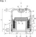
- FIG. 1 is a vertical cross-sectional view of an accumulator 1 according to some embodiments of the present invention.
- the accumulator 1 includes a substantially cylindrical pressure vessel 10 having at least one closed end and a partition portion separating the interior space of the pressure vessel 10 into a liquid chamber 16 (oil chamber) and a gas chamber 18.
- the accumulator 1 may include a bellows mechanism 40 accommodated in the pressure vessel 10 as the partition portion.
- Such an accumulator 1 is connectable to, for instance, a hydraulic oil circuit for brake or clutch in a vehicle and allows hydraulic oil (working fluid) to flow out of or into the hydraulic oil circuit. That is, the accumulator 1 functions as a buffer device which absorbs or accumulates pressure fluctuation (e.g., pulsation) in hydraulic oil in the hydraulic oil circuit.
- the accumulator 1 may be a so-called outside gas type accumulator 1 in which the liquid chamber 16 is located inside the bellows mechanism 40 (partition portion) while the gas chamber 18 (i.e., gas storage portion) is located outside the bellows mechanism 40 (see FIG. 1 , for instance).
- the pressure vessel 10 includes a first section 20 and a second section 30 joined to each other along a weld line 14 as a joint portion.
- the first section 20 includes an external cylinder portion 21 formed by a substantially cylindrical steel material (steel pipe) and a bottom plate portion 22 having a substantially circular plate shape and closing one end of the external cylinder portion 21 in the direction of the central axis A.
- the bottom plate portion 22 is connected to an end of the external cylinder portion 21 opposite to the second section 30 and extends in a plane perpendicular to the axial direction (central axis A).
- the first section 20 may be formed as an integral structure in which the external cylinder portion 21 and the bottom plate portion 22 are continuously formed by a single member. That is, the first section 20 may be formed such that the external cylinder portion 21 and the bottom plate portion 22 are continuous by processing such as pressing or forging, for instance. In some embodiments, the first section 20 may be formed such that the external cylinder portion 21 and the bottom plate portion 22 are continuous along a smooth curve. With this configuration, it is possible to form the pressure vessel 10 in a shape which is unlikely to cause cracks and corrosion due to stress concentration, for instance.
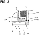
- a thread portion 28 whose axis is parallel to the central axis A is formed on an outer peripheral surface of the other end (on a side adjacent to the second section 30) of the external cylinder portion 21 (see FIG. 2 , for instance). That is, the external cylinder portion 21 extends along the axial direction of the thread portion 28.
- the first section 20 includes the thread portion 28 for fastening the accumulator 1 to a support member 50.
- the thread portion 28 is formed on the outer peripheral surface of the external cylinder portion 21 of the first section 20, it is unnecessary to form a threaded port for fastening the accumulator 1 to the support member 50 on the second section 30, and it is possible to simplify the structure of the second section 30.
- the thread portion 28 will be described later.
- the bottom plate portion 22 of the first section 20 is provided with a tool engagement portion 23 capable of engaging with a tool for rotating the accumulator 1 about the central axis A, a through hole 24 for introducing a gas from the outside of the accumulator 1 into the gas chamber 18 inside the accumulator 1, and a gas sealing stopper 25 for sealing the through hole 24 after the gas is charged into the gas chamber 18.
- the tool engagement portion 23 may be formed so as to be recessed (concave) inward along the central axis A and centered on the central axis A in the bottom plate portion 22 (see FIG. 1 , for instance).
- a concave tool engagement portion 23 only needs to be able to engage with a tool for imparting a rotational force about the central axis A to the accumulator 1, and may be a recess having a variety of shapes, such as cross (+) or slot (-), polygon such as triangle, square, pentagon, hexagon, octagon, star, or Torx (registered trademark).
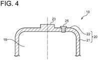
- the tool engagement portion 23 may be formed so as to protrude outward along the direction of the central axis A and centered on the central axis A in the bottom plate portion 22 of the first section 20 (see FIGs. 4 and 5 , for instance).
- Such a convex tool engagement portion 23 only needs to be able to engage with a tool for imparting a rotational force about the central axis A to the accumulator 1, and may have a variety of polygonal shapes, such as triangle, square, pentagon, hexagon, octagon or star.
- both the thread portion 28 and the tool engagement portion 23 are formed in the first section 20 as an integral structure, it is possible to easily improve the coaxial accuracy between the thread portion 28 and the tool engagement portion 23.
- the through hole 24 and the gas sealing stopper 25 may be offset and displaced from the central axis A and the tool engagement portion 23 in the radial direction (see FIGs. 1 and 4 , for instance), or may be placed along the central axis A (see FIG. 5 , for instance).
- the gas sealing stopper 25 is attached to the bottom plate portion 22 by welding such as resistance welding to seal the through hole 24 after the gas is charged into the gas chamber 18.
- the second section 30 includes a bottomed cylindrical internal cylinder portion 31 concentric with the external cylinder portion 21 inside the external cylinder portion 21 of the first section 20, and a flange portion 32 extending from one end of the internal cylinder portion 31 toward the outer periphery (outward in the radial direction of the internal cylinder portion 31).
- the internal cylinder portion 31 is formed on the inner peripheral side of a bellows 41, described later, so as to protrude toward the liquid chamber 16.
- a bottom 31A of the internal cylinder portion 31 may be a substantially circular flat plate extending perpendicular to the central axis A.
- At least one through hole 35 connecting a hydraulic oil circuit (hydraulic circuit) and the liquid chamber 16 is formed at the center of the bottom 31A of the internal cylinder portion 31 (see FIG. 1 , for instance).
- the flange portion 32 is connected to an end of the internal cylinder portion 31 adjacent to the support member 50 so as to extend outward in the radial direction of the internal cylinder portion 31 from the end of the internal cylinder portion 31.
- the internal cylinder portion 31 and the flange portion 32 are continuously formed by a single member as an integral structure. That is, the second section 30 may be formed such that the internal cylinder portion 31 and the flange portion 32 are continuous and have a convex or hat-like cross-section, for instance, by processing such as pressing or forging.
- the internal cylinder portion 31 for achieving the self-seal structure with the bellows mechanism 40 (partition portion) including the bellows 41 is formed integrally with the flange portion 32, the number of components and thus the cost are expected to be reduced, compared with the case where the internal cylinder portion 31 and the flange portion 32 separately formed are joined by welding or the like.
- the reduction in the number of components reduces welding portions or reduces or eliminates welding process between the internal cylinder portion 31 and the flange portion 32, thus simplifying the manufacturing procedure of the accumulator 1. Consequently, in addition to the reduction in cost, the quality of products can be easily controlled.
- the flange portion 32 is connected at the outermost edge to the other end of the external cylinder portion 21. That is, the outer diameter of the flange portion 32 is substantially the same as the outer diameter of the external cylinder portion 21.
- the flange portion 32 has an inner surface 32A facing toward the liquid chamber 16 which is inside the pressure vessel 10 and an outer surface 32B facing toward the support member 50 which is outside the pressure vessel 10.
- a fixation portion 41A (see FIG. 2 , for instance) disposed at one end of the bellows 41 is fixed to the inner surface 32A by welding.
- the welding may be electron beam welding or laser beam welding, for instance.
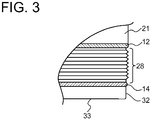
- the outer surface 32B of the flange portion 32 has an abutting portion 33 to abut on the support member 50. That is, the second section 30 includes the abutting portion 33 configured to abut on the support member 50 when the accumulator 1 is fastened to the support member 50.
- the abutting portion 33 is disposed opposite to the thread portion 28 across the weld line 14 in the axial direction of the thread portion 28 (see FIGs. 1 and 2 , for instance).
- the abutting portion 33 may be an annular projection formed by an outer peripheral portion of the flange portion 32 protruding toward the support member 50 at a predetermined thickness. In some embodiments, the abutting portion 33 is formed with a predetermined width (thickness) so as to come into surface contact with the support member 50. In another embodiments, the abutting portion 33 may be formed with a relatively thin thickness so as to come into line contact with the support member 50. The thickness, shape and position of the abutting portion 33 may be appropriately designed so that hydraulic oil in the hydraulic oil circuit is appropriately sealed by the abutting portion 33, the thread portion 28 and an O-ring 12 or the like when the accumulator 1 is attached to the support member 50 by the thread portion 28.
- the bellows mechanism 40 functions as the partition portion which separates the interior space of the pressure vessel 10 into the liquid chamber 16 and the gas chamber 18 so that a volume ratio between the liquid chamber 16 and the gas chamber 18 in the pressure vessel 10 is variable.
- the bellows mechanism 40 includes a bellows 41 (metal bellows) configured to expand and contract along the axial direction (central axis A) of the thread portion 28, a disc-like bellows cap 42 connected to the other end of the bellows 41, a bellows guide 43 disposed on the outer periphery of the bellows cap 42, and a seal 44 disposed on the liquid chamber 16 side of the bellows cap 42.
- the bellows guide 43 guides and moves the bellows 41, the bellows cap 42, and the seal 44 along the direction of the central axis A in accordance with the change in volume ratio between the liquid chamber 16 and the gas chamber 18 due to inflow and outflow of hydraulic oil between the hydraulic oil circuit and the liquid chamber 16.
- the bellows guide 43 abuts on the inner peripheral surface of the external cylinder portion 21 so as to ensure liquid-tight and gas- tight properties between the liquid chamber 16 and the gas chamber 18.
- the bellows guide 43 is configured to slidably move on and along the inner peripheral surface of the external cylinder portion 21 (in the direction of the central axis A) in response to the change in volume ratio between the liquid chamber 16 and the gas chamber 18.
- FIG. 1 shows a state where the bellows mechanism 40 contracts and the volume ratio of the liquid chamber 16 is minimized.
- the seal 44 (stay self seal) liquid-tightly seals the liquid chamber 16 when the bellows 41 maximally contracts, i.e., when the volume ratio of the liquid chamber 16 is minimized while the volume ratio of the gas chamber 18 is maximized (see FIG. 1 , for instance).
- the thread portion 28 (male thread) is formed on the outer periphery of the other end of the external cylinder portion 21.
- the thread portion 28 is screwing the thread portion 28 with a thread portion (female thread) formed in the support member 50, the accumulator 1 is connected to the hydraulic oil circuit.
- the thread portion 28 may extend to a position adjoining the weld line 14. In other embodiments, the thread portion 28 may be formed so as not to reach the weld line 14. In other words, in some embodiments, a thread-free portion may be formed between the thread portion 28 and the weld line 14.
- radial positions of the thread portion 28 and the weld line 14 may overlap. In some embodiments, when viewed from the direction of the central axis A, radial positions of the abutting portion 33 and the weld line 14 may overlap. Further, in some embodiments, when viewed from the direction of the central axis A, radial positions of the thread portion 28, the weld line 14, and the abutting portion 33 may overlap.
- the groove direction of the weld line 14 may extend in a direction perpendicular to the axial direction of the thread portion 28 (i.e., in the radial direction). More specifically, the other end (end adjacent to the support member 50) of the external cylinder portion 21 of the first section 20 may face an outermost edge of the inner peripheral surface 32A of the flange portion 32 of the second section 30. As a result, compressive force due to axial force of the thread portion 28 effectively acts on the weld line 14 from the perpendicular direction (straight ahead).
- an O-ring 12 for sealing is disposed on the outer periphery of the external cylinder portion 21 on a side opposite to the support member 50 across the thread portion 28.
- the external cylinder portion 21 may include an engagement groove for receiving the O-ring 12 along the outer periphery thereof.
- the engagement groove may be formed along and adjacent to the thread portion 28 on a side opposite to the support member 50 across the thread portion 28.
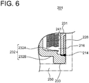
- a thread portion 228 (female thread) may be formed on the outer peripheral side of the internal cylinder portion 231. More specifically, by screwing the thread portion 228 formed as a female thread with a male thread formed in the support member 250, the accumulator 201 may be connected to the hydraulic oil circuit.
- the internal cylinder portion 231 functions as the first section including the thread portion 228 for fastening the accumulator 201 to the support member.
- FIG. 6 shows an example of outside gas type in which the liquid chamber 216 is formed between the bellows 241 and the internal cylinder portion 231.
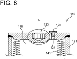
- FIG. 7 is a vertical cross-sectional view of an accumulator 101 according to some embodiments of the present invention.
- the accumulator 101 includes a substantially cylindrical pressure vessel 110 having at least one closed end and a partition portion separating the interior space of the pressure vessel 110 into a liquid chamber 116 (oil chamber) and a gas chamber 118.
- the accumulator 101 may include a bellows mechanism 140 accommodated in the pressure vessel 110 as the partition portion.
- Such an accumulator 101 is connectable to, for instance, a hydraulic oil circuit for brake or clutch in a vehicle and allows hydraulic oil (working fluid) to flow out of or into the hydraulic oil circuit. That is, the accumulator 101 functions as a buffer device which absorbs or accumulates pressure fluctuation (e.g., pulsation) in hydraulic oil in the hydraulic oil circuit.
- the accumulator 101 may be a so-called inside gas type accumulator 101 in which a liquid chamber 116 is located outside a bellows mechanism 140 (partition portion) while a gas chamber 118 (gas storage portion) is located inside the bellows mechanism 140 (see FIG. 7 , for instance).
- a pressure vessel 110 includes a first section 120 and a second section 130 joined to each other along a weld line 114.
- the first section 120 includes an external cylinder portion 121 formed by a substantially cylindrical steel material (steel pipe) and a bottom plate portion 122 having a substantially circular plate shape and closing one end of the external cylinder portion 121 in the direction of the central axis A.
- the bottom plate portion 122 is connected to an end of the external cylinder portion 121 opposite to the second section 130 and extends in a plane perpendicular to the axial direction (central axis A).
- the external cylinder portion 121 and the bottom plate portion 122 are connected by welding. More specifically, one end portion of the external cylinder portion 121 along the central axis A is welded and fixed to a facing outer peripheral edge portion of the bottom plate portion 122 on the inner surface of the pressure vessel 110.
- a fixation portion 141A (see FIG. 7 , for instance) disposed at one end of the bellows 141 is fixed to the inner surface of the bottom plate portion 122 by welding.
- the welding may be electron beam welding or laser beam welding, for instance.
- a thread portion 128 whose axis is parallel to the central axis A is formed on an outer peripheral surface of the other end (on a side adjacent to the second section 130) of the external cylinder portion 121. That is, the external cylinder portion 121 extends along the axial direction of the thread portion 128.
- the first section 120 includes the thread portion 128 for fastening the accumulator 1 to a support member 50.
- the bottom plate portion 122 of the first section 120 is provided with a tool engagement portion 123 capable of engaging with a tool for rotating the accumulator 101 about the central axis A, a through hole 124 for introducing a gas from the outside of the accumulator 101 into the gas chamber 118 inside the accumulator 101, and a gas sealing stopper 125 for sealing the through hole 124 after the gas is charged into the gas chamber 118.
- the tool engagement portion 123 may be formed so as to protrude outward along the direction of the central axis A and centered on the central axis A in the bottom plate portion 122 of the first section 120 (see FIG. 7 , for instance).
- Such a convex tool engagement portion 123 only needs to be able to engage with a tool for imparting a rotational force about the central axis A to the accumulator 101, and may have a variety of polygonal shapes, such as triangle, square, pentagon, hexagon, octagon or star.
- the tool engagement portion 123 may be formed so as to be recessed (concave) inward along the direction of the central axis A and centered on the central axis A in the bottom plate portion 122 (see FIG. 8 , for instance).
- a concave tool engagement portion 123 only needs to be able to engage with a tool for imparting a rotational force about the central axis A to the accumulator 101, and may be a recess having a variety of shapes, such as cross (+) or slot (-), polygon such as triangle, square, pentagon, hexagon, octagon, star, or Torx (registered trademark).
- both the thread portion 128 and the tool engagement portion 123 are formed in the first section 120, it is possible to easily improve the coaxial accuracy between the thread portion 128 and the tool engagement portion 123.
- the through hole 124 and the gas sealing stopper 125 may be offset and displaced from the central axis A and the tool engagement portion 123 in the radial direction (see FIG. 8 , for instance), or may be placed along the central axis A (see FIG. 7 , for instance).
- the gas sealing stopper 125 is attached to the bottom plate portion 122 by welding such as resistance welding to seal the through hole 124 after the gas is charged into the gas chamber 118.
- the second section 130 includes a bottomed cylindrical internal cylinder portion 131 concentric with the external cylinder portion 120 inside the external cylinder portion 21 of the first section 120, and a flange portion 132 extending from one end of the internal cylinder portion 131 toward the outer periphery (outward in the radial direction of the internal cylinder portion 131).
- the internal cylinder portion 131 is formed outside a bellows 141, described later, so as to protrude toward the liquid chamber 116.
- a surface of the internal cylinder portion 131 facing the liquid chamber 116 may be a substantially annular flat surface extending perpendicular to the central axis A.
- At least one through hole 135 connecting a hydraulic oil circuit (hydraulic circuit) and the liquid chamber 116 is formed at the center of the internal cylinder portion 131 (see FIG. 7 , for instance).
- the flange portion 132 is connected to an end of the internal cylinder portion 131 adjacent to the support member 50 so as to extend outward in the radial direction of the internal cylinder portion 131 from the end of the internal cylinder portion 131.
- the internal cylinder portion 131 and the flange portion 132 are continuously formed by a single member as an integral structure. That is, the second section 130 may be formed such that the internal cylinder portion 131 and the flange portion 132 are continuous and have a convex or hat-like cross-section, for instance, by processing such as pressing or forging.
- the internal cylinder portion 131 for achieving the self-seal structure with the bellows mechanism 140 (partition portion) including the bellows 141 is formed integrally with the flange portion 132, the number of components and thus the cost are expected to be reduced, compared with the case where the internal cylinder portion 131 and the flange portion 132 separately formed are joined by welding or the like.
- the reduction in the number of components reduces welding portions or reduces or eliminates welding process between the internal cylinder portion 131 and the flange portion 132, thus simplifying the manufacturing procedure of the accumulator 101. Consequently, in addition to the reduction in cost, the quality of products can be easily controlled.
- the flange portion 132 is connected at the outermost edge to the other end of the external cylinder portion 121. That is, the outer diameter of the flange portion 132 is substantially the same as the outer diameter of the external cylinder portion 121.
- the flange portion 132 has an inner surface 132A facing toward the liquid chamber 116 which is inside the pressure vessel 110 and an outer surface 132B facing toward the support member 50 which is outside the pressure vessel 110.
- the outer surface 132B of the flange portion 132 has an abutting portion 133 to abut on the support member 50. That is, the second section 130 includes the abutting portion 133 configured to abut on the support member 50 when the accumulator 101 is fastened to the support member 50.
- the abutting portion 133 is disposed opposite to the thread portion 128 across the weld line 114 in the axial direction of the thread portion 128 (see FIG. 7 , for instance).
- the abutting portion 133 may be an annular projection formed by an outer peripheral portion of the flange portion 132 protruding toward the support member 50 at a predetermined thickness. In some embodiments, the abutting portion 133 is formed with a predetermined width (thickness) so as to come into surface contact with the support member 50. In another embodiments, the abutting portion 133 may be formed with a relatively thin thickness so as to come into line contact with the support member 50.
- the thickness, shape and position of the abutting portion 133 may be appropriately designed so that hydraulic oil in the hydraulic oil circuit is appropriately sealed by the abutting portion 133, the thread portion 128 and the O-ring 112 or the like when the accumulator 101 is attached to the support member 50 by the thread portion 128.
- the bellows mechanism 140 functions as the partition portion which separates the interior space of the pressure vessel 110 into the liquid chamber 116 and the gas chamber 118 so that a volume ratio between the liquid chamber 116 and the gas chamber 118 in the pressure vessel 110 is variable.
- the bellows mechanism 140 includes a bellows 141 (metal bellows) configured to expand and contract along the axial direction (central axis A) of the thread portion 128, a disc-like bellows cap 142 connected to the other end of the bellows 141, a bellows guide 143 disposed on the outer periphery of the bellows cap 142, and a seal 144 disposed on the liquid chamber 116 side of the bellows cap 142.
- the bellows guide 143 guides and moves the bellows 141, the bellows cap 142, and the seal 144 along the direction of the central axis A in accordance with the change in volume ratio between the liquid chamber 116 and the gas chamber 118 in response to inflow and outflow of hydraulic oil between the hydraulic oil circuit and the liquid chamber 116.
- the bellows guide 143 abuts on the inner peripheral surface of the external cylinder portion 121 so as to ensure liquid-tight and gas-tight properties between the liquid chamber 116 and the gas chamber 118.
- the bellows guide 143 is configured to slidably move on and along the inner peripheral surface of the external cylinder portion 121 (in the direction of the central axis A) in response to the change in volume ratio between the liquid chamber 116 and the gas chamber 118.
- FIG. 7 shows a state where the bellows mechanism 140 expands and the volume ratio of the liquid chamber 116 is minimized.
- the seal 144 (stay self seal) liquid-tightly seals the liquid chamber 116 when the bellows 141 maximally expands, i.e., when the volume ratio of the liquid chamber 116 is minimized while the volume ratio of the gas chamber 118 is maximized (see FIG. 7 , for instance).
- the thread portion 128 may extend to a position adjoining the weld line 114. In other embodiments, the thread portion 128 may be formed so as not to reach the weld line 114. In other words, in some embodiments, a thread-free portion may be formed between the thread portion 128 and the weld line 114.
- radial positions of the thread portion 128 and the weld line 114 may overlap. In some embodiments, when viewed from the direction of the central axis A, radial positions of the abutting portion 133 and the weld line 114 may overlap. Further, in some embodiments, when viewed from the direction of the central axis A, radial positions of the thread portion 128, the weld line 114, and the abutting portion 133 may overlap.
- the groove direction of the weld line 114 may extend in a direction perpendicular to the axial direction of the thread portion 128 (i.e., in the radial direction). More specifically, the other end (end adjacent to the support member 50) of the external cylinder portion 121 of the first section 120 may face an outermost edge of the inner peripheral surface 132A of the flange portion 132 of the second section 130. As a result, compressive force due to axial force of the thread portion 128 effectively acts on the weld line 114 from the perpendicular direction (straight ahead).
- an O-ring 112 for sealing is disposed on the outer periphery of the external cylinder portion 121 on a side opposite to the support member 50 across the thread portion 128.
- the external cylinder portion 121 may include an engagement groove for receiving the O-ring 112 along the outer periphery thereof.
- the engagement groove may be formed along and adjacent to the thread portion 128 on a side opposite to the support member 50 across the thread portion 128.
- the weld line 114 between the first section 120 and the second section 130 of the pressure vessel 110 is positioned between the thread portion 128 of the first section 120 and the abutting portion 133 of the second section 130. Accordingly, compressive force due to axial force caused at the thread portion 128 effectively acts on the weld line 114 when the accumulator 101 is fastened to the support member 50. Thus, it is possible to at least partially cancel tension acting on the weld line 114 due to pressure difference between inside and outside of the pressure vessel 120, and it is possible to reduce damage risk in the vicinity of the weld line 114 of the pressure vessel 110.
Landscapes
- Engineering & Computer Science (AREA)
- General Engineering & Computer Science (AREA)
- Mechanical Engineering (AREA)
- Physics & Mathematics (AREA)
- Fluid Mechanics (AREA)
- Supply Devices, Intensifiers, Converters, And Telemotors (AREA)
Applications Claiming Priority (2)
| Application Number | Priority Date | Filing Date | Title |
|---|---|---|---|
| JP2017047751A JP6702905B2 (ja) | 2017-03-13 | 2017-03-13 | アキュムレータ |
| PCT/JP2018/002307 WO2018168216A1 (ja) | 2017-03-13 | 2018-01-25 | アキュムレータ |
Publications (3)
| Publication Number | Publication Date |
|---|---|
| EP3597931A1 EP3597931A1 (en) | 2020-01-22 |
| EP3597931A4 EP3597931A4 (en) | 2020-02-26 |
| EP3597931B1 true EP3597931B1 (en) | 2021-08-04 |
Family
ID=63522989
Family Applications (1)
| Application Number | Title | Priority Date | Filing Date |
|---|---|---|---|
| EP18768011.1A Active EP3597931B1 (en) | 2017-03-13 | 2018-01-25 | Accumulator |
Country Status (7)
Families Citing this family (1)
| Publication number | Priority date | Publication date | Assignee | Title |
|---|---|---|---|---|
| CN118564515B (zh) * | 2024-08-05 | 2024-10-22 | 中南大学 | 一种相变式连续气体发生装置及控制方法 |
Family Cites Families (33)
| Publication number | Priority date | Publication date | Assignee | Title |
|---|---|---|---|---|
| US2267121A (en) * | 1939-09-06 | 1941-12-23 | George H Mcmullen | Gas injector for liquid systems |
| US2385016A (en) * | 1943-06-21 | 1945-09-18 | Mercier Jean | Locking valve |
| GB713940A (en) * | 1951-08-31 | 1954-08-18 | British Messier Ltd | Improvements in or relating to hydraulic accumulators and the like |
| US2774619A (en) * | 1953-07-04 | 1956-12-18 | Mercier Jean | Sealing means for a slidable member in a pressure unit |
| US2829672A (en) | 1955-03-23 | 1958-04-08 | Superior Pipe Specialties Co | Accumulator |
| US3136340A (en) * | 1960-06-17 | 1964-06-09 | Mc Graw Edison Co | Accumulator for hydraulic systems |
| US3162213A (en) * | 1962-06-13 | 1964-12-22 | Melville F Peters | Surge attenuating devices |
| US3198213A (en) * | 1962-12-21 | 1965-08-03 | Gen Precision Inc | Unit area ratio accumulator with fail-safe means |
| FR1422967A (fr) * | 1964-11-16 | 1966-01-03 | Olaer Patent Co | Perfectionnements aux moyens d'accrochage de corps souples ou élastiques pour capacités destinées à être mises sous pression |
| DE1751917A1 (de) | 1968-08-17 | 1971-08-19 | Langen & Co | Hydro-pneumatischer Druckspeicher |
| ES499284A0 (es) | 1980-02-27 | 1982-01-01 | Leduc Rene Hydro Sa | Procedimiento de fabricacion de acumuladores hidraulicos |
| JPH0246301A (ja) * | 1988-08-04 | 1990-02-15 | Eagle Ind Co Ltd | アキュムレータ |
| ATE117407T1 (de) | 1991-04-16 | 1995-02-15 | Siemens Ag | Verfahren und vorrichtung zur überwachung des betriebszustandes einer dampfturbine. |
| US5219000A (en) * | 1992-05-29 | 1993-06-15 | General Motors Corporation | Fluid pressure accumulator |
| DE60119792T2 (de) * | 2000-05-30 | 2007-05-10 | NHK Spring Co., Ltd., Yokohama | Druckspeicher |
| JP2003074503A (ja) | 2001-09-04 | 2003-03-12 | Nok Corp | アキュムレータ |
| EP1498615B1 (en) * | 2002-04-19 | 2008-05-14 | Advics Co., Ltd. | Hydraulic accumulator |
| JP4272604B2 (ja) | 2004-08-23 | 2009-06-03 | 日本発條株式会社 | 圧力容器及び蓄圧・緩衝装置 |
| JP5102576B2 (ja) | 2007-10-10 | 2012-12-19 | Nok株式会社 | アキュムレータ |
| JP5201722B2 (ja) | 2008-03-26 | 2013-06-05 | イーグル工業株式会社 | 金属ベローズ式アキュムレータ |
| JP5474333B2 (ja) | 2008-11-05 | 2014-04-16 | イーグル工業株式会社 | アキュムレータ |
| JP3148349U (ja) | 2008-11-26 | 2009-02-12 | 日本発條株式会社 | アキュムレータ |
| US8277205B2 (en) * | 2009-03-06 | 2012-10-02 | GM Global Technology Operations LLC | Active electric accumulator |
| DE102010024126A1 (de) * | 2010-06-17 | 2011-12-22 | Carl Freudenberg Kg | Kolbenspeicher |
| CN101936312A (zh) * | 2010-09-15 | 2011-01-05 | 上海汇益控制系统股份有限公司 | 高压活塞式蓄能器 |
| JP5637394B2 (ja) | 2011-05-13 | 2014-12-10 | イーグル工業株式会社 | 金属ベローズ式アキュムレータ |
| ITBO20120233A1 (it) * | 2012-04-27 | 2013-10-28 | Magneti Marelli Spa | Servocomando idraulico di un cambio servocomandato |
| CN105508317A (zh) * | 2014-10-11 | 2016-04-20 | 天津海莱姆科技有限公司 | 非金属缠绕活塞式蓄能器 |
| CN204213070U (zh) * | 2014-10-11 | 2015-03-18 | 天津海莱姆科技有限公司 | 复合结构焊接蓄能器 |
| CN104405697A (zh) * | 2014-11-26 | 2015-03-11 | 常州飞宇化工有限公司 | 一种螺纹连接式胶囊蓄能器 |
| WO2016208478A1 (ja) * | 2015-06-22 | 2016-12-29 | イーグル工業株式会社 | アキュムレータ |
| JP6355601B2 (ja) * | 2015-08-21 | 2018-07-11 | 株式会社アドヴィックス | アキュムレータ |
| EP3623642B1 (en) * | 2017-05-11 | 2024-01-10 | Eagle Industry Co., Ltd. | Accumulator |
-
2017
- 2017-03-13 JP JP2017047751A patent/JP6702905B2/ja active Active
-
2018
- 2018-01-25 KR KR1020197025532A patent/KR102185030B1/ko active Active
- 2018-01-25 CA CA3056334A patent/CA3056334C/en active Active
- 2018-01-25 EP EP18768011.1A patent/EP3597931B1/en active Active
- 2018-01-25 CN CN201880017239.6A patent/CN110418900B/zh active Active
- 2018-01-25 WO PCT/JP2018/002307 patent/WO2018168216A1/ja unknown
- 2018-01-25 US US16/492,719 patent/US11255351B2/en active Active
Also Published As
| Publication number | Publication date |
|---|---|
| CA3056334A1 (en) | 2018-09-20 |
| KR20190109761A (ko) | 2019-09-26 |
| JP2018151003A (ja) | 2018-09-27 |
| JP6702905B2 (ja) | 2020-06-03 |
| EP3597931A4 (en) | 2020-02-26 |
| CN110418900B (zh) | 2021-02-12 |
| WO2018168216A1 (ja) | 2018-09-20 |
| US20200032819A1 (en) | 2020-01-30 |
| CN110418900A (zh) | 2019-11-05 |
| EP3597931A1 (en) | 2020-01-22 |
| CA3056334C (en) | 2021-05-11 |
| KR102185030B1 (ko) | 2020-12-01 |
| US11255351B2 (en) | 2022-02-22 |
Similar Documents
| Publication | Publication Date | Title |
|---|---|---|
| US7318452B2 (en) | Accumulator | |
| US8746286B2 (en) | Hydraulic accumulator | |
| US10421662B2 (en) | Sensor fixing structure including valve body and pressure sensor | |
| EP3597932B1 (en) | Accumulator | |
| WO2016208478A1 (ja) | アキュムレータ | |
| EP3597931B1 (en) | Accumulator | |
| US20170261061A1 (en) | Shock absorber | |
| US12331760B2 (en) | Hydraulic accumulator | |
| US20210317892A1 (en) | Shock absorber | |
| US10520084B2 (en) | Metal bellows | |
| EP4067715A1 (en) | Power element and expansion valve using same | |
| US12061025B2 (en) | Power element and expansion valve using same | |
| US10118244B2 (en) | Weld structure for refrigerant circuit component and welding method for refrigerant circuit component | |
| KR20180102507A (ko) | 고성능 어큐뮬레이터 | |
| US20210199629A1 (en) | Chromatography cartridge seal arrangement | |
| US10794447B2 (en) | Bump stopper and shock absorber | |
| EP3029337B1 (en) | Accumulator | |
| JP2014095558A (ja) | 接続パーツおよび差圧/圧力発信器 | |
| JP2000170703A (ja) | アキュムレ―タ |
Legal Events
| Date | Code | Title | Description |
|---|---|---|---|
| STAA | Information on the status of an ep patent application or granted ep patent |
Free format text: STATUS: THE INTERNATIONAL PUBLICATION HAS BEEN MADE |
|
| PUAI | Public reference made under article 153(3) epc to a published international application that has entered the european phase |
Free format text: ORIGINAL CODE: 0009012 |
|
| STAA | Information on the status of an ep patent application or granted ep patent |
Free format text: STATUS: REQUEST FOR EXAMINATION WAS MADE |
|
| 17P | Request for examination filed |
Effective date: 20190912 |
|
| AK | Designated contracting states |
Kind code of ref document: A1 Designated state(s): AL AT BE BG CH CY CZ DE DK EE ES FI FR GB GR HR HU IE IS IT LI LT LU LV MC MK MT NL NO PL PT RO RS SE SI SK SM TR |
|
| AX | Request for extension of the european patent |
Extension state: BA ME |
|
| A4 | Supplementary search report drawn up and despatched |
Effective date: 20200129 |
|
| RIC1 | Information provided on ipc code assigned before grant |
Ipc: F15B 1/24 20060101ALI20200123BHEP Ipc: F15B 1/08 20060101AFI20200123BHEP Ipc: F15B 1/10 20060101ALI20200123BHEP |
|
| DAV | Request for validation of the european patent (deleted) | ||
| DAX | Request for extension of the european patent (deleted) | ||
| GRAP | Despatch of communication of intention to grant a patent |
Free format text: ORIGINAL CODE: EPIDOSNIGR1 |
|
| STAA | Information on the status of an ep patent application or granted ep patent |
Free format text: STATUS: GRANT OF PATENT IS INTENDED |
|
| INTG | Intention to grant announced |
Effective date: 20210413 |
|
| GRAS | Grant fee paid |
Free format text: ORIGINAL CODE: EPIDOSNIGR3 |
|
| GRAA | (expected) grant |
Free format text: ORIGINAL CODE: 0009210 |
|
| STAA | Information on the status of an ep patent application or granted ep patent |
Free format text: STATUS: THE PATENT HAS BEEN GRANTED |
|
| AK | Designated contracting states |
Kind code of ref document: B1 Designated state(s): AL AT BE BG CH CY CZ DE DK EE ES FI FR GB GR HR HU IE IS IT LI LT LU LV MC MK MT NL NO PL PT RO RS SE SI SK SM TR |
|
| REG | Reference to a national code |
Ref country code: GB Ref legal event code: FG4D |
|
| REG | Reference to a national code |
Ref country code: AT Ref legal event code: REF Ref document number: 1417251 Country of ref document: AT Kind code of ref document: T Effective date: 20210815 |
|
| REG | Reference to a national code |
Ref country code: CH Ref legal event code: EP |
|
| REG | Reference to a national code |
Ref country code: DE Ref legal event code: R096 Ref document number: 602018021313 Country of ref document: DE |
|
| REG | Reference to a national code |
Ref country code: IE Ref legal event code: FG4D |
|
| REG | Reference to a national code |
Ref country code: LT Ref legal event code: MG9D |
|
| REG | Reference to a national code |
Ref country code: NL Ref legal event code: MP Effective date: 20210804 |
|
| REG | Reference to a national code |
Ref country code: AT Ref legal event code: MK05 Ref document number: 1417251 Country of ref document: AT Kind code of ref document: T Effective date: 20210804 |
|
| PG25 | Lapsed in a contracting state [announced via postgrant information from national office to epo] |
Ref country code: HR Free format text: LAPSE BECAUSE OF FAILURE TO SUBMIT A TRANSLATION OF THE DESCRIPTION OR TO PAY THE FEE WITHIN THE PRESCRIBED TIME-LIMIT Effective date: 20210804 Ref country code: FI Free format text: LAPSE BECAUSE OF FAILURE TO SUBMIT A TRANSLATION OF THE DESCRIPTION OR TO PAY THE FEE WITHIN THE PRESCRIBED TIME-LIMIT Effective date: 20210804 Ref country code: ES Free format text: LAPSE BECAUSE OF FAILURE TO SUBMIT A TRANSLATION OF THE DESCRIPTION OR TO PAY THE FEE WITHIN THE PRESCRIBED TIME-LIMIT Effective date: 20210804 Ref country code: RS Free format text: LAPSE BECAUSE OF FAILURE TO SUBMIT A TRANSLATION OF THE DESCRIPTION OR TO PAY THE FEE WITHIN THE PRESCRIBED TIME-LIMIT Effective date: 20210804 Ref country code: SE Free format text: LAPSE BECAUSE OF FAILURE TO SUBMIT A TRANSLATION OF THE DESCRIPTION OR TO PAY THE FEE WITHIN THE PRESCRIBED TIME-LIMIT Effective date: 20210804 Ref country code: LT Free format text: LAPSE BECAUSE OF FAILURE TO SUBMIT A TRANSLATION OF THE DESCRIPTION OR TO PAY THE FEE WITHIN THE PRESCRIBED TIME-LIMIT Effective date: 20210804 Ref country code: AT Free format text: LAPSE BECAUSE OF FAILURE TO SUBMIT A TRANSLATION OF THE DESCRIPTION OR TO PAY THE FEE WITHIN THE PRESCRIBED TIME-LIMIT Effective date: 20210804 Ref country code: BG Free format text: LAPSE BECAUSE OF FAILURE TO SUBMIT A TRANSLATION OF THE DESCRIPTION OR TO PAY THE FEE WITHIN THE PRESCRIBED TIME-LIMIT Effective date: 20211104 Ref country code: PT Free format text: LAPSE BECAUSE OF FAILURE TO SUBMIT A TRANSLATION OF THE DESCRIPTION OR TO PAY THE FEE WITHIN THE PRESCRIBED TIME-LIMIT Effective date: 20211206 Ref country code: NO Free format text: LAPSE BECAUSE OF FAILURE TO SUBMIT A TRANSLATION OF THE DESCRIPTION OR TO PAY THE FEE WITHIN THE PRESCRIBED TIME-LIMIT Effective date: 20211104 |
|
| PG25 | Lapsed in a contracting state [announced via postgrant information from national office to epo] |
Ref country code: PL Free format text: LAPSE BECAUSE OF FAILURE TO SUBMIT A TRANSLATION OF THE DESCRIPTION OR TO PAY THE FEE WITHIN THE PRESCRIBED TIME-LIMIT Effective date: 20210804 Ref country code: LV Free format text: LAPSE BECAUSE OF FAILURE TO SUBMIT A TRANSLATION OF THE DESCRIPTION OR TO PAY THE FEE WITHIN THE PRESCRIBED TIME-LIMIT Effective date: 20210804 Ref country code: GR Free format text: LAPSE BECAUSE OF FAILURE TO SUBMIT A TRANSLATION OF THE DESCRIPTION OR TO PAY THE FEE WITHIN THE PRESCRIBED TIME-LIMIT Effective date: 20211105 |
|
| PG25 | Lapsed in a contracting state [announced via postgrant information from national office to epo] |
Ref country code: NL Free format text: LAPSE BECAUSE OF FAILURE TO SUBMIT A TRANSLATION OF THE DESCRIPTION OR TO PAY THE FEE WITHIN THE PRESCRIBED TIME-LIMIT Effective date: 20210804 |
|
| PG25 | Lapsed in a contracting state [announced via postgrant information from national office to epo] |
Ref country code: DK Free format text: LAPSE BECAUSE OF FAILURE TO SUBMIT A TRANSLATION OF THE DESCRIPTION OR TO PAY THE FEE WITHIN THE PRESCRIBED TIME-LIMIT Effective date: 20210804 |
|
| REG | Reference to a national code |
Ref country code: DE Ref legal event code: R097 Ref document number: 602018021313 Country of ref document: DE |
|
| PG25 | Lapsed in a contracting state [announced via postgrant information from national office to epo] |
Ref country code: SM Free format text: LAPSE BECAUSE OF FAILURE TO SUBMIT A TRANSLATION OF THE DESCRIPTION OR TO PAY THE FEE WITHIN THE PRESCRIBED TIME-LIMIT Effective date: 20210804 Ref country code: SK Free format text: LAPSE BECAUSE OF FAILURE TO SUBMIT A TRANSLATION OF THE DESCRIPTION OR TO PAY THE FEE WITHIN THE PRESCRIBED TIME-LIMIT Effective date: 20210804 Ref country code: RO Free format text: LAPSE BECAUSE OF FAILURE TO SUBMIT A TRANSLATION OF THE DESCRIPTION OR TO PAY THE FEE WITHIN THE PRESCRIBED TIME-LIMIT Effective date: 20210804 Ref country code: EE Free format text: LAPSE BECAUSE OF FAILURE TO SUBMIT A TRANSLATION OF THE DESCRIPTION OR TO PAY THE FEE WITHIN THE PRESCRIBED TIME-LIMIT Effective date: 20210804 Ref country code: CZ Free format text: LAPSE BECAUSE OF FAILURE TO SUBMIT A TRANSLATION OF THE DESCRIPTION OR TO PAY THE FEE WITHIN THE PRESCRIBED TIME-LIMIT Effective date: 20210804 Ref country code: AL Free format text: LAPSE BECAUSE OF FAILURE TO SUBMIT A TRANSLATION OF THE DESCRIPTION OR TO PAY THE FEE WITHIN THE PRESCRIBED TIME-LIMIT Effective date: 20210804 |
|
| PLBE | No opposition filed within time limit |
Free format text: ORIGINAL CODE: 0009261 |
|
| STAA | Information on the status of an ep patent application or granted ep patent |
Free format text: STATUS: NO OPPOSITION FILED WITHIN TIME LIMIT |
|
| 26N | No opposition filed |
Effective date: 20220506 |
|
| PG25 | Lapsed in a contracting state [announced via postgrant information from national office to epo] |
Ref country code: IT Free format text: LAPSE BECAUSE OF FAILURE TO SUBMIT A TRANSLATION OF THE DESCRIPTION OR TO PAY THE FEE WITHIN THE PRESCRIBED TIME-LIMIT Effective date: 20210804 |
|
| PG25 | Lapsed in a contracting state [announced via postgrant information from national office to epo] |
Ref country code: SI Free format text: LAPSE BECAUSE OF FAILURE TO SUBMIT A TRANSLATION OF THE DESCRIPTION OR TO PAY THE FEE WITHIN THE PRESCRIBED TIME-LIMIT Effective date: 20210804 Ref country code: MC Free format text: LAPSE BECAUSE OF FAILURE TO SUBMIT A TRANSLATION OF THE DESCRIPTION OR TO PAY THE FEE WITHIN THE PRESCRIBED TIME-LIMIT Effective date: 20210804 |
|
| REG | Reference to a national code |
Ref country code: CH Ref legal event code: PL |
|
| GBPC | Gb: european patent ceased through non-payment of renewal fee |
Effective date: 20220125 |
|
| REG | Reference to a national code |
Ref country code: BE Ref legal event code: MM Effective date: 20220131 |
|
| PG25 | Lapsed in a contracting state [announced via postgrant information from national office to epo] |
Ref country code: LU Free format text: LAPSE BECAUSE OF NON-PAYMENT OF DUE FEES Effective date: 20220125 Ref country code: GB Free format text: LAPSE BECAUSE OF NON-PAYMENT OF DUE FEES Effective date: 20220125 |
|
| PG25 | Lapsed in a contracting state [announced via postgrant information from national office to epo] |
Ref country code: BE Free format text: LAPSE BECAUSE OF NON-PAYMENT OF DUE FEES Effective date: 20220131 |
|
| PG25 | Lapsed in a contracting state [announced via postgrant information from national office to epo] |
Ref country code: LI Free format text: LAPSE BECAUSE OF NON-PAYMENT OF DUE FEES Effective date: 20220131 Ref country code: CH Free format text: LAPSE BECAUSE OF NON-PAYMENT OF DUE FEES Effective date: 20220131 |
|
| PG25 | Lapsed in a contracting state [announced via postgrant information from national office to epo] |
Ref country code: IE Free format text: LAPSE BECAUSE OF NON-PAYMENT OF DUE FEES Effective date: 20220125 |
|
| P01 | Opt-out of the competence of the unified patent court (upc) registered |
Effective date: 20230515 |
|
| PG25 | Lapsed in a contracting state [announced via postgrant information from national office to epo] |
Ref country code: MK Free format text: LAPSE BECAUSE OF FAILURE TO SUBMIT A TRANSLATION OF THE DESCRIPTION OR TO PAY THE FEE WITHIN THE PRESCRIBED TIME-LIMIT Effective date: 20210804 Ref country code: CY Free format text: LAPSE BECAUSE OF FAILURE TO SUBMIT A TRANSLATION OF THE DESCRIPTION OR TO PAY THE FEE WITHIN THE PRESCRIBED TIME-LIMIT Effective date: 20210804 |
|
| PG25 | Lapsed in a contracting state [announced via postgrant information from national office to epo] |
Ref country code: HU Free format text: LAPSE BECAUSE OF FAILURE TO SUBMIT A TRANSLATION OF THE DESCRIPTION OR TO PAY THE FEE WITHIN THE PRESCRIBED TIME-LIMIT; INVALID AB INITIO Effective date: 20180125 |
|
| PG25 | Lapsed in a contracting state [announced via postgrant information from national office to epo] |
Ref country code: TR Free format text: LAPSE BECAUSE OF FAILURE TO SUBMIT A TRANSLATION OF THE DESCRIPTION OR TO PAY THE FEE WITHIN THE PRESCRIBED TIME-LIMIT Effective date: 20210804 |
|
| PG25 | Lapsed in a contracting state [announced via postgrant information from national office to epo] |
Ref country code: MT Free format text: LAPSE BECAUSE OF FAILURE TO SUBMIT A TRANSLATION OF THE DESCRIPTION OR TO PAY THE FEE WITHIN THE PRESCRIBED TIME-LIMIT Effective date: 20210804 |
|
| PGFP | Annual fee paid to national office [announced via postgrant information from national office to epo] |
Ref country code: FR Payment date: 20241209 Year of fee payment: 8 |
|
| PGFP | Annual fee paid to national office [announced via postgrant information from national office to epo] |
Ref country code: DE Payment date: 20241203 Year of fee payment: 8 |