EP3597564B1 - Stand system for arranging panels - Google Patents
Stand system for arranging panels Download PDFInfo
- Publication number
- EP3597564B1 EP3597564B1 EP19171232.2A EP19171232A EP3597564B1 EP 3597564 B1 EP3597564 B1 EP 3597564B1 EP 19171232 A EP19171232 A EP 19171232A EP 3597564 B1 EP3597564 B1 EP 3597564B1
- Authority
- EP
- European Patent Office
- Prior art keywords
- coupling
- stands
- stand
- coupling part
- stand system
- Prior art date
- Legal status (The legal status is an assumption and is not a legal conclusion. Google has not performed a legal analysis and makes no representation as to the accuracy of the status listed.)
- Active
Links
Images


Classifications
-
- B—PERFORMING OPERATIONS; TRANSPORTING
- B65—CONVEYING; PACKING; STORING; HANDLING THIN OR FILAMENTARY MATERIAL
- B65G—TRANSPORT OR STORAGE DEVICES, e.g. CONVEYORS FOR LOADING OR TIPPING, SHOP CONVEYOR SYSTEMS OR PNEUMATIC TUBE CONVEYORS
- B65G1/00—Storing articles, individually or in orderly arrangement, in warehouses or magazines
- B65G1/02—Storage devices
- B65G1/14—Stack holders or separators
-
- B—PERFORMING OPERATIONS; TRANSPORTING
- B65—CONVEYING; PACKING; STORING; HANDLING THIN OR FILAMENTARY MATERIAL
- B65G—TRANSPORT OR STORAGE DEVICES, e.g. CONVEYORS FOR LOADING OR TIPPING, SHOP CONVEYOR SYSTEMS OR PNEUMATIC TUBE CONVEYORS
- B65G1/00—Storing articles, individually or in orderly arrangement, in warehouses or magazines
- B65G1/02—Storage devices
-
- B—PERFORMING OPERATIONS; TRANSPORTING
- B65—CONVEYING; PACKING; STORING; HANDLING THIN OR FILAMENTARY MATERIAL
- B65D—CONTAINERS FOR STORAGE OR TRANSPORT OF ARTICLES OR MATERIALS, e.g. BAGS, BARRELS, BOTTLES, BOXES, CANS, CARTONS, CRATES, DRUMS, JARS, TANKS, HOPPERS, FORWARDING CONTAINERS; ACCESSORIES, CLOSURES, OR FITTINGS THEREFOR; PACKAGING ELEMENTS; PACKAGES
- B65D19/00—Pallets or like platforms, with or without side walls, for supporting loads to be lifted or lowered
- B65D19/38—Details or accessories
- B65D19/44—Elements or devices for locating articles on platforms
-
- B—PERFORMING OPERATIONS; TRANSPORTING
- B65—CONVEYING; PACKING; STORING; HANDLING THIN OR FILAMENTARY MATERIAL
- B65D—CONTAINERS FOR STORAGE OR TRANSPORT OF ARTICLES OR MATERIALS, e.g. BAGS, BARRELS, BOTTLES, BOXES, CANS, CARTONS, CRATES, DRUMS, JARS, TANKS, HOPPERS, FORWARDING CONTAINERS; ACCESSORIES, CLOSURES, OR FITTINGS THEREFOR; PACKAGING ELEMENTS; PACKAGES
- B65D85/00—Containers, packaging elements or packages, specially adapted for particular articles or materials
- B65D85/30—Containers, packaging elements or packages, specially adapted for particular articles or materials for articles particularly sensitive to damage by shock or pressure
- B65D85/48—Containers, packaging elements or packages, specially adapted for particular articles or materials for articles particularly sensitive to damage by shock or pressure for glass sheets
-
- B—PERFORMING OPERATIONS; TRANSPORTING
- B65—CONVEYING; PACKING; STORING; HANDLING THIN OR FILAMENTARY MATERIAL
- B65G—TRANSPORT OR STORAGE DEVICES, e.g. CONVEYORS FOR LOADING OR TIPPING, SHOP CONVEYOR SYSTEMS OR PNEUMATIC TUBE CONVEYORS
- B65G49/00—Conveying systems characterised by their application for specified purposes not otherwise provided for
- B65G49/05—Conveying systems characterised by their application for specified purposes not otherwise provided for for fragile or damageable materials or articles
- B65G49/06—Conveying systems characterised by their application for specified purposes not otherwise provided for for fragile or damageable materials or articles for fragile sheets, e.g. glass
- B65G49/062—Easels, stands or shelves, e.g. castor-shelves, supporting means on vehicles
-
- A—HUMAN NECESSITIES
- A47—FURNITURE; DOMESTIC ARTICLES OR APPLIANCES; COFFEE MILLS; SPICE MILLS; SUCTION CLEANERS IN GENERAL
- A47F—SPECIAL FURNITURE, FITTINGS, OR ACCESSORIES FOR SHOPS, STOREHOUSES, BARS, RESTAURANTS OR THE LIKE; PAYING COUNTERS
- A47F7/00—Show stands, hangers, or shelves, adapted for particular articles or materials
- A47F7/0042—Show stands, hangers, or shelves, adapted for particular articles or materials for flat articles, e.g. panels, tiles
-
- B—PERFORMING OPERATIONS; TRANSPORTING
- B65—CONVEYING; PACKING; STORING; HANDLING THIN OR FILAMENTARY MATERIAL
- B65D—CONTAINERS FOR STORAGE OR TRANSPORT OF ARTICLES OR MATERIALS, e.g. BAGS, BARRELS, BOTTLES, BOXES, CANS, CARTONS, CRATES, DRUMS, JARS, TANKS, HOPPERS, FORWARDING CONTAINERS; ACCESSORIES, CLOSURES, OR FITTINGS THEREFOR; PACKAGING ELEMENTS; PACKAGES
- B65D2519/00—Pallets or like platforms, with or without side walls, for supporting loads to be lifted or lowered
- B65D2519/00004—Details relating to pallets
- B65D2519/00258—Overall construction
- B65D2519/00313—Overall construction of the base surface
- B65D2519/00328—Overall construction of the base surface shape of the contact surface of the base
- B65D2519/00333—Overall construction of the base surface shape of the contact surface of the base contact surface having a stringer-like shape
-
- B—PERFORMING OPERATIONS; TRANSPORTING
- B65—CONVEYING; PACKING; STORING; HANDLING THIN OR FILAMENTARY MATERIAL
- B65D—CONTAINERS FOR STORAGE OR TRANSPORT OF ARTICLES OR MATERIALS, e.g. BAGS, BARRELS, BOTTLES, BOXES, CANS, CARTONS, CRATES, DRUMS, JARS, TANKS, HOPPERS, FORWARDING CONTAINERS; ACCESSORIES, CLOSURES, OR FITTINGS THEREFOR; PACKAGING ELEMENTS; PACKAGES
- B65D2519/00—Pallets or like platforms, with or without side walls, for supporting loads to be lifted or lowered
- B65D2519/00004—Details relating to pallets
- B65D2519/00736—Details
- B65D2519/0081—Elements or devices for locating articles
- B65D2519/00815—Elements or devices for locating articles on the pallet
-
- B—PERFORMING OPERATIONS; TRANSPORTING
- B65—CONVEYING; PACKING; STORING; HANDLING THIN OR FILAMENTARY MATERIAL
- B65G—TRANSPORT OR STORAGE DEVICES, e.g. CONVEYORS FOR LOADING OR TIPPING, SHOP CONVEYOR SYSTEMS OR PNEUMATIC TUBE CONVEYORS
- B65G2201/00—Indexing codes relating to handling devices, e.g. conveyors, characterised by the type of product or load being conveyed or handled
- B65G2201/02—Articles
- B65G2201/0214—Articles of special size, shape or weigh
- B65G2201/022—Flat
-
- F—MECHANICAL ENGINEERING; LIGHTING; HEATING; WEAPONS; BLASTING
- F16—ENGINEERING ELEMENTS AND UNITS; GENERAL MEASURES FOR PRODUCING AND MAINTAINING EFFECTIVE FUNCTIONING OF MACHINES OR INSTALLATIONS; THERMAL INSULATION IN GENERAL
- F16M—FRAMES, CASINGS OR BEDS OF ENGINES, MACHINES OR APPARATUS, NOT SPECIFIC TO ENGINES, MACHINES OR APPARATUS PROVIDED FOR ELSEWHERE; STANDS; SUPPORTS
- F16M11/00—Stands or trestles as supports for apparatus or articles placed thereon ; Stands for scientific apparatus such as gravitational force meters
- F16M11/20—Undercarriages with or without wheels
- F16M11/22—Undercarriages with or without wheels with approximately constant height, e.g. with constant length of column or of legs
Definitions
- the invention relates to a stand system for arranging panels, and a stand for such a stand system.
- a sheeting support includes two identical end support assemblies, each having two base members pivotally coupled at first ends and two legs which are pivotally coupled to each other at their upper ends and which each have a lower end pivotally coupled to a respective base member.
- a connecting arrangement is provided to releasably couple the end support assemblies to each other.
- Each base member of each end support assembly has on an upper surface thereof a retaining strip which resists sliding movement therealong of an edge of a sheet disposed thereon, and also has at an outer end a retaining arrangement which includes a portion movable between an operational position projecting upwardly past an upper surface of the base member and a retracted position disposed below the upper surface of the base member.”
- US3698577 according to its introduction relates to "a system for transporting material. More particularly, this invention relates to a two-component system comprising a transporter and a container. Optionally, a third component, an upender, is included. The system is particularly useful for transporting materials in sheet form.”
- the present invention relates to a method for vertically arranging plasterboard panels for use at a workplace, comprising providing a plasterboard cart with at least one vertically arranged plasterboard panel, a bottom side of the plasterboard resting on a plasterboard support of the cart at a first level positioning at least one rack under the plasterboard panel provided on the cart, the rack having a plasterboard support at a second level, below the first level, mutually moving the plasterboard support of the cart and the plasterboard support of the rack such that the plasterboard support of the cart arrives at a lower level than the plasterboard support of the rack, so that the plasterboard panel is supported by the rack and removing the cart, leaving the plasterboard on the rack for use at a workplace.
- the invention further concerns a cart and a rack for use in the above method.”
- NL1040662 according to its abstract describes: "Buck for building plates, comprising a first and a second support, each of which is provided with foot parts in front supporting the supports on a surface, of first supporting surfaces for bottom edges of the plates and of second bearing surfaces for a main surface of a plate, and a connection for the connecting the first and second supports together, with the first and second supports and the connection be made of sheet material, the connection and the first and second supports being releasable are connected to each other, preferably without added fastener.”
- FR2809716 according to its abstract describes: "The wooden rack has two L-shaped uprights (10, 11) whose upper sections (12, 13) are trapezoidal and whose lower sections (14, 15) support a shelf (18). The back of this fits into slots in the uprights at the junction between the two sections. A cross-bar (20) fits into slots at the top of the uprights.”
- the later two provide a storage rack on or using a pallet, thus limiting its use.
- the current stand system is applicable for arranging panels.
- panels In particular, it allows panels to be arranged almost vertically.
- the long sides rest on the support surfaces of the stands, and the surface of one (upmost or lowest) panels rests against the back surfaces of the stands (in Dutch “bokken”).
- the invention further pertains to a pallet for holding at least two stacks of stacked stands of the stand system, in used supporting two stacks of stands stacked on their side surfaces and with a lower stand of each stack of stands resting with one side on a top pallet surface of said pallet, said pallet comprising engagement parts on said top pallet surface for engaging the lower stands, and positioned on said top pallet surface for engaging said two stacks 180 degrees rotated with respect to one another and preventing sliding of said lower stands off of said top surface.
- a stand system for arranging panels comprising at least two stands and at least one coupling element for coupling the at least two stands, said stands and said coupling element produced from plastic, said stands comprising:
- the first end and second end are in fact ends of the coupling element length.
- the coupling element has a width.
- the coupling element length can be for instance an elongated board with coupling parts at its opposite ends.
- the current stand system is suited for supporting panels. Often, such panels are gypsum board or plasterboard panels, but also other panels of sheets can be supported, like underlayment panels, but even glass and plastic sheet can be supported. Usually, these sheet or panels can rest on the stand system when supported. Usually, these panels have a length of roughly between 1 and 10 meters. For plasterboard, for instance, the length is between 1.5 and 4 meters. The panels or plates can have a width of roughly between 0.5 and 1.5 meters. Usually, a panel is between 1 and 25 kg. The stand system can hold up to 1000-1500 kg of panels per stand The stand system provides a stable stand system for supporting a stack of panels. After use, the stand system can be disassembled and can be stored or returned in a compact state. Furthermore, the stand system is relatively light weight.
- a current stand and coupling end is made from moldable of printable material.
- a plastic is selected.
- thermoplastic polymer material is selected, like for instance polyethylene (PE), polypropylene (PP), polyamide like nylon, Acrylonitrile butadiene-styrene (ABS).
- ABS Acrylonitrile butadiene-styrene
- bio-based or bio-degradable polymers can be used. These materials can either be re-used or recycled, or they can be for instance de composted.
- the stand system in fact provides an easel for a stack of panels.
- the stand system can also be seen as a system of stands that holds the stack of panels almost or substantially vertical, usually on a longitudinal side.
- the coupling part receiving part is adapted for allowing coupling of said first coupling part and said second coupling part.
- the coupling part receiving part is adapted for allowing said first coupling part and a second coupling part of another, similar coupling element to be coupled at the same time.
- two coupling elements can be coupled at the same stand, thus allowing providing a chain of coupled stands.
- first coupling part of one coupling element and said second coupling part of a similar coupling element are adapted for allowing simultaneous holding in a said coupling part receiving end of a stand.
- first and second coupling parts are designed such that when said coupling element and a further, similar coupling element are positioned in line said first coupling part of said coupling element and a said second coupling part of said further coupling element define one groove.
- the commonly resulting groove is substantially cross with respect to said coupling element length.
- the groove is a rectangular groove.
- the groove with groove walls engages the coupling part receiving part.
- end walls of said groove comprising flexible lips allowing insertion of said first and second coupling ends in said coupling part receiving part.
- the coupling part receiving part comprises a through hole for receiving said first coupling part and a said second coupling part of a further, similar coupling element.
- the through hole and said first and second coupling part mutually dimensioned that said coupling parts fill said through hole.
- said through hole is a slot hole.
- first and second coupling parts are flexible for snap-fitting in said coupling part receiving part.
- the stand system further comprises substantially parallel side planes for allowing stacking of said stands.
- one side plane has stacking parts cooperating with complementary stacking parts on the other side plane for preventing sliding of stands when stacked.
- a stand on one side comprises extensions extending from said side plane, and on its opposite side said stand comprises corresponding indents for receiving extensions from a further, similar stand.
- one side may comprise one or more extensions and one or more indents, and the opposite side comprises corresponding indents and extensions, respectively.
- the stand system further comprises a honeycomb structure having cells running between said side planes. This increases strength en reduces weight. It facilitated easy handling of the stands.
- the sole and said rear surface angled between 85 and 95 degrees. In an embodiment, the sole and rear surface are angled about 90 degrees. This facilitates rear surface coupling.
- the back surface and said support surface angled at between 90-130 degrees.
- An angle slightly larger than 90 degrees helps preventing panels from falling off the stands.
- the rear surface comprises rear coupling parts for coupling to a rear surface of a similar stand for providing backward coupled stands.
- the stands on their rear surfaces each comprises at least one first and second rear coupling parts for coupling to a rear surface of a similar stand for providing backward coupled stands, in particular said first and second rear coupling are provided functionally in line on a line on said rear surface in sideward direction, more in particular said first rear coupling part provided on one half of said rear surface and said second rear coupling part provided on an opposite half of said rear surface, said first and second rear coupling part complementary with respect to one another for allowing a said stand to coupling backward to a said similar stand, in particular coupling in a sideward sliding manner.
- two stands can be placed in their soles a little sidewards from one another but with their back surfaces in line.
- the first rear coupling part When shifting the stands in said plane towards each other, the first rear coupling part will engage the seconds rear coupling part and when shifting further the second rear coupling part will engage the first rear coupling part, and two stand will be securely coupled backwards. With simply shifting the stands.
- the first and second rear coupling parts will be provided with a complementary snap locking.
- the rear surface comprises at least two of said first and second rear coupling parts at a distance from one another. In this way, a more secure coupling is provided.
- the stand system further comprises a honeycomb structure having cells running between said side planes,
- said coupling part receiving part is adapted for allowing coupling of said first coupling part and said second coupling part.
- said sole and said rear surface angled between 85 and 95 degrees.
- said back surface and said support surface angled at between 90-130 degrees.
- said rear surface comprises rear coupling parts for coupling to a rear surface of a similar stand for providing backward coupled stands.
- the L-shaped stands have a stem and a leg, said stands dimensioned to allow compact stacking, for instance on a transport pallet.
- two stacks of stands with ends of said stems contacting or nearly contacting ends of said legs define a center space that can receive a stack of further stands with their stems oriented in a height direction of said space.
- the engagement parts comprise a centre engagement part for engaging back surfaces and support surfaces of said two stacks, and further engagement parts for engaging an upper end of a stand and a lower end of a stand for locking said two stacks between said centre engagement part and said further engagement parts.
- the engagement parts comprise a coupling engagement part for engaging a coupling part receiving part of a lower stand.
- a pallet for holding at least two stacks of stacked stands of the stand system of any one of the preceding embodiments or claims, in used supporting two stacks of stands stacked on their side surfaces and with a lower stand of each stack of stands resting with one side on a top pallet surface of said pallet, said pallet comprising engagement parts on said top pallet surface for engaging the lower stands, and positioned on said top pallet surface for engaging said two stacks 180 degrees rotated with respect to one another and preventing sliding of said lower stands off of said top surface.
- said engagement parts comprise a centre engagement part for engaging back surfaces and support surfaces of said two stacks, and further engagement parts for engaging an upper end of a stand and a lower end of a stand for locking said two stacks between said centre engagement part and said further engagement parts.
- said engagement parts comprise a coupling engagement part for engaging a coupling part receiving part of a lower stand.
- a stand for a stand system for arranging panels comprising:
- the stand system also comprises a coupling element.
- the stand may be advantageously held upright, wherein the sole provides stability to the stand while the coupling element is arranged for coupling the stands at a width.
- the sole has the shape of a rectangular surface or is an arrangement of several rectangular or circular surfaces.
- the sole runs across the base of the substantially L-shaped base of the stand.
- the length of the sole is measured along the base of the substantially L-shaped base of the stand.
- the width of the sole is measured cross from the length of the sole.
- the length of the sole is determined from the outer most point of one side of the substantially L-shaped base of the stand to the opposite outer most point of the other side of the substantially L-shaped base of the stand.
- the width of the sole is measured in the same way as the length and in a direction cross to the length of the sole.
- the width of the stand is selected such that a particular stability is provided in view of foreseen disturbance forces that may act upon the stand when placed upright, specifically before, during or after use of the stand.
- the body comprises openings for providing the advantage of a light weight stand while the stand provides a high strength during use.
- the body of the stand is advantageously made of a during production of the stand deformable material.
- the deformable material is a plastic.
- the openings in the body form a honeycomb structure.
- the openings in the body are through holes.
- the openings in the body forming a honeycomb structure are through holes.
- a stand system for arranging panels comprising at least two stands and at least one coupling element for coupling the at least two stands, said stands and said coupling element produced from plastic, said stands comprising:
- substantially herein, such as in “substantially consists”, will be understood by the person skilled in the art.
- the term “substantially” may also include embodiments with “entirely”, “completely”, “all”, etc. Hence, in embodiments the adjective substantially may also be removed.
- the term “substantially” may also relate to 90% or higher, such as 95% or higher, especially 99% or higher, even more especially 99.5% or higher, including 100%.
- the term “comprise” includes also embodiments wherein the term “comprises” means “consists of”.
- the term “functionally” is intended to cover variations in the feature to which it refers, and which variations are such that in the functional use of the feature, possibly in combination with other features it relates to in the invention, that combination of features is able to operate or function. For instance, if an antenna is functionally coupled or functionally connected to a communication device, received electromagnetic signals that are receives by the antenna can be used by the communication device.
- the word “functionally” as for instance used in “functionally parallel” is used to cover exactly parallel, but also the embodiments that are covered by the word “substantially” explained above.
- “functionally parallel” relates to embodiments that in operation function as if the parts are for instance parallel. This covers embodiments for which it is clear to a skilled person that it operates within its intended field of use as if it were parallel.
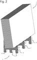
- FIG 1 schematically depicts an embodiment of the stand system 1 with three stands 3, 3', 3" carrying a stack of panels 2 like gypsum board, seem from the rear side, and figure 2 shows the setting of figure 1 from an opposite point of view.
- three stands 3, 3' and 3" are coupled using two coupling elements 4, 4'.
- a coupling element 4, 4' couples neighbouring stands 3, 3' and 3', 3" together.
- the coupling elements 4, 4' couple the stands 3, 3', 3" together to form a stable, free standing stand system 1.
- Each coupling element 4, 4' has a coupling element length 10, 10', defining a distance, holding the stands a length distance apart.
- the coupling elements 4, 4' couple the stands 3, 3', 3" in such a way as to hold them substantially parallel. Furthermore, the coupling elements 4, 4' couple in such a way as to prevent shearing of the stands 3, 3', 3", even when a load of panels is being placed in them.
- the stands 3, 3', 3" and stand system 1 can have many design aspects that may be the subject of further protection, for instance though one or more design patents.
- the coupling elements 4, 4' each have a first end with a first coupling part 8 and a second, opposite end with second coupling part 9.
- the stands 3, 3', 3" each have a coupling part receiving part 7.
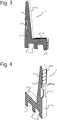
- Figure 3 and 4 show a separate stand 3 in front view and rear view, respectively.
- a stand 3 is substantially L-shaped. It has a sole 5 for resting on a floor. In the current embodiment, the lower part of the stand 3 has spaces for allowing for instance a fork of a forklift to be inserted and engage.
- the stand 3 has a rear surface 6.
- the rear surface 6 and the sole 5 usually have a mutual angle of about 85-95 degrees. Most practical is if the angle is about 90 degrees, as this allows two stands to be coupled with their rear surfaces as will be explained later on.
- the stand 3 further has a support surface 12. It here comprises a surface that has a surface roughness in order to prevent sliding of panels. Stand 3 further has a back surface 11 for backing panels that rest in the stand 3. In order to keep panels stable and prevent them from tumbling off the stand, often the support surface 12 and the back surface 11 are at an angle of 90 degrees. Furthermore, often the support surface 12 is at a slight angle with respect to the sole 5. Usually, the support surface is at an angle of between 0 and 20 degrees. The angle opens towards the front of the stand 3. The slightly backward rotated hook that is formed by the support surface 12 and the back surface 11 holds a stack of panels inclined backwards. It thus provides a kind of easel.
- the stand 3 comprises honeycomb 13.
- the honeycomb is rectangular.
- the cells run from one side to the opposite side, transverse.
- the sides define side planes that usually are parallel or functionally parallel.
- the coupling part receiving part 7 comprises a through hole.
- the through hole runs functionally transverse.
- the hole runs parallel with the cells of the honeycomb 13.
- the rear side of the wall of the hole is less wide, creating a handle.
- the rear surface 6 of the stand 3 has spaces 15 for providing name shields. Furthermore, the rear surface 6 comprises rear coupling parts 14, for coupling two stands 3 together backwards attached, with rear surfaces 6 in contact. This will be further discussed with reference to figures 7-10 .
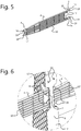
- Figure 5 shows in detail an embodiment of a coupling end for coupling two stands of figures 3 and 4
- figure 6 shows a coupling of two coupling ends to one stand.
- the coupling element 4 is here substantially plate shaped or board shaped. It has a coupling element length 10 which extends longitudinally. Here it has ribs for providing torsion stiffness. It further provides a coupling element width.
- the coupling element 4 has a first end and an opposite second end. The first end is provided with a first coupling part 8. The second end is provided with a second coupling part 9. As seen in the embodiment of figure 6 , both a first coupling part 8 and a second coupling part 9 are coupled into coupling part receiving end 7 of the stand 3. Thus, here a first and second coupling part can be coupled at the same time.
- the first coupling part of the coupling element 4 can be combined with a second, further coupling part of a similar coupling element that is placed in line with the coupling element 4.
- These coupling parts 8 and 9 thus in the depicted embodiment together form a functionally continuous groove 16, here a rectangular groove 16 with a groove bottom.
- the groove has a bottom and a groove wall 17 at the coupling element length 10 and a groove blocking wall 19 that is functionally flexible and that has a lip 18.
- the coupling parts 8, 9 can be snap-fit into the coupling part receiving part 7.
- the groove walls of the coupling parts 8, 9 when inserted into the coupling part receiving part 7 engage side walls of coupling part receiving part 7, here a transverse through hole. This in particular provides shear prevention and holds stands functionally parallel.
- the coupling parts 8, 9 provide two fingers at both sides of a center part. Other configurations are possible, like alternate fingers, or one upper and one lower part, for instance. Functionally, there are two parts that together fill the coupling part receiving part. These two parts snap-fit in said through hole..
- FIG 7 shows backwards coupling of two stands, allowing an extended stand system allowing carrying of two stacks of panels
- figure 8 shows rear coupling of stands
- figure 9 shows a step in the rear coupling of stands
- figure 10 shows stands coupled on or at their rear surfaces.
- An embodiment of the rear coupling can in fact best be seen in figure 6 .
- These two parts are horizontally in line, with the mushroom head and the slotted part aligned. Therefore, the attaching required the rotation indicated in figure 9 , resulting on rear coupling of figure 10 .
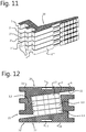
- Figure 11 shows a stack of stands, and figure 12 stacks of stands on a pallet stacking. With functionally parallel sides of the stands, the stacking is possible.
- One side of a stand is provided with blocking ends extending sideward and complementary deepened parts on its opposite side for preventing sliding of stacked stands 3, 3', 3", 3"', 3"". These blocking ends and deepened parts provide an example of anti-sliding means for preventing a stack of stand to slide.
- the L-shaped stands 3 have a stem 20 and a leg 21, said stands 3 dimensioned to allow compact stacking, for instance on a transport pallet, as depicted in figure 12 .
- Two stacks of stands, indicated 20, 20' with ends of said stems contacting or nearly contacting ends of said legs define a center space.
- that center space is filled with a stack of further stands 3, 3'.
- the stems of a first layer of stands 3 are oriented in a height direction of said space, and on that stands 3 reversed stands 3' with stems downward are positioned.
- FIGS 13 and 14 an alternative embodiment of the stands 3 is depicted in rear perspective view and in front perspective view, respectively.
- FIG 13A an alternative rear coupling provision is shown.
- first rear coupling part 23 is provided on a rear side of a stand 3 at one half, and the second, complementary rear coupling part 24 is provided on the opposite half of the rear side or rear surface 6 of a stand 3.
- the first and second rear coupling parts 23, 24 of one stand 3 work together with respective a second and first rear coupling part 24, 23 of another, similar stand 3'" that is coupled to stand 3 with their rear surfaces 6 in contact.
- the second rear coupling part 24 comprises two undercut grooves in sideward direction.
- the first rear coupling part 23 comprises opposite rails, extending in sideward direction and positioned for slidingly fitting in the undercut grooves of the second rear coupling part 24.
- a rectangular part at a distance from the rear surface 6 fits in the two opposite undercut grooves of the first rear coupling part 23.
- the first rear coupling part 23 is provided with a lip with a cam for snap-locking in the second rear coupling part 24. The lip can be manually operated for de-coupling.
- the first rear coupling part 23 here has two opposite, parallel undercut grooves that are designed to accommodate the functional part of second rear coupling part 24.
- the second rear coupling part in fact has a patch at a distance from the rear surface 6.
- the width and thickness of that patch fit into the recess with undercut grooves of the first rear coupling part 23.
- the stand 3 of figures 13 and 14 further have reinforcement ribs or reinforcing part 27.
- an inner rib runs parallel to the outer surface inside the stand, and the outer wall and this reinforcement inner rib are coupled via the same type of honeycomb described above. It was found that this provides additional strength, especially at for instance higher temperatures.
- the alternative stand 3 further comprises an attachment provision 25 for holding a removable information shield 26.
- This information shield extends above the complete stand system with plates or panels. Especially at busy building sites with many building materials provided, this makes it easier to localise the material.
- the stand 3 is provided with a simple hole for fitting a pole end of the information shield 26.
- the pallet 30 can be provided with engagement parts 31, 32, 33 which extend from the pallet surface and engage stands 3 for preventing sliding.
- engagement parts 31, 32, 33 may engage features of the stand 3, for instance engage a stacking provision of a stand that is discussed earlier.
- a coupling part engagement part 32 is positioned for engaging a coupling part receiving part 7 of a stand 3.
- FIG 15B the pallet 30 of figure 15A is depicted when provides with a first layer of stands 3, 3' in dotted lines.
- a centre engagement part 33 is provided to engage the back surfaces 11, 11' and support surfaces 12, 12' of opposite, (point)mirrored stands 3, 3'.
- engagement parts 31 are provided for engaging lower ends of stands 3, 3' and for engaging upper ends.
- centre engagement part 33 On the centre engagement part 33, further stands may be stacked in the way indicated in figure 12 .
- only four raised parts may be provided at the corners of the depicted embodiment.
- Other configurations having the same functionality are possible.
- the engagement parts effectively lock the stands 3, 3' onto the top surface of the pallet, with the stands 3, 3' in 180 degrees rotated position with respect to one another. Engagement parts engage at back surfaces, support surfaces, and at lower and upper ends of stands 3, 3'.
- the slide prevention measures can be implemented in a specially designed and produces pallet, as shown in figures 15A and 15B .
- a special floor element can be provided that can be attached to an existing pallet and that comprises the engagement parts 30 of figures 15A and 15B .
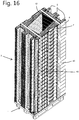
- the stands 3 are secured onto a pallet, as indicated in figure 16 .
- Figures 17 and 18 show in detail an alternative embodiment of a first and second coupling end of two similar coupling elements and a stand for coupling with the coupling ends.
- Figure 19 shows a detail of an embodiment of a coupling part receiving part 7.
- the coupling element 4 has a first end and an opposite second end.
- the first end is provided with a first coupling part 8.
- the second end is provided with a second coupling part 9.
- both a first coupling part 8 and a second coupling part 9 are couplable into coupling part receiving end 7 of the stand 3 simultaneously.
- a first and second coupling part can be coupled at the same time. It allows easy coupling of three stands 3, 3', 3" together.
- the coupling parts 8, 9 in this embodiment may each comprise at least two similar fingers.
- a finger extends axial from a centre part of the coupling element 4. Further, the finger comprises two sideway extensions spaced apart in an axial direction forming at least one groove 16, preferably two grooves 16'. In an alternative embodiment, the extensions are discs forming one continuous groove.
- the first coupling part 9 of the coupling element 4 can be combined with a second, further coupling part 8 of a similar coupling element 4' that is placed in line with the coupling element 4 forming a row of cooperating stands, as indicated in figures 17 and 18 , showing coupling in progress.
- This in particular provides shear prevention and holds stands functionally parallel.
- the coupling parts 8, 9 provide two fingers at both sides of a centre part. Other configurations are possible, like alternate fingers, or one upper and one lower part, for instance.
- Functionally there are usually at least two parts that together fill the coupling part receiving part 7. These two parts here first slide in said through insert holes 43.
- the through insert holes 43 allow passing through the sideway extension of a finger
- coupling part receiving part 7 further comprises a locking slit 44 snugly fitting around the finger part between the two sideway extensions of the finger, wherein the openings cooperate for receiving the coupling parts for allowing the functionality described above.
- the fingers are thus inserted into the insert holes 43 and then the coupling element 4 is pushed down, locking the fingers into the locking slits 44.
- This principle can also reversed, providing the stands with fingers and end surfaces of coupling elements 4 with insert holes and locking slots.
- the stand system further comprises substantially parallel side planes for allowing stacking of said stands.
- one side plane has stacking parts cooperating with complementary stacking parts on the other side plane for preventing sliding of stands when stacked.
- a stand on one side comprises extensions extending from said side plane, and on its opposite side said stand comprises corresponding indents for receiving extensions from a further, similar stand.
- one side may comprise one or more extensions and one or more indents, and the opposite side comprises corresponding indents and extensions, respectively.
- the stand system and/or the coupling element further comprise a honeycomb structure having cells running between said side planes. This increases strength en reduces weight. It facilitated easy handling of the stands and/or the coupling element.
- a wall can surround the stand.
Landscapes
- Engineering & Computer Science (AREA)
- Mechanical Engineering (AREA)
- Stackable Containers (AREA)
- Pallets (AREA)
Priority Applications (4)
| Application Number | Priority Date | Filing Date | Title |
|---|---|---|---|
| PL19171232T PL3597564T3 (pl) | 2018-07-15 | 2019-04-25 | System stojakowy do układania paneli |
| CN201921100475.2U CN211495224U (zh) | 2018-07-15 | 2019-07-15 | 用于布置面板的支架系统 |
| US16/512,297 US11167920B2 (en) | 2018-07-15 | 2019-07-15 | Stand system for arranging panels |
| PCT/NL2019/050447 WO2020017958A1 (en) | 2018-07-15 | 2019-07-15 | Stand system for arranging panels |
Applications Claiming Priority (3)
| Application Number | Priority Date | Filing Date | Title |
|---|---|---|---|
| NL2021307A NL2021307B1 (en) | 2018-07-15 | 2018-07-15 | Stand system for arranging panels |
| NL2022168 | 2018-12-10 | ||
| NL2022377A NL2022377B1 (en) | 2018-07-15 | 2019-01-11 | Stand system for arranging panels |
Publications (2)
| Publication Number | Publication Date |
|---|---|
| EP3597564A1 EP3597564A1 (en) | 2020-01-22 |
| EP3597564B1 true EP3597564B1 (en) | 2021-02-24 |
Family
ID=66290228
Family Applications (1)
| Application Number | Title | Priority Date | Filing Date |
|---|---|---|---|
| EP19171232.2A Active EP3597564B1 (en) | 2018-07-15 | 2019-04-25 | Stand system for arranging panels |
Country Status (4)
| Country | Link |
|---|---|
| US (1) | US11167920B2 (pl) |
| EP (1) | EP3597564B1 (pl) |
| PL (1) | PL3597564T3 (pl) |
| WO (1) | WO2020017958A1 (pl) |
Families Citing this family (6)
| Publication number | Priority date | Publication date | Assignee | Title |
|---|---|---|---|---|
| USD909627S1 (en) * | 2019-06-04 | 2021-02-02 | H. D. Duijts Holding B.V. | Holder for building panels |
| BE1028389B1 (nl) * | 2020-06-10 | 2022-01-18 | Deltarack Bvba | Draagrek voor het opslaan of transporteren van plaatvormige voorwerpen, combinatie van een transportpallet en een dergelijk draagrek, set onderdelen voor het vervaardigen van een dergelijk draagrek en gebruik van een dergelijk draagrek |
| CN112050047B (zh) | 2020-09-11 | 2022-06-10 | 京东方科技集团股份有限公司 | 显示装置 |
| US20220178494A1 (en) * | 2020-12-07 | 2022-06-09 | Richard M. Roche | Stand for Maintaining Panels of Sheet Material in a Vertical Orientation |
| MX2022014743A (es) * | 2021-11-24 | 2023-05-25 | Masonite Corp | Soporte de montaje de puerta adaptable para colocar e instalar un bloque de puerta y metodos de uso y ensamble del mismo. |
| JP7385331B1 (ja) * | 2023-09-14 | 2023-11-22 | 株式会社菊池空調 | 架台及び積載方法 |
Family Cites Families (18)
| Publication number | Priority date | Publication date | Assignee | Title |
|---|---|---|---|---|
| US3698577A (en) | 1970-08-21 | 1972-10-17 | Dean Research Corp | Transporting system |
| US3666115A (en) * | 1970-09-25 | 1972-05-30 | Rayson Engineering Pty Ltd | Plate storage system |
| US4382733A (en) * | 1978-11-02 | 1983-05-10 | Rodgers Kenneth G | Freight cradle with replaceable deformable cushioning insert |
| US4863024A (en) * | 1988-08-10 | 1989-09-05 | Booth Clarence R | Collapsible pallet and related products |
| US5085329A (en) | 1990-12-07 | 1992-02-04 | Crowell John W | Sheeting support |
| FR2809716B1 (fr) * | 2000-05-31 | 2002-07-26 | Saint Gobain Vitrage | Chevalet destine a la manutention et au magasinage d'ensembles de plaques |
| US6511039B1 (en) * | 2000-08-10 | 2003-01-28 | 3M Innovative Properties Company | Collapsible notebook computer platform |
| US7117997B2 (en) * | 2003-04-04 | 2006-10-10 | Thomas J. Clover | Portable material stand |
| US8141723B2 (en) * | 2006-08-18 | 2012-03-27 | Plano Molding Company | Inverted cell honeycomb structure shelving |
| NL2003884C2 (en) | 2009-11-30 | 2011-05-31 | Hh Metaal | Method, rack and cart for vertically arranging plasterboard panels for use at a workplace. |
| BE1019477A3 (nl) * | 2010-09-08 | 2012-07-03 | Parnass Bv Met Beperkte Aansprakelijkheid | Element voor het opslaan, behandelen en transporteren van voorwerpen. |
| US20140217045A1 (en) * | 2013-02-07 | 2014-08-07 | Christopher George Nesin | Apparatus for supporting automobile parts |
| BE1021416B1 (nl) * | 2013-03-26 | 2015-11-18 | Parnass, Besloten Vennootschap Met Beperkte Aansprakelijkheid | Element voor het opslaan, behandelen en transporteren van hoofdzakelijk plaatvormige voorwerpen |
| NL1040662C2 (nl) * | 2014-02-10 | 2015-08-17 | Haarmans Dongen Beheer B V | Bok voor het opstaand steunen van platen. |
| DE202014103799U1 (de) * | 2014-08-15 | 2015-11-17 | Carsten Böttcher | Transport- und/oder Lagergestell und Anordnung eines Transport- und/oder Lagergestells an einer Bodenplatte |
| DE202015005791U1 (de) * | 2015-08-19 | 2016-11-23 | Carsten Böttcher | Transport- und/oder Lagergestell |
| US10751812B2 (en) * | 2018-03-16 | 2020-08-25 | Glenn Robert Sargent | Interlocking frame for computer numerical control (CNC) |
| WO2019191075A1 (en) * | 2018-03-27 | 2019-10-03 | Roger Hansen | Skateboard stand |
-
2019
- 2019-04-25 PL PL19171232T patent/PL3597564T3/pl unknown
- 2019-04-25 EP EP19171232.2A patent/EP3597564B1/en active Active
- 2019-07-15 WO PCT/NL2019/050447 patent/WO2020017958A1/en not_active Ceased
- 2019-07-15 US US16/512,297 patent/US11167920B2/en not_active Expired - Fee Related
Non-Patent Citations (1)
| Title |
|---|
| None * |
Also Published As
| Publication number | Publication date |
|---|---|
| US11167920B2 (en) | 2021-11-09 |
| EP3597564A1 (en) | 2020-01-22 |
| PL3597564T3 (pl) | 2021-07-26 |
| US20200017295A1 (en) | 2020-01-16 |
| WO2020017958A1 (en) | 2020-01-23 |
Similar Documents
| Publication | Publication Date | Title |
|---|---|---|
| EP3597564B1 (en) | Stand system for arranging panels | |
| US6837170B2 (en) | Modular pallet | |
| CN113015681B (zh) | 顶部甲板具有索环的半尺寸塑料托板 | |
| JP2007508216A (ja) | 分解可能な一体パレットシステム | |
| US20080238277A1 (en) | Steel cabinet and locker | |
| US11731804B2 (en) | Pallet including a carrier arrangement connected to skid arrangements | |
| US9988062B2 (en) | Connectable dolly | |
| EP1009669A1 (en) | Modular pallet structure | |
| CN103298701A (zh) | 用于容纳主体外壳的壁部的护角条以及可组装和拆卸的折叠式主体外壳 | |
| US20070272640A1 (en) | Portable storage shelving | |
| US8651783B2 (en) | Storage and transportation system and elements thereof | |
| HK1007997A1 (en) | Plastic container and pallet system | |
| HK1007997B (en) | Plastic container and pallet system | |
| KR20020072351A (ko) | 판유리 운반용 적재대 | |
| EP3230172A1 (en) | A storage and display device and system | |
| US20220002028A1 (en) | Pallet made of plastic having reinforcing elements | |
| WO2016132356A1 (en) | Stackable container system | |
| NL2022377B1 (en) | Stand system for arranging panels | |
| NL2021307B1 (en) | Stand system for arranging panels | |
| WO2022253906A1 (en) | Shelve for use in a danish trolley | |
| DE202021101074U1 (de) | Displaysockel-Viertelpalettenbefestigung | |
| US20060108307A1 (en) | Merchandiser assembly | |
| RU2469932C2 (ru) | Пластмассовый поддон | |
| CZ283853B6 (cs) | Základna kontejneru | |
| KR100821067B1 (ko) | 주상형 프로파일용 파레트 |
Legal Events
| Date | Code | Title | Description |
|---|---|---|---|
| PUAI | Public reference made under article 153(3) epc to a published international application that has entered the european phase |
Free format text: ORIGINAL CODE: 0009012 |
|
| STAA | Information on the status of an ep patent application or granted ep patent |
Free format text: STATUS: THE APPLICATION HAS BEEN PUBLISHED |
|
| AK | Designated contracting states |
Kind code of ref document: A1 Designated state(s): AL AT BE BG CH CY CZ DE DK EE ES FI FR GB GR HR HU IE IS IT LI LT LU LV MC MK MT NL NO PL PT RO RS SE SI SK SM TR |
|
| AX | Request for extension of the european patent |
Extension state: BA ME |
|
| STAA | Information on the status of an ep patent application or granted ep patent |
Free format text: STATUS: REQUEST FOR EXAMINATION WAS MADE |
|
| 17P | Request for examination filed |
Effective date: 20200623 |
|
| RBV | Designated contracting states (corrected) |
Designated state(s): AL AT BE BG CH CY CZ DE DK EE ES FI FR GB GR HR HU IE IS IT LI LT LU LV MC MK MT NL NO PL PT RO RS SE SI SK SM TR |
|
| RIC1 | Information provided on ipc code assigned before grant |
Ipc: B65G 49/06 20060101ALI20200702BHEP Ipc: B65D 19/44 20060101ALN20200702BHEP Ipc: B65D 85/48 20060101AFI20200702BHEP |
|
| GRAP | Despatch of communication of intention to grant a patent |
Free format text: ORIGINAL CODE: EPIDOSNIGR1 |
|
| STAA | Information on the status of an ep patent application or granted ep patent |
Free format text: STATUS: GRANT OF PATENT IS INTENDED |
|
| INTG | Intention to grant announced |
Effective date: 20200812 |
|
| GRAS | Grant fee paid |
Free format text: ORIGINAL CODE: EPIDOSNIGR3 |
|
| GRAA | (expected) grant |
Free format text: ORIGINAL CODE: 0009210 |
|
| STAA | Information on the status of an ep patent application or granted ep patent |
Free format text: STATUS: THE PATENT HAS BEEN GRANTED |
|
| AK | Designated contracting states |
Kind code of ref document: B1 Designated state(s): AL AT BE BG CH CY CZ DE DK EE ES FI FR GB GR HR HU IE IS IT LI LT LU LV MC MK MT NL NO PL PT RO RS SE SI SK SM TR |
|
| REG | Reference to a national code |
Ref country code: CH Ref legal event code: EP |
|
| REG | Reference to a national code |
Ref country code: DE Ref legal event code: R096 Ref document number: 602019002697 Country of ref document: DE |
|
| REG | Reference to a national code |
Ref country code: AT Ref legal event code: REF Ref document number: 1364173 Country of ref document: AT Kind code of ref document: T Effective date: 20210315 |
|
| REG | Reference to a national code |
Ref country code: IE Ref legal event code: FG4D |
|
| REG | Reference to a national code |
Ref country code: DK Ref legal event code: T3 Effective date: 20210521 Ref country code: FI Ref legal event code: FGE |
|
| REG | Reference to a national code |
Ref country code: NL Ref legal event code: FP |
|
| REG | Reference to a national code |
Ref country code: NO Ref legal event code: T2 Effective date: 20210224 |
|
| REG | Reference to a national code |
Ref country code: SE Ref legal event code: TRGR |
|
| REG | Reference to a national code |
Ref country code: PT Ref legal event code: SC4A Ref document number: 3597564 Country of ref document: PT Date of ref document: 20210628 Kind code of ref document: T Free format text: AVAILABILITY OF NATIONAL TRANSLATION Effective date: 20210622 |
|
| REG | Reference to a national code |
Ref country code: LT Ref legal event code: MG9D |
|
| PG25 | Lapsed in a contracting state [announced via postgrant information from national office to epo] |
Ref country code: BG Free format text: LAPSE BECAUSE OF FAILURE TO SUBMIT A TRANSLATION OF THE DESCRIPTION OR TO PAY THE FEE WITHIN THE PRESCRIBED TIME-LIMIT Effective date: 20210524 Ref country code: HR Free format text: LAPSE BECAUSE OF FAILURE TO SUBMIT A TRANSLATION OF THE DESCRIPTION OR TO PAY THE FEE WITHIN THE PRESCRIBED TIME-LIMIT Effective date: 20210224 Ref country code: GR Free format text: LAPSE BECAUSE OF FAILURE TO SUBMIT A TRANSLATION OF THE DESCRIPTION OR TO PAY THE FEE WITHIN THE PRESCRIBED TIME-LIMIT Effective date: 20210525 Ref country code: LT Free format text: LAPSE BECAUSE OF FAILURE TO SUBMIT A TRANSLATION OF THE DESCRIPTION OR TO PAY THE FEE WITHIN THE PRESCRIBED TIME-LIMIT Effective date: 20210224 |
|
| PG25 | Lapsed in a contracting state [announced via postgrant information from national office to epo] |
Ref country code: LV Free format text: LAPSE BECAUSE OF FAILURE TO SUBMIT A TRANSLATION OF THE DESCRIPTION OR TO PAY THE FEE WITHIN THE PRESCRIBED TIME-LIMIT Effective date: 20210224 Ref country code: RS Free format text: LAPSE BECAUSE OF FAILURE TO SUBMIT A TRANSLATION OF THE DESCRIPTION OR TO PAY THE FEE WITHIN THE PRESCRIBED TIME-LIMIT Effective date: 20210224 |
|
| PG25 | Lapsed in a contracting state [announced via postgrant information from national office to epo] |
Ref country code: IS Free format text: LAPSE BECAUSE OF FAILURE TO SUBMIT A TRANSLATION OF THE DESCRIPTION OR TO PAY THE FEE WITHIN THE PRESCRIBED TIME-LIMIT Effective date: 20210624 |
|
| PG25 | Lapsed in a contracting state [announced via postgrant information from national office to epo] |
Ref country code: SM Free format text: LAPSE BECAUSE OF FAILURE TO SUBMIT A TRANSLATION OF THE DESCRIPTION OR TO PAY THE FEE WITHIN THE PRESCRIBED TIME-LIMIT Effective date: 20210224 Ref country code: EE Free format text: LAPSE BECAUSE OF FAILURE TO SUBMIT A TRANSLATION OF THE DESCRIPTION OR TO PAY THE FEE WITHIN THE PRESCRIBED TIME-LIMIT Effective date: 20210224 Ref country code: CZ Free format text: LAPSE BECAUSE OF FAILURE TO SUBMIT A TRANSLATION OF THE DESCRIPTION OR TO PAY THE FEE WITHIN THE PRESCRIBED TIME-LIMIT Effective date: 20210224 |
|
| REG | Reference to a national code |
Ref country code: DE Ref legal event code: R097 Ref document number: 602019002697 Country of ref document: DE |
|
| PG25 | Lapsed in a contracting state [announced via postgrant information from national office to epo] |
Ref country code: RO Free format text: LAPSE BECAUSE OF FAILURE TO SUBMIT A TRANSLATION OF THE DESCRIPTION OR TO PAY THE FEE WITHIN THE PRESCRIBED TIME-LIMIT Effective date: 20210224 Ref country code: SK Free format text: LAPSE BECAUSE OF FAILURE TO SUBMIT A TRANSLATION OF THE DESCRIPTION OR TO PAY THE FEE WITHIN THE PRESCRIBED TIME-LIMIT Effective date: 20210224 Ref country code: MC Free format text: LAPSE BECAUSE OF FAILURE TO SUBMIT A TRANSLATION OF THE DESCRIPTION OR TO PAY THE FEE WITHIN THE PRESCRIBED TIME-LIMIT Effective date: 20210224 |
|
| REG | Reference to a national code |
Ref country code: ES Ref legal event code: FG2A Ref document number: 2883973 Country of ref document: ES Kind code of ref document: T3 Effective date: 20211209 |
|
| PG25 | Lapsed in a contracting state [announced via postgrant information from national office to epo] |
Ref country code: LU Free format text: LAPSE BECAUSE OF NON-PAYMENT OF DUE FEES Effective date: 20210425 |
|
| PLBE | No opposition filed within time limit |
Free format text: ORIGINAL CODE: 0009261 |
|
| STAA | Information on the status of an ep patent application or granted ep patent |
Free format text: STATUS: NO OPPOSITION FILED WITHIN TIME LIMIT |
|
| PG25 | Lapsed in a contracting state [announced via postgrant information from national office to epo] |
Ref country code: AL Free format text: LAPSE BECAUSE OF FAILURE TO SUBMIT A TRANSLATION OF THE DESCRIPTION OR TO PAY THE FEE WITHIN THE PRESCRIBED TIME-LIMIT Effective date: 20210224 |
|
| 26N | No opposition filed |
Effective date: 20211125 |
|
| PG25 | Lapsed in a contracting state [announced via postgrant information from national office to epo] |
Ref country code: SI Free format text: LAPSE BECAUSE OF FAILURE TO SUBMIT A TRANSLATION OF THE DESCRIPTION OR TO PAY THE FEE WITHIN THE PRESCRIBED TIME-LIMIT Effective date: 20210224 |
|
| PG25 | Lapsed in a contracting state [announced via postgrant information from national office to epo] |
Ref country code: IS Free format text: LAPSE BECAUSE OF FAILURE TO SUBMIT A TRANSLATION OF THE DESCRIPTION OR TO PAY THE FEE WITHIN THE PRESCRIBED TIME-LIMIT Effective date: 20210624 |
|
| REG | Reference to a national code |
Ref country code: AT Ref legal event code: UEP Ref document number: 1364173 Country of ref document: AT Kind code of ref document: T Effective date: 20210224 |
|
| PG25 | Lapsed in a contracting state [announced via postgrant information from national office to epo] |
Ref country code: CY Free format text: LAPSE BECAUSE OF FAILURE TO SUBMIT A TRANSLATION OF THE DESCRIPTION OR TO PAY THE FEE WITHIN THE PRESCRIBED TIME-LIMIT Effective date: 20210224 |
|
| P01 | Opt-out of the competence of the unified patent court (upc) registered |
Effective date: 20230602 |
|
| PG25 | Lapsed in a contracting state [announced via postgrant information from national office to epo] |
Ref country code: HU Free format text: LAPSE BECAUSE OF FAILURE TO SUBMIT A TRANSLATION OF THE DESCRIPTION OR TO PAY THE FEE WITHIN THE PRESCRIBED TIME-LIMIT; INVALID AB INITIO Effective date: 20190425 |
|
| REG | Reference to a national code |
Ref country code: NL Ref legal event code: PD Owner name: GECOMA B.V.; NL Free format text: DETAILS ASSIGNMENT: CHANGE OF OWNER(S), ASSIGNMENT; FORMER OWNER NAME: H.D. DUIJTS HOLDING B.V. Effective date: 20231207 |
|
| REG | Reference to a national code |
Ref country code: DE Ref legal event code: R081 Ref document number: 602019002697 Country of ref document: DE Owner name: H.D. DUIJTS HOLDING B.V., NL Free format text: FORMER OWNER: H.D. DUIJTS HOLDING B.V., EDERVEEN, NL Ref country code: DE Ref legal event code: R081 Ref document number: 602019002697 Country of ref document: DE Owner name: GECOMA B.V., NL Free format text: FORMER OWNER: H.D. DUIJTS HOLDING B.V., EDERVEEN, NL |
|
| REG | Reference to a national code |
Ref country code: GB Ref legal event code: 732E Free format text: REGISTERED BETWEEN 20231207 AND 20231213 |
|
| REG | Reference to a national code |
Ref country code: BE Ref legal event code: PD Owner name: GECOMA B.V.; NL Free format text: DETAILS ASSIGNMENT: CHANGE OF OWNER(S), ASSIGNMENT Effective date: 20240110 |
|
| PG25 | Lapsed in a contracting state [announced via postgrant information from national office to epo] |
Ref country code: MK Free format text: LAPSE BECAUSE OF FAILURE TO SUBMIT A TRANSLATION OF THE DESCRIPTION OR TO PAY THE FEE WITHIN THE PRESCRIBED TIME-LIMIT Effective date: 20210224 |
|
| PGFP | Annual fee paid to national office [announced via postgrant information from national office to epo] |
Ref country code: IE Payment date: 20240429 Year of fee payment: 6 |
|
| PGFP | Annual fee paid to national office [announced via postgrant information from national office to epo] |
Ref country code: DK Payment date: 20240425 Year of fee payment: 6 |
|
| PGFP | Annual fee paid to national office [announced via postgrant information from national office to epo] |
Ref country code: CH Payment date: 20240501 Year of fee payment: 6 |
|
| PGFP | Annual fee paid to national office [announced via postgrant information from national office to epo] |
Ref country code: ES Payment date: 20240503 Year of fee payment: 6 |
|
| PGFP | Annual fee paid to national office [announced via postgrant information from national office to epo] |
Ref country code: AT Payment date: 20240404 Year of fee payment: 6 |
|
| PGFP | Annual fee paid to national office [announced via postgrant information from national office to epo] |
Ref country code: NO Payment date: 20240429 Year of fee payment: 6 Ref country code: IT Payment date: 20240422 Year of fee payment: 6 Ref country code: FI Payment date: 20240425 Year of fee payment: 6 |
|
| PGFP | Annual fee paid to national office [announced via postgrant information from national office to epo] |
Ref country code: PL Payment date: 20240408 Year of fee payment: 6 Ref country code: PT Payment date: 20240404 Year of fee payment: 6 |
|
| PGFP | Annual fee paid to national office [announced via postgrant information from national office to epo] |
Ref country code: TR Payment date: 20240405 Year of fee payment: 6 Ref country code: SE Payment date: 20240427 Year of fee payment: 6 |
|
| PG25 | Lapsed in a contracting state [announced via postgrant information from national office to epo] |
Ref country code: MT Free format text: LAPSE BECAUSE OF FAILURE TO SUBMIT A TRANSLATION OF THE DESCRIPTION OR TO PAY THE FEE WITHIN THE PRESCRIBED TIME-LIMIT Effective date: 20210224 |
|
| REG | Reference to a national code |
Ref country code: DE Ref legal event code: R081 Ref document number: 602019002697 Country of ref document: DE Owner name: GECOMA B.V., NL Free format text: FORMER OWNERS: GECOMA B.V., RENSWOUDE, NL; H.D. DUIJTS HOLDING B.V., EDERVEEN, NL |
|
| REG | Reference to a national code |
Ref country code: ES Ref legal event code: PC2A Owner name: GECOMA B.V. Effective date: 20241024 |
|
| REG | Reference to a national code |
Ref country code: FI Ref legal event code: PCE Owner name: GECOMA B.V. |
|
| REG | Reference to a national code |
Ref country code: NL Ref legal event code: PD Owner name: GECOMA B.V.; NL Free format text: DETAILS ASSIGNMENT: CHANGE OF OWNER(S), ASSIGNMENT; FORMER OWNER NAME: H.D. DUIJTS HOLDING B.V. Effective date: 20241220 Ref country code: GB Ref legal event code: 732E Free format text: REGISTERED BETWEEN 20241227 AND 20241231 |
|
| REG | Reference to a national code |
Ref country code: ES Ref legal event code: PC2A Owner name: GECOMA B.V. Effective date: 20250303 |
|
| REG | Reference to a national code |
Ref country code: AT Ref legal event code: PC Ref document number: 1364173 Country of ref document: AT Kind code of ref document: T Owner name: GECOMA B.V., NL Effective date: 20250203 |
|
| REG | Reference to a national code |
Ref country code: BE Ref legal event code: PD Owner name: GECOMA B.V.; NL Free format text: DETAILS ASSIGNMENT: CHANGE OF OWNER(S), ASSIGNMENT; FORMER OWNER NAME: H.D. DUIJTS HOLDING B.V. Effective date: 20241213 |
|
| PGFP | Annual fee paid to national office [announced via postgrant information from national office to epo] |
Ref country code: BE Payment date: 20250313 Year of fee payment: 7 |
|
| PGFP | Annual fee paid to national office [announced via postgrant information from national office to epo] |
Ref country code: FR Payment date: 20250221 Year of fee payment: 7 |
|
| PGFP | Annual fee paid to national office [announced via postgrant information from national office to epo] |
Ref country code: GB Payment date: 20250311 Year of fee payment: 7 |
|
| PGFP | Annual fee paid to national office [announced via postgrant information from national office to epo] |
Ref country code: NL Payment date: 20250401 Year of fee payment: 7 |
|
| PGFP | Annual fee paid to national office [announced via postgrant information from national office to epo] |
Ref country code: DE Payment date: 20250311 Year of fee payment: 7 |
|
| REG | Reference to a national code |
Ref country code: DK Ref legal event code: EBP Effective date: 20250430 |
|
| REG | Reference to a national code |
Ref country code: CH Ref legal event code: H13 Free format text: ST27 STATUS EVENT CODE: U-0-0-H10-H13 (AS PROVIDED BY THE NATIONAL OFFICE) Effective date: 20251125 |
|
| REG | Reference to a national code |
Ref country code: SE Ref legal event code: EUG |
|
| PG25 | Lapsed in a contracting state [announced via postgrant information from national office to epo] |
Ref country code: PT Free format text: LAPSE BECAUSE OF NON-PAYMENT OF DUE FEES Effective date: 20251027 |
|
| REG | Reference to a national code |
Ref country code: AT Ref legal event code: MM01 Ref document number: 1364173 Country of ref document: AT Kind code of ref document: T Effective date: 20250425 |