EP3597480B1 - Commercial vehicle, especially truck, with structure and weight measurement sensors - Google Patents
Commercial vehicle, especially truck, with structure and weight measurement sensors Download PDFInfo
- Publication number
- EP3597480B1 EP3597480B1 EP19181909.3A EP19181909A EP3597480B1 EP 3597480 B1 EP3597480 B1 EP 3597480B1 EP 19181909 A EP19181909 A EP 19181909A EP 3597480 B1 EP3597480 B1 EP 3597480B1
- Authority
- EP
- European Patent Office
- Prior art keywords
- commercial vehicle
- loader
- vehicle
- weight measurement
- measurement sensors
- Prior art date
- Legal status (The legal status is an assumption and is not a legal conclusion. Google has not performed a legal analysis and makes no representation as to the accuracy of the status listed.)
- Active
Links
- 238000005259 measurement Methods 0.000 title claims description 84
- 238000012545 processing Methods 0.000 claims description 28
- 230000005484 gravity Effects 0.000 claims description 16
- 238000004891 communication Methods 0.000 claims description 10
- 238000000034 method Methods 0.000 description 6
- 239000003086 colorant Substances 0.000 description 5
- 238000010276 construction Methods 0.000 description 4
- 238000011161 development Methods 0.000 description 3
- 230000018109 developmental process Effects 0.000 description 3
- 230000012447 hatching Effects 0.000 description 2
- 230000003287 optical effect Effects 0.000 description 2
- 241001074710 Eucalyptus populnea Species 0.000 description 1
- 230000000712 assembly Effects 0.000 description 1
- 238000000429 assembly Methods 0.000 description 1
- 230000005540 biological transmission Effects 0.000 description 1
- 238000004040 coloring Methods 0.000 description 1
- 230000001419 dependent effect Effects 0.000 description 1
- 238000001514 detection method Methods 0.000 description 1
- 238000006073 displacement reaction Methods 0.000 description 1
- 238000012544 monitoring process Methods 0.000 description 1
Images


Classifications
-
- G—PHYSICS
- G01—MEASURING; TESTING
- G01G—WEIGHING
- G01G19/00—Weighing apparatus or methods adapted for special purposes not provided for in the preceding groups
- G01G19/08—Weighing apparatus or methods adapted for special purposes not provided for in the preceding groups for incorporation in vehicles
-
- B—PERFORMING OPERATIONS; TRANSPORTING
- B60—VEHICLES IN GENERAL
- B60P—VEHICLES ADAPTED FOR LOAD TRANSPORTATION OR TO TRANSPORT, TO CARRY, OR TO COMPRISE SPECIAL LOADS OR OBJECTS
- B60P1/00—Vehicles predominantly for transporting loads and modified to facilitate loading, consolidating the load, or unloading
- B60P1/64—Vehicles predominantly for transporting loads and modified to facilitate loading, consolidating the load, or unloading the load supporting or containing element being readily removable
- B60P1/6418—Vehicles predominantly for transporting loads and modified to facilitate loading, consolidating the load, or unloading the load supporting or containing element being readily removable the load-transporting element being a container or similar
-
- B—PERFORMING OPERATIONS; TRANSPORTING
- B62—LAND VEHICLES FOR TRAVELLING OTHERWISE THAN ON RAILS
- B62D—MOTOR VEHICLES; TRAILERS
- B62D21/00—Understructures, i.e. chassis frame on which a vehicle body may be mounted
- B62D21/09—Means for mounting load bearing surfaces
-
- B—PERFORMING OPERATIONS; TRANSPORTING
- B62—LAND VEHICLES FOR TRAVELLING OTHERWISE THAN ON RAILS
- B62D—MOTOR VEHICLES; TRAILERS
- B62D33/00—Superstructures for load-carrying vehicles
- B62D33/04—Enclosed load compartments ; Frameworks for movable panels, tarpaulins or side curtains
Definitions
- the invention relates to a commercial vehicle, preferably a truck, with a body, a vehicle frame and weight measurement sensors.
- the DE 10 2011 080 245 A1 relates to a method for monitoring an additional load on a loading area of a vehicle, the method having a step of determining an additional load information of the additional load on the loading area by means of at least one weight signal.
- the weight signal represents a signal from a weight sensor arranged on the loading area.
- the DE 10 2016 219 176 A1 relates to a transport vehicle or a group of transport vehicles with a loading area and with at least one load detection unit which is designed to detect the weight of a load on the loading area.
- the object of the invention is to create an alternative and/or improved technique for measuring the weight of a commercial vehicle with a body.
- the utility vehicle is preferably a truck.
- the utility vehicle has a structure for loading cargo and a vehicle body frame (e.g., comprising at least two parallel vehicle rails or other structure that supports the body).
- a plurality of weight measurement sensors e.g. with an optical, electronic and/or mechanical operating principle
- the structure is subsequently placed on the vehicle main frame with the preassembled plurality of weight measurement sensors (eg on the weight measurement sensors).
- the utility vehicle has a display device.
- the display device is for displaying weight measurements load states of the different sections of the body determined by the plurality of weight measurement sensors and/or a center of gravity of a load of a load of the body determined by weight measurements of the plurality of weight measurement sensors and/or by axle loads of the commercial vehicle determined by weight measurements of the plurality of weight measurement sensors (e.g. the display device is correspondingly controlled by a processing unit for such a display).
- the commercial vehicle offers the possibility that the commercial vehicle with an identical structure with regard to the vehicle main frame and weight measuring sensors can be used for a large number of different superstructures.
- the commercial vehicle can be set up ready for operation by a commercial vehicle manufacturer, including the pre-assembled weight measurement sensors. After that, for example, a specialized body manufacturer can place any body desired by the customer on the vehicle main frame.
- Load states can be determined in several sections of a large number of different structures by measuring the pre-assembled weight measurement sensors. It is not necessary for the bodybuilder to develop his own load measurement system and adapt it for each body type.
- the weight measurement sensors can be integrated into the main vehicle frame and/or arranged on an upper side of the main vehicle frame. It is possible for the weight measurement sensors to be fixed to the main vehicle frame.
- the loading states and/or the center of gravity can preferably be determined by means of a processing unit.
- the processing unit can be in communication with the weight measurement sensors and/or the display device.
- a displayed size and/or number of areas can be set and/or changed by a user. For example, multiple areas can be merged for convenience, etc.
- the plurality of weight measurement sensors are body-independent on the vehicle's main frame for use with a variety of different bodies (e.g., including open bodies (e.g., dump and dump bodies) and/or closed bodies (e.g., box bodies) ) pre-assembled for subsequent attachment to the vehicle main frame.
- the structure consists of a group of a plurality of structures, preferably of different structure types, for example comprising at least one open structure (e.g. tipper or trough structure) and at least one closed structure (e.g. box structure), preferably wherein the plurality of structures is designed to be placed on the main vehicle frame and for use with the plurality of weight measurement sensors.
- the plurality of weight measuring sensors are arranged at connection points of the vehicle main frame to the body, preferably at least at four outer corner points of a connection to the body (e.g. front and rear; left and right, for example at at least six connection points (e.g. front, middle and rear; each left and right, optionally e.g. additionally in the middle).
- the utility vehicle has an electrical or electronic body interface in communication with the plurality of weight measurement sensors for providing the measurement signals of the plurality of weight measurement sensors by means of the electrical or electronic body interface (e.g. directly or indirectly (e.g. processed or forwarded, e.g. by processing unit)).
- the electrical or electronic body interface e.g. directly or indirectly (e.g. processed or forwarded, e.g. by processing unit)
- This enables the weight measurements or load states to be transmitted to a processing unit of the body and/or a display unit of the body.
- the body manufacturer can thus, for example, provide type-specific one or more loader display units on or in the body or vehicle, which can be viewed by a loader during a typical loading process according to the type of body.
- the body interface may be preassembled, for example by the manufacturer of the commercial vehicle, before the body is placed on the vehicle main frame, for example by the body manufacturer.
- the electrical or electronic body interface prefferably be arranged in a driver's cab of the commercial vehicle and/or on the vehicle main frame underneath the body.
- the display device has at least one loader display unit (e.g. permanently installed or mobile) which is arranged outside a driver's cab of the commercial vehicle, preferably visible to a loader loading the body.
- loader display unit e.g. permanently installed or mobile
- the at least one loader display unit is in communication with the body interface to receive the measurement signals from the plurality of weight measurement sensors (e.g. directly or indirectly (for example forwarded or processed by a processing unit)).
- a plurality of loader display units arranged in a distributed manner are provided, which preferably each display a loading status of an assigned section of the body and/or respective loading states of a plurality of assigned sections of the body. This can make it possible, for example, for at least one loader display unit to be provided for different loading processes and/or for at least one loader display unit to be visible to the loader depending on the position of the loader.
- a loader display unit which preferably displays the loading states of several or all sections of the body. This allows an overview of several or all sections of the structure to be provided in one place.
- the body is an enclosed body, preferably a box body and/or a canvas body with a fixed ceiling
- the at least one loader display unit is mounted (e.g., internally) on a ceiling (e.g., a rear portion of the Ceiling with respect to a forward direction of the commercial vehicle) (and / or z. B. on a side wall) of the structure arranged.
- a ceiling e.g., a rear portion of the Ceiling with respect to a forward direction of the commercial vehicle
- the loader display unit can still be viewed, for example, when the body is (almost) fully loaded.
- the body is an open body, preferably a tipper and/or a dump body, and the at least one loader display unit is arranged on both longitudinal outer sides of the body (e.g. a first loader display unit is on a first longitudinal outer side of the body and a second loader display unit is disposed on an opposite second longitudinal outside of the body).
- At least one loader display unit on a rear side of the body.
- a driver of an excavator or wheel loader can recognize the loading status of the body during loading and continue to load the body accordingly.
- the body is a tarpaulin-covered body, preferably a flatbed body with the tarpaulin, and the at least one loader display unit is arranged on ribs of the body and/or supporting elements of a body covering, preferably for viewing from both the inside and to be visible from the outside when the tarpaulin is folded up and/or removed.
- the structure is an open structure, preferably a flatbed structure and/or a platform structure, and the at least one loader display unit is arranged on a front wall of the structure and/or an outer rear wall of a driver's cab of the utility vehicle.
- the structure is an open, multi-storey structure, preferably a vehicle transporter structure, and the at least one loader display unit is arranged on the inside of structure parts and/or holders at eye level for the loader sitting in the vehicle to be loaded.
- the structure is a closed structure, preferably a tank and/or silo structure, and the at least one loader display unit is arranged on both longitudinal outer sides of the structure and/or at a filling opening of the structure.
- the at least one loader display unit is arranged (e.g. fastened) on the outside and/or visible from the outside of the utility vehicle, preferably the body.
- the display device has a preferably high-resolution driver's cab display unit arranged in a driver's cab of the utility vehicle.
- the display device preferably has both the at least one loader display unit and the driver's cab display unit.
- the display device may have a mobile display unit, for example a smartphone or a tablet computer.
- the utility vehicle has a processing unit which is designed to receive the measurement signals from the plurality of weight measurement sensors and to output output signals to the display device.
- the processing unit preferably compares the measurement signals with a predetermined and/or adjustable legally permissible limit and outputs a corresponding output signal (ie corresponding to a result of the comparison) from the display device.
- the processing unit also compares the measurement signals from the plurality of weight measurement sensors with a predetermined technically permissible limit value, which is higher than the legally permissible limit value, and outputs a corresponding output signal to the display device.
- the processing unit additionally compares the measurement signals from the plurality of weight measurement sensors with a further predetermined technically permissible limit value, which is higher than the technically permissible limit value, and outputs a corresponding output signal to the display device.
- the utility vehicle has a camera device which is arranged to record the different sections of the structure.
- Output signals are preferably output from the processing unit to the display device, for example, in such a way that the determined loading states of the different sections of the body are superimposed according to the different sections in a recording (e.g. real-time recording) of the camera device and/or the determined center of gravity is a recording ( e.g. real-time recording) is superimposed on the camera device.
- the load states determined are each represented by a combination of a number of illuminated symbols and a color of the illuminated symbols on the display device.
- display options on the display device have a representation of each section and together with previously initially determined unladen weights of the vehicle and the axle loads determined therefrom, each both as an absolute weight value and with color coding.
- a display with colored lights can be useful if, for example, the exact weight of the filling of the loading shovel cannot be determined when loading with a wheel loader.
- a limit value e.g. legally permissible limit value
- the commercial vehicle has a trailer and/or semi-trailer interface for receiving weight measurements of a load on a trailer or semi-trailer for display on the display device.
- the commercial vehicle has a communication interface for communicating with an external computer system, preferably a fleet management system, for transmitting the determined loading conditions and/or the determined center of gravity and/or the determined axle loads.
- FIGS. 1 and 2 show a commercial vehicle 10 configured as a truck.
- the commercial vehicle 10 has a main vehicle frame 12 , a driver's cab 14 and a body 16 .
- the main vehicle frame 12 is formed, for example, by two parallel longitudinal members which are connected to one another by a plurality of cross members.
- the vehicle main frame 12 extends in a longitudinal direction of the utility vehicle 10.
- the vehicle main frame 12 supports the driver's cab 14.
- the vehicle main frame 12 supports the body 16.
- the driver's cab 14 has a driver's workplace for a driver of the utility vehicle 10 .
- the driver's cab 14 is arranged in front of the body 16 in a longitudinal direction of the utility vehicle 10 .
- the driver's cab 14 can, for example, be mounted on the vehicle main frame 12 such that it can be tilted.
- the structure 16 is designed to accommodate cargo that is to be transported by the utility vehicle 10 .
- the structure 16 can be closed on all sides and, for example, have one or more doors for loading and unloading, e.g. B. Box body.
- the structure 16 can, for. B. also be open at the top for loading and unloading, z. B. trough body or tipper body.
- a plurality of weight measurement sensors 18 are already preinstalled on the main vehicle frame 12 before the assembly 16 is installed.
- the weight measurement sensors 18 are in particular pre-mounted on the vehicle main frame 12 independently of the structure, e.g. B. integrated into this.
- the weight sensors 18 can be used with a variety of different assemblies 16. This is relevant because the superstructures 16 are typically manufactured by specialized body manufacturers and are mounted without a body on a commercial vehicle 10 that has already been manufactured by a commercial vehicle manufacturer ready for operation.
- the weight measuring sensors 18 can be arranged on an upper side of the vehicle main frame 12, e.g. B. for arrangement at predetermined connection points to the structure 16. As shown, the weight measurement sensors can thus be arranged in principle between the vehicle main frame 12 and the structure 16.
- the plurality of weight measuring sensors 18 are distributed on the vehicle main frame 12 such that different sections of the body 16 can be monitored.
- weight measuring sensors 18 can be arranged at least at all four corners of the connection of the body 16, for example on longitudinal members or cross members of the vehicle main frame 12.
- a first weight measuring sensor 18 can be positioned at the front of, preferably on, a first longitudinal member of the commercial vehicle 10 with respect to a forward direction of travel of the commercial vehicle 10 Vehicle main frame 12 may be arranged.
- a second weight measuring sensor 18 can be arranged at the rear of, preferably on, the first side member with respect to the forward direction of travel.
- a third weight measuring sensor 18 can be arranged at the front, preferably on, a second longitudinal beam of the vehicle main frame 12 with respect to the forward direction of travel of the utility vehicle.
- a fourth weight measuring sensor 18 can be arranged at the rear of, preferably on, the second side member with respect to the forward direction of travel. It is also possible for the first and third weight measurement sensors 18 to be arranged at, preferably on, opposite ends of a front cross member of the vehicle main frame 12 and/or for the second and fourth weight measurement sensors 18 to be arranged at opposite ends of a rear cross member of the vehicle main frame. As shown, six weight measuring sensors 18, for example, can also be provided, preferably for measuring two front (left and right), two middle (left and right) and two rear (left and right) sections of the structure 16.
- the measurement accuracy can be increased by increasing the number of weight measurement sensors 18 and selecting the respective position of the additional weight measurement sensors 18 to match the connection points of the body 16 to the vehicle main frame 12, such as bridge attachment brackets.
- the weight measurement sensors 18 can carry out a weight force measurement on the structure 16 according to any known principle.
- the weight measurement sensors 18 can be embodied as pressure sensors, optical sensors, electronic sensors, and so on.
- the measurement by the weight measurement sensors 18 can be carried out with a reasonable accuracy, for example depending on the load, possibly also depending on the application with adjustable weight tolerance ranges.
- the weight measuring sensors 18 can output electrical signals that indicate a measured weight force, which can be displayed, for example, processed or unprocessed by a display device 24, 28.
- the weight measurement sensors 18 may be in communication with a processing unit 22 for transmitting the electrical signals.
- the processing unit 22 is, for example, initially calibrated with respect to the structure 16 in order to determine an empty weight of the structure 16 and permissible limits for the load weight in the structure 16 .
- information on the weights of commercial vehicle 10, body 16, axle load distribution (in the assembled state) etc. can be determined and stored in a corresponding memory of processing unit 22.
- the processing unit 22 can then access these values in its calculation logic for the loading conditions and the center of gravity.
- the processing unit 22 may determine the load conditions of the different monitored portions of the structure 16 based on the electrical signals from the weight measurement sensors 18 .
- the processing unit 22 may further determine a center of gravity of the load of the body 16 based on the electrical signals from the weight measurement sensors 18 .
- the processing unit 22 can, for example, control a driver's cab display unit 24 to display the load states of the different sections and/or the center of gravity of the body 16 . This allows a user in the cab, z. B. the driver of the commercial vehicle 10, about the loading status of each monitored section of the body 16 and the focus of the load are informed.
- the driver's cab display unit 24 can have, for example, a high-resolution display (for example an LCD display), preferably a secondary display in or on the center console, preferably outside of the instrument cluster behind a steering wheel in the driver's cab.
- a high-resolution display for example an LCD display
- secondary display in or on the center console, preferably outside of the instrument cluster behind a steering wheel in the driver's cab.
- the weight measurement sensors 18 may also be connected to an electronic body interface 26 directly or indirectly, for example via the processing unit 22 .
- the electronic body interface 26 can be provided by the manufacturer of the commercial vehicle 10 (without body) in order to provide a communication interface for the manufacturer of the body 16 via which the relevant data from the weight measuring sensors 18 can be called up.
- the electronic body interface 26 can be a standardized interface from the manufacturer. This means that 16 the information regarding the weight measurements of the weight measuring sensors 18 (for example loading conditions of the individual sections and/or the center of gravity of the loading of the structure 16) can be called up for further use. In particular, this allows the body manufacturer to arrange their own loader display units 28 on the commercial vehicle 10, preferably in or on the outside of the body 16. In this way, one or more loader display units 28 for informing loaders of the structure 16 can be provided in a structure-specific manner, ie depending on the type and size of the structure 16 .
- the loader display unit or units 28 are preferably arranged in such a way that they are clearly visible to the loader in accordance with the respective type and the respective size of the structure 16 when the respective structure 16 is loaded as intended.
- these can be distributed on the outside or in the structure 16 and can be provided redundantly, that is to say in each case designed in a similar or identical manner or displaying similar or identical information. This makes it possible, for example, for the loader to see directly during the loading process which weight has already been loaded, which weight can still be loaded and/or how the weight is distributed. By recognizing the distribution of the weight, it is also possible to continue loading in a targeted manner. In this way, the existing loading space in the body 16 can be used as effectively as possible and correct axle load distribution can be ensured.
- FIG. 1 and 2 show a trough or tipper body 16 .
- This body 16 is usually loaded from a longitudinal side of the body 16, for example by a wheel loader, an excavator, etc.
- the loader display units 28 can be arranged here, for example, on both longitudinal outer sides of the body 16 so that they are clearly visible to the driver of the wheel loader or excavator etc. from the outside while the body 16 is being loaded.
- the loader display units 28 may extend along substantially an entire length of the body 16 (as shown) or may be located on the longitudinal outer sides of the body 16 in only a portion, for example forward, center, or rear.
- An alternative or additional loader display unit can be arranged on a rear side of the superstructure 16, for example.
- the body 16 is formed as a box body, in which the loader display unit is arranged in particular in the body 16 on a ceiling of the body 16 . It is also possible alternative or to arrange additional display units inside or outside of the structure 16 on side walls, on the floor, on one or more doors of the structure 16.
- a mobile display unit can be provided in addition or as an alternative, which communicates, for example, wirelessly or with a cable with the processing unit 22 for displaying the measured loading states and/or the center of gravity.
- the mobile display unit can be in the form of a tablet computer or a smartphone.
- a user interface (not shown), e.g. B. for the driver and / or the loader is provided.
- the size and number of monitored areas can be changed via the user interface.
- separately monitored areas can be combined into a single area in certain use cases.
- the areas can be parameterized. Such settings can, for example, also be changeable or unchangeable by the body manufacturer himself.
- the display units 24, 28 are to be designed in such a way that they can be seen in any loading condition, day or night, even in direct sunlight.
- the weight measurement sensors 18 can carry out the weight measurements both when the motor vehicle is stationary and when it is moving.
- the display units 24, 28 can display the weight in the individual sections of the structure 16 and the center of gravity of the load in the structure 16, for example continuously at any time, both when stationary and while driving.
- a display while driving by the driver's cab display units 24 also makes it possible, for example, for undesired load displacements to be detected while driving, which can be caused, for example, by insufficient load securing.
- the commercial vehicle prefferably has an electronic trailer and/or semi-trailer interface 29 for receiving weight measurements of a load on a trailer or semi-trailer for display on the display unit 24 and/or 28 .
- a communication interface 31 can be provided for communication with an external computer system, preferably a fleet management system, for transmission of the ascertained loading states and/or the ascertained center of gravity.
- the loading information can be transmitted to a freight forwarder or vehicle operator will. This can, for example, identify potentially additional loading capacity at any time during a tour, etc.
- the display by the display units 24, 28 may include, for example, a graphic display of the entire vehicle with information on the actual individual weights of the load, the weight measuring sensors 18, or colored lights, or a combination thereof, as with reference to FIG Figures 3A to 4B is described.
- a camera device 30 (see figure 1 ) is arranged, for example, on the structure 16, which receives the structure 16, for example in real time.
- the camera device 30 may preferably be arranged to capture the various portions of the structure 16 associated with the weight measurement sensors 18 .
- the display units 24, 28 can superimpose the determined loading states and/or the determined center of gravity of a recording (e.g. real-time recording, for example a moving image) of the camera device 30.
- auxiliary lines for the loading sections to be superimposed on the recording and, for example, color information for the respective loading sections to be displayed. For example, colored illuminated symbols can be displayed for each loading area, or the loading areas can each be colored across the board, depending on the respective loading status.
- the center of gravity determined can be superimposed on the recording of the camera device 30 in a correct perspective.
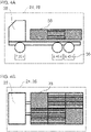
- Figures 3A to 4B show different exemplary representations of a graphic display on the display unit 24 and/or 28.
- the display is here both in side view ( Figure 3A , 4A ) as well as in top view ( Figures 3B , 4B ) shown.
- a pictogram 32 that graphically represents the commercial vehicle 10 is displayed.
- a color display e.g. traffic light
- the number of color displays 34 can also be smaller or larger than the number shown here.
- alphanumeric displays 36 relating to the respective axle loads can also be displayed, which can be determined, for example, from the weight measurements of the weight measuring sensors 18, e.g. B. from the processing unit 22.
- the display can be made more detailed (not shown separately) by means of illuminated symbols which are assigned to the monitored areas. For example, a number of symbols that light up and their coloring can be used to display a load status in the assigned area in a way that the observer can understand.
- 1 green light between 0% and 20% of the legal load limit.
- 2 green lights charged between 20% and 40% of the legal limit.
- 3 green lights charged between 40% and 60% of the legal limit.
- 4 green lights charged between 60% and 80% of the legal limit.
- 4 green lights and 1 yellow light charged between 80% and 100% of the legal limit.
- 4 green lights and 1 yellow light and 1 red light charged between 100% and 115% of the legal limit and/or between 0% and 50% of the range between the legal and technical limits.
- 4 green lights and 1 yellow light and 2 red lights charged between 115% and 130% of the legal limit and/or between 50% and 100% of the range between the legal and technical limits.
- the background to this detailed display option may be that there is more than one limit to the payload for a commercial vehicle. Instead, for example, a legally permissible limit for operation on public roads, a technically permissible limit for operation on non-public roads and in some cases also a higher or further technically permissible limit with operating restrictions for the commercial vehicle 10, e.g. operation only at reduced vehicle speed, so that an adapted, differentiated display can be useful here and offers added value. In addition, with such a differentiated display there is also the possibility of recognizing how much has to be unloaded or reloaded if necessary in order not to exceed a target limit when loading.
- the legally permissible limit value(s), the technically permissible limit value(s) and the further or higher technically permissible limit value(s) can be stored, for example, in a memory of the processing unit 22 .
- the processing unit 22 can control the display units 24, 28 in accordance with one or more comparisons of the load states determined by the weight measurement sensors with the limit value(s).
- the monitored areas in the structure 16 can be shown as segments 38 in addition to the utility vehicle pictogram 32 .
- the segments 38 can be of different colors, e.g. red, yellow, green, colored according to the respective load status of the area or segment. Different hatching can correspond to different colors.
Description
Die Erfindung betrifft ein Nutzfahrzeug, vorzugsweise einen Lastkraftwagen, mit einem Aufbau, einem Fahrzeugrahmen und Gewichtsmesssensoren.The invention relates to a commercial vehicle, preferably a truck, with a body, a vehicle frame and weight measurement sensors.
Aus der
Die
Die
Der Erfindung liegt die Aufgabe zu Grunde, eine alternative und/oder verbesserte Technik bezüglich einer Gewichtsmessung bei einem Nutzfahrzeug mit Aufbau zu schaffen.The object of the invention is to create an alternative and/or improved technique for measuring the weight of a commercial vehicle with a body.
Die Aufgabe wird gelöst durch die Merkmale des unabhängigen Anspruchs 1. Vorteilhafte Weiterbildungen sind in den abhängigen Ansprüchen und der Beschreibung angegeben.The object is achieved by the features of independent claim 1. Advantageous developments are specified in the dependent claims and the description.
Das Nutzfahrzeug ist vorzugsweise ein Lastkraftwagen. Das Nutzfahrzeug weist einen Aufbau zum Laden von Ladegut und einen Fahrzeughauptrahmen (z. B. umfassend mindestens zwei parallele Fahrzeughauptlängsträger oder eine andere Struktur, welche den Aufbau trägt) auf. An dem Fahrzeughauptrahmen ist eine Mehrzahl von Gewichtsmesssensoren (z. B. mit optischem, elektronischem und/oder mechanischem Wirkprinzip) vormontiert und zur Gewichtsmessung unterschiedlicher Abschnitte (z. B. Bodenabschnitte oder Hilfsrahmenabschnitte) des Aufbaus verteilt angeordnet (z. B. unter einem Boden des Aufbaus). Der Aufbau ist nachträglich auf den Fahrzeughauptrahmen mit der vormontierten Mehrzahl von Gewichtsmesssensoren aufgesetzt (z. B. auf die Gewichtsmesssensoren). Das Nutzfahrzeug weist eine Anzeigeeinrichtung auf. Die Anzeigeeinrichtung ist zur Anzeige von durch Gewichtsmessungen der Mehrzahl von Gewichtsmesssensoren ermittelten Beladungszuständen der unterschiedlichen Abschnitte des Aufbaus und/oder eines durch Gewichtsmessungen der Mehrzahl von Gewichtsmesssensoren ermittelten Ladungsschwerpunktes einer Beladung des Aufbaus und/oder von durch Gewichtsmessungen der Mehrzahl von Gewichtsmesssensoren ermittelten Achslasten des Nutzfahrzeugs ausgebildet (z. B. wird die Anzeigeeinrichtung zu einer solchen Anzeige entsprechend von einer Verarbeitungseinheit gesteuert).The utility vehicle is preferably a truck. The utility vehicle has a structure for loading cargo and a vehicle body frame (e.g., comprising at least two parallel vehicle rails or other structure that supports the body). A plurality of weight measurement sensors (e.g. with an optical, electronic and/or mechanical operating principle) are pre-installed on the main vehicle frame and arranged in a distributed manner (e.g. under a floor) for measuring the weight of different sections (e.g. floor sections or auxiliary frame sections) of the body of construction). The structure is subsequently placed on the vehicle main frame with the preassembled plurality of weight measurement sensors (eg on the weight measurement sensors). The utility vehicle has a display device. The display device is for displaying weight measurements load states of the different sections of the body determined by the plurality of weight measurement sensors and/or a center of gravity of a load of a load of the body determined by weight measurements of the plurality of weight measurement sensors and/or by axle loads of the commercial vehicle determined by weight measurements of the plurality of weight measurement sensors (e.g. the display device is correspondingly controlled by a processing unit for such a display).
Das Nutzfahrzeug bietet durch die Vormontage der Gewichtsmesssensoren am Fahrzeughauptrahmen die Möglichkeit, dass das Nutzfahrzeug mit identischer Struktur hinsichtlich Fahrzeughauptrahmen und Gewichtsmesssensoren für eine Vielzahl von unterschiedlichen Aufbauten verwendbar ist. Das Nutzfahrzeug kann betriebsbereit von einem Nutzfahrzeughersteller inklusive der vormontierten Gewichtsmesssensoren aufgebaut werden. Danach kann bspw. ein spezialisierter Aufbauhersteller irgendeinen vom Kunden gewünschten Aufbau auf den Fahrzeughauptrahmen aufsetzen. Durch Messungen der vormontierten Gewichtsmesssensoren können somit Beladungszustände in mehreren Abschnitten einer Vielzahl unterschiedlicher Aufbauten ermittelt werden. Es ist nicht notwendig, dass der Aufbauhersteller ein eigenes Beladungsmesssystem entwickelt und für jeden Aufbautyp anpasst.Due to the pre-assembly of the weight measuring sensors on the vehicle main frame, the commercial vehicle offers the possibility that the commercial vehicle with an identical structure with regard to the vehicle main frame and weight measuring sensors can be used for a large number of different superstructures. The commercial vehicle can be set up ready for operation by a commercial vehicle manufacturer, including the pre-assembled weight measurement sensors. After that, for example, a specialized body manufacturer can place any body desired by the customer on the vehicle main frame. Load states can be determined in several sections of a large number of different structures by measuring the pre-assembled weight measurement sensors. It is not necessary for the bodybuilder to develop his own load measurement system and adapt it for each body type.
Beispielsweise können die Gewichtsmesssensoren in den Fahrzeughauptrahmen integriert sein und/oder an einer Oberseite des Fahrzeughauptrahmens angeordnet sein. Es ist möglich, dass die Gewichtsmesssensoren fahrzeughauptrahmenfest ausgebildet sind.For example, the weight measurement sensors can be integrated into the main vehicle frame and/or arranged on an upper side of the main vehicle frame. It is possible for the weight measurement sensors to be fixed to the main vehicle frame.
Vorzugsweise können die Beladungszustände und/oder der Schwerpunkt mittels einer Verarbeitungseinheit ermittelt werden. Vorzugsweise kann die Verarbeitungseinheit in Kommunikationsverbindung mit den Gewichtsmesssensoren und/oder der Anzeigeeinrichtung stehen.The loading states and/or the center of gravity can preferably be determined by means of a processing unit. Preferably, the processing unit can be in communication with the weight measurement sensors and/or the display device.
Es ist möglich, dass eine angezeigte Größe und/oder Anzahl der Bereiche von einem Benutzer einstellbar und/oder veränderbar ist. Zum Beispiel können mehrere Bereiche zur Vereinfachung zusammengelegt werden usw.It is possible that a displayed size and/or number of areas can be set and/or changed by a user. For example, multiple areas can be merged for convenience, etc.
In einem Ausführungsbeispiel ist die Mehrzahl von Gewichtsmesssensoren aufbauunabhängig an dem Fahrzeughauptrahmen zur Verwendung mit einer Vielzahl von unterschiedlichen Aufbauten (z. B. umfassend offene Aufbauten (z. B. Kipper- und Muldenaufbauten) und/oder geschlossene Aufbauten (z. B. Kofferaufbauten)) zum nachträglichen Aufsetzen auf den Fahrzeughauptrahmen vormontiert. Alternativ oder zusätzlich ist der Aufbau aus einer Gruppe von einer Mehrzahl von Aufbauten, vorzugsweise von unterschiedlichen Aufbautypen, beispielsweise umfassend mindestens einen offenen Aufbau (z. B. Kipper- oder Muldenaufbau) und mindestens einen geschlossenen Aufbau (z. B. Kofferaufbau), ausgewählt, wobei vorzugsweise die Mehrzahl von Aufbauten zum Aufsetzen auf den Fahrzeughauptrahmen und zur Verwendung mit der Mehrzahl von Gewichtsmesssensoren ausgebildet ist.In one embodiment, the plurality of weight measurement sensors are body-independent on the vehicle's main frame for use with a variety of different bodies (e.g., including open bodies (e.g., dump and dump bodies) and/or closed bodies (e.g., box bodies) ) pre-assembled for subsequent attachment to the vehicle main frame. Alternatively or additionally, the structure consists of a group of a plurality of structures, preferably of different structure types, for example comprising at least one open structure (e.g. tipper or trough structure) and at least one closed structure (e.g. box structure), preferably wherein the plurality of structures is designed to be placed on the main vehicle frame and for use with the plurality of weight measurement sensors.
In einem weiteren Ausführungsbeispiel ist die Mehrzahl von Gewichtsmesssensoren an Anbindungspunkten des Fahrzeughauptrahmens zum Aufbau angeordnet, vorzugsweise zumindest an vier äußeren Eckpunkten einer Anbindung des Aufbaus (zum Beispiel vorne und hinten; jeweils links und rechts, beispielsweise an zumindest sechs Anbindungspunkten (zum Beispiel vorne, mittig und hinten; jeweils links und rechts, optional bspw. zusätzlich mittig).In a further exemplary embodiment, the plurality of weight measuring sensors are arranged at connection points of the vehicle main frame to the body, preferably at least at four outer corner points of a connection to the body (e.g. front and rear; left and right, for example at at least six connection points (e.g. front, middle and rear; each left and right, optionally e.g. additionally in the middle).
In einem weiteren Ausführungsbeispiel weist das Nutzfahrzeug eine elektrische oder elektronische Aufbau-Schnittstelle in Kommunikationsverbindung mit der Mehrzahl von Gewichtsmesssensoren zum Bereitstellen der Messsignale der Mehrzahl von Gewichtsmesssensoren mittels der elektrischen oder elektronischen Aufbau-Schnittstelle auf (z. B. direkt oder indirekt (z.B. verarbeitet oder weitergeleitet, z. B. durch Verarbeitungseinheit)). Dies ermöglicht, dass die Gewichtsmessungen bzw. Beladungszustände zu einer Verarbeitungseinheit des Aufbaus und/oder einer Anzeigeeinheit des Aufbaus übertragen werden. Damit kann der Aufbauhersteller beispielsweise typspezifisch eine oder mehrere Belader-Anzeigeeinheiten am oder im Aufbau oder Fahrzeug vorsehen, die entsprechend dem Typ des Aufbaus von einem Belader während eines typischen Beladungsvorgangs eingesehen werden können.In a further exemplary embodiment, the utility vehicle has an electrical or electronic body interface in communication with the plurality of weight measurement sensors for providing the measurement signals of the plurality of weight measurement sensors by means of the electrical or electronic body interface (e.g. directly or indirectly (e.g. processed or forwarded, e.g. by processing unit)). This enables the weight measurements or load states to be transmitted to a processing unit of the body and/or a display unit of the body. The body manufacturer can thus, for example, provide type-specific one or more loader display units on or in the body or vehicle, which can be viewed by a loader during a typical loading process according to the type of body.
Beispielsweise kann die Aufbau-Schnittstelle vormontiert sein, zum Beispiel vom Hersteller des Nutzfahrzeugs, bevor der Aufbau auf den Fahrzeughauptrahmen, zum Beispiel vom Hersteller des Aufbaus, aufgesetzt wird.For example, the body interface may be preassembled, for example by the manufacturer of the commercial vehicle, before the body is placed on the vehicle main frame, for example by the body manufacturer.
Es ist möglich, dass die elektrische oder elektronische Aufbau-Schnittstelle in einem Fahrerhaus des Nutzfahrzeugs und/oder am Fahrzeughauptrahmen unterhalb des Aufbaus angeordnet ist.It is possible for the electrical or electronic body interface to be arranged in a driver's cab of the commercial vehicle and/or on the vehicle main frame underneath the body.
In der Erfindung weist die Anzeigeeinrichtung mindestens eine Belader-Anzeigeeinheit (z. B. fest installiert oder mobil) auf, die außerhalb eines Fahrerhauses des Nutzfahrzeugs, vorzugsweise sichtbar für einen den Aufbau beladenden Belader, angeordnet ist.In the invention, the display device has at least one loader display unit (e.g. permanently installed or mobile) which is arranged outside a driver's cab of the commercial vehicle, preferably visible to a loader loading the body.
In einer Weiterbildung steht die mindestens eine Belader-Anzeigeeinheit in Kommunikationsverbindung mit der Aufbau-Schnittstelle zum Empfang der Messsignale der Mehrzahl von Gewichtsmesssensoren (z. B. direkt oder indirekt (weitergeleitet oder verarbeitet z. B. durch eine Verarbeitungseinheit)).In one development, the at least one loader display unit is in communication with the body interface to receive the measurement signals from the plurality of weight measurement sensors (e.g. directly or indirectly (for example forwarded or processed by a processing unit)).
In einer Ausführungsform sind mehrere verteilt angeordnete Belader-Anzeigeeinheiten vorgesehen, die vorzugsweise jeweils einen Beladungszustand eines zugeordneten Abschnitts des Aufbaus und/oder jeweils Beladungszustände mehrerer zugeordneten Abschnitte des Aufbaus anzeigen. Damit kann bspw. ermöglicht werden, dass für verschiedene Beladungsvorgänge jeweils zumindest eine Belader-Anzeigeeinheit vorgesehen ist und/oder dass je nach Position des Beladers jeweils zumindest eine Belader-Anzeigeeinheit für diesen sichtbar ist.In one embodiment, a plurality of loader display units arranged in a distributed manner are provided, which preferably each display a loading status of an assigned section of the body and/or respective loading states of a plurality of assigned sections of the body. This can make it possible, for example, for at least one loader display unit to be provided for different loading processes and/or for at least one loader display unit to be visible to the loader depending on the position of the loader.
In einer Ausführungsform ist eine Belader-Anzeigeeinheit vorgesehen, die vorzugsweise Beladungszustände mehrerer oder aller Abschnitte des Aufbaus anzeigt. Damit kann an einer Stelle ein Überblick über mehrere bis alle Abschnitte des Aufbaus ermöglicht werden.In one embodiment, a loader display unit is provided, which preferably displays the loading states of several or all sections of the body. This allows an overview of several or all sections of the structure to be provided in one place.
In einer weiteren Ausführungsform ist der Aufbau ein geschlossener Aufbau, vorzugsweise ein Kofferaufbau und/oder ein Planenaufbau mit fester Decke, und die mindestens eine Belader-Anzeigeeinheit ist (z. B. innen) an einer Decke (z. B. einem hinteren Abschnitt der Decke bezüglich einer Vorwärtsfahrtrichtung des Nutzfahrzeugs) (und/oder z. B. an einer Seitenwand) des Aufbaus angeordnet. Damit kann die Belader-Anzeigeeinheit beispielsweise auch noch eingesehen werden, wenn der Aufbau (fast) vollständig beladen ist.In another embodiment, the body is an enclosed body, preferably a box body and/or a canvas body with a fixed ceiling, and the at least one loader display unit is mounted (e.g., internally) on a ceiling (e.g., a rear portion of the Ceiling with respect to a forward direction of the commercial vehicle) (and / or z. B. on a side wall) of the structure arranged. This means that the loader display unit can still be viewed, for example, when the body is (almost) fully loaded.
Es ist auch möglich, z. B. bei anderen Aufbautypen, eine oder mehrere Belader-Anzeigeeinheiten an Halter oder Tafeln zu montieren.It is also possible, e.g. B. with other body types, to mount one or more loader display units on holders or panels.
In einer weiteren Ausführungsform ist der Aufbau ein offener Aufbau, vorzugsweise ein Kipper- und/oder ein Muldenaufbau, und die mindestens eine Belader-Anzeigeeinheit ist an beiden Längsaußenseiten des Aufbaus angeordnet (z. B. eine erste Belader-Anzeigeeinheit ist an einer ersten Längsaußenseite des Aufbaus angeordnet und eine zweite Belader-Anzeigeeinheit ist an einer entgegengesetzten zweiten Längsaußenseite des Aufbaus angeordnet).In a further embodiment, the body is an open body, preferably a tipper and/or a dump body, and the at least one loader display unit is arranged on both longitudinal outer sides of the body (e.g. a first loader display unit is on a first longitudinal outer side of the body and a second loader display unit is disposed on an opposite second longitudinal outside of the body).
Es ist beispielsweise auch möglich, mindestens eine Belader-Anzeigeeinheit an einer Rückseite des Aufbaus anzuordnen. Damit kann beispielsweise ein Fahrer eines Baggers oder Radladers während des Beladens den Beladungszustand des Aufbaus erkennen und den Aufbau entsprechend weiter beladen.For example, it is also possible to arrange at least one loader display unit on a rear side of the body. In this way, for example, a driver of an excavator or wheel loader can recognize the loading status of the body during loading and continue to load the body accordingly.
In einem weiteren Ausführungsbeispiel ist der Aufbau ein mit einer Plane bedeckter Aufbau, vorzugsweise ein Pritschenaufbau mit der Plane, und die mindestens eine Belader-Anzeigeeinheit ist an Spriegeln des Aufbaus und/oder tragenden Elementen einer Aufbaubedeckung angeordnet, vorzugsweise, um sowohl von innen als auch bei hochgeklappter und/oder abgenommener Plane von außen sichtbar zu sein.In a further embodiment, the body is a tarpaulin-covered body, preferably a flatbed body with the tarpaulin, and the at least one loader display unit is arranged on ribs of the body and/or supporting elements of a body covering, preferably for viewing from both the inside and to be visible from the outside when the tarpaulin is folded up and/or removed.
In einem weiteren Ausführungsbeispiel ist der Aufbau ein offener Aufbau, vorzugsweise ein Pritschenaufbau und/oder ein Plattformaufbau, und die mindestens eine Belader-Anzeigeeinheit ist an einer Aufbaustirnwand des Aufbaus und/oder einer Außenrückwand eines Fahrerhauses des Nutzfahrzeugs angeordnet.In a further exemplary embodiment, the structure is an open structure, preferably a flatbed structure and/or a platform structure, and the at least one loader display unit is arranged on a front wall of the structure and/or an outer rear wall of a driver's cab of the utility vehicle.
In einem weiteren Ausführungsbeispiel ist der Aufbau ein offener mehrstöckiger Aufbau, vorzugsweise ein Fahrzeugtransporteraufbau, und die mindestens eine Belader-Anzeigeeinheit ist je Stockwerk innen an Aufbauteilen und/oder Haltern in für den im zu verladenden Fahrzeug sitzenden Belader auf Augenhöhe angeordnet.In a further exemplary embodiment, the structure is an open, multi-storey structure, preferably a vehicle transporter structure, and the at least one loader display unit is arranged on the inside of structure parts and/or holders at eye level for the loader sitting in the vehicle to be loaded.
In einem weiteren Ausführungsbeispiel ist der Aufbau ein geschlossener Aufbau, vorzugsweise ein Tank- und/oder Siloaufbau, und die mindestens eine Belader-Anzeigeeinheit ist an beiden Längsaußenseiten des Aufbaus und/oder an einer Einfüllöffnung des Aufbaus angeordnet.In a further exemplary embodiment, the structure is a closed structure, preferably a tank and/or silo structure, and the at least one loader display unit is arranged on both longitudinal outer sides of the structure and/or at a filling opening of the structure.
In der Erfindung ist die mindestens eine Belader-Anzeigeeinheit außen und/oder von außen sichtbar an dem Nutzfahrzeug, vorzugsweise dem Aufbau, angeordnet (z. B. befestigt).In the invention, the at least one loader display unit is arranged (e.g. fastened) on the outside and/or visible from the outside of the utility vehicle, preferably the body.
In einer Ausführungsvariante weist die Anzeigeeinrichtung eine in einem Fahrerhaus des Nutzfahrzeugs angeordnete, vorzugsweise hochauflösende, Fahrerhaus-Anzeigeeinheit auf. Vorzugsweise weist die Anzeigeeinrichtung sowohl die mindestens eine Belader-Anzeigeeinheit als auch die Fahrerhaus-Anzeigeeinheit auf.In one embodiment variant, the display device has a preferably high-resolution driver's cab display unit arranged in a driver's cab of the utility vehicle. The display device preferably has both the at least one loader display unit and the driver's cab display unit.
Es ist auch möglich, dass die Anzeigeeinrichtung eine mobile Anzeigeeinheit, zum Beispiel ein Smartphone oder einen Tablet-Computer, aufweist.It is also possible for the display device to have a mobile display unit, for example a smartphone or a tablet computer.
In einer weiteren Ausführungsvariante weist das Nutzfahrzeug eine Verarbeitungseinheit auf, die zum Empfangen der Messsignale von der Mehrzahl von Gewichtsmesssensoren und zum Ausgeben von Ausgangssignalen an die Anzeigeeinrichtung ausgebildet ist, auf. Vorzugsweise vergleicht die Verarbeitungseinheit die Messsignale mit einem vorbestimmten und/oder einstellbaren gesetzlich zulässigen Grenzwert und gibt ein entsprechendes Ausgangssignal (d.h. entsprechend einem Ergebnis des Vergleichs) an die Anzeigeeinrichtung aus.In a further embodiment variant, the utility vehicle has a processing unit which is designed to receive the measurement signals from the plurality of weight measurement sensors and to output output signals to the display device. The processing unit preferably compares the measurement signals with a predetermined and/or adjustable legally permissible limit and outputs a corresponding output signal (ie corresponding to a result of the comparison) from the display device.
In einer Weiterbildung vergleicht die Verarbeitungseinheit die Messsignale von der Mehrzahl von Gewichtsmesssensoren zusätzlich mit einem vorbestimmten technisch zulässigen Grenzwert, der höher als der gesetzlich zulässige Grenzwert ist, und gibt ein entsprechendes Ausgangssignal an die Anzeigeeinrichtung aus. Vorzugsweise vergleicht die Verarbeitungseinheit die Messsignale von der Mehrzahl von Gewichtsmesssensoren zusätzlich mit einem weiteren vorbestimmten technisch zulässigen Grenzwert, der höher als der technisch zulässige Grenzwert ist, und gibt ein entsprechendes Ausgangssignal an die Anzeigeeinrichtung aus.In a development, the processing unit also compares the measurement signals from the plurality of weight measurement sensors with a predetermined technically permissible limit value, which is higher than the legally permissible limit value, and outputs a corresponding output signal to the display device. Preferably, the processing unit additionally compares the measurement signals from the plurality of weight measurement sensors with a further predetermined technically permissible limit value, which is higher than the technically permissible limit value, and outputs a corresponding output signal to the display device.
Es ist grundsätzlich möglich, dass nicht vorgesehen ist, eine automatische Beschränkung oder einen automatischen Eingriff bei Überladung vorzunehmen, sondern nur den Iststand der Beladung anzuzeigen. Bspw. kann es je nach Anwendung durchaus zu bewussten und zulässigen Überladungen kommen. Bspw. kann ein Fahrzeug außerhalb des öffentlichen Straßenverkehres auch mit mehr als der gesetzlich zulässigen Last bis zur technisch zulässigen Grenze betrieben werden oder mit Ausnahmegenehmigung unter Einschränkungen (z. B. verringerte Fahrzeuggeschwindigkeit) auch unter gewissen Bedingungen über diese hinaus. Daher ist es mit den über die Aufbau-Schnittstelle übertragenen Informationen für solche Anwendungsfälle auch möglich, bspw. nach der hierin beispielhaft offenbarten Logik mit farblichen Leuchten eine Anzeige mit mehreren grünen, mehreren gelben und mehreren roten Leuchten darzustellen oder individuelle andere Anzeigen und/oder andere/weitere Farben zu realisieren. In einem weiteren Ausführungsbeispiel weist das Nutzfahrzeug eine Kameravorrichtung auf, die zum Aufnehmen der unterschiedlichen Abschnitte des Aufbaus angeordnet ist. Vorzugsweise werden Ausgangssignale bspw. von der Verarbeitungseinheit an die Anzeigeeinrichtung so ausgegeben, dass die ermittelten Beladungszustände der unterschiedlichen Abschnitte des Aufbaus entsprechend den unterschiedlichen Abschnitten in einer Aufnahme (z. B. Echtzeitaufnahme) der Kameravorrichtung überlagert werden und/oder der ermittelte Schwerpunkt eine Aufnahme (z. B. Echtzeitaufnahme) der Kameravorrichtung überlagert.In principle, it is possible that there is no provision for an automatic restriction or automatic intervention in the event of overloading, but only for displaying the current loading status. For example, depending on the application, deliberate and permissible overloading can occur. For example, a vehicle can also be operated outside of public road traffic with more than the legally permissible load up to the technically permissible limit or, with special approval, with restrictions (e.g. reduced vehicle speed) also under certain conditions beyond these. It is therefore also possible with the information transmitted via the body interface for such applications, e.g. to display a display with several green, several yellow and several red lights or individual other displays and/or others according to the logic disclosed here as an example with colored lights / other colors to realize. In a further exemplary embodiment, the utility vehicle has a camera device which is arranged to record the different sections of the structure. Output signals are preferably output from the processing unit to the display device, for example, in such a way that the determined loading states of the different sections of the body are superimposed according to the different sections in a recording (e.g. real-time recording) of the camera device and/or the determined center of gravity is a recording ( e.g. real-time recording) is superimposed on the camera device.
In der Erfindung sind die ermittelten Beladungszustände jeweils durch eine Kombination von einer Anzahl von aufleuchtenden Leuchtsymbolen und einer Farbe der aufleuchtenden Leuchtsymbole auf der Anzeigeeinrichtung wiedergegeben.In the invention, the load states determined are each represented by a combination of a number of illuminated symbols and a color of the illuminated symbols on the display device.
Es ist möglich, dass Anzeigemöglichkeiten auf der Anzeigeeinrichtung eine Darstellung je Abschnitt sowie zusammen mit vorher initial ermittelten Leergewichten des Fahrzeuges, die sich daraus ermittelten Achslasten, jeweils sowohl als absoluter Gewichtswert wie auch mit farblicher Kennzeichnung aufweisen. Für den Belader kann bspw. alternativ eine Darstellung mit farblichen Leuchten sinnvoll sein, wenn bspw. bei Beladung mittels Radlader das genaue Gewicht der Füllung der Ladeschaufel nicht ermittelt werden kann.It is possible that display options on the display device have a representation of each section and together with previously initially determined unladen weights of the vehicle and the axle loads determined therefrom, each both as an absolute weight value and with color coding. For the loader, for example, a display with colored lights can be useful if, for example, the exact weight of the filling of the loading shovel cannot be determined when loading with a wheel loader.
Vorzugsweise kann die Anzeige in beliebig vielen Stufen erfolgen, bspw. in drei Stufen mit grün, gelb und rot, wobei je nach Anforderung unterschiedliche Grenzwerte für die unterschiedlichen Stufen einstellbar sein können oder bspw. in sechs Stufen mit vier grünen, einer gelben und einer roten Leuchte, wobei bspw. eine grüne Leuchte = 0-20%, zwei grüne Leuchten = 20-40%, drei grüne Leuchten = 40-60%, vier grüne Leuchten = 60-80%, die gelbe Leuchte alleine oder zusätzlich = 80-100% und die rote Leuchte alleine oder zusätzlich = >100% von einem Grenzwert (z. B. gesetzlich zulässiger Grenzwert) bedeuten.The display can preferably be in any number of stages, for example in three stages with green, yellow and red, with different limit values being adjustable for the different stages depending on the requirement, or for example in six stages with four green, one yellow and one red Light, where e.g. one green light = 0-20%, two green lights = 20-40%, three green lights = 40-60%, four green lights = 60-80%, the yellow light alone or in addition = 80- 100% and the red light alone or in addition = >100% of a limit value (e.g. legally permissible limit value).
In einer weiteren Ausführungsform weist das Nutzfahrzeug eine Anhänger- und/oder Auflieger-Schnittstelle zum Empfang von Gewichtsmessungen einer Beladung eines Anhängers oder Aufliegers zur Anzeige auf der Anzeigeeinrichtung auf. Alternativ oder zusätzlich weist das Nutzfahrzeug eine Kommunikationsschnittstelle zur Kommunikation mit einem externen Rechnersystem, vorzugsweise einem Flottenmanagementsystem, zur Übertragung der ermittelten Beladungszustände und/oder des ermittelten Schwerpunktes und/oder der ermittelten Achslasten, auf.In a further embodiment, the commercial vehicle has a trailer and/or semi-trailer interface for receiving weight measurements of a load on a trailer or semi-trailer for display on the display device. Alternatively or additionally, the commercial vehicle has a communication interface for communicating with an external computer system, preferably a fleet management system, for transmitting the determined loading conditions and/or the determined center of gravity and/or the determined axle loads.
Die zuvor beschriebenen bevorzugten Ausführungsformen und Merkmale der Erfindung sind beliebig miteinander kombinierbar. Weitere Einzelheiten und Vorteile der Erfindung werden im Folgenden unter Bezug auf die beigefügten Zeichnungen beschrieben. Es zeigen:
- Figur 1
- eine schematische Abbildung eines Nutzfahrzeugs mit Aufbau gemäß der vorliegenden Offenbarung in einer Seitenansicht;
- Figur 2
- eine schematische Abbildung des Nutzfahrzeugs gemäß der vorliegenden Offenbarung in einer Draufsicht (Aufbau transparent dargestellt);
- Figur 3A
- eine beispielhafte Beladungsanzeige gemäß der vorliegenden Offenbarung;
- Figur 3B
- eine weitere beispielhafte Beladungsanzeige gemäß der vorliegenden Offenbarung;
- Figur 4A
- eine weitere beispielhafte Beladungsanzeige gemäß der vorliegenden Offenbarung; und
- Figur 4B
- eine weitere beispielhafte Beladungsanzeige gemäß der vorliegenden Offenbarung.
- figure 1
- a schematic illustration of a utility vehicle with structure according to the present disclosure in a side view;
- figure 2
- a schematic illustration of the commercial vehicle according to the present disclosure in a plan view (construction shown transparent);
- Figure 3A
- an example loading gauge in accordance with the present disclosure;
- Figure 3B
- another example loading gauge in accordance with the present disclosure;
- Figure 4A
- another example loading gauge in accordance with the present disclosure; and
- Figure 4B
- another exemplary loading indicator in accordance with the present disclosure.
Die in den Figuren gezeigten Ausführungsformen stimmen zumindest teilweise überein, so dass ähnliche oder identische Teile mit den gleichen Bezugszeichen versehen sind und zu deren Erläuterung auch auf die Beschreibung der anderen Ausführungsformen bzw. Figuren verwiesen wird, um Wiederholungen zu vermeiden.The embodiments shown in the figures correspond at least in part, so that similar or identical parts are provided with the same reference symbols and, for their explanation, reference is also made to the description of the other embodiments or figures in order to avoid repetition.
Die
Der Fahrzeughauptrahmen 12 ist bspw. durch zwei parallele Längsträger gebildet, die durch mehrere Querträger miteinander verbunden sind. Der Fahrzeughauptrahmen 12 erstreckt sich in einer Längsrichtung des Nutzfahrzeugs 10. Der Fahrzeughauptrahmen 12 stützt das Fahrerhaus 14. Der Fahrzeughauptrahmen 12 stützt den Aufbau 16.The
Das Fahrerhaus 14 weist einen Fahrerarbeitsplatz für einen Fahrer des Nutzfahrzeugs 10 auf. Das Fahrerhaus 14 ist in einer Längsrichtung des Nutzfahrzeugs 10 vor dem Aufbau 16 angeordnet. Das Fahrerhaus 14 kann bspw. kippbar am Fahrzeughauptrahmen 12 gelagert sein.The driver's
Der Aufbau 16 ist zum Aufnehmen von Ladegut, das von dem Nutzfahrzeug 10 zu transportieren ist, ausgebildet. Der Aufbau 16 kann zu allen Seiten hin geschlossen sein und bspw. eine oder mehrere Türen zum Be- und Entladen aufweisen, z. B. Kofferaufbau. Der Aufbau 16 kann z. B. auch nach oben hin zum Be- und Entladen offen sein, z. B. Muldenaufbau oder Kipperaufbau.The
An dem Fahrzeughauptrahmen 12 ist bereits vor der Montage des Aufbaus 16 eine Mehrzahl von Gewichtsmesssensoren 18 vormontiert. Die Gewichtsmesssensoren 18 sind insbesondere aufbauunabhängig an dem Fahrzeughauptrahmen 12 vormontiert, z. B. in diesen integriert. Damit können die Gewichtssensoren 18 mit einer Vielzahl von unterschiedlichen Aufbauten 16 verwendet werden. Dies ist von Relevanz, da die Aufbauten 16 typischerweise von spezialisierten Aufbauherstellern gefertigt und auf ein vom einem Nutzfahrzeughersteller bereits betriebsfertig hergestellten Nutzfahrzeug 10 ohne Aufbau montiert werden. Bspw. können die Gewichtsmesssensoren 18 an einer Oberseite des Fahrzeughauptrahmens 12 angeordnet sein, z. B. zur Anordnung an vorbestimmten Anbindungspunkten zum Aufbau 16. Wie dargestellt ist, können die Gewichtsmesssensoren somit prinzipiell zwischen dem Fahrzeughauptrahmen 12 und dem Aufbau 16 angeordnet sein.A plurality of
Die Mehrzahl von Gewichtsmesssensoren 18 ist so verteilt am Fahrzeughauptrahmen 12 angeordnet, dass unterschiedliche Abschnitte des Aufbaus 16 überwacht werden können. Beispielsweise können zumindest an allen vier Ecken der Anbindung des Aufbaus 16 Gewichtsmesssensoren 18 angeordnet sein, zum Beispiel an Längsträgern oder Querträgern des Fahrzeughauptrahmens 12. Zum Beispiel kann ein erster Gewichtsmesssensor 18 bezüglich einer Vorwärtsfahrtrichtung des Nutzfahrzeugs 10 vorne an, vorzugsweise auf, einem ersten Längsträger des Fahrzeughauptrahmens 12 angeordnet sein. Ein zweiter Gewichtsmesssensoren 18 kann bezüglich der Vorwärtsfahrtrichtung hinten an, vorzugsweise auf, dem ersten Längsträger angeordnet sein. Ein dritter Gewichtsmesssensoren 18 kann bezüglich der Vorwärtsfahrtrichtung des Nutzfahrzeugs vorne an, vorzugsweise auf, einem zweiten Längsträger des Fahrzeughauptrahmens 12 angeordnet sein. Ein vierter Gewichtsmesssensoren 18 kann bezüglich der Vorwärtsfahrtrichtung hinten an, vorzugsweise auf, dem zweiten Längsträger angeordnet sein. Es ist auch möglich, dass der erste und dritte Gewichtsmesssensor 18 an, vorzugsweise auf, gegenüberliegenden Enden eines vorderen Querträgers des Fahrzeughauptrahmens 12 und/oder der zweite und vierte Gewichtsmesssensoren 18 an gegenüberliegenden Enden eines hinteren Querträgers des Fahrzeughauptrahmens angeordnet sind. Wie dargestellt ist, können auch beispielsweise sechs Gewichtsmesssensoren 18 vorgesehen sein, vorzugsweise zur Messung zweier vorderer (links und rechts), zweier mittlerer (links und rechts) und zweier hinterer (links und rechts) Abschnitte des Aufbaus 16. Es ist möglich, dass zwischen den Gewichtssensoren 18 beispielsweise Zwischenelemente 20 angeordnet sind, wie in den
Die Gewichtsmesssensoren 18 können nach jeglichem bekannten Prinzip eine Gewichtskraftmessung am Aufbau 16 vornehmen. Zum Beispiel können die Gewichtsmesssensoren 18 als Drucksensoren, als optische Sensoren, als elektronische Sensoren usw. ausgebildet sein. Die Messung durch die Gewichtsmesssensoren 18 kann mit einer sinnvollen Genauigkeit erfolgen, zum Beispiel abhängig vom Ladegut, möglicherweise auch je nach Anwendung mit anpassbaren Gewichtstoleranzbereichen.The
Die Gewichtsmesssensoren 18 können elektrische Signale, die eine gemessene Gewichtskraft angeben, ausgeben, die bspw. verarbeitet oder unverarbeitet von einer Anzeigeeinrichtung 24, 28 angezeigt werden können. Die Gewichtsmesssensoren 18 können zum Übertragen der elektrischen Signale mit einer Verarbeitungseinheit 22 in Kommunikationsverbindung stehen.The
Es ist möglich, dass die Verarbeitungseinheit 22 beispielsweise initial bezüglich des Aufbaus 16 kalibriert wird, um ein Leergewicht des Aufbaus 16 und zulässige Grenzen für das Ladungsgewicht im Aufbau 16 zu bestimmen. Hierzu können beispielsweise Informationen zu Gewichten von Nutzfahrzeug 10, Aufbau 16, Achslastverteilung (im aufgebauten Zustand) usw. ermittelt und in einem entsprechenden Speicher der Verarbeitungseinheit 22 hinterlegt werden. Die Verarbeitungseinheit 22 kann dann auf diese Werte in deren Berechnungslogik für die Beladungszustände und den Schwerpunkt zugreifen.It is possible that the
Die Verarbeitungseinheit 22 kann die Beladungszustände der unterschiedlichen überwachten Abschnitte des Aufbaus 16 basierend auf den elektrischen Signalen von den Gewichtsmesssensoren 18 ermitteln. Die Verarbeitungseinheit 22 kann ferner einen Schwerpunkt der Beladung des Aufbaus 16 basierend auf den elektrischen Signalen von den Gewichtsmesssensoren 18 ermitteln. Die Verarbeitungseinheit 22 kann bspw. eine Fahrerhaus-Anzeigeeinheit 24 zur Anzeige der Beladungszustände der unterschiedlichen Abschnitte und/oder des Schwerpunkts des Aufbaus 16 ansteuern. Dadurch kann ein Benutzer im Fahrerhaus, z. B. der Fahrer des Nutzfahrzeugs 10, über den Beladungszustand jedes überwachten Abschnitts des Aufbaus 16 und des Schwerpunkts der Beladung informiert werden. Beispielsweise kann die Fahrerhaus-Anzeigeeinheit 24 eine beispielsweise hochauflösende Displayanzeige (zum Beispiel LCD-Display), bevorzugt ein Sekundärdisplay in oder an der Mittelkonsole, vorzugsweise außerhalb des Kombiinstruments hinter einem Lenkrad im Fahrerhaus, aufweisen.The
Die Gewichtsmesssensoren 18 können ferner direkt oder indirekt, zum Beispiel über die Verarbeitungseinheit 22, mit einer elektronischen Aufbau-Schnittstelle 26 verbunden sein. Die elektronische Aufbau-Schnittstelle 26 kann vom Hersteller des Nutzfahrzeugs 10 (ohne Aufbau) vorgesehen sein, um eine Kommunikationsschnittstelle für den Hersteller des Aufbaus 16 bereitzustellen, über die die relevanten Daten der Gewichtsmesssensoren 18 abrufbar sind. Die elektronische Aufbau-Schnittstelle 26 kann eine standardisierte Schnittstelle des Herstellers sein. Somit können von einer Vielzahl von Herstellern für unterschiedlichste Aufbauten 16 die Informationen hinsichtlich der Gewichtsmessungen der Gewichtsmesssensoren 18 (zum Beispiel Beladungszustände der einzelnen Abschnitte und/oder Schwerpunkt der Beladung des Aufbaus 16) zur Weiterverwendung abrufbar sein. Dies ermöglicht insbesondere, dass die Aufbauhersteller eigene Belader-Anzeigeeinheiten 28 am Nutzfahrzeug 10, vorzugsweise im oder außen am Aufbau 16, anordnen können. Damit können aufbauspezifisch, d.h. abhängig von Typ und Größe des Aufbaus 16, eine oder mehrere Belader-Anzeigeeinheiten 28 zum Informieren von Beladern des Aufbaus 16 vorgesehen werden.The
Der oder die Belader-Anzeigeeinheiten 28 sind dabei vorzugsweise so angeordnet, dass sie entsprechend dem jeweiligen Typ und der jeweiligen Größe des Aufbaus 16 beim bestimmungsgemäßen Beladen des jeweiligen Aufbaus 16 für den Belader gut sichtbar sind. In Ausführungsformen mit mehreren Belader-Anzeigeeinheiten 28 können diese verteilt außen am oder im Aufbau 16 angeordnet und redundant, das heißt jeweils auf ähnliche oder identische Weise ausgebildet bzw. ähnliche oder identische Informationen anzeigend, vorgesehen sein. Damit ist es beispielsweise möglich, dass der Belader beim Ladevorgang direkt erkennen kann, welches Gewicht bereits aufgeladen ist, welches Gewicht noch aufgeladen werden darf und/oder wie sich das Gewicht verteilt. Durch das Erkennen der Verteilung des Gewichts ist es zudem möglich, gezielt weiter zu beladen. So kann sowohl der vorhandene Laderaum im Aufbau 16 möglichst effektiv ausgenutzt als auch eine korrekte Achslastverteilung sichergestellt werden.The loader display unit or
Beispielsweise wird auf die
In einem anderen, nicht gesondert in den Figuren dargestellten Ausführungsbeispiel ist der Aufbau 16 als ein Kofferaufbau gebildet, bei dem die Belader-Anzeigeeinheit insbesondere im Aufbau 16 an einer Decke des Aufbaus 16 angeordnet ist. Es ist auch möglich, alternative oder zusätzliche Anzeigeeinheiten innen oder außen am Aufbau 16 an Seitenwänden, am Boden, an einer oder mehreren Türen des Aufbaus 16 anzuordnen.In another exemplary embodiment, not shown separately in the figures, the
Es ist beispielsweise auch möglich, dass zusätzlich oder alternativ eine mobile Anzeigeeinheit vorgesehen ist, die beispielsweise kabellos oder kabelgebunden mit der Verarbeitungseinheit 22 zum Anzeigen der gemessenen Beladungszustände und/oder des Schwerpunkts kommuniziert. Beispielsweise kann die mobile Anzeigeeinheit als ein Tablet-Computer oder ein Smartphone ausgebildet sein.It is also possible, for example, for a mobile display unit to be provided in addition or as an alternative, which communicates, for example, wirelessly or with a cable with the
Es ist zudem auch möglich, dass eine Benutzerschnittstelle (nicht dargestellt), z. B. für den Fahrer und/oder den Belader, vorgesehen ist. Über die Benutzerschnittstelle können bspw. die Größe und Anzahl der überwachten Bereiche verändert werden. Zum Beispiel können getrennt überwachte Bereiche in bestimmten Anwendungsfällen zu einem einzigen Bereich zusammengefasst werden. Die Bereiche können parametrierbar sein. Derartige Einstellungen können bspw. auch vom Aufbauhersteller selbst veränderbar oder unveränderbar voreingestellt sein.It is also possible that a user interface (not shown), e.g. B. for the driver and / or the loader is provided. For example, the size and number of monitored areas can be changed via the user interface. For example, separately monitored areas can be combined into a single area in certain use cases. The areas can be parameterized. Such settings can, for example, also be changeable or unchangeable by the body manufacturer himself.
Die Anzeigeeinheiten 24, 28 sind so auszuführen, dass sie bei jedem Beladungszustand, tags und nachts, auch bei direkter Sonneneinstrahlung erkennbar sind.The
Die Gewichtsmesssensoren 18 können die Gewichtsmessungen sowohl im Stillstand als auch während der Fahrt des Kraftfahrzeugs durchführen. Die Anzeigeeinheiten 24, 28 können das Gewicht in den einzelnen Abschnitten des Aufbaus 16 und den Schwerpunkt der Ladung im Aufbau 16 beispielsweise kontinuierlich jederzeit, sowohl im Stillstand als auch während der Fahrt, anzeigen. Eine Anzeige während der Fahrt durch die Fahrerhaus-Anzeigeeinheiten 24 ermöglicht beispielsweise auch, dass ungewünschte Ladungsverschiebungen während der Fahrt erkannt werden können, die ihre Ursache beispielsweise in einer ungenügenden Ladungssicherung haben können.The
Es ist zudem möglich, dass das Nutzfahrzeug eine elektronische Anhänger- und/oder Auflieger-Schnittstelle 29 zum Empfang von Gewichtsmessungen einer Beladung eines Anhängers oder Aufliegers zur Anzeige auf der Anzeigeeinheit 24 und/oder 28 aufweist.It is also possible for the commercial vehicle to have an electronic trailer and/or
Außerdem kann eine Kommunikationsschnittstelle 31 zur Kommunikation mit einem externen Rechnersystem, vorzugsweise einem Flottenmanagementsystem, zur Übertragung der ermittelten Beladungszustände und/oder des ermittelten Schwerpunktes vorgesehen sein. So können die Beladungsinformationen bspw. an einen Spediteur oder Fahrzeugbetreiber übertragen werden. Dieser kann so bspw. zu jedem Zeitpunkt während einer Tour potentiell weitere Ladekapazität erkennen usw.In addition, a
Die Anzeige durch die Anzeigeeinheiten 24, 28 können beispielsweise eine grafische Anzeige des gesamten Fahrzeuges mit den Informationen der tatsächlichen einzelnen Gewichte der Ladung die Gewichtsmesssensor 18 oder farbige Leuchten oder eine Kombination davon aufweisen, wie unter Bezugnahme auf die
Es ist beispielsweise auch möglich, dass eine Kameravorrichtung 30 (siehe
Die
Es wird jeweils ein Piktogramm 32, das das Nutzfahrzeug 10 graphisch darstellt, angezeigt. Zusätzlich wird in den
In anderen Ausführungsbeispielen kann die Anzeige mittels Leuchtsymbolen, die den überwachen Bereichen zugeordnet sind, feiner ausgeführt sein (nicht gesondert dargestellt). So kann bspw. über eine Anzahl von aufleuchtenden Symbolen sowie deren Einfärbung ein jeweiliger Beladungszustand im zugeordneten Bereich für den Betrachter verständlich wiedergegeben werden.In other exemplary embodiments, the display can be made more detailed (not shown separately) by means of illuminated symbols which are assigned to the monitored areas. For example, a number of symbols that light up and their coloring can be used to display a load status in the assigned area in a way that the observer can understand.
Beispielhaft kann dies bei einem Nutzfahrzeug mit Kipperaufbau für jeden überwachten Bereich des Aufbaus 16 wie folgt ausgeführt sein: 1 grüne Leuchte = zwischen 0% und 20% der gesetzlichen Grenze zugeladen. 2 grüne Leuchten = zwischen 20% und 40% der gesetzlichen Grenze zugeladen. 3 grüne Leuchten = zwischen 40% und 60% der gesetzlichen Grenze zugeladen. 4 grüne Leuchten = zwischen 60% und 80% der gesetzlichen Grenze zugeladen. 4 grüne Leuchten und 1 gelbe Leuchte = zwischen 80% und 100% der gesetzlichen Grenze zugeladen. 4 grüne Leuchten und 1 gelbe Leuchte und 1 rote Leuchte = zwischen 100% und 115% der gesetzlichen Grenze und/oder zwischen 0% und 50% des Bereiches zwischen gesetzlicher und technischer Grenze zugeladen. 4 grüne Leuchten und 1 gelbe Leuchte und 2 rote Leuchten = zwischen 115% und 130% der gesetzlichen Grenze und/oder zwischen 50% und 100% des Bereiches zwischen gesetzlicher und technischer Grenze zugeladen. 4 grüne Leuchten und 1 gelbe Leuchte und 2 rote Leuchten und 1 blaue Leuchte = zwischen 100% und 110% der technischen Grenze zugeladen. 4 grüne Leuchten und 1 gelbe Leuchte und 2 rote Leuchten und 2 blaue Leuchten = zwischen 110% und 120% der technischen Grenze zugeladen. Hintergrund dieser detaillierten Anzeigemöglichkeit kann sein, dass es für ein Nutzfahrzeug nicht nur eine Grenze in der Zuladung geben kann. Stattdessen kann bspw. eine gesetzlich zulässige Begrenzung für den Betrieb auf öffentlichen Straßen, eine technisch zulässige für den Betrieb auf nicht-öffentlichen Straßen und in manchen Fällen auch eine höhere bzw. weitere technisch zulässige Begrenzung mit Betriebseinschränkungen für das Nutzfahrzeug 10, bspw. Betrieb nur bei reduzierter Fahrzeuggeschwindigkeit, vorhanden sein, so dass eine angepasste differenzierte Anzeige hier sinnvoll sein kann und einen Mehrwert bietet. Zusätzlich ergibt sich die Möglichkeit mit einer solch differenzierten Anzeige auch erkennen zu können, wie viel bei Bedarf ab- oder umgeladen werden muss, um eine beim Beladen angestrebte Grenze nicht zu überschreiten.For example, in the case of a commercial vehicle with a tipper body, this can be implemented as follows for each monitored area of the body 16: 1 green light=between 0% and 20% of the legal load limit. 2 green lights = charged between 20% and 40% of the legal limit. 3 green lights = charged between 40% and 60% of the legal limit. 4 green lights = charged between 60% and 80% of the legal limit. 4 green lights and 1 yellow light = charged between 80% and 100% of the legal limit. 4 green lights and 1 yellow light and 1 red light = charged between 100% and 115% of the legal limit and/or between 0% and 50% of the range between the legal and technical limits. 4 green lights and 1 yellow light and 2 red lights = charged between 115% and 130% of the legal limit and/or between 50% and 100% of the range between the legal and technical limits. 4 green lights and 1 yellow light and 2 red lights and 1 blue light = charged between 100% and 110% of the technical limit. 4 green lights and 1 yellow light and 2 red lights and 2 blue lights = charged between 110% and 120% of the technical limit. The background to this detailed display option may be that there is more than one limit to the payload for a commercial vehicle. Instead, for example, a legally permissible limit for operation on public roads, a technically permissible limit for operation on non-public roads and in some cases also a higher or further technically permissible limit with operating restrictions for the
Unabhängig von dem obigen konkreten Ausführungsbeispiel bzgl. einer möglichen Anzeige kann der oder die gesetzlich zulässigen Grenzwerte, der oder die technisch zulässigen Grenzwerte und der oder die weiteren bzw. höheren technisch zulässigen Grenzwerte bspw. in einem Speicher der Verarbeitungseinheit 22 gespeichert sein. Die Verarbeitungseinheit 22 kann die Anzeigeeinheiten 24, 28 entsprechend einem oder mehreren Vergleichen der durch die Gewichtsmesssensoren ermittelten Beladungszustände mit dem oder den Grenzwerten ansteuern.Irrespective of the above specific exemplary embodiment with regard to a possible display, the legally permissible limit value(s), the technically permissible limit value(s) and the further or higher technically permissible limit value(s) can be stored, for example, in a memory of the
In den
- 1010
- Nutzfahrzeugcommercial vehicle
- 1212
- Fahrzeughauptrahmenvehicle main frame
- 1414
- Fahrerhauscab
- 1616
- AufbauConstruction
- 1818
- Gewichtsmesssensorweight measurement sensor
- 2020
- Zwischenelementintermediate element
- 2222
- Verarbeitungseinheitprocessing unit
- 2424
- Fahrerhaus-AnzeigeeinheitCab display unit
- 2626
- Aufbau-Schnittstelleconstruction interface
- 2828
- Belader-Anzeigeeinheitloader display unit
- 2929
- Anhänger- und/oder Auflieger-SchnittstelleTrailer and/or semi-trailer interface
- 3030
- Kameravorrichtungcamera device
- 3131
- Kommunikationsschnittstellecommunication interface
- 3232
- Nutzfahrzeug-PiktogrammCommercial vehicle pictogram
- 3434
- Farbanzeigecolor display
- 3636
- Alphanumerische AnzeigeAlphanumeric display
- 3838
- Segmentesegments
Claims (13)
- A commercial vehicle (10), preferably a lorry, having:a body (16) for loading cargo;a vehicle main frame (12), on which a plurality of weight measurement sensors (18) are pre-mounted and arranged in a distributed manner for the weight measurement of different sections of the body (16), wherein the body (16) is subsequently placed onto the vehicle main frame (12) with the pre-mounted plurality of weight measurement sensors (18); anda display device (24, 28) for displaying loading states of the different sections of the body (16) ascertained by weight measurements by the plurality of weight measurement sensors (18) and/or a load centre of gravity of a load in the body (16) ascertained by weight measurements by the plurality of weight measurement sensors (18) and/or axial loads of the commercial vehicle (10) ascertained by weight measurements by the plurality of weight measurement sensors (18),wherein the display device (24, 28) has at least one loader display unit (28) arranged outside a driver's cab (14) of the commercial vehicle (10),characterized in that:the at least one loader display unit (28) is arranged on the commercial vehicle (10), preferably the body (16), on the outside and/or such that it is visible from the outside; andthe loading states ascertained are reproduced on the display device (24, 28) in each case by a combination of a number of illuminated light-emitting symbols and a colour of the illuminated light-emitting symbols.
- The commercial vehicle (10) according to Claim 1, wherein:the plurality of weight measurement sensors (18) are pre-mounted to the vehicle main frame (12) independently of the body for use with a multiplicity of different bodies for subsequent placement onto the vehicle main frame (12); and/orthe body (16) is selected from a group of a plurality of bodies, preferably of different types of body, for example comprising at least one open body and at least one closed body, wherein the plurality of bodies are configured for placement onto the vehicle main frame (12) and for use with the plurality of weight measurement sensors (18).
- The commercial vehicle (10) according to Claim 1 or Claim 2, wherein:
the plurality of weight measurement sensors (18) are arranged at connection points of the vehicle main frame (12) to the body (16), preferably at least to four outer corner points of a connection of the body (16), for example to at least six connection points. - The commercial vehicle (10) according to any of the preceding claims, furthermore having:
an electrical or electronic body interface (26) communicatively linked to the plurality of weight measurement sensors (18) for providing the measurement signals from the plurality of weight measurement sensors (18) by means of the electrical or electronic body interface (26). - The commercial vehicle (10) according to any of the preceding claims, wherein:
the at least one loader display unit (28) is arranged to be visible for a loader loading the body (16). - The commercial vehicle (10) according to Claim 5, wherein:
the at least one loader display unit (28) is communicatively linked to the body interface (26) for receiving the measurement signals from the plurality of weight measurement sensors (18). - The commercial vehicle (10) according to Claim 5 or Claim 6, wherein:a plurality of loader display units (28) arranged in a distributed manner are provided, which preferably each display a loading state of an assigned section of the body (16) and/or each display loading states of a plurality of assigned sections of the body (16); ora loader display unit (28) is provided, which preferably displays loading states of a plurality of, or of all, sections of the body (16).
- The commercial vehicle (10) according to any of Claims 5 to 7, whereinthe body (16) is a closed body, preferably a box body and/or a tarpaulin body with a fixed roof, and the at least one loader display unit (28) is arranged on a roof of the body (16); orthe body (16) is a body covered with a tarpaulin, preferably a flatbed body with the tarpaulin, and the at least one loader display unit (28) is arranged on roof bows of the body and/or on supporting elements of a body cover, preferably so as to be visible from the inside and, when the tarpaulin is folded up and/or removed, from the outside; orthe body (16) is an open body, preferably a tipper body and/or a dump body, and the at least one loader display unit (28) is arranged on both longitudinal outer sides of the body (16); orthe body (16) is an open body, preferably a flatbed body and/or a platform body, and the at least one loader display unit (28) is arranged on a front wall of the body (16) and/or an external rear wall of a driver's cab (14) of the commercial vehicle (10); orthe body (16) is an open multi-level body, preferably a vehicle transport body, and the at least one loader display unit (28) is arranged for each level inside on body parts and/or on holders at eye level height for the loader sitting in the vehicle to be loaded; orthe body (16) is a closed body, preferably a tank body and/or silo body, and the at least one loader display unit (28) is arranged on both longitudinal outer sides of the body (16) and/or on a fill opening of the body.
- The commercial vehicle (10) according to any of the preceding claims, wherein:
the display device (24, 28) has a, preferably high-resolution, driver's cab display unit (24) arranged in a driver's cab (14) of the commercial vehicle (10), and preferably:
the display device (24, 28) has both the at least one loader display unit (28) and also the driver's cab display unit (24). - The commercial vehicle (10) according to any of the preceding claims, furthermore having:
a processing unit (22) configured to receive the measurement signals from the plurality of weight measurement sensors (18) and to output output signals to the display device (24, 28), wherein the processing unit (22) compares the measurement signals with a predetermined limit value permitted by law and outputs a corresponding output signal to the display device (24, 28) . - The commercial vehicle (10) according to Claim 10, wherein:
the processing unit (22) additionally compares the measurement signals from the plurality of weight measurement sensors (18) with a predetermined technically permissible limit value that is higher than the predetermined limit value permissible by law and outputs a corresponding output signal to the display device (24, 28), and preferably:
the processing unit (22) additionally compares the measurement signals from the plurality of weight measurement sensors (18) with a further predetermined technically permissible limit value that is higher than the predetermined technically permissible limit value and outputs a corresponding output signal to the display device (24, 28). - The commercial vehicle (10) according to any of the preceding claims, furthermore having:a camera apparatus (30) arranged to record the different sections of the body (16);wherein the display device (24, 28) correspondingly overlays the ascertained loading states of the different sections of the body (16) on the different sections in a recording taken by the camera apparatus (30) and/or overlays the ascertained centre of gravity on a recording taken by the camera apparatus (30).
- The commercial vehicle (10) according to any of the preceding claims, furthermore having:a trailer and/or semitrailer interface (29) for receiving weight measurements of a load on a trailer or semitrailer for display on the display device (24, 28); and/ora communication interface (31) for communicating with an external computer system, preferably a fleet management system, for transmitting the ascertained loading states and/or the ascertained centre of gravity and/or the ascertained axle loads.
Priority Applications (1)
| Application Number | Priority Date | Filing Date | Title |
|---|---|---|---|
| EP22201329.4A EP4137361A1 (en) | 2018-07-18 | 2019-06-24 | Commercial vehicle, preferably heavy goods vehicle, with body and weight measuring sensors |
Applications Claiming Priority (1)
| Application Number | Priority Date | Filing Date | Title |
|---|---|---|---|
| DE102018117352.0A DE102018117352A1 (en) | 2018-07-18 | 2018-07-18 | Commercial vehicle, preferably truck, with body and weight measurement sensors |
Related Child Applications (2)
| Application Number | Title | Priority Date | Filing Date |
|---|---|---|---|
| EP22201329.4A Division-Into EP4137361A1 (en) | 2018-07-18 | 2019-06-24 | Commercial vehicle, preferably heavy goods vehicle, with body and weight measuring sensors |
| EP22201329.4A Division EP4137361A1 (en) | 2018-07-18 | 2019-06-24 | Commercial vehicle, preferably heavy goods vehicle, with body and weight measuring sensors |
Publications (2)
| Publication Number | Publication Date |
|---|---|
| EP3597480A1 EP3597480A1 (en) | 2020-01-22 |
| EP3597480B1 true EP3597480B1 (en) | 2022-12-07 |
Family
ID=67003243
Family Applications (2)
| Application Number | Title | Priority Date | Filing Date |
|---|---|---|---|
| EP22201329.4A Pending EP4137361A1 (en) | 2018-07-18 | 2019-06-24 | Commercial vehicle, preferably heavy goods vehicle, with body and weight measuring sensors |
| EP19181909.3A Active EP3597480B1 (en) | 2018-07-18 | 2019-06-24 | Commercial vehicle, especially truck, with structure and weight measurement sensors |
Family Applications Before (1)
| Application Number | Title | Priority Date | Filing Date |
|---|---|---|---|
| EP22201329.4A Pending EP4137361A1 (en) | 2018-07-18 | 2019-06-24 | Commercial vehicle, preferably heavy goods vehicle, with body and weight measuring sensors |
Country Status (2)
| Country | Link |
|---|---|
| EP (2) | EP4137361A1 (en) |
| DE (1) | DE102018117352A1 (en) |
Families Citing this family (3)
| Publication number | Priority date | Publication date | Assignee | Title |
|---|---|---|---|---|
| DE102020209530A1 (en) | 2020-07-29 | 2022-02-03 | Ford Global Technologies, Llc | Storage system for a loading space of a commercial vehicle and method for monitoring a number of items and/or a volume of an item located in a receiving unit in a commercial vehicle |
| DE102021133763A1 (en) | 2021-12-17 | 2023-06-22 | Zf Cv Systems Global Gmbh | Method for monitoring the load of a vehicle combination |
| DE102023116806A1 (en) | 2023-06-27 | 2023-09-07 | Daimler Truck AG | commercial vehicle combination |
Family Cites Families (11)
| Publication number | Priority date | Publication date | Assignee | Title |
|---|---|---|---|---|
| GB2043921A (en) * | 1979-02-20 | 1980-10-08 | Edbro Holdings | Vehicle Load Monitor |
| ATE106137T1 (en) * | 1990-10-08 | 1994-06-15 | Wirth Gallo Messtechnik | LOAD DETECTION DEVICE. |
| DE19508239A1 (en) * | 1995-03-08 | 1996-09-12 | Siemens Ag | Truck load weighing device with display |
| DE20006480U1 (en) * | 2000-04-07 | 2000-10-05 | Faun Umwelttechnik Gmbh & Co | truck |
| DE10334708A1 (en) * | 2003-07-30 | 2005-02-24 | Daimlerchrysler Ag | Goods vehicle for courier service route optimization has telematic load area monitoring using ultrasound, camera or weight sensors with GPS position reporting |
| DE10341132A1 (en) * | 2003-09-06 | 2005-03-31 | Daimlerchrysler Ag | Loading indicator of a vehicle |
| AT7633U1 (en) * | 2004-02-24 | 2005-06-27 | Krickl Herbert | WEIGHING SYSTEM FOR WEIGHTING THE LOADING OF A VEHICLE |
| DE202006018149U1 (en) * | 2006-11-28 | 2007-04-19 | Claas Saulgau Gmbh | Non-contact load sensor for agricultural trailer is coupled to tractor driver warning light |
| DE202007002646U1 (en) | 2007-02-23 | 2007-05-03 | Schulze, Christian | Balance for weighing e.g. service load, has indicating instrument for indicating weighing data of load in vehicle, where weight of load is distributed and stored in loading space of vehicle |
| DE102011080245A1 (en) | 2011-08-02 | 2013-02-07 | Robert Bosch Gmbh | Method for monitoring e.g. payload, on loading area of lorry, involves determining load information of additional load on loading area of vehicle by using weight signal, which is output by weight sensor |
| DE102016219176A1 (en) * | 2016-10-04 | 2018-04-05 | Contitech Vibration Control Gmbh | Transport vehicle or transport vehicle network |
-
2018
- 2018-07-18 DE DE102018117352.0A patent/DE102018117352A1/en active Pending
-
2019
- 2019-06-24 EP EP22201329.4A patent/EP4137361A1/en active Pending
- 2019-06-24 EP EP19181909.3A patent/EP3597480B1/en active Active
Also Published As
| Publication number | Publication date |
|---|---|
| EP3597480A1 (en) | 2020-01-22 |
| DE102018117352A1 (en) | 2020-01-23 |
| EP4137361A1 (en) | 2023-02-22 |
Similar Documents
| Publication | Publication Date | Title |
|---|---|---|
| EP3597480B1 (en) | Commercial vehicle, especially truck, with structure and weight measurement sensors | |
| EP3689698B1 (en) | Tower | |
| DE102008000606A1 (en) | Vehicle display system and procedures to control this | |
| DE102007015356A1 (en) | Determination of the mass of an aircraft | |
| EP3413086A1 (en) | Method for characterising a trailer attached to a tractor vehicle, driver assistance system and road train | |
| DE102019105408A1 (en) | GRAPHICS FOR REVERSING LEADING TRAILERS | |
| DE102017201040A1 (en) | Method and device for identifying a hitch | |
| EP1800982B2 (en) | Method of determination of the reliability of balancing of the braking systems of a tractor and a trailer | |
| DE102014216076A1 (en) | Device and method for displaying a charge distribution in a motor vehicle | |
| DE202020104598U1 (en) | Payload balance indicator | |
| EP3482975A1 (en) | Tracked vehicle | |
| DE112013003858T5 (en) | Monitoring device for transport vehicle | |
| DE102016109954A1 (en) | A method for assisting a driver of a team when maneuvering the team, driver assistance system and motor vehicle | |
| DE102011052218A1 (en) | Trailer for traffic monitoring | |
| EP2787330B1 (en) | Weighing system and method for weighing a load of an articulated tipper vehicle | |
| DE102016109425A1 (en) | Measuring module with force and acceleration sensors for determining the weight of a towing vehicle coupled to a towing vehicle | |
| DE102018113390A1 (en) | WINDSHIELD-MOUNTED SENSOR-FARM SYSTEM WITH USB INTERFACE FOR SUPPLY OF ACCESSORIES AND DATA TRANSMISSION | |
| WO2007112718A1 (en) | Weighing module of a wheel loader | |
| DE102013012314B4 (en) | Use of a vehicle-mounted image acquisition and analysis device for detecting a loading height of a load of the vehicle | |
| EP3597490A1 (en) | Method for monitoring the condition of commercial vehicles or interchangeable bodies for commercial vehicles | |
| DE102020207838A1 (en) | System for recording a wind situation on a route | |
| DE102020123221A1 (en) | Method for determining and monitoring the loading condition of motor vehicles on traffic routes | |
| DE102011012410A1 (en) | Industrial truck, in particular tractor | |
| DE102021206012A1 (en) | Method for monitoring a loading area of a vehicle | |
| DE202016104858U1 (en) | Control device for operating an agricultural transport vehicle and trolley |
Legal Events
| Date | Code | Title | Description |
|---|---|---|---|
| PUAI | Public reference made under article 153(3) epc to a published international application that has entered the european phase |
Free format text: ORIGINAL CODE: 0009012 |
|
| STAA | Information on the status of an ep patent application or granted ep patent |
Free format text: STATUS: THE APPLICATION HAS BEEN PUBLISHED |
|
| AK | Designated contracting states |
Kind code of ref document: A1 Designated state(s): AL AT BE BG CH CY CZ DE DK EE ES FI FR GB GR HR HU IE IS IT LI LT LU LV MC MK MT NL NO PL PT RO RS SE SI SK SM TR |
|
| AX | Request for extension of the european patent |
Extension state: BA ME |
|
| STAA | Information on the status of an ep patent application or granted ep patent |
Free format text: STATUS: REQUEST FOR EXAMINATION WAS MADE |
|
| 17P | Request for examination filed |
Effective date: 20200717 |
|
| RBV | Designated contracting states (corrected) |
Designated state(s): AL AT BE BG CH CY CZ DE DK EE ES FI FR GB GR HR HU IE IS IT LI LT LU LV MC MK MT NL NO PL PT RO RS SE SI SK SM TR |
|
| STAA | Information on the status of an ep patent application or granted ep patent |
Free format text: STATUS: EXAMINATION IS IN PROGRESS |
|
| STAA | Information on the status of an ep patent application or granted ep patent |
Free format text: STATUS: EXAMINATION IS IN PROGRESS |
|
| 17Q | First examination report despatched |
Effective date: 20201202 |
|
| GRAP | Despatch of communication of intention to grant a patent |
Free format text: ORIGINAL CODE: EPIDOSNIGR1 |
|
| STAA | Information on the status of an ep patent application or granted ep patent |
Free format text: STATUS: GRANT OF PATENT IS INTENDED |
|
| INTG | Intention to grant announced |
Effective date: 20220722 |
|
| GRAS | Grant fee paid |
Free format text: ORIGINAL CODE: EPIDOSNIGR3 |
|
| GRAA | (expected) grant |
Free format text: ORIGINAL CODE: 0009210 |
|
| STAA | Information on the status of an ep patent application or granted ep patent |
Free format text: STATUS: THE PATENT HAS BEEN GRANTED |
|
| AK | Designated contracting states |
Kind code of ref document: B1 Designated state(s): AL AT BE BG CH CY CZ DE DK EE ES FI FR GB GR HR HU IE IS IT LI LT LU LV MC MK MT NL NO PL PT RO RS SE SI SK SM TR |
|
| REG | Reference to a national code |
Ref country code: GB Ref legal event code: FG4D Free format text: NOT ENGLISH |
|
| REG | Reference to a national code |
Ref country code: CH Ref legal event code: EP Ref country code: AT Ref legal event code: REF Ref document number: 1536124 Country of ref document: AT Kind code of ref document: T Effective date: 20221215 |
|
| REG | Reference to a national code |
Ref country code: DE Ref legal event code: R096 Ref document number: 502019006463 Country of ref document: DE |
|
| REG | Reference to a national code |
Ref country code: IE Ref legal event code: FG4D Free format text: LANGUAGE OF EP DOCUMENT: GERMAN |
|
| REG | Reference to a national code |
Ref country code: NL Ref legal event code: FP |
|
| REG | Reference to a national code |
Ref country code: SE Ref legal event code: TRGR |
|
| REG | Reference to a national code |
Ref country code: LT Ref legal event code: MG9D |
|
| PG25 | Lapsed in a contracting state [announced via postgrant information from national office to epo] |
Ref country code: NO Free format text: LAPSE BECAUSE OF FAILURE TO SUBMIT A TRANSLATION OF THE DESCRIPTION OR TO PAY THE FEE WITHIN THE PRESCRIBED TIME-LIMIT Effective date: 20230307 Ref country code: LT Free format text: LAPSE BECAUSE OF FAILURE TO SUBMIT A TRANSLATION OF THE DESCRIPTION OR TO PAY THE FEE WITHIN THE PRESCRIBED TIME-LIMIT Effective date: 20221207 Ref country code: FI Free format text: LAPSE BECAUSE OF FAILURE TO SUBMIT A TRANSLATION OF THE DESCRIPTION OR TO PAY THE FEE WITHIN THE PRESCRIBED TIME-LIMIT Effective date: 20221207 Ref country code: ES Free format text: LAPSE BECAUSE OF FAILURE TO SUBMIT A TRANSLATION OF THE DESCRIPTION OR TO PAY THE FEE WITHIN THE PRESCRIBED TIME-LIMIT Effective date: 20221207 |
|
| PG25 | Lapsed in a contracting state [announced via postgrant information from national office to epo] |
Ref country code: RS Free format text: LAPSE BECAUSE OF FAILURE TO SUBMIT A TRANSLATION OF THE DESCRIPTION OR TO PAY THE FEE WITHIN THE PRESCRIBED TIME-LIMIT Effective date: 20221207 Ref country code: PL Free format text: LAPSE BECAUSE OF FAILURE TO SUBMIT A TRANSLATION OF THE DESCRIPTION OR TO PAY THE FEE WITHIN THE PRESCRIBED TIME-LIMIT Effective date: 20221207 Ref country code: LV Free format text: LAPSE BECAUSE OF FAILURE TO SUBMIT A TRANSLATION OF THE DESCRIPTION OR TO PAY THE FEE WITHIN THE PRESCRIBED TIME-LIMIT Effective date: 20221207 Ref country code: HR Free format text: LAPSE BECAUSE OF FAILURE TO SUBMIT A TRANSLATION OF THE DESCRIPTION OR TO PAY THE FEE WITHIN THE PRESCRIBED TIME-LIMIT Effective date: 20221207 Ref country code: GR Free format text: LAPSE BECAUSE OF FAILURE TO SUBMIT A TRANSLATION OF THE DESCRIPTION OR TO PAY THE FEE WITHIN THE PRESCRIBED TIME-LIMIT Effective date: 20230308 |
|
| PGFP | Annual fee paid to national office [announced via postgrant information from national office to epo] |
Ref country code: SE Payment date: 20230317 Year of fee payment: 5 |
|
| PG25 | Lapsed in a contracting state [announced via postgrant information from national office to epo] |
Ref country code: SM Free format text: LAPSE BECAUSE OF FAILURE TO SUBMIT A TRANSLATION OF THE DESCRIPTION OR TO PAY THE FEE WITHIN THE PRESCRIBED TIME-LIMIT Effective date: 20221207 Ref country code: RO Free format text: LAPSE BECAUSE OF FAILURE TO SUBMIT A TRANSLATION OF THE DESCRIPTION OR TO PAY THE FEE WITHIN THE PRESCRIBED TIME-LIMIT Effective date: 20221207 Ref country code: PT Free format text: LAPSE BECAUSE OF FAILURE TO SUBMIT A TRANSLATION OF THE DESCRIPTION OR TO PAY THE FEE WITHIN THE PRESCRIBED TIME-LIMIT Effective date: 20230410 Ref country code: EE Free format text: LAPSE BECAUSE OF FAILURE TO SUBMIT A TRANSLATION OF THE DESCRIPTION OR TO PAY THE FEE WITHIN THE PRESCRIBED TIME-LIMIT Effective date: 20221207 Ref country code: CZ Free format text: LAPSE BECAUSE OF FAILURE TO SUBMIT A TRANSLATION OF THE DESCRIPTION OR TO PAY THE FEE WITHIN THE PRESCRIBED TIME-LIMIT Effective date: 20221207 |
|
| PGFP | Annual fee paid to national office [announced via postgrant information from national office to epo] |
Ref country code: NL Payment date: 20230626 Year of fee payment: 5 Ref country code: FR Payment date: 20230622 Year of fee payment: 5 Ref country code: DE Payment date: 20230627 Year of fee payment: 5 |
|
| PG25 | Lapsed in a contracting state [announced via postgrant information from national office to epo] |
Ref country code: SK Free format text: LAPSE BECAUSE OF FAILURE TO SUBMIT A TRANSLATION OF THE DESCRIPTION OR TO PAY THE FEE WITHIN THE PRESCRIBED TIME-LIMIT Effective date: 20221207 Ref country code: IS Free format text: LAPSE BECAUSE OF FAILURE TO SUBMIT A TRANSLATION OF THE DESCRIPTION OR TO PAY THE FEE WITHIN THE PRESCRIBED TIME-LIMIT Effective date: 20230407 Ref country code: AL Free format text: LAPSE BECAUSE OF FAILURE TO SUBMIT A TRANSLATION OF THE DESCRIPTION OR TO PAY THE FEE WITHIN THE PRESCRIBED TIME-LIMIT Effective date: 20221207 |
|
| REG | Reference to a national code |
Ref country code: DE Ref legal event code: R097 Ref document number: 502019006463 Country of ref document: DE |
|
| PLBE | No opposition filed within time limit |
Free format text: ORIGINAL CODE: 0009261 |
|
| STAA | Information on the status of an ep patent application or granted ep patent |
Free format text: STATUS: NO OPPOSITION FILED WITHIN TIME LIMIT |
|
| PG25 | Lapsed in a contracting state [announced via postgrant information from national office to epo] |
Ref country code: DK Free format text: LAPSE BECAUSE OF FAILURE TO SUBMIT A TRANSLATION OF THE DESCRIPTION OR TO PAY THE FEE WITHIN THE PRESCRIBED TIME-LIMIT Effective date: 20221207 |
|
| PGFP | Annual fee paid to national office [announced via postgrant information from national office to epo] |
Ref country code: IT Payment date: 20230620 Year of fee payment: 5 |
|
| 26N | No opposition filed |
Effective date: 20230908 |
|
| PG25 | Lapsed in a contracting state [announced via postgrant information from national office to epo] |
Ref country code: SI Free format text: LAPSE BECAUSE OF FAILURE TO SUBMIT A TRANSLATION OF THE DESCRIPTION OR TO PAY THE FEE WITHIN THE PRESCRIBED TIME-LIMIT Effective date: 20221207 |
|
| PG25 | Lapsed in a contracting state [announced via postgrant information from national office to epo] |
Ref country code: MC Free format text: LAPSE BECAUSE OF FAILURE TO SUBMIT A TRANSLATION OF THE DESCRIPTION OR TO PAY THE FEE WITHIN THE PRESCRIBED TIME-LIMIT Effective date: 20221207 |
|
| PG25 | Lapsed in a contracting state [announced via postgrant information from national office to epo] |
Ref country code: MC Free format text: LAPSE BECAUSE OF FAILURE TO SUBMIT A TRANSLATION OF THE DESCRIPTION OR TO PAY THE FEE WITHIN THE PRESCRIBED TIME-LIMIT Effective date: 20221207 |
|
| REG | Reference to a national code |
Ref country code: CH Ref legal event code: PL |
|
| REG | Reference to a national code |
Ref country code: BE Ref legal event code: MM Effective date: 20230630 |
|
| GBPC | Gb: european patent ceased through non-payment of renewal fee |
Effective date: 20230624 |
|
| PG25 | Lapsed in a contracting state [announced via postgrant information from national office to epo] |
Ref country code: LU Free format text: LAPSE BECAUSE OF NON-PAYMENT OF DUE FEES Effective date: 20230624 |
|
| REG | Reference to a national code |
Ref country code: IE Ref legal event code: MM4A |
|
| PG25 | Lapsed in a contracting state [announced via postgrant information from national office to epo] |
Ref country code: LU Free format text: LAPSE BECAUSE OF NON-PAYMENT OF DUE FEES Effective date: 20230624 |
|
| PG25 | Lapsed in a contracting state [announced via postgrant information from national office to epo] |
Ref country code: IE Free format text: LAPSE BECAUSE OF NON-PAYMENT OF DUE FEES Effective date: 20230624 |