EP3596832B1 - Funkempfänger, verfahren und computerprogramm - Google Patents
Funkempfänger, verfahren und computerprogramm Download PDFInfo
- Publication number
- EP3596832B1 EP3596832B1 EP17739962.3A EP17739962A EP3596832B1 EP 3596832 B1 EP3596832 B1 EP 3596832B1 EP 17739962 A EP17739962 A EP 17739962A EP 3596832 B1 EP3596832 B1 EP 3596832B1
- Authority
- EP
- European Patent Office
- Prior art keywords
- receiver
- radio receiver
- radio
- frequency
- frequency generation
- Prior art date
- Legal status (The legal status is an assumption and is not a legal conclusion. Google has not performed a legal analysis and makes no representation as to the accuracy of the status listed.)
- Active
Links
Images
Classifications
-
- H—ELECTRICITY
- H04—ELECTRIC COMMUNICATION TECHNIQUE
- H04B—TRANSMISSION
- H04B1/00—Details of transmission systems, not covered by a single one of groups H04B3/00 - H04B13/00; Details of transmission systems not characterised by the medium used for transmission
- H04B1/06—Receivers
- H04B1/16—Circuits
- H04B1/30—Circuits for homodyne or synchrodyne receivers
-
- H—ELECTRICITY
- H03—ELECTRONIC CIRCUITRY
- H03D—DEMODULATION OR TRANSFERENCE OF MODULATION FROM ONE CARRIER TO ANOTHER
- H03D7/00—Transference of modulation from one carrier to another, e.g. frequency-changing
- H03D7/16—Multiple-frequency-changing
- H03D7/165—Multiple-frequency-changing at least two frequency changers being located in different paths, e.g. in two paths with carriers in quadrature
-
- H—ELECTRICITY
- H04—ELECTRIC COMMUNICATION TECHNIQUE
- H04W—WIRELESS COMMUNICATION NETWORKS
- H04W52/00—Power management, e.g. Transmission Power Control [TPC] or power classes
- H04W52/02—Power saving arrangements
- H04W52/0209—Power saving arrangements in terminal devices
- H04W52/0225—Power saving arrangements in terminal devices using monitoring of external events, e.g. the presence of a signal
- H04W52/0229—Power saving arrangements in terminal devices using monitoring of external events, e.g. the presence of a signal where the received signal is a wanted signal
- H04W52/0235—Power saving arrangements in terminal devices using monitoring of external events, e.g. the presence of a signal where the received signal is a wanted signal where the received signal is a power saving command
-
- H—ELECTRICITY
- H04—ELECTRIC COMMUNICATION TECHNIQUE
- H04W—WIRELESS COMMUNICATION NETWORKS
- H04W52/00—Power management, e.g. Transmission Power Control [TPC] or power classes
- H04W52/02—Power saving arrangements
- H04W52/0209—Power saving arrangements in terminal devices
- H04W52/0225—Power saving arrangements in terminal devices using monitoring of external events, e.g. the presence of a signal
- H04W52/0238—Power saving arrangements in terminal devices using monitoring of external events, e.g. the presence of a signal where the received signal is an unwanted signal, e.g. interference or idle signal
-
- Y—GENERAL TAGGING OF NEW TECHNOLOGICAL DEVELOPMENTS; GENERAL TAGGING OF CROSS-SECTIONAL TECHNOLOGIES SPANNING OVER SEVERAL SECTIONS OF THE IPC; TECHNICAL SUBJECTS COVERED BY FORMER USPC CROSS-REFERENCE ART COLLECTIONS [XRACs] AND DIGESTS
- Y02—TECHNOLOGIES OR APPLICATIONS FOR MITIGATION OR ADAPTATION AGAINST CLIMATE CHANGE
- Y02D—CLIMATE CHANGE MITIGATION TECHNOLOGIES IN INFORMATION AND COMMUNICATION TECHNOLOGIES [ICT], I.E. INFORMATION AND COMMUNICATION TECHNOLOGIES AIMING AT THE REDUCTION OF THEIR OWN ENERGY USE
- Y02D30/00—Reducing energy consumption in communication networks
- Y02D30/70—Reducing energy consumption in communication networks in wireless communication networks
Definitions
- the present invention generally relates to a radio receiver, a method for a radio receiver, and a computer program for a controller of a radio receiver.
- the present invention relates to adjusting frequency generation quality of a local oscillator arrangement arranged to provide a frequency for down-conversion of radio frequency signal to an intermediate frequency or a baseband frequency in the radio receiver.
- IoT Internet of Things
- 3GPP third generation partnership project
- IoT devices are expected to be powered by coin-cell batteries, which means that energy consumption is of utmost importance. In the future, it may even be so that these devices will be able to harvest their energy themselves, potentially even further increasing the importance of low energy consumption.
- the supported data rates are low, both concerning peak data rates and aggregated data rate during, say, an average day. This means that major part of the power is not consumed when the IoT device is transmitting or receiving data, but rather when the devices are listening to determine whether there might be a transmission for which it is the intended receiver.
- WUR wake-up receivers
- a WUR is a device which has extremely low power consumption and whose only purpose typically is to wake up the main transceiver. So, an IoT device with a WUR will not need to turn on the main receiver to scan for a potential packet, but will instead turn on the WUR. If in fact there is data for the IoT device, a wake-up signature (WUS) will be sent.
- WUS wake-up signature
- WUR When the WUR has decoded this WUS, and determined that there in fact is data present it will then wake up the main receiver and transmitter, and a communication link can be established.
- the potential of WURs has been recognized within the IEEE 802.11 standardization community. Specifically, the task group 802.11 TGba "Wake-up Radio Operation" has been chartered to define a physical layer and define modifications to the medium access control layer specifications to enable the operation of WURs.
- the power consumption for WUR is very low, it also comes with some short-comings.
- the most pronounced one is that the performance typically is much worse than that of the main receiver, both concerning sensitivity and selectivity. That is, the range for a WUR is often considerably smaller than for the main receiver, although one can reduce the difference due to that the data rate for the WUS typically may be much lower than for the main signal used for actual data.
- the reduced selectivity comes from that it is difficult to generate a precise frequency reference, without using considerable power, which can be used for down-conversion of the signal, and therefore it is not feasible to have a narrow-band selectivity filter. This, in turn, means that interfering signals that are relatively far from the WUS in frequency can still degrade the WUR sensitivity significantly.
- a WUR When a WUR is operated in e.g. an unlicensed band like the 2.4 GHz ISM band, there is an additional problem in that the WUS may be severely interfered.
- CSMA/CA carrier sense multiple access with collision avoidance
- a WUS signal may not be recognized unless very strong, and thus a device would initiate a transmission although a transmission intended for a WUR may already be ongoing.
- a solution for this is to pre-append the WUS with a preamble that legacy devices relying on CSMA/CA can detect. The preamble can then effectively inform the legacy devices for how long the channel will be occupied and the legacy devices will defer from access the channel during this time.
- a critical part when introducing WURs in a band that is also used for data transmission, and in particular when the channel access is based on CSMA/CA, is to ensure that the WUS is protected from interference.
- CCI co-channel interference
- ACI adjacent channel interference
- phase noise of a used local oscillator may be at a much higher level and/or the frequency accuracy may be lower than for an ordinary receiver.
- the phase noise must typically be kept low and frequency accuracy sufficiently high not to degrade the demodulation of the desired signal.
- OOK on-off keying
- phase noise does not directly impact the desired signal, it may cause ACI to fall in-band when the signal is down-converted. That is, the ACI will effectively become CCI, and then it cannot be removed by filtering. This phenomenon is called reciprocal mixing. When frequency accuracy is very low, the desired down-converted signal risks falling out of band of used filters, which may degrade or ruin detection.
- ACI Another problem related to ACI is the above-mentioned relaxed requirements on frequency generation. If these requirements are very relaxed, it may not even be possible to suppress the ACI at all by filtering, whereas in some cases there is no ACI and not having to design for it may significantly relax requirements on frequency generation, enabling reduced power consumption in these situations.
- the frequency generation quality is adapted such that the WUR performance requirements are met, preferably only with a small margin to still keep the power consumption of the WUR low.
- the frequency generation quality is adapted in a suitable way, for example by using two or more local oscillator (LO) generation circuits with different properties, and select which one to use depending on the requirements, or by changing the characteristics of a single LO generation circuit, e.g. by spending different amounts of energy to keep frequency generation quality within desired bounds, or possibly a combination of both.
- LO local oscillator
- the approach disclosed below can be seen to start, from a perspective of an inventive process, with estimating what frequency generation quality can be tolerated without having any noticeable negative impact on the WUR performance.
- Whether reciprocal mixing is a problem or not depends on what carrier-to-interference ratio (C/I) is required at the input of the detector of the WUR, the power of the received signal, the power of the ACI, and power of the phase noise in the frequency range that causes reciprocal mixing.
- C/I carrier-to-interference ratio
- whether ACI can be filtered out may depend on the frequency generation quality, and whether ACI needs to be filtered out depends on the level of the ACI.
- Frequency generation quality may include phase noise level and/or frequency accuracy.
- the frequency generation quality is adapted in a suitable way, for example by using two or more LO generation circuits with different properties, and select which one to use depending on the requirements, or by changing the characteristics of a single LO generation circuit, e.g. spending different amounts of energy to keep phase noise and/or frequency accuracy within desired bounds, or possibly a combination thereof.
- the invention allows for keeping the power consumption of a WUR at a low level without sacrificing the ACI performance in a noticeable way.
- a WUR may use very relaxed LO generation to save power under the vast majority of operation time.
- Design of local oscillator generation circuit building blocks like oscillators, frequency multipliers and dividers involves trade-offs between power consumption and frequency generation quality.
- two types of low cost, energy efficient oscillators traditionally considered appropriate for WUR's are ring oscillators and resistor-capacitor (RC) relaxation oscillators.
- RC resistor-capacitor
- the power spectrum density of the phase noise is normally inversely proportional to the power consumption. Roughly speaking, this means that frequency generation having low power consumption implies high levels of phase noise, and vice-versa.
- the frequency accuracy is normally characterized and measured in terms of the normalized frequency deviation
- the phase noise is normally characterized and measured in terms of the single sideband phase noise spectral density, usually given as (f) .
- These quantities are for example defined in "1139-2008 - IEEE Standard Definitions of Physical Quantities for Fundamental Frequency and Time MetrologyRandom Instabilities", which is a document provided by IEEE Standards Association.
- the phase noise level is computed by integrating the single sideband phase noise spectral density over a frequency band of interest.
- a frequency band of interest may be, for example, a frequency interval over which an adjacent interferer can be expected.
- OFDMA orthogonal frequency division multiple access
- AP access point
- DL downlink
- UL uplink
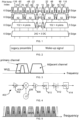
- Fig. 1 shows various ways for how the bandwidth in a 20 MHz channel may be divided among users.
- a user can here only be allocated to one resource unit (RU), but the size of the RU may be 26, 52, 106, or 242 sub-carriers.
- the options for sharing the channel between users are the same for both the DL and the UL.
- IEEE 802.11ax addresses the need for better multi-user support, it does not really address the need for very low power consumption, which may limit its usefulness for use cases when the transceiver would have to be powered by e.g. a coin cell battery.
- IEEE 802.11ba task group This amendment is developed by the IEEE 802.11ba task group (TG).
- IEEE 802.11 In IEEE 802.11 standards, like IEEE 802.11b, g, n, ac and ax, the channel access is to a large extent distributed among the stations (STAs), rather than scheduled by the AP, although IEEE 802.11ax goes towards being more scheduled in order to support multi-user transmission.
- the distributed channel access in IEEE 802.11 is based on carrier sense multiple access with collision avoidance (CSMA/CA).
- CSMA/CA is a listen before talk (LBT) scheme, where an STA which has a packet to send first senses the channel to determine whether the channel is idle or busy.
- LBT listen before talk
- the STA transmits the packet, whereas if the channel is determined to be busy, the transmission is deferred and a new attempt to transmit the packet is made at a later time.
- the receiver power threshold where the channel is determined to change from idle to busy will determine how aggressively an STA is trying to grab the channel, and is a very important design parameter for a system based on CSMA/CA. Essentially, if the threshold is set low so that the channel is determined to be busy already at a very low receiver power, say -82 dBm, then there is a risk that an STA defers from transmitting although a transmission would have been successful and without actually causing any problem for any other ongoing transmission.
- the problem with deferring from transmitting when actually not needed is commonly referred to as the "exposed node problem”.
- the threshold is set too high so that the channel is determined to be idle although there is an ongoing transmission, the generated interference may ruin the performance of the other link, and in addition the transmission itself may not be successful either. This is commonly referred to as a “hidden node problem”. Setting the threshold too high effectively means that a transmission from another node is not detected and thus this node will be hidden.
- the CSMA/CA and the determination of whether the channel is busy or idle is based a combination of preamble detect and energy detect.
- An STA that performs CSMA/CA will declare the channel as being busy if the preamble of an IEEE 802.11 packet is detected at a power of -82dBm or higher, or if any signal is detected at a power of -62dBm or higher. If neither of these conditions is met, the channel is declared as idle. So, an IEEE 802.11 STA is 20 dB "nicer" to another IEEE 802.11 STA using a certain preamble than it is to another kind of transmission.
- a WUS intended for a WUR would typically look very different than an ordinary IEEE 802.11 signal carrying data.
- the preamble discussed above being used for preamble detect and ensuring that other STAs will defer already at a received power level of -82dB is transmitted over a 20 MHz wide channel, with the actual bandwidth of the signal being roughly 16 MHz wide.
- the WUS can be expected to be considerably less, say only 4 MHz wide.
- other STAs would rely on energy detect to detect a WUS, thus only declaring the channel as being busy if the WUS is received at a power level of -62dBm or higher.
- CSMA/CA The idea with CSMA/CA is concerned with making sure that STAs using the same channel will not interfere with an ongoing transmission. For STAs using adjacent channels, it is expected that the filtering will ensure that these will not interfere, and therefore, effectively, a STA using an adjacent channel will not perform CSMA/CA for the primary channel, as illustrated in Fig. 3 .
- the received signal is amplified in a low noise amplifier (LNA) 402 and then down-converted from the radio frequency (e.g. around 2.4 GHz) to an intermediate frequency (IF) at, say, 10 MHz, by a mixer 404.
- the IF signal may then be further amplified by an IF amplifier 408 and filtered through a bandpass filter (BPF) 410 centred around IF.
- BPF bandpass filter
- the bandwidth of the BPF 410 is approximately equal to the bandwidth of the desired signal such that potentially interfering signals in adjacent channels are attenuated by the BPF 410.
- the frequency generated by the local-oscillator (LO) 406 is very accurate, because otherwise there is a risk that a non-negligible part of the energy of the WUS will be filtered out, which impacts negatively the performance of the WUR.
- the signal is demodulated using an envelope detector 412, converted to a digital stream by means of an analog-to-digital converter (ADC) 414, and then processed digitally.
- ADC analog-to-digital converter
- the digital processing involves e.g. time estimation by means of correlating the received signal with a known synchronization sequence.
- the architecture illustrated in Fig. 4 is largely operating in the analog domain, e.g. the envelope detector 412 is before the ADC 414, it is possible to instead perform a larger part of the receiver processing in the digital domain. E.g. additional filtering and the envelope detector 412 may be implemented in the digital domain.
- the present invention is applicable irrespective of whether the envelope detector is implemented in the analog or digital domain, and it does also not depend on implementation details related to exactly how the envelope detector is implemented. Instead, the invention is concerned with potential issues due to phase noise in the LO and the ability to filter out adjacent channel interference, as illustrated in Fig. 3 .
- the purposes of the BPF before the envelope detector is thus to filter out adjacent channels, but it may not have to filter out data transmitted concurrently with WUS using e.g. OFDMA, as illustrated in Fig. 5 .
- the reason why the BPF does not need to filter the data sent in the same channel as the WUS is that both the data and the WUS in this case are transmitted from the same transmitter, and then it is possible to control the relative strength of these signals and by that ensure that the envelope detector will work properly.
- ACI the situation is completely different since the ACI originates from another transmitter, and thus this is not under control and may also be significantly stronger than the signal to receive in the primary channel.
- the LO generation may consume a significant part of the total power of the WUR.
- the requirements of the LO are very relaxed, both concerning the accuracy of the centre frequency of the LO and its purity, i.e., the phase noise of the LO.
- the relaxed frequency accuracy of the LO is to some extent addressed by allowing a bandwidth of the BPF which is considerably larger than the BW of the WUS itself.
- the effect of phase noise is not, and is in fact worsened because of the relatively wide BPF.
- the frequency inaccuracy With respect to the frequency inaccuracy, suppose that the inaccuracy would be as much as half the channel bandwidth, so 10 MHz for a 20 MHz Wi-Fi channel. Then the bandwidth of the BPF would have to be 20 MHz + the bandwidth of the WUS to ensure that the WUS would actually be in the passband of the filter. However, if a filter that is more than 20 MHz wide is selected and in addition there is a 10 MHz frequency error, it is easy to see that an adjacent channel interferer will not be properly filtered out. Thus, if there in fact is an interfering signal of significant strength on an adjacent channel, one may need to ensure that the frequency accuracy is good enough so that a more narrow filter can be employed.
- P adj is the receiver power of the adjacent interference
- P PN is the power spectrum density of the phase noise (assumed flat over the bandwidth BW)
- BW is the bandwidth of the BPF before the envelope detector. All numbers are here in dB and dBm.
- the C/I at the input of the detector should be at least 0 dB. This means that the C/I at the input to the mixer must not be lower than -45 dB. If e.g. the desired signal, C, is received at -90 dBm, the interference in the adjacent channel must not be received at a power of -45dBm or more. Since a Wi-Fi transmitter typically would use at least 15dBm output power, this would correspond to a pathloss of 60dB or more in order for the WUR not to be interfered such that the performance would be significantly degraded.
- the WUR would consequently not work properly. It is of course possible to counteract this problem by making sure that the phase noise is on a sufficiently low level. Say that one would require that the WUR should be able to operate also when the interference power is at -25dBm (corresponding to a path loss of 40 dB, which in the 2.4 GHz ISM band roughly equals 1 meter distance from the interferer). One would then design the LO such that the integrated phase noise would not exceed -65dBc. The problem with this approach is that generating this LO signal would consume more power, and the only time this would actually be needed would be when the WUR is located at a distance to an interferer as close as 1 meter.
- the phase noise of the LO signal used for downconverting the received signal is adjusted by having two or more LO generation circuits available and select which one to use for down-conversion based on the requirement to handle ACI, such that an LO generation circuit requiring more power is used when it is determined that the requirements on handling ACI is high. For example, when the estimated ACI power exceeds a predetermined threshold a first LO generation circuit is chosen. Otherwise a second LO generation circuit is chosen. The first LO generation circuit has higher power consumption than the second LO generation circuit.
- the phase noise of the LO signal used for downconverting the received signal is adjusted, varying the power consumption of the LO generation circuit based on the requirement to handle ACI, presuming that the increase of power implies lower phase noise for the type of LO generation circuit used, such that more power is used when it is determined that the requirements on handling ACI is high. For example, when the estimated ACI power exceeds a predetermined threshold a first set of parameter values for the LO generation circuit is used. Otherwise a second set of parameter values for the LO generation circuit is used. The LO generation circuit has higher power consumption when the first set of values is used. Parameters could for example be some of a resistance, capacitance, inductance, current, etc. This is thus applicable when the LO generation circuit has adjustable phase noise characteristics.
- the main receiver is used to determine whether there is an interfering signal in an adjacent channel and, if so, estimate the received power. This may for instance be done by periodically tune the main receiver to the adjacent channels that may cause problems due to reciprocal mixing in case there is a strong interfering signal and measure e.g. signal strength.
- information about the interfering signal may also be acquired from an external node, e.g. an access point or base station of the communication network, by the main receiver.
- the WUR itself will determine whether there is an interfering signal in an adjacent channel and if so estimate the received power. This may for instance be done by periodically tune the WUR to the adjacent channels that may cause problem due to lack of filtering or reciprocal mixing in case there is a strong interfering signal. Whereas the WUR typically detects the presence of a WUS by correlation in the digital domain, the detection of strong adjacent interference would typically be performed by just estimating the received power in the analog domain. This is feasible as the power level of an interfering signal that potentially can cause harm will be, say, 30-40 dB stronger than the power of a WUS to be detected. For example, the presence and power of adjacent interference is detected by changing the frequency of the LO to measure on the channel of interest, or the presence and power of adjacent interference is detected by increasing the bandwidth of the BPF to detect whether there is any signal.
- the AP scans adjacent channels and indicates to the STA the ACI level. This can be done e.g. through a management frame. This can be useful in isolated environments (e.g. mines or shielded industrial environments) where the AP can determine whether adjacent channels are used at all. This saves energy at the STA since it needs not to scan adjacent channels.
- phase noise characteristics are adjusted for one LO generation circuit
- this may be combined with selecting another LO generation circuit, for example when enough adjustment is not feasible, or when adjustment of the one LO generation circuit emanates in worse performance to power relation than selecting another LO generation circuit.
- phase noise power level may be determined based on what C/I can be accepted at the input of the detector, which in turn may depend on exact details for how the WUR is implemented.
- the required C/I is based on what C/I is required for co-channel interference. Since the required C/I for co-channel interference easily can be determined e.g. by means of simulation this may be used as target also when the interference originates from an adjacent channel. In another example, the required C/I takes into account that the interference may be bursty, such that potential impact on reception is considered. That is, there is a possibility that the WUR is based on the assumption that the total interference is relatively constant throughout the reception of the entire packet e.g. because a decision threshold has to be set based on this. In this case, the WUR may be able to operate at relatively small C/I, say 0dB, but a relative small change of the interference may still cause a problem. If this is the case, the C/I is selected such that the receiver is able to operate if the interference conditions alters between the interference being absent to the interfering being present at a maximum allowed level.
- scanning for potential adjacent interference is done on a regular basis, say once every hour or once every day. This periodic scanning may be performed both when the WUR is using the relaxed LO, in which case the scanning essentially is to see if interference has appeared so that the more stringent LO settings are needed, or when the LO is using the more stringent setting, in which case the scanning is performed to see whether the interference has disappeared so that the more relaxed LO settings may be used instead.
- the scanning is performed upon need. Specifically, if the quality of the WUS is found to be poor or if no WUS has been received for a long time, the WUR may decide that a potential interferer at an adjacent channel may be present and may therefore decide to perform a scan. The WUR may in this case also skip the scan, and just change to the more accurate LO performance to monitor whether the performance improves.
- Fig. 6 is a flow chart schematically illustrating a method according to an embodiment.
- the method is applicable to a radio receiver comprising a local oscillator arrangement arranged to provide a frequency for down-conversion of radio frequency signal to an intermediate frequency or a baseband frequency in the radio receiver.
- the local oscillator arrangement is presumed to be capable of selectably providing multiple frequency generation qualities, where the respective frequency generation quality emanates in more or less power consumption, as discussed above.
- the method comprises estimating 600 a tolerable frequency generation quality for the current operation of the radio receiver or determining 600a whether the current operation of the radio receiver is satisfactory in sense of a currently provided frequency generation quality. The method thus enables selecting 601 a frequency generation quality for the local oscillator arrangement based on the estimation or determination.
- the selection 601 may include comparing the estimated 600 and/or determined 600a values with one or more thresholds wherein the tolerable frequency generation quality for example may be given from a look-up table based on which threshold is reached. Based on the selection, the method includes adjusting 602 the frequency generation quality of the local oscillator arrangement according to the selection.
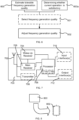
- Fig. 7 is a block diagram schematically illustrating a radio arrangement 700 according to an embodiment.
- the radio arrangement comprises an antenna arrangement 702, a wake-up receiver 704 and a main receiver 705 connected to the antenna arrangement 702, an optional transmitter 706 connected to the antenna arrangement 702, a processing element 708 which may comprise one or more circuits, one or more input interfaces 710 and one or more output interfaces 712.
- the interfaces 710, 712 can be user interfaces and/or signal interfaces, e.g. electrical or optical.
- the radio arrangement 700 may be arranged to operate in a communication network, e.g. a wireless local area network or a cellular communication network.
- the radio arrangement 700 is capable of keeping low power consumption and dealing with interferers as elucidated above.
- the processing element 708 here also functionally illustrates the controller of the wake-up radio.
- the processing element 708 can also fulfill a multitude of tasks, ranging from signal processing to enable reception and transmission since it is connected to the wake-up receiver 704, the main receiver 705 and the optional transmitter 706, and also be included in executing applications, controlling the interfaces 710, 712, etc.
- the processing element 708 comprises or is connected to a memory 714, and comprises one of more processing circuits 716.
- the methods according to the present invention is suitable for implementation with aid of processing means, such as computers and/or processors, especially for the case where the processing element 708 demonstrated above comprises a processor handling controlling of the radio resources, and the wake-up radio in particular. Therefore, there is provided computer programs, comprising instructions arranged to cause the processing means, processor, or computer to perform the steps of any of the methods according to any of the embodiments described with reference to Fig. 1 to 6 .
- the computer program preferably comprises program code which is stored on a computer readable medium 800, as illustrated in Fig.
- FIG. 8 which can be loaded and executed by a processing means, processor, or computer 802 to cause it to perform the methods, respectively, according to embodiments of the present invention, preferably as any of the embodiments described with reference to Figs 1 to 6 .
- the computer 802 and computer program product 800 can be arranged to execute the program code sequentially where actions of the any of the methods are performed stepwise.
- the processing means, processor, or computer 802 is preferably what normally is referred to as an embedded system.
- the depicted computer readable medium 800 and computer 802 in Fig. 8 should be construed to be for illustrative purposes only to provide understanding of the principle, and not to be construed as any direct illustration of the elements.
Landscapes
- Engineering & Computer Science (AREA)
- Computer Networks & Wireless Communication (AREA)
- Signal Processing (AREA)
- Power Engineering (AREA)
- Noise Elimination (AREA)
- Circuits Of Receivers In General (AREA)
- Mobile Radio Communication Systems (AREA)
Claims (10)
- Funkempfänger (400, 704), der so angeordnet ist, dass er als Aufweckfunkempfänger (704) für einen mit dem Funkempfänger (400, 704) interagierenden Hauptempfänger (705) betrieben wird, wobei der Funkempfänger (400, 704) eine lokale Oszillatoranordnung (406) und eine Steuereinheit (802) umfasst, wobeidie lokale Oszillatoranordnung (406) so angeordnet ist, dass sie ein Signal zur Abwärtswandlung eines Funkfrequenzsignals in eine Zwischenfrequenz oder eine Basisbandfrequenz in dem Funkempfänger (400, 704) bereitstellt, und die lokale Oszillatoranordnung (406) in der Lage ist, selektiv mehrere Frequenzerzeugungsqualitäten bereitzustellen, unddie Steuereinheit (802) so angeordnet ist, dass sie eine tolerierbare Frequenzerzeugungsqualität für den aktuellen Betrieb des Funkempfängers (400, 704) schätzt oder bestimmt, ob der aktuelle Betrieb des Funkempfängers (400, 704) im Sinne einer aktuell bereitgestellten Frequenzerzeugungsqualität zufriedenstellend ist, und auf der Grundlage der Schätzung oder Bestimmung die Frequenzerzeugungsqualität der lokalen Oszillatoranordnung (406) durch Auswahl einer der mehreren Frequenzerzeugungsqualitäten einstellt,wobei die Schätzung der tolerierbaren Frequenzerzeugungsqualität einen Empfang einer Anzeige vom Hauptempfänger (705) mit Informationen über ein Störsignal in einem benachbarten Funkkanal beinhaltet.
- Funkempfänger (400, 704) nach Anspruch 1, wobei die Schätzung beinhaltet, dass der Funkempfänger (400, 704) so angeordnet ist, dass er
den Hauptempfänger periodisch veranlasst, sich auf einen Nachbarkanal abzustimmen, der eine gegenseitige Vermischung verursachen kann, und dass er Informationen über Signale auf dem Nachbarkanal bereitstellt. - Funkempfänger (400, 704) nach Anspruch 2, wobei die periodische Abstimmung auf einen Nachbarkanal umfasst, dass der Hauptempfänger veranlasst wird, Nachbarkanäle nach Signalen abzutasten, die eine gegenseitige Vermischung verursachen können.
- Funkempfänger (400, 704) nach Anspruch 2, wobei die periodische Abstimmung auf einen Nachbarkanal umfasst, dass der Hauptempfänger veranlasst wird, eine große Bandbreite auf Signale zu prüfen, die eine gegenseitige Vermischung verursachen können, wobei die große Bandbreite die Nachbarkanäle abdeckt, die eine gegenseitige Vermischung verursachen können.
- Funkanordnung (700), die einen Aufweckempfänger (704) nach einem der Ansprüche 1 bis 4 und einen Hauptempfänger (705) beinhaltet, der so angeordnet ist, dass er mit dem Aufweckempfänger (704) interagiert.
- Verfahren eines Funkempfängers, der eine lokale Oszillatoranordnung umfasst, die so angeordnet ist, dass sie ein Signal zur Abwärtswandlung eines Funkfrequenzsignals in eine Zwischenfrequenz oder eine Basisbandfrequenz in dem Funkempfänger bereitstellt, und wobei die lokale Oszillatoranordnung in der Lage ist, selektiv mehrere Frequenzerzeugungsqualitäten bereitzustellen, wobei der Funkempfänger so angeordnet ist, dass er als ein Aufweckfunkempfänger für einen mit dem Funkempfänger interagierenden Hauptempfänger betrieben wird, wobei das Verfahren Folgendes umfasstSchätzen (600) einer tolerierbaren Frequenzerzeugungsqualität für den aktuellen Betrieb des Funkempfängers oder Bestimmen (600a), ob der aktuelle Betrieb des Funkempfängers im Sinne einer aktuell bereitgestellten Frequenzerzeugungsqualität zufriedenstellend ist, sodass eine Frequenzerzeugungsqualität für die lokale Oszillatoranordnung auf der Grundlage der Schätzung oder Bestimmung ausgewählt werden kann (601); undEinstellen (602) der Frequenzerzeugungsqualität der lokalen Oszillatoranordnung entsprechend der Auswahl,wobei das Schätzen (600) der tolerierbaren Frequenzerzeugungsqualität Empfangen einer Anzeige vom Hauptempfänger mit Informationen über ein Störsignal in einem benachbarten Funkkanal beinhaltet.
- Verfahren nach Anspruch 6, wobei das Schätzen (600)
das periodische Veranlassen des Hauptempfängers beinhaltet, sich auf einen Nachbarkanal abzustimmen, der eine gegenseitige Vermischung verursachen kann, und Informationen über Signale auf dem Nachbarkanal bereitzustellen. - Verfahren nach Anspruch 7, wobei die periodische Abstimmung auf einen Nachbarkanal umfasst, dass der Hauptempfänger veranlasst wird, Nachbarkanäle nach Signalen abzutasten, die eine gegenseitige Vermischung verursachen können.
- Verfahren nach Anspruch 8, wobei die periodische Abstimmung auf einen Nachbarkanal umfasst, dass der Hauptempfänger veranlasst wird, eine große Bandbreite auf Signale zu prüfen, die eine gegenseitige Vermischung verursachen können, wobei die große Bandbreite die Nachbarkanäle abdeckt, die eine gegenseitige Vermischung verursachen können.
- Computerprogramm, das Anweisungen umfasst, die, wenn sie auf einem Prozessor (802) einer Steuereinheit eines Funkempfängers (400, 704) ausgeführt werden, den Funkempfänger (400, 704) veranlassen, das Verfahren nach einem der Ansprüche 6 bis 9 durchzuführen.
Applications Claiming Priority (2)
| Application Number | Priority Date | Filing Date | Title |
|---|---|---|---|
| US201762470467P | 2017-03-13 | 2017-03-13 | |
| PCT/EP2017/067568 WO2018166638A1 (en) | 2017-03-13 | 2017-07-12 | Radio receiver, method and computer program |
Publications (2)
| Publication Number | Publication Date |
|---|---|
| EP3596832A1 EP3596832A1 (de) | 2020-01-22 |
| EP3596832B1 true EP3596832B1 (de) | 2024-09-04 |
Family
ID=59350921
Family Applications (1)
| Application Number | Title | Priority Date | Filing Date |
|---|---|---|---|
| EP17739962.3A Active EP3596832B1 (de) | 2017-03-13 | 2017-07-12 | Funkempfänger, verfahren und computerprogramm |
Country Status (7)
| Country | Link |
|---|---|
| US (2) | US10998928B2 (de) |
| EP (1) | EP3596832B1 (de) |
| JP (1) | JP6921970B2 (de) |
| KR (1) | KR102243344B1 (de) |
| CN (1) | CN110383701B (de) |
| AU (2) | AU2017404169A1 (de) |
| WO (1) | WO2018166638A1 (de) |
Families Citing this family (7)
| Publication number | Priority date | Publication date | Assignee | Title |
|---|---|---|---|---|
| FR3084489B1 (fr) * | 2018-07-26 | 2020-09-11 | Etat Francais Represente Par Le Delegue General Pour Larmement | Procede de detection d’au moins un equipement informatique compromis au sein d’un systeme d’information |
| KR102674478B1 (ko) * | 2019-12-02 | 2024-06-11 | 텔레폰악티에볼라겟엘엠에릭슨(펍) | 무선통신 시스템에서의 웨이크업 통신 |
| KR102796035B1 (ko) * | 2021-01-21 | 2025-04-16 | 하이테라 커뮤니케이션즈 코포레이션 리미티드 | 적응적 간섭 방지 방법 및 적응적 간섭 방지 장치 |
| WO2023029031A1 (en) * | 2021-09-06 | 2023-03-09 | Apple Inc. | New radio low power wakeup radio |
| US12308896B2 (en) * | 2021-10-15 | 2025-05-20 | Cypress Semiconductor Corporation | Systems, methods, and devices for channel interference detection in wireless devices |
| CN116707557B (zh) * | 2022-12-20 | 2024-05-03 | 荣耀终端有限公司 | 信道选择方法、接收机及存储介质 |
| US12538147B2 (en) | 2023-05-24 | 2026-01-27 | T-Mobile Usa, Inc. | Determining a root cause of a failed interaction between a mobile device and a wireless telecommunication network |
Family Cites Families (26)
| Publication number | Priority date | Publication date | Assignee | Title |
|---|---|---|---|---|
| US5193210A (en) | 1991-07-29 | 1993-03-09 | Abc Auto Alarms, Inc. | Low power RF receiver |
| US6337885B1 (en) | 1998-02-13 | 2002-01-08 | Telefonaktiebolaget Lm Ericsson (Publ) | Radio receiver that digitizes a received signal at a plurality of digitization frequencies |
| KR20000006905A (ko) | 1999-11-11 | 2000-02-07 | 이승엽 | 동적 필터링 특성을 가지는 주파수 변환장치 |
| US6906309B2 (en) * | 2001-11-15 | 2005-06-14 | Hrl Laboratories, Llc | Injection-seeding of a multi-tone photonic oscillator |
| US7120412B2 (en) * | 2002-05-31 | 2006-10-10 | Broadcom Corporation | Calibration circuit for VCO |
| US6999742B2 (en) * | 2002-07-26 | 2006-02-14 | Mitsubishi Electric Research Laboratories, Inc. | By-passing adjacent channel interference removal in receivers |
| DE10302647A1 (de) * | 2003-01-23 | 2004-08-19 | Fraunhofer-Gesellschaft zur Förderung der angewandten Forschung e.V. | Vorrichtung und Verfahren zum Abwärtsmischen eines Eingangssignals in ein Ausgangssignal |
| GB2401498B (en) * | 2003-05-07 | 2006-02-22 | Zarlink Semiconductor Ltd | Tuner |
| US7463872B2 (en) | 2005-02-24 | 2008-12-09 | Research In Motion Limited | Methods and apparatus for controlling a gain state of a wireless receiver operating in an idle mode |
| US7590432B2 (en) | 2005-10-06 | 2009-09-15 | Broadcom Corporation | Mobile communication device with low power receiver for signal detection |
| US20090081961A1 (en) * | 2007-09-24 | 2009-03-26 | Ahmadreza Rofougaran | Method and system for injection locking an oscillator via frequency multiplication of a multiphase signal |
| US7920839B2 (en) | 2008-02-04 | 2011-04-05 | Skyworks Solutions, Inc. | System and method for station detection and seek in a radio receiver |
| JP2010147622A (ja) | 2008-12-17 | 2010-07-01 | Toshiba Corp | 通信機、通信方法 |
| US8660498B2 (en) * | 2009-06-29 | 2014-02-25 | Motorola Solutions, Inc. | Method for database driven channel quality estimation in a cognitive radio network |
| US8514989B2 (en) * | 2009-08-24 | 2013-08-20 | Siano Mobile Silicon Ltd. | Method circuit and system for adapting a receiver receive chain based on detected background noise |
| CN102163982B (zh) * | 2011-01-24 | 2014-03-12 | 中国科学院半导体研究所 | 超低功耗ook接收装置 |
| KR101241742B1 (ko) | 2011-07-29 | 2013-03-11 | 주식회사 파이칩스 | 방해파 제거 기능을 갖는 웨이크 업 수신기 및 이를 포함하는 송수신기 |
| US8649755B2 (en) * | 2011-12-16 | 2014-02-11 | Qualcomm Incorporated | Timing circuit calibration in devices with selectable power modes |
| US20140009236A1 (en) * | 2012-07-03 | 2014-01-09 | Qualcomm Incorporated | Configurable multi-mode oscillators |
| GB2507087B (en) * | 2012-10-18 | 2015-07-22 | Broadcom Corp | Method and apparatus for signal reception |
| JP6261774B2 (ja) | 2014-05-27 | 2018-01-17 | コーニンクレッカ フィリップス エヌ ヴェKoninklijke Philips N.V. | 同期を伴う人体結合通信デバイス |
| CN104135296B (zh) * | 2014-07-12 | 2017-03-15 | 无锡中星微电子有限公司 | 可调中频无线接收机及蓝牙模块 |
| JP6772700B2 (ja) * | 2016-09-15 | 2020-10-21 | カシオ計算機株式会社 | 測位装置、電子時計、測位制御方法、及びプログラム |
| EP3577969B1 (de) * | 2017-01-31 | 2020-12-02 | Telefonaktiebolaget LM Ericsson (publ) | Verfahren und netzwerkknoten für planung |
| CN107749621B (zh) * | 2017-10-25 | 2020-08-11 | 东北电力大学 | 一种电力系统动态稳定协同辨识方法 |
| US11356966B2 (en) * | 2020-05-05 | 2022-06-07 | Kabushiki Kaisha Toshiba | Carrier frequency offset estimation and elimination |
-
2017
- 2017-07-12 EP EP17739962.3A patent/EP3596832B1/de active Active
- 2017-07-12 AU AU2017404169A patent/AU2017404169A1/en not_active Abandoned
- 2017-07-12 WO PCT/EP2017/067568 patent/WO2018166638A1/en not_active Ceased
- 2017-07-12 KR KR1020197026816A patent/KR102243344B1/ko active Active
- 2017-07-12 JP JP2019543988A patent/JP6921970B2/ja active Active
- 2017-07-12 US US16/488,390 patent/US10998928B2/en active Active
- 2017-07-12 CN CN201780088082.1A patent/CN110383701B/zh active Active
-
2021
- 2021-02-18 US US17/178,685 patent/US11394416B2/en active Active
- 2021-05-11 AU AU2021202978A patent/AU2021202978B2/en active Active
Also Published As
| Publication number | Publication date |
|---|---|
| US11394416B2 (en) | 2022-07-19 |
| US10998928B2 (en) | 2021-05-04 |
| JP2020511049A (ja) | 2020-04-09 |
| KR102243344B1 (ko) | 2021-04-22 |
| US20200235769A1 (en) | 2020-07-23 |
| US20210175918A1 (en) | 2021-06-10 |
| CN110383701B (zh) | 2021-11-05 |
| EP3596832A1 (de) | 2020-01-22 |
| WO2018166638A1 (en) | 2018-09-20 |
| KR20190116425A (ko) | 2019-10-14 |
| AU2021202978A1 (en) | 2021-06-03 |
| CN110383701A (zh) | 2019-10-25 |
| JP6921970B2 (ja) | 2021-08-18 |
| AU2017404169A1 (en) | 2019-08-29 |
| AU2021202978B2 (en) | 2023-04-20 |
Similar Documents
| Publication | Publication Date | Title |
|---|---|---|
| US11394416B2 (en) | Radio receiver, method and computer program | |
| US11304204B2 (en) | Method and apparatus for signal interference processing | |
| US9832785B2 (en) | Multi-radio coexistence | |
| US8576825B2 (en) | Method and system for sensing available spectrum in wireless communication systems | |
| US8655400B2 (en) | Reduced transmit power for wireless radio coexistence | |
| KR101517241B1 (ko) | 중계국 선택 방법 | |
| US20080025341A1 (en) | Method and system for granting of channel slots | |
| US8488568B2 (en) | Method and system of interferer signal detection | |
| US20140301339A1 (en) | Non-Contiguous Carrier Aggregation | |
| EP2900029B1 (de) | Gemeinsame wlan-leistungs- und -ratensteuerung zur verringerung von kolokalisierten lte tdd-interferenzen | |
| US12457632B2 (en) | Ue signal to interference power ratio detection for network scheduling assistance | |
| US20240015669A1 (en) | Duty cycle determination for radio frequency exposure evaluation | |
| US10849002B2 (en) | License assisted access measurement | |
| JP2011142401A (ja) | 無線機、無線通信システム、それに用いる装置、方法およびプログラム | |
| US20140051441A1 (en) | Complex Intermediate Frequency Based Receiver Architecture | |
| HK1218483A1 (zh) | 对不同的无线通信技术的干扰管理 |
Legal Events
| Date | Code | Title | Description |
|---|---|---|---|
| STAA | Information on the status of an ep patent application or granted ep patent |
Free format text: STATUS: UNKNOWN |
|
| STAA | Information on the status of an ep patent application or granted ep patent |
Free format text: STATUS: THE INTERNATIONAL PUBLICATION HAS BEEN MADE |
|
| PUAI | Public reference made under article 153(3) epc to a published international application that has entered the european phase |
Free format text: ORIGINAL CODE: 0009012 |
|
| STAA | Information on the status of an ep patent application or granted ep patent |
Free format text: STATUS: REQUEST FOR EXAMINATION WAS MADE |
|
| 17P | Request for examination filed |
Effective date: 20190917 |
|
| AK | Designated contracting states |
Kind code of ref document: A1 Designated state(s): AL AT BE BG CH CY CZ DE DK EE ES FI FR GB GR HR HU IE IS IT LI LT LU LV MC MK MT NL NO PL PT RO RS SE SI SK SM TR |
|
| AX | Request for extension of the european patent |
Extension state: BA ME |
|
| DAV | Request for validation of the european patent (deleted) | ||
| DAX | Request for extension of the european patent (deleted) | ||
| STAA | Information on the status of an ep patent application or granted ep patent |
Free format text: STATUS: EXAMINATION IS IN PROGRESS |
|
| 17Q | First examination report despatched |
Effective date: 20211123 |
|
| GRAP | Despatch of communication of intention to grant a patent |
Free format text: ORIGINAL CODE: EPIDOSNIGR1 |
|
| STAA | Information on the status of an ep patent application or granted ep patent |
Free format text: STATUS: GRANT OF PATENT IS INTENDED |
|
| INTG | Intention to grant announced |
Effective date: 20240404 |
|
| GRAS | Grant fee paid |
Free format text: ORIGINAL CODE: EPIDOSNIGR3 |
|
| GRAA | (expected) grant |
Free format text: ORIGINAL CODE: 0009210 |
|
| STAA | Information on the status of an ep patent application or granted ep patent |
Free format text: STATUS: THE PATENT HAS BEEN GRANTED |
|
| AK | Designated contracting states |
Kind code of ref document: B1 Designated state(s): AL AT BE BG CH CY CZ DE DK EE ES FI FR GB GR HR HU IE IS IT LI LT LU LV MC MK MT NL NO PL PT RO RS SE SI SK SM TR |
|
| REG | Reference to a national code |
Ref country code: GB Ref legal event code: FG4D |
|
| REG | Reference to a national code |
Ref country code: CH Ref legal event code: EP |
|
| REG | Reference to a national code |
Ref country code: IE Ref legal event code: FG4D |
|
| REG | Reference to a national code |
Ref country code: DE Ref legal event code: R096 Ref document number: 602017084629 Country of ref document: DE |
|
| REG | Reference to a national code |
Ref country code: LT Ref legal event code: MG9D |
|
| REG | Reference to a national code |
Ref country code: NL Ref legal event code: MP Effective date: 20240904 |
|
| PG25 | Lapsed in a contracting state [announced via postgrant information from national office to epo] |
Ref country code: NO Free format text: LAPSE BECAUSE OF FAILURE TO SUBMIT A TRANSLATION OF THE DESCRIPTION OR TO PAY THE FEE WITHIN THE PRESCRIBED TIME-LIMIT Effective date: 20241204 |
|
| PG25 | Lapsed in a contracting state [announced via postgrant information from national office to epo] |
Ref country code: GR Free format text: LAPSE BECAUSE OF FAILURE TO SUBMIT A TRANSLATION OF THE DESCRIPTION OR TO PAY THE FEE WITHIN THE PRESCRIBED TIME-LIMIT Effective date: 20241205 Ref country code: FI Free format text: LAPSE BECAUSE OF FAILURE TO SUBMIT A TRANSLATION OF THE DESCRIPTION OR TO PAY THE FEE WITHIN THE PRESCRIBED TIME-LIMIT Effective date: 20240904 Ref country code: PL Free format text: LAPSE BECAUSE OF FAILURE TO SUBMIT A TRANSLATION OF THE DESCRIPTION OR TO PAY THE FEE WITHIN THE PRESCRIBED TIME-LIMIT Effective date: 20240904 |
|
| PG25 | Lapsed in a contracting state [announced via postgrant information from national office to epo] |
Ref country code: BG Free format text: LAPSE BECAUSE OF FAILURE TO SUBMIT A TRANSLATION OF THE DESCRIPTION OR TO PAY THE FEE WITHIN THE PRESCRIBED TIME-LIMIT Effective date: 20240904 |
|
| PG25 | Lapsed in a contracting state [announced via postgrant information from national office to epo] |
Ref country code: LV Free format text: LAPSE BECAUSE OF FAILURE TO SUBMIT A TRANSLATION OF THE DESCRIPTION OR TO PAY THE FEE WITHIN THE PRESCRIBED TIME-LIMIT Effective date: 20240904 |
|
| PG25 | Lapsed in a contracting state [announced via postgrant information from national office to epo] |
Ref country code: HR Free format text: LAPSE BECAUSE OF FAILURE TO SUBMIT A TRANSLATION OF THE DESCRIPTION OR TO PAY THE FEE WITHIN THE PRESCRIBED TIME-LIMIT Effective date: 20240904 |
|
| PG25 | Lapsed in a contracting state [announced via postgrant information from national office to epo] |
Ref country code: ES Free format text: LAPSE BECAUSE OF FAILURE TO SUBMIT A TRANSLATION OF THE DESCRIPTION OR TO PAY THE FEE WITHIN THE PRESCRIBED TIME-LIMIT Effective date: 20240904 Ref country code: RS Free format text: LAPSE BECAUSE OF FAILURE TO SUBMIT A TRANSLATION OF THE DESCRIPTION OR TO PAY THE FEE WITHIN THE PRESCRIBED TIME-LIMIT Effective date: 20241204 |
|
| PG25 | Lapsed in a contracting state [announced via postgrant information from national office to epo] |
Ref country code: RS Free format text: LAPSE BECAUSE OF FAILURE TO SUBMIT A TRANSLATION OF THE DESCRIPTION OR TO PAY THE FEE WITHIN THE PRESCRIBED TIME-LIMIT Effective date: 20241204 Ref country code: PL Free format text: LAPSE BECAUSE OF FAILURE TO SUBMIT A TRANSLATION OF THE DESCRIPTION OR TO PAY THE FEE WITHIN THE PRESCRIBED TIME-LIMIT Effective date: 20240904 Ref country code: NO Free format text: LAPSE BECAUSE OF FAILURE TO SUBMIT A TRANSLATION OF THE DESCRIPTION OR TO PAY THE FEE WITHIN THE PRESCRIBED TIME-LIMIT Effective date: 20241204 Ref country code: LV Free format text: LAPSE BECAUSE OF FAILURE TO SUBMIT A TRANSLATION OF THE DESCRIPTION OR TO PAY THE FEE WITHIN THE PRESCRIBED TIME-LIMIT Effective date: 20240904 Ref country code: HR Free format text: LAPSE BECAUSE OF FAILURE TO SUBMIT A TRANSLATION OF THE DESCRIPTION OR TO PAY THE FEE WITHIN THE PRESCRIBED TIME-LIMIT Effective date: 20240904 Ref country code: GR Free format text: LAPSE BECAUSE OF FAILURE TO SUBMIT A TRANSLATION OF THE DESCRIPTION OR TO PAY THE FEE WITHIN THE PRESCRIBED TIME-LIMIT Effective date: 20241205 Ref country code: FI Free format text: LAPSE BECAUSE OF FAILURE TO SUBMIT A TRANSLATION OF THE DESCRIPTION OR TO PAY THE FEE WITHIN THE PRESCRIBED TIME-LIMIT Effective date: 20240904 Ref country code: ES Free format text: LAPSE BECAUSE OF FAILURE TO SUBMIT A TRANSLATION OF THE DESCRIPTION OR TO PAY THE FEE WITHIN THE PRESCRIBED TIME-LIMIT Effective date: 20240904 Ref country code: BG Free format text: LAPSE BECAUSE OF FAILURE TO SUBMIT A TRANSLATION OF THE DESCRIPTION OR TO PAY THE FEE WITHIN THE PRESCRIBED TIME-LIMIT Effective date: 20240904 |
|
| REG | Reference to a national code |
Ref country code: AT Ref legal event code: MK05 Ref document number: 1721473 Country of ref document: AT Kind code of ref document: T Effective date: 20240904 |
|
| PG25 | Lapsed in a contracting state [announced via postgrant information from national office to epo] |
Ref country code: NL Free format text: LAPSE BECAUSE OF FAILURE TO SUBMIT A TRANSLATION OF THE DESCRIPTION OR TO PAY THE FEE WITHIN THE PRESCRIBED TIME-LIMIT Effective date: 20240904 |
|
| PG25 | Lapsed in a contracting state [announced via postgrant information from national office to epo] |
Ref country code: IS Free format text: LAPSE BECAUSE OF FAILURE TO SUBMIT A TRANSLATION OF THE DESCRIPTION OR TO PAY THE FEE WITHIN THE PRESCRIBED TIME-LIMIT Effective date: 20250104 Ref country code: PT Free format text: LAPSE BECAUSE OF FAILURE TO SUBMIT A TRANSLATION OF THE DESCRIPTION OR TO PAY THE FEE WITHIN THE PRESCRIBED TIME-LIMIT Effective date: 20250106 |
|
| PG25 | Lapsed in a contracting state [announced via postgrant information from national office to epo] |
Ref country code: SM Free format text: LAPSE BECAUSE OF FAILURE TO SUBMIT A TRANSLATION OF THE DESCRIPTION OR TO PAY THE FEE WITHIN THE PRESCRIBED TIME-LIMIT Effective date: 20240904 Ref country code: RO Free format text: LAPSE BECAUSE OF FAILURE TO SUBMIT A TRANSLATION OF THE DESCRIPTION OR TO PAY THE FEE WITHIN THE PRESCRIBED TIME-LIMIT Effective date: 20240904 |
|
| PG25 | Lapsed in a contracting state [announced via postgrant information from national office to epo] |
Ref country code: EE Free format text: LAPSE BECAUSE OF FAILURE TO SUBMIT A TRANSLATION OF THE DESCRIPTION OR TO PAY THE FEE WITHIN THE PRESCRIBED TIME-LIMIT Effective date: 20240904 Ref country code: AT Free format text: LAPSE BECAUSE OF FAILURE TO SUBMIT A TRANSLATION OF THE DESCRIPTION OR TO PAY THE FEE WITHIN THE PRESCRIBED TIME-LIMIT Effective date: 20240904 |
|
| PG25 | Lapsed in a contracting state [announced via postgrant information from national office to epo] |
Ref country code: CZ Free format text: LAPSE BECAUSE OF FAILURE TO SUBMIT A TRANSLATION OF THE DESCRIPTION OR TO PAY THE FEE WITHIN THE PRESCRIBED TIME-LIMIT Effective date: 20240904 |
|
| PG25 | Lapsed in a contracting state [announced via postgrant information from national office to epo] |
Ref country code: IT Free format text: LAPSE BECAUSE OF FAILURE TO SUBMIT A TRANSLATION OF THE DESCRIPTION OR TO PAY THE FEE WITHIN THE PRESCRIBED TIME-LIMIT Effective date: 20240904 Ref country code: SK Free format text: LAPSE BECAUSE OF FAILURE TO SUBMIT A TRANSLATION OF THE DESCRIPTION OR TO PAY THE FEE WITHIN THE PRESCRIBED TIME-LIMIT Effective date: 20240904 |
|
| REG | Reference to a national code |
Ref country code: DE Ref legal event code: R097 Ref document number: 602017084629 Country of ref document: DE |
|
| PG25 | Lapsed in a contracting state [announced via postgrant information from national office to epo] |
Ref country code: DK Free format text: LAPSE BECAUSE OF FAILURE TO SUBMIT A TRANSLATION OF THE DESCRIPTION OR TO PAY THE FEE WITHIN THE PRESCRIBED TIME-LIMIT Effective date: 20240904 |
|
| PLBE | No opposition filed within time limit |
Free format text: ORIGINAL CODE: 0009261 |
|
| STAA | Information on the status of an ep patent application or granted ep patent |
Free format text: STATUS: NO OPPOSITION FILED WITHIN TIME LIMIT |
|
| 26N | No opposition filed |
Effective date: 20250605 |
|
| PG25 | Lapsed in a contracting state [announced via postgrant information from national office to epo] |
Ref country code: SE Free format text: LAPSE BECAUSE OF FAILURE TO SUBMIT A TRANSLATION OF THE DESCRIPTION OR TO PAY THE FEE WITHIN THE PRESCRIBED TIME-LIMIT Effective date: 20240904 |
|
| PGFP | Annual fee paid to national office [announced via postgrant information from national office to epo] |
Ref country code: DE Payment date: 20250729 Year of fee payment: 9 |
|
| PGFP | Annual fee paid to national office [announced via postgrant information from national office to epo] |
Ref country code: GB Payment date: 20250728 Year of fee payment: 9 |