EP3596296B1 - Autonomous anti-mosquito net system for a fixed lower guide - Google Patents
Autonomous anti-mosquito net system for a fixed lower guide Download PDFInfo
- Publication number
- EP3596296B1 EP3596296B1 EP18808475.0A EP18808475A EP3596296B1 EP 3596296 B1 EP3596296 B1 EP 3596296B1 EP 18808475 A EP18808475 A EP 18808475A EP 3596296 B1 EP3596296 B1 EP 3596296B1
- Authority
- EP
- European Patent Office
- Prior art keywords
- ropes
- guide
- net
- fixed
- detachable
- Prior art date
- Legal status (The legal status is an assumption and is not a legal conclusion. Google has not performed a legal analysis and makes no representation as to the accuracy of the status listed.)
- Active
Links
Images





Classifications
-
- E—FIXED CONSTRUCTIONS
- E06—DOORS, WINDOWS, SHUTTERS, OR ROLLER BLINDS IN GENERAL; LADDERS
- E06B—FIXED OR MOVABLE CLOSURES FOR OPENINGS IN BUILDINGS, VEHICLES, FENCES OR LIKE ENCLOSURES IN GENERAL, e.g. DOORS, WINDOWS, BLINDS, GATES
- E06B9/00—Screening or protective devices for wall or similar openings, with or without operating or securing mechanisms; Closures of similar construction
- E06B9/52—Devices affording protection against insects, e.g. fly screens; Mesh windows for other purposes
- E06B9/522—Dimensionally adjustable fly screens
-
- E—FIXED CONSTRUCTIONS
- E06—DOORS, WINDOWS, SHUTTERS, OR ROLLER BLINDS IN GENERAL; LADDERS
- E06B—FIXED OR MOVABLE CLOSURES FOR OPENINGS IN BUILDINGS, VEHICLES, FENCES OR LIKE ENCLOSURES IN GENERAL, e.g. DOORS, WINDOWS, BLINDS, GATES
- E06B9/00—Screening or protective devices for wall or similar openings, with or without operating or securing mechanisms; Closures of similar construction
- E06B9/56—Operating, guiding or securing devices or arrangements for roll-type closures; Spring drums; Tape drums; Counterweighting arrangements therefor
- E06B9/58—Guiding devices
-
- E—FIXED CONSTRUCTIONS
- E06—DOORS, WINDOWS, SHUTTERS, OR ROLLER BLINDS IN GENERAL; LADDERS
- E06B—FIXED OR MOVABLE CLOSURES FOR OPENINGS IN BUILDINGS, VEHICLES, FENCES OR LIKE ENCLOSURES IN GENERAL, e.g. DOORS, WINDOWS, BLINDS, GATES
- E06B9/00—Screening or protective devices for wall or similar openings, with or without operating or securing mechanisms; Closures of similar construction
- E06B9/52—Devices affording protection against insects, e.g. fly screens; Mesh windows for other purposes
- E06B9/54—Roller fly screens
- E06B2009/543—Horizontally moving screens
-
- E—FIXED CONSTRUCTIONS
- E06—DOORS, WINDOWS, SHUTTERS, OR ROLLER BLINDS IN GENERAL; LADDERS
- E06B—FIXED OR MOVABLE CLOSURES FOR OPENINGS IN BUILDINGS, VEHICLES, FENCES OR LIKE ENCLOSURES IN GENERAL, e.g. DOORS, WINDOWS, BLINDS, GATES
- E06B9/00—Screening or protective devices for wall or similar openings, with or without operating or securing mechanisms; Closures of similar construction
- E06B9/56—Operating, guiding or securing devices or arrangements for roll-type closures; Spring drums; Tape drums; Counterweighting arrangements therefor
- E06B9/58—Guiding devices
- E06B2009/583—Cords or cables
Definitions
- the invention belongs to the field of mechanics of anti-mosquito net systems that are used for horizontal door sliding.
- anti-mosquito net screen
- the present invention concerns anti-mosquito systems with such pleated net (with pleats).
- these systems resemble a frame, which has two vertical sides, two cases: the retention case and the sliding case.
- the retention case is fixed, fastened and firmly attached to the one vertical side of the frame of the opening.
- a fixed side guide is fastened and firmly attached to the opposite vertical side of the frame of the opening.
- the sliding case is movable, it moves with a direction from the retention case towards the fixed side guide and vice versa, and at a position always parallel to those two parts.
- the pleated net is folded in pleats (frill), between the two vertical cases, the fixed retention case and the movable sliding case.
- the frame has on the top part a straight horizontal permanent guide and on the bottom part has either a second straight horizontal permanent guide, or an articulated guide.
- the present invention refers to systems using at their bottom part a straight permanent guide, not an articulated guide.
- the folding and unfolding of the pleated net is mainly done with the help of the ropes running the cloth, which start from one vertical case (in some systems) or both vertical cases facing each other, divided into groups (in some other systems), and crossing the lower guide of the system, whereas their ends are tied to the vertical fixed side guide at the top and bottom of the system. As the sliding case moves, the ropes unfold or fold with its movement, thereby helping the pleated net to fold and unfold.
- Another technical problem of the current state of the art is that had the dimensions of height of the retention case, the sliding case and the vertical side guide not been measured correctly, the entire anti-mosquito system is useless, the dimensions have to be measured again and a new system to be ordered again. That happens because during its placement the system is a single technical element, a ready-made frame of four sides, which was made according to the specific dimensions of the order and is fastened at the particular opening for which it has been ordered.
- the anti-mosquito system that has been cut and assembled according to wrong dimensions, especially the height of the vertical side guide and the two cases cannot be fixed, nor is there a possibility to substitute any of its components.
- the above technical problems aim to solve EP 0549209 , EP 1903175 and EP 0999335 , but without providing the possibility of correcting wrong dimensions.
- EP 1653038 aims also at solving the aforementioned technical problems; in EP 1653038 , however, as opposed to the current invention, the two horizontal guides of the system, the top and the bottom ones, do not have any independence. Neither the top guide nor the two end parts can be detached from the retention and the sliding cases without the dismantling of the whole system. If they are detached, the two retention ropes will be detached and then the bottom guide will be disassembled, as well as the bottom ends that are restrained by the bottom rope of retention and therefore the whole system.
- EP2034123 A1 A solution to the above technical problems is also recommended by EP2034123 A1 , where however, the use of additional technical means is presented as a technical difference with the current invention.
- Such means are the components with pulley which are screwed on the net on both its sides in order to direct the ropes ( fig. 1 , 3 ), while the present invention does not have components with pulleys on the net.
- end components are utilized where all the ropes end up on both of their end points ( fig. 5 ), and finally in EP2034123 an independent net system is presented which require two articulated guides, at the top and the bottom, in order to function properly, whereas on the contrary, the current invention at the top has a fixed horizontal top guide and at the bottom has a fixed guide.
- This invention of the autonomous two-sided opening system resolves the problem of getting wrong dimensions, as it is in the form of a kit. It also solves the above-mentioned technical problem where the width of the opening must necessarily be less than its height, as it does not use a rope end component. Thus, the movement of the pleats is unobstructed and consequently it does not require an opening only from one side, having the other side fixed on the frame.
- the invention has ropes which start above the net and on the same side, the side fixed at the retention case, and which run along the net parallel to each other, until the edge of the net, where there are metal trucks to fasten the ropes. Then the ropes pass through the trucks and are all directed to the upper fixed horizontal guide through a pulley located at the upper part of the sliding guide - in contrary to WO 2015/079267 , this system uses only 2 pulleys at the upper part of the sliding guide - and fastened to the top part of the vertical fixed side guide (top end).
- a wire rope has one end at the upper truck, passes horizontally over the net, then through a pulley at the upper part of the sliding guide, continues vertically to a second pulley at the bottom of the sliding guide, crosses the lower horizontal guide and is fastened to the lower part of the vertical fixed side guide (lower end).
- the wire rope which is guided to the lower horizontal guide through the sliding guide, it is exactly the opposite direction and its way from the ropes the ropes, which are also directed towards the upper horizontal guide through the sliding guide. All the ropes are fastened to the upper part of the system, whereas all the wire ropes have one end fastened to the top part of the system and the other end to the lower part of the system. This contrasting tension on the system brings the maximum stability.
- the system does not use a vertical fixed side guide, as one leaf stops opposite to the other.
- a run component and tension adjusters are used at the upper guide and a central end component is used at the lower guide.
- kits with case and driver height from 1900 to 2200 mm
- kit with height from 2201 to 2500 mm and “kit with height from 2501 to 2800 mm”.
- installation is easy and quick, as time is saved with the purchase of an autonomous kit.
- the installation of the kit itself on the spot is extremely fast and simple as it requires only cutting the system to the correct length and screwing the detachable caps. This makes the system extremely user-friendly.
- this invention uses self-detachable end components that are screwed into the system upon installation.
- an additional advantage is the drastic reduction of production costs, which in turn helps the consumers to save money.
- Another advantage of this invention is the single wire rope which gives stability throughout the system.
- a further advantage is that, unlike WO 2015/079267 , this invention presents autonomous systems having leaves that each one open from both sides. Thus, many autonomous leaves with such opening can be placed in series, offering great stability. This solves the technical problem of covering openings with a width larger than the height of the opening, as there is no limitation on the movement of each leaf and the total number of leaves.
- Drawing 1 illustrates the autonomous anti-mosquito system with a one-side opening, at which all ropes end and are fastened at the upper part of the vertical fixed side guide, whereas the wire rope ends and is fastened at the lower part of the same guide. The net is completely unfolded.
- Drawing 2 illustrates the autonomous anti-mosquito system, with the one-sided opening of drawing 1, as a double-leaved system closing centrally.
- the two systems are placed in the same frame opposite to each other with two sliding cases for the central closing/opening.
- the net of both leaves is unfolded by half.
- Drawing 3 illustrates a combination of drawings 1 and 2, the autonomous anti-mosquito system as a one-leaf system opening from both sides, two fixed side guides and two sliding cases. The net is unfolded by half on both sides.
- Drawing 4 illustrates a combination of drawings 1, 2 and 3, the autonomous anti-mosquito system, a double-leaved central system opening from both sides, two fixed side guides and four sliding cases. The net is unfolded by half at both leaves and both sides. In the center of the opening, above and down, there are run / end components, screwed onto the upper and lower horizontal guide.
- Drawing 5 illustrates the system of drawing 4, as a three-leaved central system opening from both sides, two fixed side guides and six sliding cases. The net is unfolded by half at three leaves and both sides. At the spots where the sliding cases meet, there are run / end components, screwed onto the upper and lower horizontal guide.
- Drawings 6-10 illustrate the run and end components of the ropes of the upper guide, that is, a central run component and two tension adjusters, which are screwed onto the upper horizontal guide.
- the perspective drawing 6 illustrates the central run component, in upper, lateral and lower side of profile.
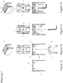
- Drawing 7 illustrates the four stages of screwing and fastening the central run component at the upper horizontal guide and the section of the profile of the upper horizontal guide in which the component is fixed ( fig. 7a, 7b, 7c, 7d ).
- the perspective drawing 8 illustrates the tension adjuster for the ropes in upper, lateral and lower side of profile.
- Drawing 9 illustrates the four stages of screwing and fastening the tension adjuster at the upper horizontal guide and the section of the profile of the upper horizontal guide in which the adjuster is fixed ( fig. 9a, 9b, 9c, 9d ).
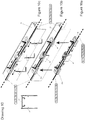
- Drawing 10 illustrates the central run component and two tension adjusters, the mode of run and fastening of ropes and the installation and fastening of the components in the upper horizontal guide, in three stages ( Fig. 10a, 10b, 10c ).
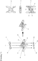
- Drawings 11 , 12 , 13 illustrate the lower ropes end component screwed in the center of the lower horizontal guide.
- Drawing 11 illustrates the lower component and the screws of the ropes end component the upper, lateral and lower side of the perspective profile.
- Drawing 12 illustrates the mode by which the lower end component enters and is fastened in the lower horizontal guide.
- Drawing 13 illustrates the mode by which the wire ropes are stretched and fastened on the lower end component in the lower horizontal guide, as well as the cap placement on it.
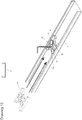
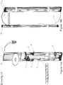
- Drawing 14 illustrates the autonomous anti-mosquito system with the one-sided opening of drawing 1, semi-assembled in a kit ( fig. 14a ) and the mode of assembling ( fig. 14b ).
- the autonomous anti-mosquito system has on the left and on the right two cases, the sliding case (1) and the retention case (2), in a vertical position, parallel to each other.
- the net is folded and the sliding case (1) is next to the retention case (2).
- the sliding case (1) begins moving towards the side fixed guide (24) the pleated net (7) unfolds and the opening closes, whereas when it moves to the opposite direction towards the retention guide (2), the pleated net (7) folds and the opening opens.
- the net (7) is run horizontally by six retention ropes (1a, 2a, 3a, 4a, 5a, 6a) all placed in a horizontal position and equally spaced apart from one another.
- All the ropes have trucks (21) as common starting points, which are located at that side of the net (7) which are found within the retention case (2).
- the ropes run across the net (7) horizontally, they reach the trucks (20) at the opposite side of the net (7) which are found within the sliding case (1), they run through the trucks (20) and are all directed upwards, to a detachable top edge (22) of the sliding case (1) within which there are two pulleys, the first (23) above the second (28) or vice-versa.
- the six retention ropes (1a, 2a, 3a, 4a, 5a, 6a) as a bundle run around the above pulley (23), then cross horizontally the upper fixed horizontal guide (25) towards the vertical fixed side guide (24), which has a detachable top edge (38) with an opening.
- the six retention ropes (1a, 2a, 3a, 4a, 5a, 6a) pass through the opening of the upper detachable edge (38) of the vertical fixed side guide (24), continue downwards as a bundle and are fixed on an adjuster (27) at the upper part of the vertical fixed side guide (24).
- one edge of the wire rope (43) is fastened to the same truck.
- the upwardly extending wire rope passes through an opening of the upper part of the detachable upper end (42) of the retention guide (2), the opening being at a height above the height of the net (7) and then crosses the upper fixed horizontal guide (25) in a position horizontally over the net, having the same direction with the unfolding direction of the net, then passes through the second pulley (28) inside the removable upper end (22) of the sliding case (1) at a height above the height of the net (7) without touching it, continues vertically towards the lower fixed horizontal guide (17), passes around the pulley (31) in the detachable lower edge (32) of the sliding case (1); then it is directed through the horizontal guide (17) towards the detachable lower end (35) with the opening of the fixed vertical side guide (24), passes through the opening of the end (35), continues upwards and is fixed to an adjuster (29) in the lower part of the vertical fixed side guide (24).
- the wire rope may have one edge fastened to the upper detachable edge (42) of the retention guide (2), runs horizontally the upper fixed horizontal guide and continues in exactly the same way, as described in detail in the previous paragraph.
- Drawing 2 illustrates the application of the autonomous anti-mosquito system with the one-sided opening of drawing 1, on a double leaved system with central closing.
- both systems are fixed on the same frame, opposite to each other and move, with their moving side, towards each other.
- Each system has on retention case (2, 50) by which it is fastened on the frame and one sliding case (1, 41) the moves and folds / unfolds the net.
- the leaves move towards each other, the anti-mosquito nets (7, 7a) are unfolded; the two sliding cases (1, 41) meet at the center of the opening and the double leaved central system closes.
- the function of the double leaved central system is the same with that of the one-sided opening system described above and illustrated in Drawing 1 , incorporating the same invention idea, changing only the component in which the ropes and the wire rope end, as the two-leaf central system does not have a vertical side guide at which the ropes and the wire rope stop, therefore they stop when the two sliding cases (1, 41) meet at the center of the opening.
- the nets (7, 7a) again each one are run horizontally by six retention ropes (1a, 2a, 3a, 4a, 5a, 6a and 1b, 2b, 3b, 4b, 5b, 6b) all placed horizontally and in equally spaced one from another, with common starting point the trucks (21, 21a) at the side of the net (7, 7a) which is fixed in the retention case (2, 50).
- the two rope bundles (1a, 2a, 3a, 4a, 5a, 6a and 1b, 2b, 3b, 4b, 5b, 6b) run around the upper (23, 23a) pulley of each leaf, cross horizontally the upper fixed horizontal guide (25) and reach the center of the opening at a ropes' central run component (47), exactly as the one-side opening described above and illustrated in drawing 1.
- the ropes'central run component (47) is fastened on the upper fixed horizontal guide (25) inside a socket (57) (drawings 6, 8, and 10).
- the run component (47) (drawing 6) has two through openings (48, 48a).
- the ropes (1a, 2a, 3a, 4a, 5a, 6a) of the first leaf come from the one side of the run component (47) and as a bundle pass through the opening (48), from downwards to upwards ( fig. 10a ), invert their movement and continue, inside the upper fixed guide (25) towards the retention case (2) from where they started and end to the tension adjuster (49) (drawing 8), also fixed on the upper fixed horizontal guide (25), inside the socket (57) in the same line with the ropes' central run component (47).
- the ropes (1b, 2b, 3b, 4b, 5b, 6b) of the second leaf come from the other side of the run component (47) and pass as a bundle from the other opening (48a), from downwards to upwards, invert their movement and continue inside the upper fixed guide (25) towards the retention case (50) from where they stared and end at the tension adjuster (49a) also fastened on the upper fixed horizontal guide (25) inside the socket (57) in the same line with the ropes' central run component (47).
- each wire rope (43, 43a) is fastened at the two first upper trucks (21, 21a), where the upper ropes are fastened (6a, 6b) (drawing 2).
- the wire rope (43) begins from the truck (21) of the first net (7) upwards, passes through the opening of the upper part of the detachable upper end (42) of the retention guide (2), the opening is above the net (7), then it crosses the upper fixed horizontal guide (25) horizontally above the net (7) without touching it, having the same direction with that of the net unfolding, it passes through the second pulley (28) inside the detachable upper edge (22) of the sliding case (1) and above the net (7), continues vertically towards the lower fixed horizontal guide (17), goes around the pulley (31) inside the detachable lower edge (32) of the sliding case (1).
- the wire rope (43a) of the other leaf starts from the truck (21a) of the second net (7a) upwards, passes from the opening of the upper part of the detachable upper part (42a) of the retention guide (50), the opening is above the net (7a), crosses the upper fixed horizontal guide (25) horizontally above the net (7a) without touching it, having the same direction with that of the net folding, then passes through the second pulley (28a) inside the detachable upper edge (22a) of the sliding case (41) and above the net (7a), continues vertically towards the lower fixed horizontal guide (17), passes around the pulley (31a) inside the detachable lower edge (32a) of the sliding case (41).
- the lower end component (51) consists of a plastic H-shaped component (26) and a plastic protective cap (56).
- the H-shaped plastic component (26) has a central fastening hole (36), two tension holes (52) of the wire ropes and two holes (54) through which the wire ropes pass.
- the plastic component (26) is pulled inside the socket of the lower horizontal guide (17) and is fastened in the center of the guide (17) with a screw (53) and a nut (53 a) from the central fastening hole (36).
- the two wire ropes (43, 43a) enter upwards from both holes (54) and are fastened with screws (55) and nuts (55a) at the two tension holes (52).
- the ropes' lower end component (51) has rails for the sliding cases that enter and are fastened inside it. The system is ready to be used.
- the system can function in exactly the same way as a one-leave system with a two-sided opening, without requiring a retention guide, with only two fixed side guides (24, 24a) and two sliding cases (1, 41).
- a set of ropes (1a, 2a, 3a, 4a, 5a, 6a) and two wire ropes (43, 43a) are used.
- all the ropes (1a, 2a, 3a, 4a, 5a, 6a) have a common starting point for the adjustor (27a) at the upper part of the vertical fixed side guide (24a).
- the six retention ropes (1a, 2a, 3a, 4a, 5a, 6a) pass around the upper pulley (23), run horizontally the upper fixed horizontal guide (25), toward the vertical fixed side (24), pass through the opening of the upper detachable end (38) of the vertical fixed side guide (24), go downwards and are fastened to an adjuster (27) inside the upper part of the vertical fixed side guide (24).
- Two wire ropes are used at the one-leaf system with two-sided opening.
- the two wire ropes (43, 43a) are fitted opposite, that is, one (43) starts from the upper part of the right fixed side guide (24a) and ends at the lower part (29) of the left fixed side guide (24) and the other one (43a) just opposite, that is, it starts from the upper part of the left fixed side guide (24) and ends at the lower part (29a) of the right fixed side guide (24a), whereas both pass above the net.
- one wire rope (43) is fastened with one edge at the upper part of the right vertical fixed side guide (24a).
- the wire rope passes upwards through the opening of the side guide (24a), which is above the net (7), and then with exactly the same way as in the system described above with reference to Drawing 1 , is crosses the upper fixed horizontal guide (25) horizontally, always above the net (7) without coming into contact with it, with a direction the same with that of the direction of unfolding the net, it passes the net (7), then passes through the second pulley (28) inside the detachable upper edge (22) of the left sliding case (1), continues downwards to the lower fixed horizontal guide (17), continues around the pulley (31) inside the detachable lower end (32) of the sliding case (1).
- the second wire rope (43a) follows a reverse course, is fastened with one edge at the upper part of the left vertical fixed side guide (24).
- the wire rope passes upwards through the opening of the side guide (24) which is above the net (7), and then in exactly the same way, as the system described above with reference to Drawing 1 , follows the reverse course of the first wire rope (43), that is, crosses the upper fixed horizontal guide (25) horizontally always above the height of the net without coming into contact with it, having the same direction with that of the unfolding of the net, passes by the net (7), then passes through the second pulley (28a) inside the detachable upper edge (22a) of the right sliding case (41), continues vertically downwards to the fixed horizontal guide (17), continues round the pulley (31a) inside the detachable lower part (32a) of the right sliding case (41).
- the system may operate with exactly the same way, as a two-leaved system with openings on both sides, without retention guides (2, 50), only with two fixed side guides (24, 24a) and four sliding cases (1, 41 and 1b, 41b) two for each leaf.
- two rope sets are used (1a, 2a, 3a, 4a, 5a, 6a and 1b, 2b, 3b, 4b, 5b, 6b) and four wire ropes (43, 43a, 43b, 43c), of which two (43a and 43 c) begin from the upper part of the left side guide (24) and one (43a) passes above the left leaf (7) and is fastened at the lower guide (17), whereas the other one (43c) passes above both leaves (7, 7a) and is fastened at the left side guide (24).
- the other two wire ropes (43, 43b) begin from the upper part of the right side guide (24a), one of which (43b) passes above the right leaf (7a) and is fastened at the lower guide (17), whereas the other (43) passes above both leaves (7a, 7) and is fastened at the right side guide (24a).
- the ropes - upper (47, 49, 49a) and lower (51) screwed at the upper (25) and lower (1) horizontal guide At this two-leaved system with openings from both sides, each leaf functions independently within the system.
- the ropes cross the net (7) horizontally and in a parallel to each other, end at the opposite side of the net (7) at trucks (21) fixed inside the opposite sliding case (41), pass through the trucks (21) and continue upwards to the detachable upper edge (22a) of the sliding case (41) within which there are two pulleys, the first (23a) above the second (28a).
- the six retention ropes (1a, 2a, 3a, 4a, 5a, 6a) pass around the pulley (23a), cross horizontally the upper fixed horizontal guide (25) towards the central closing and reach the center of the opening at a central component through which the ropes pass (47) (drawings 4, 6 and 10).
- the ropes (1a, 2a, 3a, 4a, 5a, 6a) of the first leaf reach from one side of the run component (47) and pass as a bundle through the opening (48) upwards, reverse their course continuing inside the upper fixed guide (25) directed towards the retention case (24) from where they started and end at a tension adjuster (49a) fixed also on the upper fixed horizontal guide (25).
- the couples of pulleys of each leaf (couples 23, 23a) and through which the ropes pass, are at the same height; similarly, the other couple of pulleys (28, 28a) through which the wire rope passes.
- one wire rope (43) is fastened at one end to the upper part of the right vertical side guide (24a), it starts at the upper part of the right fixed side guide (24a) and ends at the lower part (29) of the left fixed side guide (24).
- the rope passes upwards through an opening of the side guide (24a) which is above the height of the nets (7, 7a), and then in exactly the same way as in the system described above in detail with reference to Drawings 1 , 2 and 3 , it crosses the upper fixed horizontal guide (25) horizontally, always above the height of the two nets (7, 7a) without coming into contact with them, it passes through the nets, then it passes through the second pulley (28) inside the detachable upper edge (22) of the left sliding case (1) of the second leaf (17), continues upwards to the lower fixed horizontal case (17), goes around the pulley (31) inside the detachable lower edge (32) of the sliding cases (1) of the second leaf (7), then it continues through the horizontal guide (17) to the detachable lower end (35) with an opening of the fixed vertical guide (24), passes through the opening of the lower edge (35), goes upwards and is fastened to an adjuster (29) at the lower part of the left vertical fixed side guide (24).
- the second wire rope (43a) is placed exactly opposite, that is, it begins from the upper part of the left fixed side guide (24), encircles the first leaf (7) and ends and is fastened at the ropes' central end component (51) at the lower fixed guide (17).
- the wire rope (43a) is fastened with one end at the upper part of the left vertical fixed side guide (24).
- the wire rope passes through the opening of the side guide (24), which is above the net (7) and then, in the exactly same way as in the system described above with reference to Drawing 1 , it crosses the upper fixed horizontal guide (25) horizontally, always above the net (7) without coming into contact with it, it passes by the net (7), then passes through the second pulley (28a) inside the detachable upper edge (22a) of the right sliding case (41), continues vertically to the lower fixed horizontal guide (17), goes around the pulley (31a) inside the detachable lower edge (32a) of the right sliding case (41). Then is continues through the horizontal guide (1) to its center (17) and is fastened at a ropes' central end component (51) that is screwed in the middle of the lower horizontal guide (17) ( Drawings 4 , 11 , 12 ).
- the second leaf (7a) functions exactly in the same way, having all components opposite and symmetrical to the components of the first leaf.
- All ropes (1b, 2b, 3b, 4b, 5b, 6b) of the leaf (7a) have a common starting point for the adjuster (27a) at the upper part of the vertical fixed side guide (24a). They pass from the opening of the upper detachable edge (38b) of the vertical fixed side guide (24a), pass as a bundle from the upper pulley (23c) inside the upper detachable edge (22c) of the sliding guide (1b), continue vertically inside the sliding guide (1b) and each goes to a truck (20a) of the net (7a) of the second leaf.
- the ropes run the net (7a) horizontally and parallel to each other, end at the opposite side of the net (7a) at trucks (21a) fixed inside the sliding case (41b), pass through the trucks (21a) and go upwards to the detachable upper edge (22b) of the sliding case (41b) in which there are two pulleys, the first (23b) above the second (28b).
- the six retention ropes (1b, 2b, 3b, 4b, 5b, 6b) pass as a bundle around the upper (23b) pulley, cross horizontally the upper fixed horizontal guide (25) towards the central closing and reach the center of the opening at a central run component (47) ( Drawings 4 , 6 and 10 ).
- the ropes (1b, 2b, 3b, 4b, 5b, 6b) of the second leaf that come from the opposite side of the run component (47) of the ropes (1a, 2a, 3a, 4a, 5a, 6a) of the first leaf and pass as a bundle the second opening (48a) upwards, reverse their course, continuing always inside the upper fixed guide (25) towards the retention case (24a) from where they started and end at a tension adjuster (49) that is also fixed on the upper fixed horizontal guide (25).
- the third wire rope (43c) is placed in a similar way with the first wire rope (43) of the first leaf, exactly opposite and symmetrical thereto. In particular, it is fastened with one edge at the upper part of the left vertical fixed side guide (24). Continuing upwards, the wire rope (43c) passes from the opening of the side guide (24) which is above the nets (7, 7a) and then, in exactly the same way as the system of the first leaf, it crosses the upper fixed horizontal guide (25) horizontally, always above the two nets (7, 7a) without coming into contact with them, then passes through the second pulley (28c) inside the detachable upper edge (22c) of the right sliding guide (1b) of the second leaf (7a), continues vertically to the lower fixed horizontal guide (17), goes around the pulley (31c) inside the detachable lower edge (32c) of the sliding case (1b).
- the fourth wire rope (43b) continues an opposite and symmetrical course to that of the wire rope (43a) described above encircling the first leaf (7).
- the fourth wire rope (43b) is fixed with one edge at the upper part of the right vertical fixed side guide (24a).
- the wire rope (43b) passes through the opening of the side guide (24a) which is above the height of the net (7a) and then, in exactly the same way as in the first leaf described above, it crosses the upper fixed horizontal guide (25) horizontally, always above the net (7a) without coming into contact with it, it passes by the net (7a), then passes through the second pulley (23a) inside the detachable upper edge (22b) of the left sliding case (41b), continues vertically to the lower fixed horizontal guide (17), goes around the pulley (31b) inside the detachable lower edge (32b) of the left sliding case (41b), continues through the horizontal guide (17) to its center (17) and is fastened at a ropes' central end component (51) screwed in the middle of the lower fixed horizontal guide (17) ( Drawings 4 , 11 , 12 ), exactly from the other side of the end component (51) where the opposite wire rope (43a) of the system ended. The system is ready to be used.
- the system can function in exactly the same way as a three-leaf system with openings from both sides.
- the system functions as follows: the two side leaves function exactly in the same way that was described above with reference to Drawing 4 .
- a third leaf (7b) is placed between them ( Drawing 5 ), but with the mode described more independent leaves may be placed, making the system four-leaved, five-leaved, etc, thus allowing the closing of a wide opening.
- the in-between leaf (7b) has two sliding guides (43d, 43e) at both sides and has its own rope set (1e, 2e, 3e, 4e, 5e, 6e).
- the function of the in-between leaf (7b), as that of each additional in-between leaf, is as follows: All ropes (1e, 2e, 3e, 4e, 5e, 6e) of the leaf (7b) run the net (7b) horizontally and parallel to each other, passing through the trucks (20c and 21c) that the net has at its edges. Then with both ends they continue as bundles upwards to the two detachable upper edges (22d and 22e) of the two sliding guides (43d and 43e). Inside each edge (22d and 22e) there are two pulleys (23d, 28d and 23e, 28e).
- the two wire ropes (43d, 43e) of the in-between leaf (7b) start each one from the vertical side guides (24a, 24) and end at the lower end component (51, 51b).
- the first wire rope (43d) is fixed with one edge at the upper part of the right vertical fixed side guide (24a).
- the wire rope passes through the opening of the side guide (24a) that is at a height above all nets, crosses the upper fixed horizontal guide (25) horizontally, always above the nets, passes by the net (7b) without coming into contact with it, then passes through the second pulley (28d) inside the detachable upper edge (22d) of the left sliding case (43d), continues vertically towards the lower fixed horizontal guide (17), passes round the pulley (31d) inside the detachable lower edge (32d) of the left sliding case (43d). Then, it continues through the horizontal guide (17) at the ropes' lower end component (51) that is screwed at the lower fixed horizontal guide (17) and is fastened there ( Drawings 5 , 11 , 12 ).
- the second wire rope (43e) is fastened with one edge at the upper part of the left vertical fixed side guide (24). Going upwards, the wire rope passes through the opening of the side guide (24) which is at a height above all nets, crosses the upper fixed horizontal guide (25) horizontally, always above the height of the nets, passes by the net (7b) without coming into contact with it, then passes through the second pulley (28e) inside the detachable upper edge (22e) of the right sliding case (43e), continues vertically towards the lower fixed horizontal guide (17), passes around the pulley (31e) inside the detachable lower edge (32e) of the right sliding case (43e). Then, it continues through the horizontal guide (17) to the ropes' lower central end component (51b) that is screwed at the lower fixed horizontal guide (17), where it is fastened ( Drawings 4 , 11 , 12 ).
- Drawings 6 , 7 , 8 , 9 and 10 illustrate the mode by which the central ropes' run component (47) and the two tension adjusters (49) are fastened inside the upper fixed guide (25).
- the ropes' central run component (47) ( Drawings 6 , 7 ) has two through square openings (48, 48a) and in the middle a through hole (58), through which a screw (59) passes from the lower part of the component and on which a rhomboid butterfly (60) is screwed.
- the butterfly nut (60) has two sides (A, B) larger than the other two (C, D), where the two smaller sides (C, D) have a smaller width than the width of the receptor (57) that the upper fixed guide (25) has, inside which the run component (47) will be stabilized.
- the component also has on its upper surface four mountings (65) and two parallel mountings (67) along its edges ( Drawing 6 ).
- Each tension adjuster (49) ( Drawings 8 , 9 ) has a square through hole (61) and a through hole (62), through which a screw (63) passes from the lower part of the stretcher and on which a rhomboid butterfly nut is screwed (60).
- the butterfly nut (60) has two sides (A, B) larger than the other two (C, D), where the two smaller sides (C, D) have a smaller width than the width of the receptor (57) that the upper fixed guide (25) has, inside which the stretcher will be stabilized.
- the stretcher has on its upper surface two mountings (64) ( Drawing 8 ).
- Each tension adjuster (49) enters the upper guide (25) upwards, inside the socket (57) of the guide (25).
- the rhomboid butterfly nut (60) enters the socket (57) having the large sides (A, B) in a straight line with the mountings (64) ( Drawing 9, figures 9a, 9b ).
- the butterfly nut (60) enters the socket (57) of the guide ( figure 9c ).
- a tool such as an Allen
- Drawing 10 illustrates the connection of the ropes with the three ropes' stabilization components: ropes' central run component (47) and two tension adjusters (49).
- ropes' central run component (47) After the ropes having passed through the three components and having stabilized in them ( figure 10a ), then, as described above, first the central ropes' run component (47) and then the two stretchers on both sides ( figures 10b, 10c ) enter inside the socket (57) of the upper guide (25) and are fastened. Thus, the ropes are stretched as much as needed.
- the ropes' central end component (51) is at the same vertical line with the ropes' run component (47).
- the sliding guides enter and stop inside the grooves of the ropes' central end component (51) and the run component (47).
- the ropes' central end components (51), the tension adjusters (49) and the run component (47) function all together.
- the autonomous anti-mosquito system with the one-sided opening of Drawing 1 is semi-assemblies as a kit ( figure 14a ) and after being cut at dimensions equal to the height of the opening, it is assembled on the spot ( figure 14b ).
- the invention functions exactly in the same way if instead of a wire rope another strong rope is used.
- the invention is implemented on all anti-mosquito nets with pleated net and horizontal movement and have a fixed horizontal guide at the bottom.
Landscapes
- Engineering & Computer Science (AREA)
- Structural Engineering (AREA)
- Civil Engineering (AREA)
- Architecture (AREA)
- Life Sciences & Earth Sciences (AREA)
- Pest Control & Pesticides (AREA)
- Insects & Arthropods (AREA)
- Catching Or Destruction (AREA)
- Birds (AREA)
- Wood Science & Technology (AREA)
- Zoology (AREA)
- Environmental Sciences (AREA)
- Agricultural Chemicals And Associated Chemicals (AREA)
Priority Applications (4)
| Application Number | Priority Date | Filing Date | Title |
|---|---|---|---|
| HRP20212026TT HRP20212026T1 (hr) | 2018-02-26 | 2018-02-26 | Autonomni komarnik za fiksni donji vodič |
| RS20211601A RS62777B1 (sr) | 2018-02-26 | 2018-02-26 | Autonomni komarnici za fiksnu donju vođicu |
| HUE18808475A HUE056987T2 (hu) | 2018-02-26 | 2018-02-26 | Önmûködõ szúnyogháló rendszer |
| PL18808475T PL3596296T3 (pl) | 2018-02-26 | 2018-02-26 | Niezależny układ siatki przeciw komarom do stałej prowadnicy dolnej |
Applications Claiming Priority (1)
| Application Number | Priority Date | Filing Date | Title |
|---|---|---|---|
| PCT/GR2018/000009 WO2019162709A1 (en) | 2018-02-26 | 2018-02-26 | Autonomous anti-mosquito net system for a fixed lower guide |
Publications (2)
| Publication Number | Publication Date |
|---|---|
| EP3596296A1 EP3596296A1 (en) | 2020-01-22 |
| EP3596296B1 true EP3596296B1 (en) | 2021-10-13 |
Family
ID=64477211
Family Applications (1)
| Application Number | Title | Priority Date | Filing Date |
|---|---|---|---|
| EP18808475.0A Active EP3596296B1 (en) | 2018-02-26 | 2018-02-26 | Autonomous anti-mosquito net system for a fixed lower guide |
Country Status (9)
| Country | Link |
|---|---|
| US (1) | US11505990B2 (pl) |
| EP (1) | EP3596296B1 (pl) |
| ES (1) | ES2903288T3 (pl) |
| HR (1) | HRP20212026T1 (pl) |
| HU (1) | HUE056987T2 (pl) |
| PL (1) | PL3596296T3 (pl) |
| PT (1) | PT3596296T (pl) |
| RS (1) | RS62777B1 (pl) |
| WO (1) | WO2019162709A1 (pl) |
Families Citing this family (4)
| Publication number | Priority date | Publication date | Assignee | Title |
|---|---|---|---|---|
| GB201319336D0 (en) * | 2013-11-01 | 2013-12-18 | Liverpool School Tropical Medicine | Mosquito bed net assembly |
| IT202000003503A1 (it) * | 2020-02-20 | 2021-08-20 | D F M S R L | Telaio per dispositivi schermanti apribili dotato di fettuccia e percorso dei fili ottimizzato |
| IT202100017003A1 (it) * | 2021-06-29 | 2022-12-29 | Lci Italy Srl | Zanzariera di un vano di un accesso di un veicolo |
| US20240401403A1 (en) * | 2023-06-02 | 2024-12-05 | Pella Corporation | Hidden covering for two panel fenestration unit |
Family Cites Families (20)
| Publication number | Priority date | Publication date | Assignee | Title |
|---|---|---|---|---|
| JPS60211580A (ja) | 1984-03-19 | 1985-10-23 | シーメンス、アクチエンゲゼルシヤフト | データの記憶および検索方法、装置 |
| US4673018A (en) * | 1984-11-13 | 1987-06-16 | Verosol Usa Inc. | Sun blind |
| JP2749473B2 (ja) * | 1991-12-26 | 1998-05-13 | 株式会社メタコ | ワイヤー・テンション・システムによるプリーツ状スクリーン装置 |
| US5377737A (en) * | 1992-12-17 | 1995-01-03 | Seiki Hanbai Co., Ltd. | Screen retractor mechanism |
| US6186212B1 (en) | 1998-06-11 | 2001-02-13 | Metaco Inc. | Screen device |
| JP4109573B2 (ja) * | 2003-05-21 | 2008-07-02 | セイキ販売株式会社 | 巻取り式スクリーン装置 |
| US7472738B2 (en) | 2003-06-30 | 2009-01-06 | Seiki Hanbai Co., Ltd. | Screen device |
| CA2541147C (en) * | 2003-10-16 | 2009-12-29 | Seiki Sogyo Co., Ltd. | Sliding screen door |
| JP4850498B2 (ja) * | 2005-11-30 | 2012-01-11 | セイキ販売株式会社 | 折畳式スクリーン装置 |
| JP4794373B2 (ja) | 2006-06-23 | 2011-10-19 | 株式会社メタコ | スクリーン装置 |
| ITTO20060671A1 (it) * | 2006-09-21 | 2008-03-22 | Effe S R L | Dispositivo di schermo avvolgibile. |
| ITVR20070111A1 (it) | 2007-08-03 | 2009-02-04 | Genius Italia Srl | Zanzariera riducibile con rete plissettata |
| ITTV20080020A1 (it) * | 2008-02-01 | 2009-08-02 | Bettio Service Spa | Zanzariera con catena guidarete a scomparsa per rete a scorrimento orizzontale. |
| JP5159503B2 (ja) * | 2008-08-06 | 2013-03-06 | 株式会社メタコ | スクリーン装置 |
| GR1007622B (el) | 2010-09-30 | 2012-06-28 | Αργυριος Διονυσιου Παπαδοπουλος | Συστημα αντικουνουπικης σιτας |
| GR20110100129A (el) * | 2011-03-02 | 2012-09-15 | Αργυριος Διονυσιου Παπαδοπουλος | Συστημα αντικουνουπικης σιτας πλισε |
| WO2013124695A1 (en) * | 2012-02-24 | 2013-08-29 | Argyrios Papadopoulos | Anti-mosquito net system with bilateral opening |
| GR1008201B (el) * | 2013-04-16 | 2014-05-26 | Αργυριος Διονυσιου Παπαδοπουλος | Συστημα αντικουνουπικης σιτας με ενδιαμεση κασετινα ολισθησης |
| HUE038179T2 (hu) | 2013-11-28 | 2018-09-28 | Ideco Ind S A | Szúnyogháló rendszer rögzített és csuklós alsó vezetõelemhez |
| CN119825237A (zh) * | 2019-01-14 | 2025-04-15 | 森拓设计有限公司 | 横拉式卷绕屏障组件和组装方法及其附接组件 |
-
2018
- 2018-02-26 PL PL18808475T patent/PL3596296T3/pl unknown
- 2018-02-26 HR HRP20212026TT patent/HRP20212026T1/hr unknown
- 2018-02-26 US US16/623,615 patent/US11505990B2/en active Active
- 2018-02-26 ES ES18808475T patent/ES2903288T3/es active Active
- 2018-02-26 HU HUE18808475A patent/HUE056987T2/hu unknown
- 2018-02-26 EP EP18808475.0A patent/EP3596296B1/en active Active
- 2018-02-26 WO PCT/GR2018/000009 patent/WO2019162709A1/en not_active Ceased
- 2018-02-26 RS RS20211601A patent/RS62777B1/sr unknown
- 2018-02-26 PT PT188084750T patent/PT3596296T/pt unknown
Also Published As
| Publication number | Publication date |
|---|---|
| WO2019162709A1 (en) | 2019-08-29 |
| HUE056987T2 (hu) | 2022-04-28 |
| PT3596296T (pt) | 2021-12-29 |
| US20200115957A1 (en) | 2020-04-16 |
| PL3596296T3 (pl) | 2022-03-28 |
| CA3073002A1 (en) | 2019-08-29 |
| RS62777B1 (sr) | 2022-01-31 |
| US11505990B2 (en) | 2022-11-22 |
| EP3596296A1 (en) | 2020-01-22 |
| ES2903288T3 (es) | 2022-03-31 |
| HRP20212026T1 (hr) | 2022-04-01 |
Similar Documents
| Publication | Publication Date | Title |
|---|---|---|
| US11505990B2 (en) | Autonomous anti-mosquito net system for a fixed lower guide | |
| AU664397B2 (en) | Pleated screen device based on wire tension system | |
| US7472738B2 (en) | Screen device | |
| US8082969B2 (en) | Screen device | |
| EP1903175B1 (en) | Pleated screen device | |
| CA2485724C (en) | Cord tensioner | |
| CA3073002C (en) | Autonomous anti-mosquito net system for a fixed lower guide | |
| RS54150B1 (sr) | Sistem sa nabranom mrežom protiv komaraca | |
| US20230417056A1 (en) | Dynamic Canvas Tensioning System | |
| EP3092362B1 (en) | Anti-mosquito net system for fixed and articulated lower guide | |
| WO2013124695A1 (en) | Anti-mosquito net system with bilateral opening | |
| CZ299282B6 (cs) | Stínicí usporádání a brzdné zarízení | |
| IT201800011151A1 (it) | Tenda con telo avvolgibile | |
| DE202011003286U1 (de) | Gespannte Faltjalousie mit an Führungsschnüren verschiebbaren Schienen | |
| RU95122247A (ru) | Оконное экранное устройство | |
| US5720331A (en) | Vertical multiple-slat blind | |
| KR200406921Y1 (ko) | 텐트 | |
| CN204126525U (zh) | 一种分景式可收放的隔断结构 | |
| DE2655251C2 (de) | Leuchte | |
| KR20230172090A (ko) | 출입문 주름 방충망 창호 프레임의 상/ 하 가이드 프레임과 이동 프레임의 결합구조 | |
| JP2005036518A (ja) | 横引き網戸 | |
| JP3965378B2 (ja) | 横引き網戸におけるネットガイド | |
| EP1310623B1 (de) | Lamellentor | |
| GB2157164A (en) | Curtains | |
| JPH0740987U (ja) | 折り畳み式網戸 |
Legal Events
| Date | Code | Title | Description |
|---|---|---|---|
| REG | Reference to a national code |
Ref country code: HR Ref legal event code: TUEP Ref document number: P20212026 Country of ref document: HR |
|
| STAA | Information on the status of an ep patent application or granted ep patent |
Free format text: STATUS: UNKNOWN |
|
| STAA | Information on the status of an ep patent application or granted ep patent |
Free format text: STATUS: THE INTERNATIONAL PUBLICATION HAS BEEN MADE |
|
| PUAI | Public reference made under article 153(3) epc to a published international application that has entered the european phase |
Free format text: ORIGINAL CODE: 0009012 |
|
| STAA | Information on the status of an ep patent application or granted ep patent |
Free format text: STATUS: REQUEST FOR EXAMINATION WAS MADE |
|
| 17P | Request for examination filed |
Effective date: 20191015 |
|
| AK | Designated contracting states |
Kind code of ref document: A1 Designated state(s): AL AT BE BG CH CY CZ DE DK EE ES FI FR GB GR HR HU IE IS IT LI LT LU LV MC MK MT NL NO PL PT RO RS SE SI SK SM TR |
|
| AX | Request for extension of the european patent |
Extension state: BA ME |
|
| GRAP | Despatch of communication of intention to grant a patent |
Free format text: ORIGINAL CODE: EPIDOSNIGR1 |
|
| STAA | Information on the status of an ep patent application or granted ep patent |
Free format text: STATUS: GRANT OF PATENT IS INTENDED |
|
| DAV | Request for validation of the european patent (deleted) | ||
| DAX | Request for extension of the european patent (deleted) | ||
| INTG | Intention to grant announced |
Effective date: 20210415 |
|
| GRAS | Grant fee paid |
Free format text: ORIGINAL CODE: EPIDOSNIGR3 |
|
| GRAA | (expected) grant |
Free format text: ORIGINAL CODE: 0009210 |
|
| STAA | Information on the status of an ep patent application or granted ep patent |
Free format text: STATUS: THE PATENT HAS BEEN GRANTED |
|
| 111L | Licence recorded |
Designated state(s): AL AT BE BG CH CY CZ DE DK EE ES FI FR GB GR HR HU IE IS IT LT LU LV MC MK MT NL NO PL PT RO RS SE SI SK SM TR Name of requester: IDECO ARGIRIS PAPADOPOYLOS ANONYMH BIOMIHANIKI ETAIRIA, GR Effective date: 20210713 |
|
| 111L | Licence recorded |
Designated state(s): AL AT BE BG CH CY CZ DE DK EE ES FI FR GB GR HR HU IE IS IT LT LU LV MC MK MT NL NO PL PT RO RS SE SI SK SM TR Name of requester: IDECO ARGIRIS PAPADOPOYLOS ANONYMH BIOMIHANIKI ETAIRIA, GR Effective date: 20210713 |
|
| AK | Designated contracting states |
Kind code of ref document: B1 Designated state(s): AL AT BE BG CH CY CZ DE DK EE ES FI FR GB GR HR HU IE IS IT LI LT LU LV MC MK MT NL NO PL PT RO RS SE SI SK SM TR |
|
| REG | Reference to a national code |
Ref country code: GB Ref legal event code: FG4D |
|
| REG | Reference to a national code |
Ref country code: CH Ref legal event code: EP |
|
| REG | Reference to a national code |
Ref country code: DE Ref legal event code: R096 Ref document number: 602018025100 Country of ref document: DE |
|
| REG | Reference to a national code |
Ref country code: IE Ref legal event code: FG4D |
|
| REG | Reference to a national code |
Ref country code: AT Ref legal event code: REF Ref document number: 1438323 Country of ref document: AT Kind code of ref document: T Effective date: 20211115 |
|
| REG | Reference to a national code |
Ref country code: PT Ref legal event code: SC4A Ref document number: 3596296 Country of ref document: PT Date of ref document: 20211229 Kind code of ref document: T Free format text: AVAILABILITY OF NATIONAL TRANSLATION Effective date: 20211221 |
|
| REG | Reference to a national code |
Ref country code: NL Ref legal event code: FP |
|
| REG | Reference to a national code |
Ref country code: LT Ref legal event code: MG9D |
|
| REG | Reference to a national code |
Ref country code: GR Ref legal event code: EP Ref document number: 20210403137 Country of ref document: GR Effective date: 20220211 |
|
| REG | Reference to a national code |
Ref country code: SK Ref legal event code: T3 Ref document number: E 38958 Country of ref document: SK |
|
| REG | Reference to a national code |
Ref country code: AT Ref legal event code: MK05 Ref document number: 1438323 Country of ref document: AT Kind code of ref document: T Effective date: 20211013 |
|
| REG | Reference to a national code |
Ref country code: HR Ref legal event code: ODRP Ref document number: P20212026 Country of ref document: HR Payment date: 20211228 Year of fee payment: 5 |
|
| REG | Reference to a national code |
Ref country code: ES Ref legal event code: FG2A Ref document number: 2903288 Country of ref document: ES Kind code of ref document: T3 Effective date: 20220331 |
|
| REG | Reference to a national code |
Ref country code: HR Ref legal event code: T1PR Ref document number: P20212026 Country of ref document: HR |
|
| REG | Reference to a national code |
Ref country code: HU Ref legal event code: AG4A Ref document number: E056987 Country of ref document: HU |
|
| PG25 | Lapsed in a contracting state [announced via postgrant information from national office to epo] |
Ref country code: LT Free format text: LAPSE BECAUSE OF FAILURE TO SUBMIT A TRANSLATION OF THE DESCRIPTION OR TO PAY THE FEE WITHIN THE PRESCRIBED TIME-LIMIT Effective date: 20211013 Ref country code: FI Free format text: LAPSE BECAUSE OF FAILURE TO SUBMIT A TRANSLATION OF THE DESCRIPTION OR TO PAY THE FEE WITHIN THE PRESCRIBED TIME-LIMIT Effective date: 20211013 Ref country code: AT Free format text: LAPSE BECAUSE OF FAILURE TO SUBMIT A TRANSLATION OF THE DESCRIPTION OR TO PAY THE FEE WITHIN THE PRESCRIBED TIME-LIMIT Effective date: 20211013 |
|
| PG25 | Lapsed in a contracting state [announced via postgrant information from national office to epo] |
Ref country code: IS Free format text: LAPSE BECAUSE OF FAILURE TO SUBMIT A TRANSLATION OF THE DESCRIPTION OR TO PAY THE FEE WITHIN THE PRESCRIBED TIME-LIMIT Effective date: 20220213 Ref country code: SE Free format text: LAPSE BECAUSE OF FAILURE TO SUBMIT A TRANSLATION OF THE DESCRIPTION OR TO PAY THE FEE WITHIN THE PRESCRIBED TIME-LIMIT Effective date: 20211013 Ref country code: NO Free format text: LAPSE BECAUSE OF FAILURE TO SUBMIT A TRANSLATION OF THE DESCRIPTION OR TO PAY THE FEE WITHIN THE PRESCRIBED TIME-LIMIT Effective date: 20220113 Ref country code: LV Free format text: LAPSE BECAUSE OF FAILURE TO SUBMIT A TRANSLATION OF THE DESCRIPTION OR TO PAY THE FEE WITHIN THE PRESCRIBED TIME-LIMIT Effective date: 20211013 |
|
| REG | Reference to a national code |
Ref country code: DE Ref legal event code: R097 Ref document number: 602018025100 Country of ref document: DE |
|
| PG25 | Lapsed in a contracting state [announced via postgrant information from national office to epo] |
Ref country code: SM Free format text: LAPSE BECAUSE OF FAILURE TO SUBMIT A TRANSLATION OF THE DESCRIPTION OR TO PAY THE FEE WITHIN THE PRESCRIBED TIME-LIMIT Effective date: 20211013 Ref country code: EE Free format text: LAPSE BECAUSE OF FAILURE TO SUBMIT A TRANSLATION OF THE DESCRIPTION OR TO PAY THE FEE WITHIN THE PRESCRIBED TIME-LIMIT Effective date: 20211013 Ref country code: DK Free format text: LAPSE BECAUSE OF FAILURE TO SUBMIT A TRANSLATION OF THE DESCRIPTION OR TO PAY THE FEE WITHIN THE PRESCRIBED TIME-LIMIT Effective date: 20211013 Ref country code: CZ Free format text: LAPSE BECAUSE OF FAILURE TO SUBMIT A TRANSLATION OF THE DESCRIPTION OR TO PAY THE FEE WITHIN THE PRESCRIBED TIME-LIMIT Effective date: 20211013 |
|
| PLBE | No opposition filed within time limit |
Free format text: ORIGINAL CODE: 0009261 |
|
| STAA | Information on the status of an ep patent application or granted ep patent |
Free format text: STATUS: NO OPPOSITION FILED WITHIN TIME LIMIT |
|
| 26N | No opposition filed |
Effective date: 20220714 |
|
| PG25 | Lapsed in a contracting state [announced via postgrant information from national office to epo] |
Ref country code: MC Free format text: LAPSE BECAUSE OF FAILURE TO SUBMIT A TRANSLATION OF THE DESCRIPTION OR TO PAY THE FEE WITHIN THE PRESCRIBED TIME-LIMIT Effective date: 20211013 |
|
| REG | Reference to a national code |
Ref country code: CH Ref legal event code: PL |
|
| REG | Reference to a national code |
Ref country code: BE Ref legal event code: MM Effective date: 20220228 |
|
| GBPC | Gb: european patent ceased through non-payment of renewal fee |
Effective date: 20220226 |
|
| PG25 | Lapsed in a contracting state [announced via postgrant information from national office to epo] |
Ref country code: LU Free format text: LAPSE BECAUSE OF NON-PAYMENT OF DUE FEES Effective date: 20220226 Ref country code: AL Free format text: LAPSE BECAUSE OF FAILURE TO SUBMIT A TRANSLATION OF THE DESCRIPTION OR TO PAY THE FEE WITHIN THE PRESCRIBED TIME-LIMIT Effective date: 20211013 |
|
| PG25 | Lapsed in a contracting state [announced via postgrant information from national office to epo] |
Ref country code: SI Free format text: LAPSE BECAUSE OF FAILURE TO SUBMIT A TRANSLATION OF THE DESCRIPTION OR TO PAY THE FEE WITHIN THE PRESCRIBED TIME-LIMIT Effective date: 20211013 |
|
| PG25 | Lapsed in a contracting state [announced via postgrant information from national office to epo] |
Ref country code: LI Free format text: LAPSE BECAUSE OF NON-PAYMENT OF DUE FEES Effective date: 20220228 Ref country code: IE Free format text: LAPSE BECAUSE OF NON-PAYMENT OF DUE FEES Effective date: 20220226 Ref country code: GB Free format text: LAPSE BECAUSE OF NON-PAYMENT OF DUE FEES Effective date: 20220226 Ref country code: CH Free format text: LAPSE BECAUSE OF NON-PAYMENT OF DUE FEES Effective date: 20220228 |
|
| PG25 | Lapsed in a contracting state [announced via postgrant information from national office to epo] |
Ref country code: BE Free format text: LAPSE BECAUSE OF NON-PAYMENT OF DUE FEES Effective date: 20220228 |
|
| REG | Reference to a national code |
Ref country code: HR Ref legal event code: ODRP Ref document number: P20212026 Country of ref document: HR Payment date: 20230127 Year of fee payment: 6 |
|
| REG | Reference to a national code |
Ref country code: HR Ref legal event code: ODRP Ref document number: P20212026 Country of ref document: HR Payment date: 20240209 Year of fee payment: 7 |
|
| PG25 | Lapsed in a contracting state [announced via postgrant information from national office to epo] |
Ref country code: MK Free format text: LAPSE BECAUSE OF FAILURE TO SUBMIT A TRANSLATION OF THE DESCRIPTION OR TO PAY THE FEE WITHIN THE PRESCRIBED TIME-LIMIT Effective date: 20211013 Ref country code: CY Free format text: LAPSE BECAUSE OF FAILURE TO SUBMIT A TRANSLATION OF THE DESCRIPTION OR TO PAY THE FEE WITHIN THE PRESCRIBED TIME-LIMIT Effective date: 20211013 |
|
| PG25 | Lapsed in a contracting state [announced via postgrant information from national office to epo] |
Ref country code: MT Free format text: LAPSE BECAUSE OF FAILURE TO SUBMIT A TRANSLATION OF THE DESCRIPTION OR TO PAY THE FEE WITHIN THE PRESCRIBED TIME-LIMIT Effective date: 20211013 |
|
| REG | Reference to a national code |
Ref country code: HR Ref legal event code: ODRP Ref document number: P20212026 Country of ref document: HR Payment date: 20250203 Year of fee payment: 8 |
|
| PGFP | Annual fee paid to national office [announced via postgrant information from national office to epo] |
Ref country code: GR Payment date: 20251217 Year of fee payment: 9 |
|
| REG | Reference to a national code |
Ref country code: HR Ref legal event code: ODRP Ref document number: P20212026 Country of ref document: HR Payment date: 20260127 Year of fee payment: 9 |
|
| PGFP | Annual fee paid to national office [announced via postgrant information from national office to epo] |
Ref country code: NL Payment date: 20260218 Year of fee payment: 9 |
|
| PGFP | Annual fee paid to national office [announced via postgrant information from national office to epo] |
Ref country code: HU Payment date: 20260127 Year of fee payment: 9 |
|
| PGFP | Annual fee paid to national office [announced via postgrant information from national office to epo] |
Ref country code: ES Payment date: 20260302 Year of fee payment: 9 |
|
| PGFP | Annual fee paid to national office [announced via postgrant information from national office to epo] |
Ref country code: DE Payment date: 20260128 Year of fee payment: 9 |
|
| PGFP | Annual fee paid to national office [announced via postgrant information from national office to epo] |
Ref country code: HR Payment date: 20260127 Year of fee payment: 9 |
|
| PGFP | Annual fee paid to national office [announced via postgrant information from national office to epo] |
Ref country code: RO Payment date: 20260129 Year of fee payment: 9 Ref country code: IT Payment date: 20260126 Year of fee payment: 9 |
|
| PGFP | Annual fee paid to national office [announced via postgrant information from national office to epo] |
Ref country code: RS Payment date: 20260127 Year of fee payment: 9 |
|
| PGFP | Annual fee paid to national office [announced via postgrant information from national office to epo] |
Ref country code: FR Payment date: 20260213 Year of fee payment: 9 |
|
| PGFP | Annual fee paid to national office [announced via postgrant information from national office to epo] |
Ref country code: TR Payment date: 20260122 Year of fee payment: 9 |
|
| PGFP | Annual fee paid to national office [announced via postgrant information from national office to epo] |
Ref country code: PT Payment date: 20260122 Year of fee payment: 9 |
|
| PGFP | Annual fee paid to national office [announced via postgrant information from national office to epo] |
Ref country code: PL Payment date: 20260127 Year of fee payment: 9 |
|
| PGFP | Annual fee paid to national office [announced via postgrant information from national office to epo] |
Ref country code: SK Payment date: 20260121 Year of fee payment: 9 |
|
| PGFP | Annual fee paid to national office [announced via postgrant information from national office to epo] |
Ref country code: BG Payment date: 20260122 Year of fee payment: 9 |