EP3595921B1 - Brennstofftank und fahrzeug - Google Patents
Brennstofftank und fahrzeug Download PDFInfo
- Publication number
- EP3595921B1 EP3595921B1 EP18762035.6A EP18762035A EP3595921B1 EP 3595921 B1 EP3595921 B1 EP 3595921B1 EP 18762035 A EP18762035 A EP 18762035A EP 3595921 B1 EP3595921 B1 EP 3595921B1
- Authority
- EP
- European Patent Office
- Prior art keywords
- vehicle
- fuel tank
- individual tanks
- layers
- individual
- Prior art date
- Legal status (The legal status is an assumption and is not a legal conclusion. Google has not performed a legal analysis and makes no representation as to the accuracy of the status listed.)
- Active
Links
Images



Classifications
-
- B—PERFORMING OPERATIONS; TRANSPORTING
- B60—VEHICLES IN GENERAL
- B60K—ARRANGEMENT OR MOUNTING OF PROPULSION UNITS OR OF TRANSMISSIONS IN VEHICLES; ARRANGEMENT OR MOUNTING OF PLURAL DIVERSE PRIME-MOVERS IN VEHICLES; AUXILIARY DRIVES FOR VEHICLES; INSTRUMENTATION OR DASHBOARDS FOR VEHICLES; ARRANGEMENTS IN CONNECTION WITH COOLING, AIR INTAKE, GAS EXHAUST OR FUEL SUPPLY OF PROPULSION UNITS IN VEHICLES
- B60K15/00—Arrangement in connection with fuel supply of combustion engines or other fuel consuming energy converters, e.g. fuel cells; Mounting or construction of fuel tanks
- B60K15/03—Fuel tanks
- B60K15/073—Tank construction specially adapted to the vehicle
-
- B—PERFORMING OPERATIONS; TRANSPORTING
- B60—VEHICLES IN GENERAL
- B60K—ARRANGEMENT OR MOUNTING OF PROPULSION UNITS OR OF TRANSMISSIONS IN VEHICLES; ARRANGEMENT OR MOUNTING OF PLURAL DIVERSE PRIME-MOVERS IN VEHICLES; AUXILIARY DRIVES FOR VEHICLES; INSTRUMENTATION OR DASHBOARDS FOR VEHICLES; ARRANGEMENTS IN CONNECTION WITH COOLING, AIR INTAKE, GAS EXHAUST OR FUEL SUPPLY OF PROPULSION UNITS IN VEHICLES
- B60K15/00—Arrangement in connection with fuel supply of combustion engines or other fuel consuming energy converters, e.g. fuel cells; Mounting or construction of fuel tanks
- B60K15/03—Fuel tanks
- B60K15/063—Arrangement of tanks
-
- B—PERFORMING OPERATIONS; TRANSPORTING
- B60—VEHICLES IN GENERAL
- B60K—ARRANGEMENT OR MOUNTING OF PROPULSION UNITS OR OF TRANSMISSIONS IN VEHICLES; ARRANGEMENT OR MOUNTING OF PLURAL DIVERSE PRIME-MOVERS IN VEHICLES; AUXILIARY DRIVES FOR VEHICLES; INSTRUMENTATION OR DASHBOARDS FOR VEHICLES; ARRANGEMENTS IN CONNECTION WITH COOLING, AIR INTAKE, GAS EXHAUST OR FUEL SUPPLY OF PROPULSION UNITS IN VEHICLES
- B60K15/00—Arrangement in connection with fuel supply of combustion engines or other fuel consuming energy converters, e.g. fuel cells; Mounting or construction of fuel tanks
- B60K15/03—Fuel tanks
- B60K15/03006—Gas tanks
-
- B—PERFORMING OPERATIONS; TRANSPORTING
- B60—VEHICLES IN GENERAL
- B60K—ARRANGEMENT OR MOUNTING OF PROPULSION UNITS OR OF TRANSMISSIONS IN VEHICLES; ARRANGEMENT OR MOUNTING OF PLURAL DIVERSE PRIME-MOVERS IN VEHICLES; AUXILIARY DRIVES FOR VEHICLES; INSTRUMENTATION OR DASHBOARDS FOR VEHICLES; ARRANGEMENTS IN CONNECTION WITH COOLING, AIR INTAKE, GAS EXHAUST OR FUEL SUPPLY OF PROPULSION UNITS IN VEHICLES
- B60K15/00—Arrangement in connection with fuel supply of combustion engines or other fuel consuming energy converters, e.g. fuel cells; Mounting or construction of fuel tanks
- B60K15/03—Fuel tanks
- B60K15/063—Arrangement of tanks
- B60K15/067—Mounting of tanks
-
- B—PERFORMING OPERATIONS; TRANSPORTING
- B60—VEHICLES IN GENERAL
- B60K—ARRANGEMENT OR MOUNTING OF PROPULSION UNITS OR OF TRANSMISSIONS IN VEHICLES; ARRANGEMENT OR MOUNTING OF PLURAL DIVERSE PRIME-MOVERS IN VEHICLES; AUXILIARY DRIVES FOR VEHICLES; INSTRUMENTATION OR DASHBOARDS FOR VEHICLES; ARRANGEMENTS IN CONNECTION WITH COOLING, AIR INTAKE, GAS EXHAUST OR FUEL SUPPLY OF PROPULSION UNITS IN VEHICLES
- B60K15/00—Arrangement in connection with fuel supply of combustion engines or other fuel consuming energy converters, e.g. fuel cells; Mounting or construction of fuel tanks
- B60K15/03—Fuel tanks
- B60K15/063—Arrangement of tanks
- B60K15/067—Mounting of tanks
- B60K15/07—Mounting of tanks of gas tanks
-
- B—PERFORMING OPERATIONS; TRANSPORTING
- B62—LAND VEHICLES FOR TRAVELLING OTHERWISE THAN ON RAILS
- B62D—MOTOR VEHICLES; TRAILERS
- B62D21/00—Understructures, i.e. chassis frame on which a vehicle body may be mounted
- B62D21/16—Understructures, i.e. chassis frame on which a vehicle body may be mounted having fluid storage compartment
-
- B—PERFORMING OPERATIONS; TRANSPORTING
- B62—LAND VEHICLES FOR TRAVELLING OTHERWISE THAN ON RAILS
- B62D—MOTOR VEHICLES; TRAILERS
- B62D25/00—Superstructure or monocoque structure sub-units; Parts or details thereof not otherwise provided for
- B62D25/20—Floors or bottom sub-units
-
- F—MECHANICAL ENGINEERING; LIGHTING; HEATING; WEAPONS; BLASTING
- F17—STORING OR DISTRIBUTING GASES OR LIQUIDS
- F17C—VESSELS FOR CONTAINING OR STORING COMPRESSED, LIQUEFIED OR SOLIDIFIED GASES; FIXED-CAPACITY GAS-HOLDERS; FILLING VESSELS WITH, OR DISCHARGING FROM VESSELS, COMPRESSED, LIQUEFIED, OR SOLIDIFIED GASES
- F17C1/00—Pressure vessels, e.g. gas cylinder, gas tank, replaceable cartridge
-
- F—MECHANICAL ENGINEERING; LIGHTING; HEATING; WEAPONS; BLASTING
- F17—STORING OR DISTRIBUTING GASES OR LIQUIDS
- F17C—VESSELS FOR CONTAINING OR STORING COMPRESSED, LIQUEFIED OR SOLIDIFIED GASES; FIXED-CAPACITY GAS-HOLDERS; FILLING VESSELS WITH, OR DISCHARGING FROM VESSELS, COMPRESSED, LIQUEFIED, OR SOLIDIFIED GASES
- F17C11/00—Use of gas-solvents or gas-sorbents in vessels
- F17C11/005—Use of gas-solvents or gas-sorbents in vessels for hydrogen
-
- F—MECHANICAL ENGINEERING; LIGHTING; HEATING; WEAPONS; BLASTING
- F17—STORING OR DISTRIBUTING GASES OR LIQUIDS
- F17C—VESSELS FOR CONTAINING OR STORING COMPRESSED, LIQUEFIED OR SOLIDIFIED GASES; FIXED-CAPACITY GAS-HOLDERS; FILLING VESSELS WITH, OR DISCHARGING FROM VESSELS, COMPRESSED, LIQUEFIED, OR SOLIDIFIED GASES
- F17C13/00—Details of vessels or of the filling or discharging of vessels
- F17C13/08—Mounting arrangements for vessels
- F17C13/084—Mounting arrangements for vessels for small-sized storage vessels, e.g. compressed gas cylinders or bottles, disposable gas vessels, vessels adapted for automotive use
-
- B—PERFORMING OPERATIONS; TRANSPORTING
- B60—VEHICLES IN GENERAL
- B60K—ARRANGEMENT OR MOUNTING OF PROPULSION UNITS OR OF TRANSMISSIONS IN VEHICLES; ARRANGEMENT OR MOUNTING OF PLURAL DIVERSE PRIME-MOVERS IN VEHICLES; AUXILIARY DRIVES FOR VEHICLES; INSTRUMENTATION OR DASHBOARDS FOR VEHICLES; ARRANGEMENTS IN CONNECTION WITH COOLING, AIR INTAKE, GAS EXHAUST OR FUEL SUPPLY OF PROPULSION UNITS IN VEHICLES
- B60K15/00—Arrangement in connection with fuel supply of combustion engines or other fuel consuming energy converters, e.g. fuel cells; Mounting or construction of fuel tanks
- B60K15/03—Fuel tanks
- B60K2015/03032—Manufacturing of fuel tanks
- B60K2015/03046—Manufacturing of fuel tanks made from more than one layer
-
- B—PERFORMING OPERATIONS; TRANSPORTING
- B60—VEHICLES IN GENERAL
- B60K—ARRANGEMENT OR MOUNTING OF PROPULSION UNITS OR OF TRANSMISSIONS IN VEHICLES; ARRANGEMENT OR MOUNTING OF PLURAL DIVERSE PRIME-MOVERS IN VEHICLES; AUXILIARY DRIVES FOR VEHICLES; INSTRUMENTATION OR DASHBOARDS FOR VEHICLES; ARRANGEMENTS IN CONNECTION WITH COOLING, AIR INTAKE, GAS EXHAUST OR FUEL SUPPLY OF PROPULSION UNITS IN VEHICLES
- B60K15/00—Arrangement in connection with fuel supply of combustion engines or other fuel consuming energy converters, e.g. fuel cells; Mounting or construction of fuel tanks
- B60K15/03—Fuel tanks
- B60K2015/03118—Multiple tanks, i.e. two or more separate tanks
-
- B—PERFORMING OPERATIONS; TRANSPORTING
- B60—VEHICLES IN GENERAL
- B60K—ARRANGEMENT OR MOUNTING OF PROPULSION UNITS OR OF TRANSMISSIONS IN VEHICLES; ARRANGEMENT OR MOUNTING OF PLURAL DIVERSE PRIME-MOVERS IN VEHICLES; AUXILIARY DRIVES FOR VEHICLES; INSTRUMENTATION OR DASHBOARDS FOR VEHICLES; ARRANGEMENTS IN CONNECTION WITH COOLING, AIR INTAKE, GAS EXHAUST OR FUEL SUPPLY OF PROPULSION UNITS IN VEHICLES
- B60K15/00—Arrangement in connection with fuel supply of combustion engines or other fuel consuming energy converters, e.g. fuel cells; Mounting or construction of fuel tanks
- B60K15/03—Fuel tanks
- B60K2015/03118—Multiple tanks, i.e. two or more separate tanks
- B60K2015/03144—Fluid connections between the tanks
-
- B—PERFORMING OPERATIONS; TRANSPORTING
- B60—VEHICLES IN GENERAL
- B60K—ARRANGEMENT OR MOUNTING OF PROPULSION UNITS OR OF TRANSMISSIONS IN VEHICLES; ARRANGEMENT OR MOUNTING OF PLURAL DIVERSE PRIME-MOVERS IN VEHICLES; AUXILIARY DRIVES FOR VEHICLES; INSTRUMENTATION OR DASHBOARDS FOR VEHICLES; ARRANGEMENTS IN CONNECTION WITH COOLING, AIR INTAKE, GAS EXHAUST OR FUEL SUPPLY OF PROPULSION UNITS IN VEHICLES
- B60K15/00—Arrangement in connection with fuel supply of combustion engines or other fuel consuming energy converters, e.g. fuel cells; Mounting or construction of fuel tanks
- B60K15/03—Fuel tanks
- B60K2015/03164—Modular concepts for fuel tanks
-
- B—PERFORMING OPERATIONS; TRANSPORTING
- B60—VEHICLES IN GENERAL
- B60K—ARRANGEMENT OR MOUNTING OF PROPULSION UNITS OR OF TRANSMISSIONS IN VEHICLES; ARRANGEMENT OR MOUNTING OF PLURAL DIVERSE PRIME-MOVERS IN VEHICLES; AUXILIARY DRIVES FOR VEHICLES; INSTRUMENTATION OR DASHBOARDS FOR VEHICLES; ARRANGEMENTS IN CONNECTION WITH COOLING, AIR INTAKE, GAS EXHAUST OR FUEL SUPPLY OF PROPULSION UNITS IN VEHICLES
- B60K15/00—Arrangement in connection with fuel supply of combustion engines or other fuel consuming energy converters, e.g. fuel cells; Mounting or construction of fuel tanks
- B60K15/03—Fuel tanks
- B60K2015/03309—Tanks specially adapted for particular fuels
- B60K2015/03315—Tanks specially adapted for particular fuels for hydrogen
-
- B—PERFORMING OPERATIONS; TRANSPORTING
- B60—VEHICLES IN GENERAL
- B60K—ARRANGEMENT OR MOUNTING OF PROPULSION UNITS OR OF TRANSMISSIONS IN VEHICLES; ARRANGEMENT OR MOUNTING OF PLURAL DIVERSE PRIME-MOVERS IN VEHICLES; AUXILIARY DRIVES FOR VEHICLES; INSTRUMENTATION OR DASHBOARDS FOR VEHICLES; ARRANGEMENTS IN CONNECTION WITH COOLING, AIR INTAKE, GAS EXHAUST OR FUEL SUPPLY OF PROPULSION UNITS IN VEHICLES
- B60K15/00—Arrangement in connection with fuel supply of combustion engines or other fuel consuming energy converters, e.g. fuel cells; Mounting or construction of fuel tanks
- B60K15/03—Fuel tanks
- B60K15/063—Arrangement of tanks
- B60K2015/0632—Arrangement of tanks the fuel tank is arranged below the front seat
-
- B—PERFORMING OPERATIONS; TRANSPORTING
- B60—VEHICLES IN GENERAL
- B60K—ARRANGEMENT OR MOUNTING OF PROPULSION UNITS OR OF TRANSMISSIONS IN VEHICLES; ARRANGEMENT OR MOUNTING OF PLURAL DIVERSE PRIME-MOVERS IN VEHICLES; AUXILIARY DRIVES FOR VEHICLES; INSTRUMENTATION OR DASHBOARDS FOR VEHICLES; ARRANGEMENTS IN CONNECTION WITH COOLING, AIR INTAKE, GAS EXHAUST OR FUEL SUPPLY OF PROPULSION UNITS IN VEHICLES
- B60K15/00—Arrangement in connection with fuel supply of combustion engines or other fuel consuming energy converters, e.g. fuel cells; Mounting or construction of fuel tanks
- B60K15/03—Fuel tanks
- B60K15/063—Arrangement of tanks
- B60K2015/0633—Arrangement of tanks the fuel tank is arranged below the rear seat
-
- B—PERFORMING OPERATIONS; TRANSPORTING
- B60—VEHICLES IN GENERAL
- B60K—ARRANGEMENT OR MOUNTING OF PROPULSION UNITS OR OF TRANSMISSIONS IN VEHICLES; ARRANGEMENT OR MOUNTING OF PLURAL DIVERSE PRIME-MOVERS IN VEHICLES; AUXILIARY DRIVES FOR VEHICLES; INSTRUMENTATION OR DASHBOARDS FOR VEHICLES; ARRANGEMENTS IN CONNECTION WITH COOLING, AIR INTAKE, GAS EXHAUST OR FUEL SUPPLY OF PROPULSION UNITS IN VEHICLES
- B60K15/00—Arrangement in connection with fuel supply of combustion engines or other fuel consuming energy converters, e.g. fuel cells; Mounting or construction of fuel tanks
- B60K15/03—Fuel tanks
- B60K15/063—Arrangement of tanks
- B60K2015/0634—Arrangement of tanks the fuel tank is arranged below the vehicle floor
-
- B—PERFORMING OPERATIONS; TRANSPORTING
- B60—VEHICLES IN GENERAL
- B60K—ARRANGEMENT OR MOUNTING OF PROPULSION UNITS OR OF TRANSMISSIONS IN VEHICLES; ARRANGEMENT OR MOUNTING OF PLURAL DIVERSE PRIME-MOVERS IN VEHICLES; AUXILIARY DRIVES FOR VEHICLES; INSTRUMENTATION OR DASHBOARDS FOR VEHICLES; ARRANGEMENTS IN CONNECTION WITH COOLING, AIR INTAKE, GAS EXHAUST OR FUEL SUPPLY OF PROPULSION UNITS IN VEHICLES
- B60K15/00—Arrangement in connection with fuel supply of combustion engines or other fuel consuming energy converters, e.g. fuel cells; Mounting or construction of fuel tanks
- B60K15/03—Fuel tanks
- B60K15/063—Arrangement of tanks
- B60K2015/0636—Arrangement of tanks the fuel tank being part of the chassis or frame
-
- F—MECHANICAL ENGINEERING; LIGHTING; HEATING; WEAPONS; BLASTING
- F17—STORING OR DISTRIBUTING GASES OR LIQUIDS
- F17C—VESSELS FOR CONTAINING OR STORING COMPRESSED, LIQUEFIED OR SOLIDIFIED GASES; FIXED-CAPACITY GAS-HOLDERS; FILLING VESSELS WITH, OR DISCHARGING FROM VESSELS, COMPRESSED, LIQUEFIED, OR SOLIDIFIED GASES
- F17C2201/00—Vessel construction, in particular geometry, arrangement or size
- F17C2201/01—Shape
- F17C2201/0104—Shape cylindrical
- F17C2201/0119—Shape cylindrical with flat end-piece
-
- F—MECHANICAL ENGINEERING; LIGHTING; HEATING; WEAPONS; BLASTING
- F17—STORING OR DISTRIBUTING GASES OR LIQUIDS
- F17C—VESSELS FOR CONTAINING OR STORING COMPRESSED, LIQUEFIED OR SOLIDIFIED GASES; FIXED-CAPACITY GAS-HOLDERS; FILLING VESSELS WITH, OR DISCHARGING FROM VESSELS, COMPRESSED, LIQUEFIED, OR SOLIDIFIED GASES
- F17C2201/00—Vessel construction, in particular geometry, arrangement or size
- F17C2201/05—Size
- F17C2201/056—Small (<1 m3)
-
- F—MECHANICAL ENGINEERING; LIGHTING; HEATING; WEAPONS; BLASTING
- F17—STORING OR DISTRIBUTING GASES OR LIQUIDS
- F17C—VESSELS FOR CONTAINING OR STORING COMPRESSED, LIQUEFIED OR SOLIDIFIED GASES; FIXED-CAPACITY GAS-HOLDERS; FILLING VESSELS WITH, OR DISCHARGING FROM VESSELS, COMPRESSED, LIQUEFIED, OR SOLIDIFIED GASES
- F17C2205/00—Vessel construction, in particular mounting arrangements, attachments or identifications means
- F17C2205/01—Mounting arrangements
- F17C2205/0103—Exterior arrangements
- F17C2205/0119—Vessel walls form part of another structure
-
- F—MECHANICAL ENGINEERING; LIGHTING; HEATING; WEAPONS; BLASTING
- F17—STORING OR DISTRIBUTING GASES OR LIQUIDS
- F17C—VESSELS FOR CONTAINING OR STORING COMPRESSED, LIQUEFIED OR SOLIDIFIED GASES; FIXED-CAPACITY GAS-HOLDERS; FILLING VESSELS WITH, OR DISCHARGING FROM VESSELS, COMPRESSED, LIQUEFIED, OR SOLIDIFIED GASES
- F17C2205/00—Vessel construction, in particular mounting arrangements, attachments or identifications means
- F17C2205/01—Mounting arrangements
- F17C2205/0123—Mounting arrangements characterised by number of vessels
- F17C2205/013—Two or more vessels
- F17C2205/0134—Two or more vessels characterised by the presence of fluid connection between vessels
- F17C2205/0142—Two or more vessels characterised by the presence of fluid connection between vessels bundled in parallel
-
- F—MECHANICAL ENGINEERING; LIGHTING; HEATING; WEAPONS; BLASTING
- F17—STORING OR DISTRIBUTING GASES OR LIQUIDS
- F17C—VESSELS FOR CONTAINING OR STORING COMPRESSED, LIQUEFIED OR SOLIDIFIED GASES; FIXED-CAPACITY GAS-HOLDERS; FILLING VESSELS WITH, OR DISCHARGING FROM VESSELS, COMPRESSED, LIQUEFIED, OR SOLIDIFIED GASES
- F17C2221/00—Handled fluid, in particular type of fluid
- F17C2221/01—Pure fluids
- F17C2221/012—Hydrogen
-
- F—MECHANICAL ENGINEERING; LIGHTING; HEATING; WEAPONS; BLASTING
- F17—STORING OR DISTRIBUTING GASES OR LIQUIDS
- F17C—VESSELS FOR CONTAINING OR STORING COMPRESSED, LIQUEFIED OR SOLIDIFIED GASES; FIXED-CAPACITY GAS-HOLDERS; FILLING VESSELS WITH, OR DISCHARGING FROM VESSELS, COMPRESSED, LIQUEFIED, OR SOLIDIFIED GASES
- F17C2260/00—Purposes of gas storage and gas handling
- F17C2260/01—Improving mechanical properties or manufacturing
- F17C2260/018—Adapting dimensions
-
- F—MECHANICAL ENGINEERING; LIGHTING; HEATING; WEAPONS; BLASTING
- F17—STORING OR DISTRIBUTING GASES OR LIQUIDS
- F17C—VESSELS FOR CONTAINING OR STORING COMPRESSED, LIQUEFIED OR SOLIDIFIED GASES; FIXED-CAPACITY GAS-HOLDERS; FILLING VESSELS WITH, OR DISCHARGING FROM VESSELS, COMPRESSED, LIQUEFIED, OR SOLIDIFIED GASES
- F17C2270/00—Applications
- F17C2270/01—Applications for fluid transport or storage
- F17C2270/0165—Applications for fluid transport or storage on the road
- F17C2270/0168—Applications for fluid transport or storage on the road by vehicles
-
- F—MECHANICAL ENGINEERING; LIGHTING; HEATING; WEAPONS; BLASTING
- F17—STORING OR DISTRIBUTING GASES OR LIQUIDS
- F17C—VESSELS FOR CONTAINING OR STORING COMPRESSED, LIQUEFIED OR SOLIDIFIED GASES; FIXED-CAPACITY GAS-HOLDERS; FILLING VESSELS WITH, OR DISCHARGING FROM VESSELS, COMPRESSED, LIQUEFIED, OR SOLIDIFIED GASES
- F17C2270/00—Applications
- F17C2270/01—Applications for fluid transport or storage
- F17C2270/0165—Applications for fluid transport or storage on the road
- F17C2270/0184—Fuel cells
-
- Y—GENERAL TAGGING OF NEW TECHNOLOGICAL DEVELOPMENTS; GENERAL TAGGING OF CROSS-SECTIONAL TECHNOLOGIES SPANNING OVER SEVERAL SECTIONS OF THE IPC; TECHNICAL SUBJECTS COVERED BY FORMER USPC CROSS-REFERENCE ART COLLECTIONS [XRACs] AND DIGESTS
- Y02—TECHNOLOGIES OR APPLICATIONS FOR MITIGATION OR ADAPTATION AGAINST CLIMATE CHANGE
- Y02E—REDUCTION OF GREENHOUSE GAS [GHG] EMISSIONS, RELATED TO ENERGY GENERATION, TRANSMISSION OR DISTRIBUTION
- Y02E60/00—Enabling technologies; Technologies with a potential or indirect contribution to GHG emissions mitigation
- Y02E60/30—Hydrogen technology
- Y02E60/32—Hydrogen storage
Definitions
- the invention relates to a fuel tank and a vehicle having the fuel tank.
- Fuel cells use the chemical conversion of a fuel with oxygen into water to generate electrical energy.
- fuel cells contain the so-called membrane electrode assembly (MEA) as a core component, which is a structure of an ion-conducting (mostly proton-conducting) membrane and a catalytic electrode (anode and cathode) arranged on both sides of the membrane.
- MEA membrane electrode assembly
- the latter mostly comprise supported precious metals, in particular platinum.
- gas diffusion layers (GDL) can be arranged on both sides of the membrane-electrode arrangement on the sides of the electrodes facing away from the membrane.
- the fuel cell is formed by a large number of MEAs arranged in a stack (fuel cell stack), the electrical powers of which add up.
- Bipolar plates also called flow field or separator plates
- the individual membrane-electrode arrangements which ensure that the individual cells are supplied with the operating media, i.e. the reactants, and usually also serve for cooling.
- the bipolar plates ensure electrically conductive contact with the membrane-electrode assemblies.
- the fuel anode operating medium
- hydrogen H 2 or a hydrogen-containing gas mixture is supplied to the anode via an open flow field on the anode side of the bipolar plate, where an electrochemical oxidation of H 2 to protons H + takes place with the release of electrons (H 2 ⁇ 2 H + + 2 e - ).
- a (water-bound or water-free) transport of the protons from the anode space into the cathode space takes place via the electrolyte or the membrane, which separates the reaction spaces from one another in a gas-tight manner and electrically insulates them.
- the on The electrons provided to the anode are fed to the cathode via an electrical line.
- Oxygen or an oxygen-containing gas mixture (e.g. air) as the cathode operating medium is fed to the cathode via an open flow field on the cathode side of the bipolar plate, so that a reduction of O 2 to O 2- takes place while absorbing the electrons (1 ⁇ 2 O 2 + 2 e - ⁇ O 2 - ).
- the oxygen anions in the cathode compartment react with the protons transported across the membrane to form water (O 2- + 2 H + ⁇ H 2 O).
- CFRP pressure accumulators with a maximum pressure of 700 bar in the rear of the vehicle and in the transmission tunnel without structural integration have been used as storage for the fuel.
- CFRP stands for carbon fiber reinforced plastic or carbon fiber reinforced plastic.
- a non-structural incorporation of metal hydride accumulators is also known.
- a structural integration at the installation site is also known, which does not contribute significantly to the overall rigidity. This results in disadvantages with regard to a smaller interior volume and also construction space restrictions. Furthermore, potential structural savings are not used.
- DE 10 2005 003 669 A1 discloses a motor vehicle having a frame assembly wherein a fluid storage volume for fuel is defined in an elongated rail portion of the frame assembly.
- the invention is now based on the object of proposing a fuel tank which is more rigid than known fuel tanks.
- a fuel tank is made available with at least two layers stacked one on top of the other, the layers each having a plurality of individual tanks lined up one behind the other.
- the individual tanks are elongated and a longitudinal extension of the elongated individual tanks defines an orientation of the respective layer, the at least two layers having a different orientation and the orientations of the layers being at an angle of 90 ° to one another.
- Several individual tanks of a layer have a connection arranged on the end face, which is arranged within a structure of the fuel tank.
- the structure is an auxiliary structure that is separate from the individual tanks and is designed as a rail and within which several connections of the individual tanks of a layer are arranged.
- the fuel tank has two layers stacked one on top of the other, that is to say two layers whose main surfaces (the largest surfaces) are opposite one another, greatly increases the rigidity, in particular the flexural rigidity of the tank.
- the locations are special arranged plane-parallel to one another.
- the fact that the layers are stacked on top of one another does not necessarily mean that the layers are spatially stacked one on top of the other, although this can nevertheless be the case. Rather, this can mean that main surfaces of the at least two layers are lined up flat against one another.
- the individual tanks are in particular lined up in parallel, so that the layer is optimally filled with individual tanks.
- the layers extend in particular within a plane, that is to say have a planar extent.
- the individual tanks are elongated (formed).
- the fact that the individual tanks are elongated means that their length is greater than their width, thickness or diameter.
- the length of the individual tanks is preferably at least five times, in particular at least ten times, particularly preferably at least twenty times as great as their width, thickness or their diameter.
- the individual tanks can have a rectangular, in particular square, or round cross-section.
- the individual tanks can also be referred to as individual tanks, that is to say in particular represent separate volumes.
- the elongated individual tanks are preferably lined up in such a way that the long sides of the individual tanks are lined up, creating a compact fuel tank.
- the individual tanks are, in particular, metal hydride energy stores. Such single tanks are particularly suitable for storing hydrogen.
- a longitudinal extension of the elongated individual tanks defines an orientation of the respective layer and that the at least two layers have a different orientation.
- the individual tanks of one of the layers are thus arranged transversely (rotated) to the individual tanks of the at least one other layer. This makes the fuel tank even more rigid, in particular more rigid in a second direction, whereby the stiffening (stiffening) of the passenger cell can be increased further.
- the orientations of the layers have an angle of 90 ° to one another.
- the individual tanks are thus arranged in several layers rotated by 90 ° with respect to one another. This achieves an optimal rigidity of the fuel tank, since the fuel tank is stiffened in two directions arranged at right angles to one another.
- a particularly good structural integration, that is to say stiffening, of a passenger cell of a vehicle can thereby be achieved.
- At least several of the individual tanks have a connection arranged on the end face, which is arranged within the structure of the fuel tank.
- the structure is designed in particular to pass on forces acting on the fuel tank from outside the fuel tank to the individual tanks.
- the structure is designed in such a way (stiff) that the connection is protected from the forces.
- the connection is used in particular for filling and / or emptying the individual tank.
- the structure of the fuel tank is an auxiliary structure separate from the individual tanks.
- the connection thus represents an external connection (outside the individual tank) which is protected by additional structural measures, that is to say the auxiliary structure, in particular by an auxiliary frame. This reduces the construction effort and thus the costs of the individual tank.
- the auxiliary structure is designed as a rail within which several, in particular all, connections of the individual tanks (one layer) are arranged.
- the at least one individual tank has at least one supply line which is led through the structure transversely to a longitudinal extension of the individual tanks.
- the at least one supply line comprises in particular two supply lines (in particular an inlet and an outlet) which can connect the connections (in particular valves) of the individual tanks (of one layer) to one another.
- the supply lines are led through lateral openings in the tank cap and in particular from one tank cap to the next tank cap.
- This structure is designed as a rail, so the supply lines can be routed within the rail and protected by it.
- a vehicle comprising a fuel tank according to the invention.
- the vehicle is a fuel cell vehicle.
- This typically has a fuel cell for providing electrical energy for an (electrical) drive motor of the vehicle.
- the fuel tank is thus set up to store a fuel, in particular hydrogen, for the fuel cell.
- the hydrogen therefore serves as fuel for the fuel cell vehicle.
- the invention thus creates a particularly stiff fuel cell vehicle which is characterized by its reduced mass and, at the same time, increased resistance to deformation, in particular in the event of an accident.
- the fuel tank is preferably structurally integrated into a supporting structure of the vehicle, for example its chassis, its passenger cell or its frame. This stiffens the load-bearing structure of the vehicle. In other words, the fuel tank forms part of the supporting structure of the vehicle.
- the fuel tank preferably serves as a load path in the event of an impact (crash), both in the event of a side impact and a frontal impact.
- the fuel tank is preferably arranged in the vehicle in such a way that the layers stacked on top of one another are arranged on top of one another, whereby a compact installation position of the fuel tank is ensured.
- the vehicle comprises a passenger cell below which the fuel tank is arranged.
- the fuel tank is thus integrated, in particular, into the supporting structure of an underbody of the vehicle. This results in a weight saving in the area of the intermediate car (i.e. in the area of the passenger cell) and also a larger usable vehicle interior.
- the orientation of one of the positions corresponds to the longitudinal direction of the vehicle and the orientation of another position of the fuel tank corresponds to the transverse direction of the vehicle.
- the vehicle is thus stiffened both in the longitudinal direction and in the transverse direction of the vehicle.
- the passenger cell is better protected from deformation in the event of a side or frontal impact.
- the individual tanks of that position with the orientation in the longitudinal direction of the vehicle extend over the entire length of the passenger cell. Furthermore, it is preferably provided that the individual tanks of that position with the orientation in the transverse direction of the vehicle extend over the entire width (in particular between the side sills of the vehicle) of the passenger compartment. In this way, the passenger cell is optimally stiffened (stiffened) and protected in the event of an impact.
- FIG. 10 shows a fuel tank 10 according to an embodiment not belonging to the present invention.
- the fuel tank 10 has at least two layers 12 stacked one on top of the other, each of the layers 12 having a plurality of individual tanks 14 lined up in parallel.
- the individual tanks 14 are elongated and are strung together in such a way that the longitudinal sides of the individual tanks 14 are strung together.
- the individual tanks 14 can be designed as metal hydride stores, for example for storing hydrogen.
- the metal hydride is arranged in the individual tanks 14, which are designed as hollow rods.
- a longitudinal extension of the elongated individual tanks 14 defines an orientation O1 or 02 of the respective layer L1 or L2.
- the two layers L1 and L2 have a different orientation.
- the orientations O1 and O2 therefore enclose an angle which, in the case shown, is 90 ° (degrees). It is easy to see that the individual layers have different levels of rigidity depending on the direction of load. Because the two layers 12 are arranged rotated by 90 ° with respect to one another, the fuel tank 10 has approximately the same rigidity in two orthogonal directions.
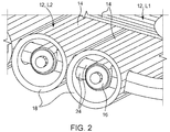
- the individual tanks 14 have connections 16 arranged at the end, which can subsequently be designed as valves 16 which are arranged within structures 18 of the fuel tank 10.
- the structures 18 protect the valves 16 in the event of an increased force being exerted on the fuel tank 10, e.g. B. in an impact. Furthermore, the structures 18 enable the fuel tank 10 to be connected to an adjacent (vehicle) structure and thus serve to transmit power between the (vehicle) structure and the individual tanks 14.
- the structures 18 are structures 20 of the individual tanks 14.
- the structures 20 are designed as extensions of the individual tanks 14 arranged at the end and are integrally connected to them. They can therefore also be referred to as a tank cap 20, a connection cap 20 or a valve cap 20.
- the structures 20 can be designed to be open at the end in order to enable access to the valves 16.
- the structures 20 also have lateral openings 22 which represent passages for supply lines 24 of the fuel tank 10.
- the supply lines 24 can thereby be guided through the structures 20 and connect all the valves 16 of the individual tanks 14 of the respective layer 12 (L1 or L2) to one another.
- Two supply lines 24 can be provided per layer 12, one as an inflow line and one as an outflow line.
- the structures 18 are not part of the individual tanks 14.
- the structures 18 of the fuel tank 10 are designed as auxiliary structures 26 separate from the individual tanks 14 ( Figure 3 ).
- the fact that the auxiliary structures 26 are separate from the individual tanks 14 does not, of course, exclude that these are connected to the individual tanks 14 in a force-conducting manner. Rather, this means that the auxiliary structures 26 are components which are formed independently of the individual tanks 14.
- the individual layers 12 can be connected to one another in a force-conducting manner, for example glued or screwed, in order to further increase the rigidity of the fuel tank 10.
- a vehicle 100 can be seen, which can be designed as a fuel cell vehicle.
- the vehicle 100 includes a fuel cell (not shown) for providing electrical energy for a drive motor (a traction motor, not shown) of the vehicle 100.
- the fuel tank 10 is used to store hydrogen which is converted by the fuel cell into electrical energy during its operation becomes.
- the vehicle 100 has a passenger cell 102 which encloses the seats 104 of the vehicle 100 and thus forms a protected space for vehicle occupants in a known manner.
- the fuel tank 10 is arranged below the seats 104 and the passenger compartment 102.
- the fuel tank 10 can essentially take up the entire area below the passenger cell 102.
- the elongated individual tanks 14 of the first layer L1 thus extend essentially over the entire length of the passenger cell 102, while the individual tanks 14 of the second layer L2 extend essentially over the entire width of the passenger cell 102.
- a power line is provided between a front end 106 and a rear end 108 of the vehicle 100. This is done mainly by means of the first layer L1.
- the two side sills 110 are also connected in a force-conducting manner by means of the fuel tank 10, this being mainly ensured by the second layer L2.
- the orientation O1 corresponds to the first position L1 in the vehicle longitudinal direction FL and the orientation 02 corresponds to a second position L2 of the fuel tank 100 in the vehicle transverse direction FQ.
- the arrangement of the layers L1 and L2 could of course be interchanged so that the second layer L2 is provided above the first layer L1.
- At least one further layer 12 can also be provided.
- the orientation of the at least one further layer could correspond to the orientation O1 or O2 or be different from these.
- increased rigidity of the fuel tank 10 is achieved by the fuel tank 10 according to the invention.
- This increased rigidity can be used to stiffen the vehicle 100 according to the invention and / or to make it lighter. This takes place with at the same time increased safety for passengers of the vehicle 100 in the event of an accident.
Landscapes
- Engineering & Computer Science (AREA)
- Mechanical Engineering (AREA)
- Combustion & Propulsion (AREA)
- Transportation (AREA)
- Chemical & Material Sciences (AREA)
- Sustainable Energy (AREA)
- Life Sciences & Earth Sciences (AREA)
- Sustainable Development (AREA)
- General Engineering & Computer Science (AREA)
- Cooling, Air Intake And Gas Exhaust, And Fuel Tank Arrangements In Propulsion Units (AREA)
- Fuel Cell (AREA)
- Arrangement Or Mounting Of Propulsion Units For Vehicles (AREA)
- Filling Or Discharging Of Gas Storage Vessels (AREA)
Description
- Die Erfindung betrifft einen Brennstofftank und ein Fahrzeug, welches den Brennstofftank aufweist.
- Brennstoffzellen nutzen die chemische Umsetzung eines Brennstoffs mit Sauerstoff zu Wasser, um elektrische Energie zu erzeugen. Hierfür enthalten Brennstoffzellen als Kernkomponente die sogenannte Membran-Elektroden-Anordnung (MEA für membrane electrode assembly), die ein Gefüge aus einer ionenleitenden (meist protonenleitenden) Membran und jeweils einer beidseitig an der Membran angeordneten katalytischen Elektrode (Anode und Kathode) ist. Letztere umfassen zumeist geträgerte Edelmetalle, insbesondere Platin. Zudem können Gasdiffusionslagen (GDL) beidseitig der Membran-Elektroden-Anordnung an den der Membran abgewandten Seiten der Elektroden angeordnet sein. In der Regel wird die Brennstoffzelle durch eine Vielzahl im Stapel (Brennstoffzellenstapel) angeordneter MEAs gebildet, deren elektrische Leistungen sich addieren. Zwischen den einzelnen Membran-Elektroden-Anordnungen sind in der Regel Bipolarplatten (auch Flussfeld- oder Separatorplatten genannt) angeordnet, welche eine Versorgung der Einzelzellen mit den Betriebsmedien, also den Reaktanten, sicherstellen und üblicherweise auch der Kühlung dienen. Zudem sorgen die Bipolarplatten für einen elektrisch leitfähigen Kontakt zu den MembranElektroden-Anordnungen.
- Im Betrieb der Brennstoffzelle wird der Brennstoff (Anodenbetriebsmedium), insbesondere Wasserstoff H2 oder ein wasserstoffhaltiges Gasgemisch, über ein anodenseitiges offenes Flussfeld der Bipolarplatte der Anode zugeführt, wo eine elektrochemische Oxidation von H2 zu Protonen H+ unter Abgabe von Elektronen stattfindet (H2 → 2 H+ + 2 e-). Über den Elektrolyten oder die Membran, welche die Reaktionsräume gasdicht voneinander trennt und elektrisch isoliert, erfolgt ein (wassergebundener oder wasserfreier) Transport der Protonen aus dem Anodenraum in den Kathodenraum. Die an der Anode bereitgestellten Elektronen werden über eine elektrische Leitung der Kathode zugeleitet. Der Kathode wird über ein kathodenseitiges offenes Flussfeld der Bipolarplatte Sauerstoff oder ein sauerstoffhaltiges Gasgemisch (zum Beispiel Luft) als Kathodenbetriebsmedium zugeführt, sodass eine Reduktion von O2 zu O2- unter Aufnahme der Elektronen stattfindet (½ O2 + 2 e- → O2-). Gleichzeitig reagieren im Kathodenraum die Sauerstoffanionen mit den über die Membran transportierten Protonen unter Bildung von Wasser (O2- + 2 H+ → H2O).
- Als Speicher für den Brennstoff wurden bisher CFK Druckspeicher mit einem Maximaldruck von 700 bar im Heck des Fahrzeugs und im Getriebetunnel ohne strukturelle Einbindung verwendet. CFK steht für carbonfaserverstärkter Kunststoff oder kohlenstofffaserverstärkter Kunststoff. Ebenso ist eine nichtstrukturelle Einbindung von Metallhydridspreichern bekannt. Auch ist eine strukturelle Einbindung am Verbauort bekannt, die nicht wesentlich zur Gesamtsteifigkeit beiträgt. Daraus ergeben sich Nachteile bezüglich eines geringeren Innenraumvolumens und zudem Bauraumeinschränkungen. Ferner werden potentielle Struktureinsparungen nicht genutzt.
- Um dies zu kompensieren wurden bisher mehrere kleinere Tanks anstelle eines einzelnen Tanks zur Darstellung der gewünschten Kapazität und Reichweite verwendet, was für sich betrachtet zu einer deutlichen Kostensteigerung führt. Ferner wurden Kohlefasertanks eingesetzt, um den Gewichtsnachteil kleinerer Tanks mit geringerem Nutzvolumenverhältnis zum benötigten Bauraum auszugleichen.
-
DE 10 2005 003 669 A1 offenbart ein Kraftfahrzeug mit einem Rahmenzusammenbau, wobei ein Fluidspeichervolumen für Brennstoff in einem länglichen Schienenabschnitt des Rahmenzusammenbaus definiert ist. -
DE 10 2011 051 436 A1 offenbart einen Wasserstoffspeicher (ein Druckspeicher) für ein Fahrzeug, welcher als eine Verstärkung eines Rahmens einer tragenden Struktur dient. Im Falle eines Aufpralls des Fahrzeugs auf ein Hindernis versagen Verbindungselemente, bevor eine zu hohe Kraft in den Druckspeicher eingeleitet wird, welche zu einer Beschädigung des Druckspeichers führen könnte. - In den Dokumenten
US 2013/224410 A1 ,EP 2 508 381 A2 ,DE 20 2006 004434 U1 ,WO 2005/079540 A2 ,WO 03/085314 A2 FR 2 857 630 A1 EP 1 431 096 A2 undJP 2004 017669 A - Auch in
EP 3 346 179 A1 wird ein derartiger Brennstofftank mit aufeinandergestapelten Lagen von Einzeltanks beschrieben, wobei die Orientierungen der Lagen einen Winkel von 90° zueinander aufweisen. - Der Erfindung liegt nun die Aufgabe zugrunde, einen Brennstofftank vorzuschlagen, welcher eine erhöhte Steifigkeit gegenüber bekannten Brennstofftanks aufweist.
- Diese Aufgabe wird durch einen Brennstofftank mit den Merkmalen des unabhängigen Anspruchs gelöst.
- Erfindungsgemäß wird ein Brennstofftank mit wenigstens zwei aufeinandergestapelten Lagen zur Verfügung gestellt, wobei die Lagen jeweils mehrere aneinandergereihte Einzeltanks aufweisen. Die Einzeltanks sind länglich ausgebildet und eine Längserstreckung der länglichen Einzeltanks definiert eine Orientierung der jeweiligen Lage, wobei die wenigstens zwei Lagen eine unterschiedliche Orientierung aufweisen und die Orientierungen der Lagen einen Winkel von 90° zueinander aufweisen. Mehrere Einzeltanks einer Lage weisen einen stirnseitig angeordneten Anschluss auf, welcher innerhalb einer Struktur des Brennstofftanks angeordnet ist. Die Struktur ist eine von den Einzeltanks separate Hilfsstruktur, die als Schiene ausgebildet ist und innerhalb welcher mehrere Anschlüsse der Einzeltanks einer Lage angeordnet sind.
- Dadurch, dass der Brennstofftank zwei aufeinandergestapelte Lagen, also zwei Lagen deren Hauptflächen (die größten Flächen) sich gegenüberstehen, aufweist, wird eine Steifigkeit, insbesondere eine Biegesteifigkeit des Tanks stark erhöht. Die Lagen sind insbesondere planparallel zueinander angeordnet. Es besteht die Möglichkeit einer Strukturintegration in eine Fahrgastzelle eines Fahrzeugs, also einer Aussteifung der Fahrgastzelle. Dass die Lagen aufeinandergestapelt sind, bedeutet nicht zwangsläufig, dass die Lagen räumlich übereinandergestapelt sind, wobei dies aber dennoch der Fall sein kann. Vielmehr kann dies bedeuten, dass Hauptflächen der wenigstens zwei Lagen flächig aneinandergereiht sind. Die Einzeltanks sind insbesondere parallel aneinandergereiht, wodurch die Lage optimal mit Einzeltanks gefüllt ist. Die Lagen erstrecken sich insbesondere innerhalb einer Ebene, weisen also eine ebene Erstreckung auf.
- Die Einzeltanks sind länglich (ausgebildet). Dass die Einzeltanks länglich sind, bedeutet, dass deren Länge größer ist als ihre Breite, Dicke oder ihr Durchmesser. Vorzugsweise ist die Länge der Einzeltanks wenigstens fünfmal, insbesondere wenigstens zehnmal, besonders bevorzugt wenigstens zwanzigmal so groß wie ihre Breite, Dicke oder ihr Durchmesser. Die Einzeltanks können dabei einen rechteckigen, insbesondere quadratischen, oder runden Querschnitt aufweisen. Die Einzeltanks können auch als einzelne Tanks bezeichnet werden, stellen also insbesondere voneinander getrennte Volumen dar. Die länglichen Einzeltanks sind vorzugsweise so aneinandergereiht, dass Längsseiten der Einzeltanks aneinandergereiht sind, wodurch ein kompakter Brennstofftank geschaffen wird.
- Die Einzeltanks sind insbesondere Metall-Hydrid-Energiespeicher. Derartige Einzeltanks eignen sich besonders zum Speichern von Wasserstoff.
- Bevorzugt sind die einzelnen Lagen und/oder die Einzeltanks kräfteleitend miteinander verbunden, insbesondere verklebt oder verschraubt, um die Steifigkeit des Brennstofftanks als Gesamtes weiter zu erhöhen.
- Es ist vorgesehen, dass eine Längserstreckung der länglichen Einzeltanks eine Orientierung der jeweiligen Lage definiert und die wenigstens zwei Lagen eine unterschiedliche Orientierung aufweisen. Die Einzeltanks einer der Lagen sind also zu den Einzeltanks der wenigstens einen anderen Lage quer (verdreht) angeordnet. Dadurch wird der Brennstofftank noch steifer, insbesondere in einer zweiten Richtung biegesteifer, wodurch die Aussteifung (Versteifung) der Fahrgastzelle weiter erhöht werden kann.
- Dabei ist vorgesehen, dass die Orientierungen der Lagen einen Winkel von 90° zueinander aufweisen. Die Einzeltanks sind also in mehreren zueinander um 90° gedrehten Lagen angeordnet. Damit wird eine optimale Steifigkeit des Brennstofftanks erreicht, da der Brennstofftank in zwei rechtwinkelig zueinander angeordneten Richtungen ausgesteift ist. Dadurch kann eine besonders gute Strukturintegration, also Aussteifung, einer Fahrgastzelle eines Fahrzeugs erreicht werden.
- Es ist vorgesehen, dass wenigstens mehrere der Einzeltanks einen stirnseitig angeordneten Anschluss aufweisen, welcher innerhalb der Struktur des Brennstofftanks angeordnet ist. Die Struktur ist insbesondere dazu ausgebildet, von außerhalb des Brennstofftanks auf diesen einwirkende Kräfte an die Einzeltanks weiterzuleiten. Dabei ist die Struktur insbesondere so (steif) ausgeführt, dass der Anschluss vor den Kräften geschützt ist. Der Anschluss dient insbesondere zum Befüllen und/oder Entleeren des Einzeltanks.
- Vorzugsweise ist der Anschluss als eine Verschraubung ausgebildet, welche eine besonders einfache Variante des Anschlusses darstellt. Insbesondere umfasst der Anschluss ein Ventil oder ist als ein Ventil ausgebildet. Dies ist besonders vorteilhaft, da verglichen mit einem Betrieb der Brennstoffzelle, Betriebsdrücke bei einem Betanken des Brennstofftanks relativ hoch sind.
- Es ist vorgesehen, dass die Struktur des Brennstofftanks eine von den Einzeltanks separate Hilfsstruktur ist. Somit stellt der Anschluss einen außenliegenden Anschluss (außerhalb des Einzeltanks) dar, welches durch zusätzliche strukturelle Maßnahmen, also die Hilfsstruktur, insbesondere durch einen Hilfsrahmen, geschützt wird. Dadurch werden der Konstruktionsaufwand und somit die Kosten des Einzeltanks reduziert. Die Hilfsstruktur ist als eine Schiene ausgebildet, innerhalb welcher mehrere, insbesondere alle Anschlüsse der Einzeltanks (einer Lage) angeordnet sind.
- Es ist vorgesehen, dass der der wenigstens eine Einzeltank wenigstens eine Versorgungsleitung aufweist, welche quer zu einer Längserstreckung der Einzeltanks durch die Struktur geführt wird. Die wenigstens eine Versorgungsleitung umfasst insbesondere zwei Versorgungsleitungen (insbesondere eine Zu- und eine Ableitung), welche die Anschlüsse (insbesondere Ventile) der Einzeltanks (einer Lage) miteinander verbinden können. Die Versorgungsleitungen (für den Brennstoff) werden bei einer als Tankkappe ausgebildeten Struktur (also bei einer integralen Struktur des Einzeltanks) durch seitliche Öffnungen der Tankkappe und insbesondere von einer Tankkappe zur nächsten Tankkappe geführt. Diese Struktur ist als Schiene ausgebildet, so können die Versorgungsleitungen innerhalb der Schiene und von dieser geschützt geführt werden.
- Alle Einzeltanks weisen den genannten stirnseitig angeordneten Anschluss auf, wobei die Anschlüsse, insbesondere alle, innerhalb einer oder mehrerer der genannten Strukturen angeordnet und von dieser oder diesen geschützt werden.
- Ferner wird ein Fahrzeug umfassend einen erfindungsgemäßen Brennstofftank zur Verfügung gestellt. Vorzugsweise ist das Fahrzeug ein Brennstoffzellenfahrzeug. Dieses weist typischerweise eine Brennstoffzelle zur Bereitstellung von elektrischer Energie für einen (elektrischen) Antriebsmotor des Fahrzeugs auf. Der Brennstofftank ist somit zur Speicherung eines Brennstoffs, insbesondere von Wasserstoff, für die Brennstoffzelle eingerichtet. Der Wasserstoff dient also als Treibstoff für das Brennstoffzellenfahrzeug. Durch die Erfindung wird somit ein besonders steifes Brennstoffzellenfahrzeug geschaffen, welches sich durch seine verringerte Masse bei gleichzeitig erhöhter Verformungsresistenz, insbesondere bei einem Unfall, auszeichnet.
- Der Brennstofftank ist vorzugsweise in eine tragende Struktur des Fahrzeugs, also beispielsweise sein Chassis, seine Fahrgastzelle oder seinen Rahmen strukturell integriert. Dadurch wird die tragende Struktur des Fahrzeugs versteift. Mit anderen Worten bildet der Brennstofftank einen Teil der tragenden Struktur des Fahrzeugs.
- Vorzugsweise dient der Brennstofftank als Lastpfad bei einem Anprall (Crash), sowohl bei einem Seiten- als auch Frontalanprall.
- Bevorzugt ist der Brennstofftank derart im Fahrzeug angeordnet, dass die aufeinandergestapelten Lagen übereinander angeordnet sind, wodurch eine kompakte Einbaulage des Brennstofftanks gewährleistet ist.
- Vorzugsweise ist vorgesehen, dass das Fahrzeug eine Fahrgastzelle umfasst, unterhalb welcher der Brennstofftank angeordnet ist. Somit ist der Brennstofftank insbesondere in die tragende Struktur eines Unterbodens des Fahrzeugs integriert. Dadurch werden eine Gewichtseinsparung im Bereich des Mittelwagens (also im Bereich der Fahrgastzelle) und zudem ein größerer nutzbarer Fahrzeuginnenraum erreicht.
- Bevorzugt ist vorgesehen, dass die Orientierung einer der Lagen der Fahrzeuglängsrichtung und die Orientierung einer anderen Lage des Brennstofftanks der Fahrzeugquerrichtung entspricht. Somit wird das Fahrzeug sowohl in Fahrzeuglängsrichtung als auch in Fahrzeugquerrichtung versteift. Zudem wird die Fahrgastzelle sowohl bei einem Seiten- als auch Frontalanprall besser vor Verformungen geschützt.
- Vorzugsweise ist dabei vorgesehen, dass sich die Einzeltanks jener Lage mit der Orientierung in Fahrzeuglängsrichtung über die gesamte Länge der Fahrgastzelle erstrecken. Ferner bevorzugt ist vorgesehen, dass sich die Einzeltanks jener Lage mit der Orientierung in Fahrzeugquerrichtung über die gesamte Breite (insbesondere zwischen Seitenschwellern des Fahrzeugs) der Fahrgastzelle erstrecken. Somit wird die Fahrgastzelle optimal ausgesteift (versteift) und bei einem Anprall geschützt.
- Weitere bevorzugte Ausgestaltungen der Erfindung ergeben sich aus den übrigen, in den Unteransprüchen genannten Merkmalen.
- Die verschiedenen in dieser Anmeldung genannten Ausführungsformen der Erfindung sind, sofern im Einzelfall nicht anders ausgeführt, mit Vorteil miteinander kombinierbar.
- Die Erfindung wird nachfolgend in Ausführungsbeispielen anhand der zugehörigen Zeichnungen erläutert. Es zeigen:
- Figur 1
- einen Brennstofftank gemäß einer nicht zur Erfindung gehörenden Ausgestaltung;
- Figur 2
- eine Detailansicht des Brennstofftanks nach
Figur 1 ; - Figur 3
- einen Brennstofftank gemäß einer erfindungsgemäßen Ausgestaltung; und
- Figur 4
- eine schematische Darstellung eines Fahrzeugs gemäß einer bevorzugten Ausgestaltung.
-
Figur 1 zeigt einen Brennstofftank 10 gemäß einer nicht zur vorliegenden Erfindung gehörenden Ausgestaltung. Der Brennstofftank 10 weist wenigstens zwei aufeinandergestapelte Lagen 12 auf, wobei jede der Lagen 12 jeweils mehrere parallel aneinandergereihte Einzeltanks 14 aufweist. Die Einzeltanks 14 sind länglich ausgebildet und so aneinandergereiht, dass Längsseiten der Einzeltanks 14 aneinandergereiht sind. Die Einzeltanks 14 können als Metall-Hydrid-Speicher, beispielsweise zum Speichern von Wasserstoff ausgebildet sein. Das Metall-Hydrid ist dabei in den als hohle Stangen ausgebildeten Einzeltanks 14 angeordnet. - Eine Längserstreckung der länglichen Einzeltanks 14 definiert eine Orientierung O1 oder 02 der jeweiligen Lage L1 oder L2. Die beiden Lagen L1 und L2 weisen dabei eine unterschiedliche Orientierung auf. Die Orientierungen O1 und O2 schließen also einen Winkel ein, welcher im dargestellten Fall 90° (Grad) beträgt. Es ist leicht ersichtlich, dass die einzelnen Lagen je nach Belastungsrichtung eine unterschiedliche Steifigkeit aufweisen. Dadurch, dass die beiden Lagen 12 um 90° zueinander verdreht angeordnet sind, weist der Brennstofftank 10 in zwei orthogonalen Richtung in etwa dieselbe Steifigkeit auf.
- Die Einzeltanks 14 weisen stirnseitig angeordnete Anschlüsse 16 auf, welche folgend als Ventile 16 ausgebildet sein können, welche innerhalb von Strukturen 18 des Brennstofftanks 10 angeordnet sind. Die Strukturen 18 schützt die Ventile 16 im Falle einer gesteigerten Krafteinwirkung auf den Brennstofftank 10, z. B. bei einem Anprall. Ferner ermöglichen die Strukturen 18 eine Anbindung des Brennstofftanks 10 an eine angrenzende (Fahrzeug-) Struktur und dienen so zur Kraftweiterleitung zwischen der (Fahrzeug-) Struktur und den Einzeltanks 14.
- Wie in
Figur 1 und insbesondere inFigur 2 ersichtlich ist, sind die Strukturen 18 Strukturen 20 der Einzeltanks 14. Die Strukturen 20 sind dazu als stirnseitig angeordnete Fortsätze der Einzeltanks 14 ausgebildet und mit diesen integral verbunden. Sie können somit auch als Tankkappe 20, Anschlusskappe 20 oder Ventilkappe 20 bezeichnet werden. Die Strukturen 20 können stirnseitig offen ausgebildet sein, um einen Zugang zu den Ventilen 16 zu ermöglichen. - Ferner weisen die Strukturen 20 seitliche Öffnungen 22 auf, welche Durchlässe für Versorgungsleitungen 24 des Brennstofftanks 10 darstellen. Die Versorgungsleitungen 24 können dadurch durch die Strukturen 20 geführt werden und alle Ventile 16 der Einzeltanks 14 der jeweiligen Lage 12 (L1 oder L2) miteinander verbinden. Pro Lage 12 können dabei zwei Versorgungsleitungen 24 vorgesehen sein, eine als Zufluss- und eine als Abflussleitung.
- Die Strukturen 18 sind erfindungsgemäß nicht Bestandteil der Einzeltanks 14. Die Strukturen 18 des Brennstofftanks 10 sind als von den Einzeltanks 14 separate Hilfsstrukturen 26 ausgebildet (
Figur 3 ). Dass die Hilfsstrukturen 26 von den Einzeltanks 14 separat sind, schließt natürlich nicht aus, dass diese mit den Einzeltanks 14 kräfteleitend verbunden sind. Vielmehr bedeutet dies, dass als Hilfsstrukturen 26 Bauteile vorgesehen sind, welche von den Einzeltanks 14 unabhängig ausgeformt sind. - Die einzelnen Lagen 12 (L1 und L2) können kräfteleitend miteinander verbunden, beispielsweise verklebt oder verschraubt sein, um die Steifigkeit des Brennstofftanks 10 weiter zu erhöhen.
- In
Figur 4 ist ein Fahrzeug 100 ersichtlich, welches als ein Brennstoffzellenfahrzeug ausgebildet sein kann. Das Fahrzeug 100 umfasst in diesem Fall eine Brennstoffzelle (nicht dargestellt) zur Bereitstellung von elektrischer Energie für einen Antriebsmotor (ein nicht dargestellter Traktionsmotor) des Fahrzeugs 100. Der Brennstofftank 10 dient zur Speicherung von Wasserstoff welcher von der Brennstoffzelle bei deren Betrieb zu elektrischer Energie umgesetzt wird. - Das Fahrzeug 100 weist eine Fahrgastzelle 102 auf, welche die Sitze 104 des Fahrzeugs 100 umschließt und so in bekannter Weise einen geschützten Raum für Fahrzeuginsassen bildet. Unterhalb der Sitze 104 und der Fahrgastzelle 102 ist der Brennstofftank 10 angeordnet. Der Brennstofftank 10 kann dabei im Wesentlichen die gesamte Fläche unterhalb der Fahrgastzelle 102 einnehmen. Die länglichen Einzeltanks 14 der ersten Lage L1 erstrecken sich somit im Wesentlichen über die gesamte Länge der Fahrgastzelle 102, währen sich die Einzeltanks 14 der zweiten Lage L2 im Wesentlichen über die gesamte Breite der Fahrgastzelle 102 erstrecken. Somit ist mittels des Brennstofftanks 10 eine Kraftleitung zwischen einem Vorderwagen 106 und einem Hinterwagen 108 des Fahrzeugs 100 gegeben. Dies erfolgt hauptsächlich mittels der ersten Lage L1. Ferner sind auch die beiden Seitenschweller 110 kräfteleitend mittels des Brennstofftanks 10 verbunden, wobei dies hauptsächlich durch die zweite Lage L2 gewährleistet wird.
- Dazu entspricht die Orientierung O1 der ersten Lage L1 der Fahrzeuglängsrichtung FL und die Orientierung 02 einer zweiten Lage L2 des Brennstofftanks 100 der Fahrzeugquerrichtung FQ. Natürlich könnten die Lagen L1 und L2 in ihrer Anordnung vertauscht werden, sodass die zweite Lage L2 oberhalb der ersten Lage L1 vorgesehen ist.
- Ferner könnte in den Ausgestaltungen gemäß den
Figuren 1 bis 4 noch wenigstens eine weitere Lage 12 vorgesehen sein. Die Orientierung der wenigstens einen weiteren Lage könnte dabei der Orientierung O1 oder 02 entsprechen oder von diesen verschieden sein. - Insgesamt wird durch den erfindungsgemäßen Brennstofftank 10 eine erhöhte Steifigkeit des Brennstofftanks 10 erreicht. Diese erhöhte Steifigkeit kann dazu genutzt werden, um das erfindungsgemäße Fahrzeug 100 zu versteifen und/oder leichter zu gestalten. Dies erfolgt bei gleichzeitig erhöhter Sicherheit für Passagiere des Fahrzeugs 100 im Falle eines Unfalls.
-
- 10
- Brennstofftank
- 12
- Lage
- 14
- Einzeltank
- 16
- Anschluss / Ventil
- 18
- Struktur des Brennstofftanks
- 20
- Struktur des Einzeltanks / Tankkappe / Anschlusskappe / Ventilkappe
- 22
- Öffnungen
- 24
- Versorgungsleitungen
- 26
- Hilfsstruktur
- L1
- erste Lage
- L2
- zweite Lage
- O1
- erste Orientierung / Orientierung der ersten Lage
- O2
- zweite Orientierung / Orientierung der zweiten Lage
- 100
- Fahrzeug
- 102
- Fahrgastzelle
- 104
- Sitze
- 106
- Vorderwagen
- 108
- Hinterwagen
- 110
- Seitenschweller
Claims (5)
- Brennstofftank (10) mit wenigstens zwei aufeinandergestapelten Lagen (12), wobei die Lagen (12) jeweils mehrere aneinandergereihte Einzeltanks (14) aufweisen, wobei die Einzeltanks (14) länglich ausgebildet sind und eine Längserstreckung der länglichen Einzeltanks (14) eine Orientierung (O1 oder 02) der jeweiligen Lage (L1 oder L2) definiert, wobei die wenigstens zwei Lagen (12) eine unterschiedliche Orientierung (O1, 02) aufweisen und wobei die Orientierungen (O1, 02) der Lagen (12) einen Winkel von 90° zueinander aufweisen, dadurch gekennzeichnet, dass mehrere Einzeltanks (14) einer Lage (12) einen stirnseitig angeordneten Anschluss (16) aufweisen, welcher innerhalb einer Struktur (18) des Brennstofftanks (10) angeordnet ist, wobei die Struktur (18) des Brennstofftanks (10) eine von den Einzeltanks (14) separate Hilfsstruktur (26) ist, die als Schiene ausgebildet ist und innerhalb welcher mehrere Anschlüsse (16) der Einzeltanks (14) einer Lage (12) angeordnet sind.
- Brennstofftank (10) nach Anspruch 1, dadurch gekennzeichnet, dass der wenigstens eine Einzeltank (14) wenigstens eine Versorgungsleitung (24) aufweist, welche quer zu einer Längserstreckung der Einzeltanks (14) durch die Struktur (18) geführt wird.
- Fahrzeug (100), insbesondere Brennstoffzellenfahrzeug, umfassend einen Brennstofftank (10) nach einem der vorhergehenden Ansprüche.
- Fahrzeug (100) nach Anspruch 3, dadurch gekennzeichnet, dass das Fahrzeug (100) eine Fahrgastzelle (102) umfasst, unterhalb welcher der Brennstofftank (10) angeordnet ist.
- Fahrzeug (100) nach einem der Ansprüche 3 oder 4, dadurch gekennzeichnet, dass die Orientierung (O1) einer der Lagen (L1) der Fahrzeuglängsrichtung (FL) und die Orientierung (02) einer anderen Lage (L2) der Fahrzeugquerrichtung (FQ) entspricht.
Applications Claiming Priority (2)
| Application Number | Priority Date | Filing Date | Title |
|---|---|---|---|
| DE102017214606.0A DE102017214606A1 (de) | 2017-08-22 | 2017-08-22 | Brennstofftank und Fahrzeug |
| PCT/EP2018/072324 WO2019038198A1 (de) | 2017-08-22 | 2018-08-17 | Brennstofftank und fahrzeug |
Publications (2)
| Publication Number | Publication Date |
|---|---|
| EP3595921A1 EP3595921A1 (de) | 2020-01-22 |
| EP3595921B1 true EP3595921B1 (de) | 2021-03-31 |
Family
ID=63407191
Family Applications (1)
| Application Number | Title | Priority Date | Filing Date |
|---|---|---|---|
| EP18762035.6A Active EP3595921B1 (de) | 2017-08-22 | 2018-08-17 | Brennstofftank und fahrzeug |
Country Status (7)
| Country | Link |
|---|---|
| US (1) | US10850611B2 (de) |
| EP (1) | EP3595921B1 (de) |
| JP (1) | JP6845374B2 (de) |
| KR (1) | KR102148210B1 (de) |
| CN (1) | CN110944865B (de) |
| DE (1) | DE102017214606A1 (de) |
| WO (1) | WO2019038198A1 (de) |
Families Citing this family (6)
| Publication number | Priority date | Publication date | Assignee | Title |
|---|---|---|---|---|
| DE102019130030A1 (de) | 2019-11-07 | 2021-05-12 | Bayerische Motoren Werke Aktiengesellschaft | Kraftfahrzeug |
| JP7327189B2 (ja) * | 2020-02-05 | 2023-08-16 | トヨタ自動車株式会社 | 高圧容器搭載構造 |
| JP7722813B2 (ja) * | 2020-06-24 | 2025-08-13 | トヨタ自動車株式会社 | 輸送車両 |
| US11703185B2 (en) * | 2021-03-22 | 2023-07-18 | Ezng Solutions, Llc | Apparatus, systems, and methods for storing and transporting compressed fluids |
| JP2024031513A (ja) * | 2022-08-26 | 2024-03-07 | トヨタ自動車株式会社 | カードル |
| US20240400136A1 (en) * | 2023-06-01 | 2024-12-05 | Hummingbird Ev | Modular vehicle multi-plane chassis system |
Family Cites Families (25)
| Publication number | Priority date | Publication date | Assignee | Title |
|---|---|---|---|---|
| US4664987A (en) * | 1984-11-15 | 1987-05-12 | Westinghouse Electric Corp. | Fuel cell arrangement |
| PL341261A1 (en) * | 2000-07-05 | 2002-01-14 | Jacek Staniuk | Pressure vessel in particular that for storing liquefied gas |
| GB2374056B (en) * | 2001-04-06 | 2004-08-18 | Darchem Engineering Ltd | Impact-resistant fuel tank device |
| US6974156B2 (en) * | 2002-03-19 | 2005-12-13 | Honda Giken Kogyo Kabushiki Kaisha | Fuel tank structure |
| FR2838177B1 (fr) * | 2002-04-08 | 2004-09-03 | Snecma Propulsion Solide | Reservoir pour fluide sous pression, notamment reservoir pour gaz comprime destine a un vehicule automobile |
| JP3908985B2 (ja) | 2002-06-12 | 2007-04-25 | 本田技研工業株式会社 | 燃料タンク装置 |
| EP1431096A3 (de) * | 2002-12-18 | 2006-04-26 | Conception et Développement Michelin S.A. | Hochdruckspeicherbehälter zur Lagerung von Kraftstoff auf einem Kraftfahrzeug |
| FR2857630B1 (fr) * | 2003-07-18 | 2006-10-27 | Gie Psa Peugeot Citroen | Vehicule automobile muni d'un reservoir de gaz, a securite renforcee |
| US20050161267A1 (en) | 2004-01-28 | 2005-07-28 | Gerald Elson | Fluid storage for fuel cell vehicles using closed section structural body rails |
| US7146817B2 (en) * | 2004-02-19 | 2006-12-12 | Mustang Engineering L.P. | Cold box storage apparatus for LNG tanks and methods for processing, transporting and/or storing LNG |
| DE202006004434U1 (de) * | 2006-03-21 | 2006-06-08 | Otto Fuchs Kg | Kraftstoffbehälteranordnung zum Speichern druckbeaufschlagter Gase für ein Kraftfahrzeug |
| DE102006019014A1 (de) | 2006-04-20 | 2007-10-25 | Fraunhofer-Gesellschaft zur Förderung der angewandten Forschung e.V. | Speichermodul für komprimierte fluidische Kraftstoffe |
| WO2009017147A1 (ja) * | 2007-08-02 | 2009-02-05 | Sharp Kabushiki Kaisha | 燃料電池スタックおよび燃料電池システム |
| CN102388256B (zh) * | 2009-04-10 | 2015-03-18 | 丰田自动车株式会社 | 罐及其制造方法 |
| JP5824240B2 (ja) * | 2010-05-11 | 2015-11-25 | 株式会社キーレックス | 車両用高圧タンク |
| EP2508381B1 (de) * | 2011-04-05 | 2014-07-02 | Magna Steyr Fahrzeugtechnik AG & Co KG | Kraftfahrzeug mit einer Drucktankvorrichtung |
| DE102011051436B4 (de) | 2011-06-29 | 2021-06-10 | Deutsches Zentrum für Luft- und Raumfahrt e.V. | Fahrzeug |
| US8917809B2 (en) * | 2012-02-28 | 2014-12-23 | Tsukasa NOZAWA | Honeycomb structure having honeycomb core arranged parallel to a panel surface and a manufacturing process therefor |
| WO2015017844A1 (en) * | 2013-08-02 | 2015-02-05 | Alternative Fuel Containers, Llc | Conformable fuel gas tank |
| JP6432541B2 (ja) * | 2016-02-18 | 2018-12-05 | トヨタ自動車株式会社 | ガスタンク搭載車両 |
| JP6439986B2 (ja) * | 2016-02-22 | 2018-12-19 | トヨタ自動車株式会社 | 燃料電池車 |
| US9878611B1 (en) * | 2016-07-29 | 2018-01-30 | GM Global Technology Operations LLC | Vehicle with natural gas storage array |
| JP2018112201A (ja) * | 2017-01-06 | 2018-07-19 | トヨタ自動車株式会社 | 高圧容器及び高圧容器製造方法 |
| JP6881144B2 (ja) * | 2017-08-09 | 2021-06-02 | トヨタ自動車株式会社 | 高圧タンク搭載構造 |
| US10589788B1 (en) * | 2019-01-29 | 2020-03-17 | Nikola Motor Company Llc | Vehicle frame arrangement |
-
2017
- 2017-08-22 DE DE102017214606.0A patent/DE102017214606A1/de not_active Withdrawn
-
2018
- 2018-08-17 JP JP2020505489A patent/JP6845374B2/ja not_active Expired - Fee Related
- 2018-08-17 KR KR1020207005120A patent/KR102148210B1/ko not_active Expired - Fee Related
- 2018-08-17 CN CN201880054549.5A patent/CN110944865B/zh not_active Expired - Fee Related
- 2018-08-17 WO PCT/EP2018/072324 patent/WO2019038198A1/de not_active Ceased
- 2018-08-17 EP EP18762035.6A patent/EP3595921B1/de active Active
- 2018-08-17 US US16/639,092 patent/US10850611B2/en not_active Expired - Fee Related
Non-Patent Citations (1)
| Title |
|---|
| None * |
Also Published As
| Publication number | Publication date |
|---|---|
| KR102148210B1 (ko) | 2020-08-27 |
| JP2020528383A (ja) | 2020-09-24 |
| CN110944865B (zh) | 2021-05-07 |
| KR20200030109A (ko) | 2020-03-19 |
| US10850611B2 (en) | 2020-12-01 |
| CN110944865A (zh) | 2020-03-31 |
| EP3595921A1 (de) | 2020-01-22 |
| WO2019038198A1 (de) | 2019-02-28 |
| JP6845374B2 (ja) | 2021-03-17 |
| DE102017214606A1 (de) | 2019-02-28 |
| US20200231034A1 (en) | 2020-07-23 |
Similar Documents
| Publication | Publication Date | Title |
|---|---|---|
| EP3595921B1 (de) | Brennstofftank und fahrzeug | |
| DE102016203890A1 (de) | Karosseriestrukturelement für ein Fahrzeug mit integriertem Befeuchter | |
| DE102017128829A1 (de) | Brennstoffzellenfahrzeug | |
| EP3740992B1 (de) | Bipolarplatte, brennstoffzelle und ein kraftfahrzeug | |
| DE102015215231A1 (de) | Bipolarplatte sowie Brennstoffzellensystem mit einer solchen | |
| DE112008000472T5 (de) | Brennstoffzelle und Befestigungsvorrichtung für eine Brennstoffzelle | |
| DE102016111638A1 (de) | Bipolarplatte mit variabler Breite der Reaktionsgaskanäle im Eintrittsbereich des aktiven Bereichs, Brennstoffzellenstapel und Brennstoffzellensystem mit solchen Bipolarplatten sowie Fahrzeug | |
| DE102016121506A1 (de) | Bipolarplatte sowie Brennstoffzelle mit einer solchen | |
| EP3736894B1 (de) | Bipolarplatte für brennstoffzellen, brennstoffzellenstapel mit solchen bipolarplatten sowie fahrzeug mit einem solchen brennstoffzellenstapel | |
| DE102008004698A1 (de) | Konisch geformter Brennstoffspeichertank | |
| DE102013209378B4 (de) | Brennstoffzellenstapel zum Verhindern der Verschlechterung einer Endzelle | |
| DE102023125496A1 (de) | Brennstoffzellenfahrzeug | |
| DE102019205069A1 (de) | Bipolarplatte für Brennstoffzellen, Brennstoffzellenstapel mit solchen Bipolarplatten sowie Fahrzeug mit einem solchen Brennstoffzellenstapel | |
| DE10010398A1 (de) | Kraftfahrzeug | |
| DE102023201535A1 (de) | Rahmenstruktur, Membran-Elektroden-Anordnung für eine Elektrolysezelle und Stapel von Elektrolysezellen | |
| DE102018211078B3 (de) | Bipolarplatte für Brennstoffzellen mit drei Einzelplatten, sowie Brennstoffzelle und Brennstoffzellenstapel mit solchen Bipolarplatten | |
| DE102020212533A1 (de) | Brennstoffzelle mit reduzierendem Strömungsquerschnitt | |
| DE102019206117A1 (de) | Brennstoffzellenstapel umfassend variable Biopolarplatten | |
| DE112004001990T5 (de) | Brennstoffzellenstapel mit reduziertem Volumen | |
| DE102022118660B4 (de) | Brennstoffzellenanordnung, Brennstoffzellenvorrichtung und Kraftfahrzeug | |
| EP4244923B1 (de) | Brennstoffzellenstapel mit komprimierbarer gewebestruktur | |
| DE102008046402A1 (de) | Eiförmiger Brennstoffspeichertank | |
| DE102013203311A1 (de) | Brennstoffzellensystem | |
| DE102019203321A1 (de) | Brennstoffzellenplatte, Brennstoffzellenaufbau und Brennstoffzellensystem | |
| DE102020127464A1 (de) | Bipolarplatte mit orthogonalen Kühlmittelkanälen, Brennstoffzellenaufbau und Brennstoffzellenstapel |
Legal Events
| Date | Code | Title | Description |
|---|---|---|---|
| STAA | Information on the status of an ep patent application or granted ep patent |
Free format text: STATUS: UNKNOWN |
|
| STAA | Information on the status of an ep patent application or granted ep patent |
Free format text: STATUS: THE INTERNATIONAL PUBLICATION HAS BEEN MADE |
|
| PUAI | Public reference made under article 153(3) epc to a published international application that has entered the european phase |
Free format text: ORIGINAL CODE: 0009012 |
|
| STAA | Information on the status of an ep patent application or granted ep patent |
Free format text: STATUS: REQUEST FOR EXAMINATION WAS MADE |
|
| 17P | Request for examination filed |
Effective date: 20191015 |
|
| AK | Designated contracting states |
Kind code of ref document: A1 Designated state(s): AL AT BE BG CH CY CZ DE DK EE ES FI FR GB GR HR HU IE IS IT LI LT LU LV MC MK MT NL NO PL PT RO RS SE SI SK SM TR |
|
| AX | Request for extension of the european patent |
Extension state: BA ME |
|
| STAA | Information on the status of an ep patent application or granted ep patent |
Free format text: STATUS: EXAMINATION IS IN PROGRESS |
|
| 17Q | First examination report despatched |
Effective date: 20200129 |
|
| RIN1 | Information on inventor provided before grant (corrected) |
Inventor name: SCHOENWALD, CHRISTIAN Inventor name: KRAUS, MAIK Inventor name: BUCHHOLZ, ANDRE Inventor name: SARIOGLU, ISMAIL LEVENT |
|
| DAV | Request for validation of the european patent (deleted) | ||
| DAX | Request for extension of the european patent (deleted) | ||
| GRAP | Despatch of communication of intention to grant a patent |
Free format text: ORIGINAL CODE: EPIDOSNIGR1 |
|
| STAA | Information on the status of an ep patent application or granted ep patent |
Free format text: STATUS: GRANT OF PATENT IS INTENDED |
|
| GRAS | Grant fee paid |
Free format text: ORIGINAL CODE: EPIDOSNIGR3 |
|
| INTG | Intention to grant announced |
Effective date: 20210128 |
|
| GRAA | (expected) grant |
Free format text: ORIGINAL CODE: 0009210 |
|
| STAA | Information on the status of an ep patent application or granted ep patent |
Free format text: STATUS: THE PATENT HAS BEEN GRANTED |
|
| AK | Designated contracting states |
Kind code of ref document: B1 Designated state(s): AL AT BE BG CH CY CZ DE DK EE ES FI FR GB GR HR HU IE IS IT LI LT LU LV MC MK MT NL NO PL PT RO RS SE SI SK SM TR |
|
| REG | Reference to a national code |
Ref country code: GB Ref legal event code: FG4D Free format text: NOT ENGLISH Ref country code: CH Ref legal event code: EP |
|
| REG | Reference to a national code |
Ref country code: DE Ref legal event code: R096 Ref document number: 502018004580 Country of ref document: DE Ref country code: AT Ref legal event code: REF Ref document number: 1376552 Country of ref document: AT Kind code of ref document: T Effective date: 20210415 |
|
| REG | Reference to a national code |
Ref country code: IE Ref legal event code: FG4D Free format text: LANGUAGE OF EP DOCUMENT: GERMAN |
|
| REG | Reference to a national code |
Ref country code: LT Ref legal event code: MG9D |
|
| PG25 | Lapsed in a contracting state [announced via postgrant information from national office to epo] |
Ref country code: NO Free format text: LAPSE BECAUSE OF FAILURE TO SUBMIT A TRANSLATION OF THE DESCRIPTION OR TO PAY THE FEE WITHIN THE PRESCRIBED TIME-LIMIT Effective date: 20210630 Ref country code: BG Free format text: LAPSE BECAUSE OF FAILURE TO SUBMIT A TRANSLATION OF THE DESCRIPTION OR TO PAY THE FEE WITHIN THE PRESCRIBED TIME-LIMIT Effective date: 20210630 Ref country code: HR Free format text: LAPSE BECAUSE OF FAILURE TO SUBMIT A TRANSLATION OF THE DESCRIPTION OR TO PAY THE FEE WITHIN THE PRESCRIBED TIME-LIMIT Effective date: 20210331 Ref country code: FI Free format text: LAPSE BECAUSE OF FAILURE TO SUBMIT A TRANSLATION OF THE DESCRIPTION OR TO PAY THE FEE WITHIN THE PRESCRIBED TIME-LIMIT Effective date: 20210331 |
|
| PG25 | Lapsed in a contracting state [announced via postgrant information from national office to epo] |
Ref country code: SE Free format text: LAPSE BECAUSE OF FAILURE TO SUBMIT A TRANSLATION OF THE DESCRIPTION OR TO PAY THE FEE WITHIN THE PRESCRIBED TIME-LIMIT Effective date: 20210331 Ref country code: LV Free format text: LAPSE BECAUSE OF FAILURE TO SUBMIT A TRANSLATION OF THE DESCRIPTION OR TO PAY THE FEE WITHIN THE PRESCRIBED TIME-LIMIT Effective date: 20210331 Ref country code: RS Free format text: LAPSE BECAUSE OF FAILURE TO SUBMIT A TRANSLATION OF THE DESCRIPTION OR TO PAY THE FEE WITHIN THE PRESCRIBED TIME-LIMIT Effective date: 20210331 |
|
| REG | Reference to a national code |
Ref country code: NL Ref legal event code: MP Effective date: 20210331 |
|
| PG25 | Lapsed in a contracting state [announced via postgrant information from national office to epo] |
Ref country code: NL Free format text: LAPSE BECAUSE OF FAILURE TO SUBMIT A TRANSLATION OF THE DESCRIPTION OR TO PAY THE FEE WITHIN THE PRESCRIBED TIME-LIMIT Effective date: 20210331 Ref country code: SM Free format text: LAPSE BECAUSE OF FAILURE TO SUBMIT A TRANSLATION OF THE DESCRIPTION OR TO PAY THE FEE WITHIN THE PRESCRIBED TIME-LIMIT Effective date: 20210331 Ref country code: LT Free format text: LAPSE BECAUSE OF FAILURE TO SUBMIT A TRANSLATION OF THE DESCRIPTION OR TO PAY THE FEE WITHIN THE PRESCRIBED TIME-LIMIT Effective date: 20210331 Ref country code: EE Free format text: LAPSE BECAUSE OF FAILURE TO SUBMIT A TRANSLATION OF THE DESCRIPTION OR TO PAY THE FEE WITHIN THE PRESCRIBED TIME-LIMIT Effective date: 20210331 Ref country code: CZ Free format text: LAPSE BECAUSE OF FAILURE TO SUBMIT A TRANSLATION OF THE DESCRIPTION OR TO PAY THE FEE WITHIN THE PRESCRIBED TIME-LIMIT Effective date: 20210331 |
|
| PG25 | Lapsed in a contracting state [announced via postgrant information from national office to epo] |
Ref country code: IS Free format text: LAPSE BECAUSE OF FAILURE TO SUBMIT A TRANSLATION OF THE DESCRIPTION OR TO PAY THE FEE WITHIN THE PRESCRIBED TIME-LIMIT Effective date: 20210731 Ref country code: PL Free format text: LAPSE BECAUSE OF FAILURE TO SUBMIT A TRANSLATION OF THE DESCRIPTION OR TO PAY THE FEE WITHIN THE PRESCRIBED TIME-LIMIT Effective date: 20210331 Ref country code: SK Free format text: LAPSE BECAUSE OF FAILURE TO SUBMIT A TRANSLATION OF THE DESCRIPTION OR TO PAY THE FEE WITHIN THE PRESCRIBED TIME-LIMIT Effective date: 20210331 Ref country code: RO Free format text: LAPSE BECAUSE OF FAILURE TO SUBMIT A TRANSLATION OF THE DESCRIPTION OR TO PAY THE FEE WITHIN THE PRESCRIBED TIME-LIMIT Effective date: 20210331 Ref country code: PT Free format text: LAPSE BECAUSE OF FAILURE TO SUBMIT A TRANSLATION OF THE DESCRIPTION OR TO PAY THE FEE WITHIN THE PRESCRIBED TIME-LIMIT Effective date: 20210802 |
|
| REG | Reference to a national code |
Ref country code: DE Ref legal event code: R097 Ref document number: 502018004580 Country of ref document: DE |
|
| PG25 | Lapsed in a contracting state [announced via postgrant information from national office to epo] |
Ref country code: ES Free format text: LAPSE BECAUSE OF FAILURE TO SUBMIT A TRANSLATION OF THE DESCRIPTION OR TO PAY THE FEE WITHIN THE PRESCRIBED TIME-LIMIT Effective date: 20210331 Ref country code: AL Free format text: LAPSE BECAUSE OF FAILURE TO SUBMIT A TRANSLATION OF THE DESCRIPTION OR TO PAY THE FEE WITHIN THE PRESCRIBED TIME-LIMIT Effective date: 20210331 Ref country code: DK Free format text: LAPSE BECAUSE OF FAILURE TO SUBMIT A TRANSLATION OF THE DESCRIPTION OR TO PAY THE FEE WITHIN THE PRESCRIBED TIME-LIMIT Effective date: 20210331 |
|
| PLBE | No opposition filed within time limit |
Free format text: ORIGINAL CODE: 0009261 |
|
| STAA | Information on the status of an ep patent application or granted ep patent |
Free format text: STATUS: NO OPPOSITION FILED WITHIN TIME LIMIT |
|
| 26N | No opposition filed |
Effective date: 20220104 |
|
| REG | Reference to a national code |
Ref country code: CH Ref legal event code: PL |
|
| PG25 | Lapsed in a contracting state [announced via postgrant information from national office to epo] |
Ref country code: MC Free format text: LAPSE BECAUSE OF FAILURE TO SUBMIT A TRANSLATION OF THE DESCRIPTION OR TO PAY THE FEE WITHIN THE PRESCRIBED TIME-LIMIT Effective date: 20210331 |
|
| REG | Reference to a national code |
Ref country code: BE Ref legal event code: MM Effective date: 20210831 |
|
| PG25 | Lapsed in a contracting state [announced via postgrant information from national office to epo] |
Ref country code: LI Free format text: LAPSE BECAUSE OF NON-PAYMENT OF DUE FEES Effective date: 20210831 Ref country code: CH Free format text: LAPSE BECAUSE OF NON-PAYMENT OF DUE FEES Effective date: 20210831 |
|
| PG25 | Lapsed in a contracting state [announced via postgrant information from national office to epo] |
Ref country code: IS Free format text: LAPSE BECAUSE OF FAILURE TO SUBMIT A TRANSLATION OF THE DESCRIPTION OR TO PAY THE FEE WITHIN THE PRESCRIBED TIME-LIMIT Effective date: 20210731 Ref country code: LU Free format text: LAPSE BECAUSE OF NON-PAYMENT OF DUE FEES Effective date: 20210817 |
|
| PG25 | Lapsed in a contracting state [announced via postgrant information from national office to epo] |
Ref country code: IT Free format text: LAPSE BECAUSE OF FAILURE TO SUBMIT A TRANSLATION OF THE DESCRIPTION OR TO PAY THE FEE WITHIN THE PRESCRIBED TIME-LIMIT Effective date: 20210331 Ref country code: IE Free format text: LAPSE BECAUSE OF NON-PAYMENT OF DUE FEES Effective date: 20210817 Ref country code: BE Free format text: LAPSE BECAUSE OF NON-PAYMENT OF DUE FEES Effective date: 20210831 |
|
| PG25 | Lapsed in a contracting state [announced via postgrant information from national office to epo] |
Ref country code: CY Free format text: LAPSE BECAUSE OF FAILURE TO SUBMIT A TRANSLATION OF THE DESCRIPTION OR TO PAY THE FEE WITHIN THE PRESCRIBED TIME-LIMIT Effective date: 20210331 |
|
| P01 | Opt-out of the competence of the unified patent court (upc) registered |
Effective date: 20230530 |
|
| PG25 | Lapsed in a contracting state [announced via postgrant information from national office to epo] |
Ref country code: HU Free format text: LAPSE BECAUSE OF FAILURE TO SUBMIT A TRANSLATION OF THE DESCRIPTION OR TO PAY THE FEE WITHIN THE PRESCRIBED TIME-LIMIT; INVALID AB INITIO Effective date: 20180817 Ref country code: GR Free format text: LAPSE BECAUSE OF FAILURE TO SUBMIT A TRANSLATION OF THE DESCRIPTION OR TO PAY THE FEE WITHIN THE PRESCRIBED TIME-LIMIT Effective date: 20210331 |
|
| PGFP | Annual fee paid to national office [announced via postgrant information from national office to epo] |
Ref country code: GB Payment date: 20230824 Year of fee payment: 6 |
|
| PGFP | Annual fee paid to national office [announced via postgrant information from national office to epo] |
Ref country code: FR Payment date: 20230824 Year of fee payment: 6 Ref country code: DE Payment date: 20230831 Year of fee payment: 6 |
|
| PG25 | Lapsed in a contracting state [announced via postgrant information from national office to epo] |
Ref country code: MK Free format text: LAPSE BECAUSE OF FAILURE TO SUBMIT A TRANSLATION OF THE DESCRIPTION OR TO PAY THE FEE WITHIN THE PRESCRIBED TIME-LIMIT Effective date: 20210331 |
|
| PG25 | Lapsed in a contracting state [announced via postgrant information from national office to epo] |
Ref country code: TR Free format text: LAPSE BECAUSE OF FAILURE TO SUBMIT A TRANSLATION OF THE DESCRIPTION OR TO PAY THE FEE WITHIN THE PRESCRIBED TIME-LIMIT Effective date: 20210331 |
|
| PG25 | Lapsed in a contracting state [announced via postgrant information from national office to epo] |
Ref country code: MT Free format text: LAPSE BECAUSE OF FAILURE TO SUBMIT A TRANSLATION OF THE DESCRIPTION OR TO PAY THE FEE WITHIN THE PRESCRIBED TIME-LIMIT Effective date: 20210331 |
|
| REG | Reference to a national code |
Ref country code: AT Ref legal event code: MM01 Ref document number: 1376552 Country of ref document: AT Kind code of ref document: T Effective date: 20230817 |
|
| PG25 | Lapsed in a contracting state [announced via postgrant information from national office to epo] |
Ref country code: AT Free format text: LAPSE BECAUSE OF NON-PAYMENT OF DUE FEES Effective date: 20230817 |
|
| PG25 | Lapsed in a contracting state [announced via postgrant information from national office to epo] |
Ref country code: AT Free format text: LAPSE BECAUSE OF NON-PAYMENT OF DUE FEES Effective date: 20230817 |
|
| REG | Reference to a national code |
Ref country code: DE Ref legal event code: R119 Ref document number: 502018004580 Country of ref document: DE |
|
| GBPC | Gb: european patent ceased through non-payment of renewal fee |
Effective date: 20240817 |
|
| PG25 | Lapsed in a contracting state [announced via postgrant information from national office to epo] |
Ref country code: DE Free format text: LAPSE BECAUSE OF NON-PAYMENT OF DUE FEES Effective date: 20250301 |
|
| PG25 | Lapsed in a contracting state [announced via postgrant information from national office to epo] |
Ref country code: GB Free format text: LAPSE BECAUSE OF NON-PAYMENT OF DUE FEES Effective date: 20240817 |
|
| PG25 | Lapsed in a contracting state [announced via postgrant information from national office to epo] |
Ref country code: FR Free format text: LAPSE BECAUSE OF NON-PAYMENT OF DUE FEES Effective date: 20240831 |
|
| PGFP | Annual fee paid to national office [announced via postgrant information from national office to epo] |
Ref country code: AT Payment date: 20260410 Year of fee payment: 5 |