EP3595918B1 - Fahrwerkskomponente für ein kraftfahrzeug und verfahren zum herstellen einer fahrwerkskomponente - Google Patents
Fahrwerkskomponente für ein kraftfahrzeug und verfahren zum herstellen einer fahrwerkskomponente Download PDFInfo
- Publication number
- EP3595918B1 EP3595918B1 EP18704894.7A EP18704894A EP3595918B1 EP 3595918 B1 EP3595918 B1 EP 3595918B1 EP 18704894 A EP18704894 A EP 18704894A EP 3595918 B1 EP3595918 B1 EP 3595918B1
- Authority
- EP
- European Patent Office
- Prior art keywords
- load
- chassis component
- fibers
- load transfer
- transfer element
- Prior art date
- Legal status (The legal status is an assumption and is not a legal conclusion. Google has not performed a legal analysis and makes no representation as to the accuracy of the status listed.)
- Active
Links
Images


Classifications
-
- B—PERFORMING OPERATIONS; TRANSPORTING
- B62—LAND VEHICLES FOR TRAVELLING OTHERWISE THAN ON RAILS
- B62D—MOTOR VEHICLES; TRAILERS
- B62D21/00—Understructures, i.e. chassis frame on which a vehicle body may be mounted
-
- B—PERFORMING OPERATIONS; TRANSPORTING
- B60—VEHICLES IN GENERAL
- B60G—VEHICLE SUSPENSION ARRANGEMENTS
- B60G7/00—Pivoted suspension arms; Accessories thereof
- B60G7/001—Suspension arms, e.g. constructional features
-
- B—PERFORMING OPERATIONS; TRANSPORTING
- B62—LAND VEHICLES FOR TRAVELLING OTHERWISE THAN ON RAILS
- B62D—MOTOR VEHICLES; TRAILERS
- B62D29/00—Superstructures, understructures, or sub-units thereof, characterised by the material thereof
- B62D29/001—Superstructures, understructures, or sub-units thereof, characterised by the material thereof characterised by combining metal and synthetic material
- B62D29/004—Superstructures, understructures, or sub-units thereof, characterised by the material thereof characterised by combining metal and synthetic material the metal being over-moulded by the synthetic material, e.g. in a mould
-
- B—PERFORMING OPERATIONS; TRANSPORTING
- B62—LAND VEHICLES FOR TRAVELLING OTHERWISE THAN ON RAILS
- B62D—MOTOR VEHICLES; TRAILERS
- B62D65/00—Designing, manufacturing, e.g. assembling, facilitating disassembly, or structurally modifying motor vehicles or trailers, not otherwise provided for
- B62D65/02—Joining sub-units or components to, or positioning sub-units or components with respect to, body shell or other sub-units or components
-
- B—PERFORMING OPERATIONS; TRANSPORTING
- B60—VEHICLES IN GENERAL
- B60G—VEHICLE SUSPENSION ARRANGEMENTS
- B60G2206/00—Indexing codes related to the manufacturing of suspensions: constructional features, the materials used, procedures or tools
- B60G2206/01—Constructional features of suspension elements, e.g. arms, dampers, springs
- B60G2206/013—Constructional features of suspension elements, e.g. arms, dampers, springs with embedded inserts for material reinforcement
-
- B—PERFORMING OPERATIONS; TRANSPORTING
- B60—VEHICLES IN GENERAL
- B60G—VEHICLE SUSPENSION ARRANGEMENTS
- B60G2206/00—Indexing codes related to the manufacturing of suspensions: constructional features, the materials used, procedures or tools
- B60G2206/01—Constructional features of suspension elements, e.g. arms, dampers, springs
- B60G2206/014—Constructional features of suspension elements, e.g. arms, dampers, springs with reinforcing nerves or branches
-
- B—PERFORMING OPERATIONS; TRANSPORTING
- B60—VEHICLES IN GENERAL
- B60G—VEHICLE SUSPENSION ARRANGEMENTS
- B60G2206/00—Indexing codes related to the manufacturing of suspensions: constructional features, the materials used, procedures or tools
- B60G2206/01—Constructional features of suspension elements, e.g. arms, dampers, springs
- B60G2206/10—Constructional features of arms
-
- B—PERFORMING OPERATIONS; TRANSPORTING
- B60—VEHICLES IN GENERAL
- B60G—VEHICLE SUSPENSION ARRANGEMENTS
- B60G2206/00—Indexing codes related to the manufacturing of suspensions: constructional features, the materials used, procedures or tools
- B60G2206/01—Constructional features of suspension elements, e.g. arms, dampers, springs
- B60G2206/70—Materials used in suspensions
- B60G2206/71—Light weight materials
- B60G2206/7101—Fiber-reinforced plastics [FRP]
-
- B—PERFORMING OPERATIONS; TRANSPORTING
- B60—VEHICLES IN GENERAL
- B60G—VEHICLE SUSPENSION ARRANGEMENTS
- B60G2206/00—Indexing codes related to the manufacturing of suspensions: constructional features, the materials used, procedures or tools
- B60G2206/01—Constructional features of suspension elements, e.g. arms, dampers, springs
- B60G2206/70—Materials used in suspensions
- B60G2206/71—Light weight materials
- B60G2206/7104—Thermoplastics
Definitions
- the invention relates to a chassis component for a motor vehicle.
- the invention also relates to a method for producing such a chassis component.
- a load-bearing fiber composite structural component is known, essentially consisting of precisely fitting, interlocking individual elements, which form a cavity between them, made of preforms made of layered semi-finished fiber products, the structural component having a complex, branched geometry.
- the semi-finished fiber products are based on carbon fibers, glass fibers, multifibers, aramid fibers and / or natural fibers.
- the fibers are arranged unidirectionally, crossed and / or multiaxially in the semi-finished fiber product.
- the individual elements have a U-profile, a monolithic rectangular cross-section and an I-profile.
- inserts are introduced into the profile, which serve as a transition from a hollow box structure to a monolithic load introduction area in a rear part. Furthermore, cover and web inserts are used to stiffen the branched hollow box structure.
- a method for the integral production of a load-bearing, thick-walled fiber composite structural component with a complex, branched geometry in a hollow box design by forming individual elements of the structural component to be produced from preforms by laying down semi-finished fiber products in layers on the geometry of the structural component and forming preforms adapted to the longitudinal extent of the individual elements are delimited by three walls, the individual elements are monolithic and the individual elements have an I-profile, processing of the individual elements to fit them into one another, bringing the individual elements into one another in a resin injection tool in such a way that cavities are formed between the individual elements, with removable cavities in the cavities Support cores are inserted, closing the resin injection tool and injecting and curing a resin system under pressure and elevated temperature to form the fiber composite structural component.
- a stabilizer or stabilizer link in fiber composite construction is known, with a one-piece construction without fiber interruption, the cross-sectional geometry, the wall thickness and the fiber orientation vary in the axial and radial direction in such a way that the requirements resulting from the available installation space and the expected loads are met.
- the mainly torsionally stressed middle part of the stabilizer has a largely circular cross-section with a diameter and wall thickness profile that varies in the axial direction and is adapted to the load and the position of load introduction elements, the end pieces of the stabilizer that are mainly subjected to bending have one of the bending loads and the connection of the wheel suspension and the transition areas have one of the Combined torsional and bending loads adapted cross-sectional shape and wall thickness.
- textile inserts are introduced and / or the fiber deposit is reinforced or reduced.
- a method for producing such a stabilizer or stabilizer comprising the following steps: a preform is produced on a straight, elastic and contoured core by depositing fibers, preferably by means of braiding or winding, and this together with the core into a curved geometry is reshaped, is inserted into a closed original / forming tool corresponding to the curved geometry, in which the fibers are connected to a matrix material to form a laminate, this is pressed into its final contour by filling an expanding material into the core and then out is removed from the original / forming tool.
- a suspension arm for a motor vehicle comprising at least two bearing receptacles for different bearing elements and an interposed connecting component made of fiber-reinforced plastic, which is fastened with adhesive connections to corresponding shaft shoulders of the bearing receptacles, in which an interior of the connecting component is formed by the two adhesive connections between the Bearing receptacles and the connecting component is hermetically sealed, and that in the interior a pressure sensor for detecting the internal pressure is arranged in the interior, which emits a signal dependent on the internal pressure to a control unit.
- a method for producing such a suspension arm comprising: providing two bearing receptacles for different bearing elements, providing a connecting component made of fiber-reinforced plastic, fastening a pressure sensor to a shaft shoulder of one of the bearing receptacles or to the connecting component in its interior to detect the internal pressure in the interior , Applying an adhesive to the shaft shoulders of the bearing receptacles, inserting and aligning the bearing receptacles and the connecting component in a manufacturing device, bringing the bearing receptacles and the connecting component into one another by the manufacturing device and creating adhesive connections between the connecting component and the bearing receptacles, whereby the interior of the connecting component through the both adhesive connections between the bearing receptacles and the connecting component is hermetically sealed, and monitoring the internal pressure and transmitting a signal dependent on the internal pressure in or on a control unit.
- the document US 2004/0045762 A1 relates to a generic holder of a power connection strut made of composite materials for a chassis of a motor vehicle.
- the bracket from the document US 2004/0045762 A1 is preferably used in conjunction with axle struts or wishbones of the chassis.
- the document US 2004/0045762 A1 According to the power connection strut on a base body with a metal insert.
- a plastic structure forms a fastening for a sleeve in the area of a mounting bracket.
- the mounting bracket is formed by a sleeve.
- the plastic structure is made as an extrusion coating of the metal insert and the sleeve.
- a strut in particular for a chassis of a motor vehicle, which serves as a force-transmitting connection between two bearing points, the strut being at least partially made of organic sheet, the organic sheet forming a structural body which is reinforced or supplemented by plastic injected onto it is.
- the document WO 2014/019787 A1 discloses designs of the strut with a press-fit first bearing and without a bearing.
- a power connection strut of a chassis of a passenger or commercial vehicle for the connection between a chassis and a wheel carrier, preferably axle strut or suspension arm, with an elongated base body and at least two end bearing receptacles for the introduction and discharge of forces, in which the base body is a composite of at least one flat metal insert and a plastic structure which forms the remaining contour and which is formed by at least partially overmolding the metal insert.
- the document DE 10 2013 007 284 A1 relates to a connecting strut that can be used on a vehicle as a chassis component, in particular a handlebar, as a stabilizer, in particular a roll stabilizer, as a support, in particular a pendulum support to support a drive unit or the like.
- the document DE 10 2013 007 284 A1 According to the basic structure of the connecting strut is formed by a plurality of prepregs which are formed into first and second prepreg winding layers.
- the connecting strut has an elongated section or rod section and a bearing eye at each end of the same.
- the bearing eyes are each formed by several circumferential first prepreg winding layers.
- a plurality of second prepreg winding layers which are guided from one bearing eye to the other over a pitch circle thereof, are provided which connect said bearing eyes to one another to form the rod section.
- turn sections of the second prepreg turn layers are placed on top of one another indirectly via prepreg intermediate layers and then strive to divert forces and avoid stress peaks to the bearing eyes apart in a wedge shape, whereby a relief hole is formed in each case, to then around the same over a partial circle of the bearing eye to be shown around.
- the prepreg winding layers and the prepreg intermediate layers consist of a unidirectional layer of a fiber-plastic composite, in which all fibers in a single direction in the circumferential direction of the prepreg winding layers or with respect to a predominant part of the prepreg intermediate layers in the longitudinal direction of the connecting strut are oriented.
- the invention is based on the object of structurally and / or functionally improving a chassis component mentioned at the beginning.
- the invention is also based on the object of improving a method mentioned at the beginning.
- the motor vehicle can be a motorcycle.
- the motor vehicle can be a car.
- the chassis component can be a rear swing arm.
- the chassis component can be a wishbone.
- the chassis component can have a rod-like shape.
- the chassis component can have a fork-like shape.
- the chassis component can have a first component end and a second component end opposite the first component end.
- the first component end and / or the second component end can / can have an extension-like shape.
- the first component end and / or the second component end can / can have a fork-like shape.
- the core module can form an assembly that can be produced separately.
- the core module can be designed like a skeleton.
- the core module can be flexible.
- the at least one first load line element and / or the at least one second load line element can / can have a connecting section for connection to the load transfer element.
- the connecting section can have a surface with an increased roughness.
- the connecting section can have a knurled surface.
- the connecting section can at least have an undercut.
- the at least one first load line element and / or the at least one second load line element can / can have a hub section.
- the hub section can serve to accommodate a bearing.
- the hub section can serve to accommodate an axle or shaft.
- the at least one first load line element and / or the at least one second load line element can / can have a cuboid shape.
- the at least one first load line element and / or the at least one second load line element can / can have a sleeve-like shape.
- the at least one first load line element and / or the at least one second load line element can / can be made of a metal.
- the metal can be a steel or aluminum alloy.
- the at least one first load line element and / or the at least one second load line element can / can be painted at least in sections.
- the at least one first load line element and / or the at least one second load line element can / can be coated at least in sections.
- the at least one first load line element and / or the at least one second load line element can / can be electrophoretically dip-coated.
- the at least one first load line element and / or the at least one second load line element can / can have at least one further functional section.
- the at least one further functional section can be used to fasten components to the chassis component.
- the at least one first load line element and / or the at least one second load line element can / can be arranged at different component ends.
- the at least one first load line element and / or the at least one second load line element can / can be arranged at the same component end.
- the at least one load transfer element can have a first transfer element end and a second transfer element end opposite the first transfer element end.
- the first transmission element end can be connected to the at least one first load line element in a load-transmitting manner.
- the second The end of the transmission element can be connected in a load-transmitting manner to the at least one second load line element.
- the at least one load transfer element can have fibers.
- the fibers can be organic fibers such as aramid fibers, carbon fibers, polyester fibers, nylon fibers, polyethylene fibers, plexiglass fibers, and / or inorganic fibers such as basalt fibers, boron fibers, glass fibers, ceramic fibers, silica fibers.
- the at least one load transfer element can have unidirectionally arranged continuous fibers.
- the unidirectionally arranged continuous fibers can be arranged at an angle of at least approximately 0 ° to a main load direction.
- the unidirectionally arranged continuous fibers can extend between the at least one first load line element and the at least one second load line element.
- the at least one load transfer element can comprise a UD carbon fiber tape.
- the at least one load transfer element can have bi- or multidirectional continuous fibers. Continuous fibers arranged bidirectionally can be arranged at least approximately at right angles to one another. Bidirectionally arranged continuous fibers can be arranged at an angle of at least approximately +/- 45 ° to a main load direction.
- the at least one load transfer element can have a panel-like shape.
- the at least one load transfer element can have a plate-like shape.
- the at least one load transfer element can have an organic sheet.
- the fibers can be embedded in a matrix material.
- the matrix material can be thermoplastic.
- the matrix material can be polyamide, in particular PA 6 or PA6.6.
- the matrix material can be polypropylene.
- the matrix material can be thermoset.
- the at least one load transfer element can comprise a metal.
- the metal can be a steel or aluminum alloy.
- the at least one load transfer element can have a round profile, I-profile or T-profile.
- the at least one load transfer element can have a hollow profile.
- the at least one load transfer element can be preformed.
- the at least one load transfer element can have a curved shape.
- the encapsulation can have a fiber-filled plastic with a predetermined minimum proportion of recycled or secondary material from scrap residues.
- the extrusion coating can have short and / or long fibers.
- the fibers can be organic fibers such as aramid fibers, carbon fibers, polyester fibers, nylon fibers, polyethylene fibers, plexiglass fibers, and / or inorganic fibers such as basalt fibers, boron fibers, glass fibers, ceramic fibers, silica fibers.
- the extrusion coating can have a thermoplastic plastic.
- the encapsulation can have polyamide, in particular PA6.6.
- the extrusion or extrusion coating can have a thermosetting plastic.
- the extrusion coating can have recesses.
- the extrusion coating can have stiffening ribs.
- the chassis component can have at least one stiffening element arranged on the outside of the encapsulation.
- the at least one stiffening element can have bi- or multidirectional continuous fibers.
- the fibers can be organic fibers such as aramid fibers, carbon fibers, polyester fibers, nylon fibers, polyethylene fibers, plexiglass fibers, and / or inorganic fibers such as basalt fibers, boron fibers, glass fibers, ceramic fibers, silica fibers.
- Continuous fibers arranged bidirectionally can be arranged at least approximately at right angles to one another. Bidirectionally arranged continuous fibers can be arranged at an angle of at least approximately +/- 45 ° to a main load direction.
- the at least one stiffening element can have a panel-like shape.
- the at least one stiffening element can have a plate-like shape.
- the at least one stiffening element can have an organic sheet.
- a critical load path can first be identified.
- the critical load path can be isolated.
- the at least one load transfer element can be modeled along the critical load path.
- Overmolding of the core module can be simulated.
- a gate arrangement can be determined. The identification, the isolation, the modeling, the encapsulation and / or the sprue arrangement can / can take place / be determined with the aid of a computer program.
- the at least one first load line element, the at least one load transmission element and the at least one second load line element can be positively and non-positively locked together to produce the core module and / or cohesively joined.
- the encapsulation can be used to create a further load-bearing connection between the at least one first load line element, the at least one load transfer element and the at least one second load line element.
- the at least one load transfer element can be completely encapsulated.
- the at least one load transfer element can be partially encapsulated in order to enable the load transfer element to be held during the encapsulation.
- the at least one load transfer element and / or the at least one stiffening element can / can be produced from a pre-impregnated semi-finished fiber product.
- the at least one load transfer element can be produced from a dry semi-finished fiber product and infiltrated during injection molding.
- the extrusion coating and the at least one stiffening element can then be joined.
- the at least one stiffening element can be produced from a pre-impregnated semi-finished fiber product and infiltrated during injection molding.
- the at least one stiffening element can initially be produced separately and then joined with the encapsulation.
- the extrusion coating and the at least one stiffening element can be joined to one another in a force-locking, form-locking and / or material-locking manner.
- the extrusion coating and the at least one stiffening element can be welded to one another.
- the extrusion coating and the at least one stiffening element can be welded to one another in a peripheral edge region.
- the extrusion coating and the at least one stiffening element can be welded to one another on stiffening ribs of the at least one stiffening element.
- CFRTP design can be made accessible to the undercarriage area.
- a CFRTP construction is a construction with carbon fiber reinforced thermoplastics (CFRTP). Plastics established in vehicle construction can be used. A weight is reduced. An effort such as cost is reduced. Sustainability is increased.
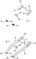
- Fig. 1 shows load line elements 100, 102, 104, 106, 108 of a core module 110 of a motorcycle rear swing arm 112.
- Fig. 2 shows load line elements 100, 102, 104, 106, 108 and load transfer elements 114, 116 of a core module 110 of a motorcycle rear wheel swing arm 112.
- Fig. 3 shows the core module 110 with the load line elements 100, 102, 104, 106, 108 and load transfer elements 114, 116, 118.
- Fig. 4 shows the motorcycle rear wheel swing arm 112 with the core module 110 and an encapsulation 120.
- FIGS. 5 and 6 show the motorcycle rear wheel swing arm 112 with the core module 110, the extrusion coating 120 and stiffening elements 122, 124.
- the invention is explained on the basis of one of the motorcycle rear wheel swing arm 112.
- the invention can also be used for other chassis components, for example a car control arm.
- the motorcycle rear wheel swing arm 112 has the core module 110 with the load line elements 100, 102, 104, 106, 108 and the load transfer elements 114, 116, 118.
- the motorcycle rear swing arm 112 has two of each other opposite swing ends 126, 128.
- the swing ends 126, 128 each have a fork-like shape.
- the load line elements 100, 102 are arranged on the swing end 126.
- the load line elements 100, 102 serve to accommodate a rotatable vehicle wheel.
- the load line elements 100, 102 each have on the outside a connection section for connection to a load transfer element 114, 116 and a slot-shaped hub section 130, 132 for receiving a bearing or an axle or shaft.
- the load line elements 100, 102 each have a cuboid shape.
- the load line elements 100, 102 each have a further functional section 134, 136 for fastening components, such as a brake.
- the load line elements 100, 102 are each made of a steel or aluminum alloy, designed in a lightweight construction with recesses and stiffening ribs and coated with a cathode dip.
- the load line elements 104, 106 are arranged on the swing end 128.
- the load line elements 104, 106 serve for the pivotable connection of the motorcycle rear wheel swing arm 112 to a vehicle frame.
- the load line elements 104, 106 each have on the outside a connection section for connection to a load transfer element 114, 116 and a hub section 138, 140 for receiving a bearing or an axle or shaft.
- the load line elements 104, 106 each have a sleeve-like shape.
- the load line elements 104, 106 are each made of a steel or aluminum alloy and are cathode-dip coated.
- the load line element 108 is arranged approximately centrally on the motorcycle rear wheel swing arm 112.
- the load line element 108 is used to pivot a suspension strut.
- the load line element 108 has on the outside a connection section for connection to the load transfer element 118 and hub sections, such as 142, for receiving a bearing or an axle or shaft.
- the load line element 108 is made of a steel or aluminum alloy and is cathode-dip coated.
- the load transfer element 114 has two transfer element ends and a course that follows a structural load path and is slightly curved several times.
- the transmission element ends of the load transmission element 114 are connected to the Load line elements 100, 104 connected in a load-transmitting manner.
- the load transfer element 116 has two transfer element ends and a course that follows a structural load path and is slightly curved several times.
- the transmission element ends of the load transmission element 116 are connected to the load line elements 102, 106 in a load-transmitting manner.
- the load transfer elements 114, 116 each have a UD carbon fiber band with unidirectionally arranged continuous fibers made of carbon, which are arranged at an angle of approximately 0 ° to a main load direction and extend between the load line elements 100, 104 and the load line elements 102, 106 .
- the carbon fibers are embedded in a plastic matrix made of PA6 or PA6.6.
- the load transfer elements 114, 116 are thus made from a fiber-plastic composite with a unidirectional fiber direction.
- the load transfer element 118 has an organic sheet with bidirectionally arranged continuous fibers made of carbon, which are arranged approximately at right angles to one another and each at an angle of approximately +/- 45 ° to a main load direction.
- the load transfer element 118 has a U-like shape and extends between the load line elements 100, 102 and the load line element 108.
- the carbon fibers are embedded in a plastic matrix made of PA6 or PA6.6.
- the load transfer element 118 is thus made from a fiber-plastic composite with a bidirectional fiber direction.
- the core module 110 is encapsulated with a fiber-filled plastic.
- the encapsulation 120 has a predetermined minimum proportion of recycled material.
- the encapsulation 120 has multidirectionally arranged short and / or long fibers made of carbon.
- the extrusion coating 120 largely surrounds the core module 110 and thus largely determines the geometry of the motorcycle rear wheel swing arm 112.
- the hub sections 130, 132, the functional sections 134, 136, the hub sections 138, 140 and the hub sections 142 remain accessible.
- sections of the load transfer elements 114, 116 initially remain free in order to enable them to be held during the overmolding.
- the encapsulation 120 is made of lightweight construction with recesses and stiffening ribs.
- the stiffening elements 122, 124 are arranged on the outside of the extrusion coating 120.
- the stiffening elements 122, 124 are designed like cladding.
- the stiffening elements 122, 124 are welded to the extrusion coating 120.
- the stiffening element 122 is arranged centrally on a lower outer side of the motorcycle rear wheel swing arm 112.
- Two stiffening elements, such as 124, are arranged on the side of the motorcycle rear wheel swing arm 112.
- the stiffening elements 122, 124 each have an organic sheet with bidirectionally arranged continuous fibers made of carbon, which are arranged approximately at right angles to one another and each at an angle of approximately +/- 45 ° to a main load direction.
- the carbon fibers are embedded in a plastic matrix made of PA6.6.
- the stiffening elements 122, 124 are thus made from a fiber-plastic composite with a bidirectional fiber direction.
- a critical load path is first identified between the load line elements 100, 102, 104, 106, 108, the critical load path is isolated and the load transfer elements 114, 116, 118 are modeled along the critical load path.
- the core module 110 is then first produced by joining the load line elements 100, 102, 104, 106, 108 and the load transfer elements 114, 116, 118.
- the core module 110 is then overmolded.
- the plastic matrix of the load transfer elements 114, 116, 118 and the extrusion coating 120 can have different melting temperatures.
- the load transfer elements 114, 116, 118 melt on the surface and a cohesive connection is created, so that phase separations and / or weld lines can be reduced or avoided.
- the stiffening elements 122, 124 are thermoplastically welded or glued.
Landscapes
- Engineering & Computer Science (AREA)
- Mechanical Engineering (AREA)
- Chemical & Material Sciences (AREA)
- Combustion & Propulsion (AREA)
- Transportation (AREA)
- Architecture (AREA)
- Structural Engineering (AREA)
- Manufacturing & Machinery (AREA)
- Vehicle Body Suspensions (AREA)
- Moulding By Coating Moulds (AREA)
- Injection Moulding Of Plastics Or The Like (AREA)
- Body Structure For Vehicles (AREA)
Description
- Die Erfindung betrifft eine Fahrwerkskomponente für ein Kraftfahrzeug. Außerdem betrifft die Erfindung ein Verfahren zum Herstellen einer derartigen Fahrwerkskomponente.
- Aus der
DE 10 2008 046 991 A1 ist ein lasttragendes Faserverbundstrukturbauteil bekannt, im Wesentlichen bestehend aus passgenau ineinandergreifenden, zwischen sich einen Hohlraum bildenden Einzelelementen aus Preformlingen aus geschichteten Faserhalbzeugen, wobei das Strukturbauteil eine komplexe, verzweigte Geometrie besitzt. Die Faserhalbzeuge basieren auf Kohlenstofffasern, Glasfasern, Multifasern, Aramidfasern und/oder Naturfasern. Die Fasern sind unidirektional, gekreuzt und/oder multiaxial im Faserhalbzeug angeordnet. Die Einzelelemente weisen ein U-Profil, einen monolithischen Rechtecksquerschnitt und ein I-Profil auf. In einem hinteren Abschnitt unterer Einzelelemente mit U-Profil sind Einleger in das Profil eingebracht, die einen Übergang von einer Hohlkastenstruktur zu einem monolithischen Lasteinleitungsbereich in einem hinteren Teil dienen. Ferner sind Deckel- und Stegeinsätze zur Versteifung der verzweigten Hohlkastenstruktur eingesetzt. - Außerdem ist aus der
DE 10 2008 046 991 A1 ein Verfahren bekannt zur integralen Herstellung eines lasttragenden, dickwandigen Faserverbundstrukturbauteils mit komplexer, verzweigter Geometrie in Hohlkastenbauweise durch Ausbilden von Einzelelementen des herzustellenden Strukturbauteils aus Preformlingen durch schichtweises Ablegen von Faserhalbzeugen auf der Geometrie des Strukturbauteils angepassten Preformwerkzeugen und Ausformen, derart, dass die Einzelelemente in ihrer Längserstreckung von drei Wänden begrenzt sind, die Einzelelemente monolithisch ausgebildet sind und die Einzelelemente ein I-Profil aufweisen, Bearbeitung der Einzelelemente zu deren passgenauem Ineinanderbringen, Ineinanderbringen der Einzelelemente in ein Harzinjektionswerkzeug, derart, dass zwischen den Einzelelementen Hohlräume gebildet werden, wobei in die Hohlräume entfernbare Stützkerne eingefügt werden, Schließen des Harzinjektionswerkzeugs und Injizieren und Aushärten eines Harzsystems unter Druck und erhöhter Temperatur zur Ausbildung des Faserverbundstrukturbauteils. - Aus der
DE 10 2011 085 029 A1 ist ein Stabilisator oder Stabilenker in Faserverbundbauweise bekannt, mit einteiligem Aufbau ohne Faserunterbrechung, wobei die Querschnittgeometrie, die Wandstärke sowie der Faserverlauf in axialer und radialer Richtung derart variieren, dass die aus dem zur Verfügung stehenden Bauraum und den zu erwartenden Belastungen resultierenden Anforderungen erfüllt sind. Der hauptsächlich torsionsbeanspruchte Mittelteil des Stabilisators weist einen weitestgehend kreisförmigen Querschnitt mit in axialer Richtung variierendem, der Belastung sowie der Position von Lasteinleitungselementen angepassten Durchmesser und Wandstärkenverlauf auf, die hauptsächlich biegebeanspruchten Endstücke des Stabilisators eine der Biegebelastung sowie der Anbindung der Radaufhängung und die Übergangsbereiche weisen eine der kombinierten Torsions- und Biegebelastung angepasste Querschnittform und Wandstärke auf. Zur Anpassung der Wandstärke an definierten Belastungsbereichen, insbesondere in Biegebereichen und an Lasteinleitungselementen, sind textile Einleger eingebracht und/oder ist die Faserablage verstärkt bzw. vermindert. - Außerdem ist aus der der
DE 10 2011 085 029 A1 ein Verfahren zur Herstellung eines derartigen Stabilisators oder Stabilenkers bekannt, umfassend folgende Schritte: auf einem geraden, elastischen sowie konturierten Kern durch die Ablage von Fasern, bevorzugt mittels Flechten oder Wickeln, ein Vorformling (Preform) erzeugt wird, dieser gemeinsam mit dem Kern in eine gebogene Geometrie umgeformt wird, in ein der gebogenen Geometrie entsprechend geformtes, geschlossenes Ur-/Umformwerkzeug eingelegt wird, in diesem die Fasern mit einem Matrixwerkstoff zu Laminat verbunden werden, dieses durch Einfüllung eines expandierenden Materials in den Kern in seine Endkontur verpresst wird und anschließend aus dem Ur-/Umformwerkzeug entnommen wird. - Aus der
DE 10 2013 002 585 A1 ist ein Fahrwerkslenker für ein Kraftfahrzeug bekannt umfassend mindestens zwei Lageraufnahmen für verschiedene Lagerungselemente und ein dazwischen angeordnetes Verbindungsbauteil aus faserverstärktem Kunststoff, das mit Klebeverbindungen an entsprechenden Wellenabsätzen der Lageraufnahmen befestigt ist, bei dem ein Innenraum des Verbindungsbauteiles durch die beiden Klebeverbindungen zwischen den Lageraufnahmen und dem Verbindungsbauteil luftdicht abgeschlossen ist, und dass in dem Innenraum ein Drucksensor zur Erfassung des Innendrucks in dem Innenraum angeordnet ist, der ein von dem Innendruck abhängiges Signal an eine Steuereinheit abgibt. - Außerdem ist aus der
DE 10 2013 002 585 A1 ein Verfahren bekannt zur Herstellung eines derartigen Fahrwerkslenkers umfassend: Bereitstellen von zwei Lageraufnahmen für verschiedene Lagerungselemente, Bereitstellen von einem Verbindungsbauteil aus faserverstärktem Kunststoff, Befestigen eines Drucksensors an einem Wellenabsatz von einem der Lageraufnahmen oder an dem Verbindungsbauteil in dessen Innenraum zur Erfassung des Innendrucks in dem Innenraum, Aufbringen eines Klebemittels an den Wellenabsätzen der Lageraufnahmen, Einlegen und Ausrichten der Lageraufnahmen und des Verbindungsbauteiles in einer Fertigungsvorrichtung, Ineinander Verbringen der Lageraufnahmen und des Verbindungsbauteiles durch die Fertigungsvorrichtung und Erzeugen von Klebeverbindungen zwischen dem Verbindungsbauteil und den Lageraufnamen, wodurch der Innenraum des Verbindungsbauteiles durch die beiden Klebeverbindungen zwischen den Lageraufnahmen und dem Verbindungsbauteil luftdicht abgeschlossen wird, und Überwachen des Innendrucks und Übertragen eines vom Innendruck abhängigen Signals in bzw. an einer Steuereinheit. - Das Dokument
US 2004/0045762 A1 betrifft eine gattungsgemäße Halterung einer aus Verbundwerkstoffen hergestellten Kraftverbindungsstrebe für ein Fahrgestell eines Kraftfahrzeugs. Die Halterung aus dem DokumentUS 2004/0045762 A1 wird vorzugsweise in Verbindung mit Achsstreben oder Querlenkern des Fahrgestells verwendet. Dem DokumentUS 2004/0045762 A1 zufolge weist die Kraftanschlussstrebe einen Grundkörper mit einem Metalleinsatz auf. Eine Kunststoffstruktur bildet eine Befestigung für eine Hülse im Bereich einer Montagehalterung. Die Montagehalterung wird durch eine Hülse gebildet wird. Die Kunststoffstruktur ist als Extrusionsbeschichtung des Metalleinsatz und der Hülse hergestellt. Das DokumentUS 2004/0045762 A1 offenbart eine Ausführung mit einem H-förmigen Kunststoffprofil mit einem U-förmigen Metalleinsatz. An einem linken oberen und unteren Schenkel des H-Profils sind Öffnungen und zwei in die Öffnungen eingeführte Hülsen vorgesehen, die sich axial gegenüberliegen. Die obere und die untere Hülse bilden zusammenwirkend eine einzige Montagehalterung. Auf die Mitteilung nach Regel 161 (1) und 162 EPÜ - Aus Dokument
WO 2014/019787 A1 ist eine Strebe, insbesondere für ein Fahrwerk eines Kraftfahrzeugs, bekannt, die als Kräfte übertragende Verbindung zwischen zwei Lagerstellen dient, wobei die Strebe zumindest teilweise mit Organoblech ausgeführt ist, wobei das Organoblech einen Strukturkörper bildet, welcher durch an- oder eingespritzten Kunststoff verstärkt oder ergänzt ist. Das DokumentWO 2014/019787 A1 offenbart Ausführungen der Strebe mit einem eingepressten ersten Lager und ohne Lager. - Aus dem Dokument
DE 101 53 799 A1 ist eine Kraftverbindungsstrebe eines Fahrwerks eines Personen- oder Nutzkraftwagens bekannt zur Verbindung zwischen einem Chassis und einem Radträger, vorzugsweise Achsstrebe oder Fahrwerkslenker, mit einem länglichen Grundkörper und mindestens zwei endständigen Lageraufnahmen zur Ein- und Ausleitung von Kräften, bei der der Grundkörper einen Verbund mindestens einer flachen Metalleinlage und einer die Restkontur bildenden Kunststoffstruktur aufweist, welche durch zumindest teilweises Umspritzen der Metalleinlage gebildet ist. - Das Dokument
DE 10 2013 007 284 A1 betrifft eine Verbindungsstrebe, die an einem Fahrzeug als Fahrwerkbauteil, insbesondere Lenker, als Stabilisator, insbesondere Wankstabilisator, als Stütze, insbesondere Pendelstütze zur Abstützung eines Antriebsaggregats oder dgl. mehr verwendbar ist. Dem DokumentDE 10 2013 007 284 A1 zufolge ist die Grundstruktur der Verbindungsstrebe durch eine Mehrzahl von Prepregs gebildet, die zu ersten und zweiten Prepreg-Windungslagen geformt sind. Die Verbindungsstrebe weist einen langgestreckten Abschnitt respektive Stangenabschnitt und beidenends desselben je ein Lagerauge auf. Die Lageraugen sind jeweils durch mehrere umlaufende erste Prepreg-Windungslagen gebildet. Des Weiteren sind mehrere von einem zum anderen Lagerauge über einen Teilkreis derselben geführte zweite Prepreg-Windungslagen vorgesehen, die zur Ausbildung des Stangenabschnitts besagte Lageraugen untereinander verbinden. In einem in Längsrichtung der Verbindungsstrebe gesehen mittleren Bereich des Stangenabschnitts gegenüberliegend verlaufende Windungsabschnitte der zweiten Prepreg-Windungslagen sind mittelbar über Prepreg-Zwischenlagen aufeinander gelegt und streben dann zur Kraftumleitung und Vermeidung von Spannungsspitzen zu den Lageraugen hin keilförmig auseinander, wodurch jeweils ein Entlastungsloch ausgebildet wird, um dann über einen Teilkreis des Lagerauges um dasselbe herumgeführt zu werden. Gemäß einem Ausführungsbeispiel bestehen die Prepreg-Windungslagen und die Prepreg-Zwischenlagen aus einer unidirektionalen Schicht eines Faser-Kunststoffverbundes, in welcher alle Fasern in eine einzige Richtung in Umlaufrichtung der Prepreg-Windungslagen bzw. bezüglich eines überwiegenden Teils der Prepreg-Zwischenlagen in Längsrichtung der Verbindungsstrebe orientiert sind. - Der Erfindung liegt die Aufgabe zugrunde, eine eingangs genannte Fahrwerkskomponente baulich und/oder funktional zu verbessern. Außerdem liegt der Erfindung die Aufgabe zugrunde, ein eingangs genanntes Verfahren zu verbessern.
- Die Aufgabe wird gelöst mit einer Fahrwerkskomponente mit den Merkmalen des Anspruchs 1. Außerdem wird die Aufgabe gelöst mit einem Verfahren mit den Merkmalen des Anspruchs 9. Vorteilhafte Ausführungen und Weiterbildungen sind Gegenstand der Unteransprüche.
- Das Kraftfahrzeug kann ein Kraftrad sein. Das Kraftfahrzeug kann ein PKW sein. Die Fahrwerkskomponente kann eine Hinterradschwinge sein. Die Fahrwerkskomponente kann ein Querlenker sein. Die Fahrwerkskomponente kann eine stangenartige Form aufweisen. Die Fahrwerkskomponente kann eine gabelartige Form aufweisen. Die Fahrwerkskomponente kann ein erstes Komponentenende und ein dem ersten Komponentenende gegenüberliegendes zweites Komponentenende aufweisen. Das erste Komponentenende und/oder das zweite Komponentenende können/kann eine fortsatzartige Form aufweisen. Das erste Komponentenende und/oder das zweite Komponentenende können/kann eine gabelartige Form aufweisen.
- Das Kernmodul kann eine gesondert herstellbare Baugruppe bilden. Das Kernmodul kann skelettartig ausgeführt sein. Das Kernmodul kann flexibel sein.
- Das wenigstens eine erste Lastleitungselement und/oder das wenigstens eine zweite Lastleitungselement können/kann einen Verbindungsabschnitt zur Verbindung mit dem Lastübertragungselement aufweisen. Der Verbindungsabschnitt kann eine Oberfläche mit einer erhöhten Rauheit aufweisen. Der Verbindungsabschnitt kann eine gerändelte Oberfläche aufweisen. Der Verbindungsabschnitt kann wenigstens einen Hinterschnitt aufweisen. Das wenigstens eine erste Lastleitungselement und/oder das wenigstens eine zweite Lastleitungselement können/kann einen Nabenabschnitt aufweisen. Der Nabenabschnitt kann zur Aufnahme eines Lagers dienen. Der Nabenabschnitt kann zur Aufnahme einer Achse oder Welle dienen.
- Das wenigstens eine erste Lastleitungselement und/oder das wenigstens eine zweite Lastleitungselement können/kann eine quaderartige Form aufweisen. Das wenigstens eine erste Lastleitungselement und/oder das wenigstens eine zweite Lastleitungselement können/kann eine hülsenartige Form aufweisen.
- Das wenigstens eine erste Lastleitungselement und/oder das wenigstens eine zweite Lastleitungselement können/kann aus einem Metall hergestellt sein. Das Metall kann eine Stahl- oder Aluminiumlegierung sein. Das wenigstens eine erste Lastleitungselement und/oder das wenigstens eine zweite Lastleitungselement können/kann zumindest abschnittsweise lackiert sein. Das wenigstens eine erste Lastleitungselement und/oder das wenigstens eine zweite Lastleitungselement können/kann zumindest abschnittsweise beschichtet sein. Das wenigstens eine erste Lastleitungselement und/oder das wenigstens eine zweite Lastleitungselement können/kann elektrophoretisch tauchlackiert sein.
- Das wenigstens eine erste Lastleitungselement und/oder das wenigstens eine zweite Lastleitungselement können/kann zumindest einen weiteren Funktionsabschnitt aufweisen. Der wenigstens eine weitere Funktionsabschnitt kann zur Befestigung von Bauteilen an der Fahrwerkskomponente dienen.
- Das wenigstens eine erste Lastleitungselement und/oder das wenigstens eine zweite Lastleitungselement können/kann an unterschiedlichen Komponentenenden angeordnet sein. Das wenigstens eine erste Lastleitungselement und/oder das wenigstens eine zweite Lastleitungselement können/kann an demselben Komponentenende angeordnet sein.
- Das wenigstens eine Lastübertragungselement kann ein erstes Übertragungselementende und ein dem ersten Übertragungselementende gegenüberliegendes zweites Übertragungselementende aufweisen. Das erste Übertragungselementende kann mit dem wenigstens einen ersten Lastleitungselement lastübertragend verbunden sein. Das zweite Übertragungselementende kann mit dem wenigstens einen zweiten Lastleitungselement lastübertragend verbunden sein.
- Das wenigstens eine Lastübertragungselement kann Fasern aufweisen. Die Fasern können organische Fasern, wie Aramidfasern, Kohlenstofffasern, Polyester-Fasern, Nylon-Fasern, Polyethylen-Fasern, Plexiglas-Fasern, und/oder anorganische Fasern, wie Basaltfasern, Borfasern, Glasfasern, Keramikfasern, Kieselsäurefasern, sein.
- Das wenigstens eine Lastübertragungselement kann unidirektional angeordnete Endlosfasern aufweisen. Die unidirektional angeordneten Endlosfasern können mit einem Winkel von zumindest annähernd 0° zu einem Hauptlastrichtungsverlauf angeordnet sein. Die unidirektional angeordneten Endlosfasern können sich zwischen dem wenigstens einen ersten Lastleitungselement und dem wenigstens einen zweiten Lastleitungselement erstrecken. Das wenigstens eine Lastübertragungselement kann ein UD-Kohlenstofffaser-Band aufweisen.
- Das wenigstens eine Lastübertragungselement kann bi- oder multidirektional angeordnete Endlosfasern aufweisen. Bidirektional angeordnete Endlosfasern können zumindest annähernd rechtwinklig zueinander angeordnet sein. Bidirektional angeordnete Endlosfasern können mit einem Winkel von zumindest annähernd +/-45° zu einem Hauptlastrichtungsverlauf angeordnet sein. Das wenigstens eine Lastübertragungselement kann eine verkleidungsartige Form aufweisen. Das wenigstens eine Lastübertragungselement kann eine plattenartige Form aufweisen. Das wenigstens eine Lastübertragungselement kann ein Organoblech aufweisen.
- Die Fasern können in ein Matrixmaterial eingebettet sein. Das Matrixmaterial kann thermoplastisch sein. Das Matrixmaterial kann Polyamid, insbesondere PA 6 oder PA6.6, sein. Das Matrixmaterial kann Polypropylen sein Das Matrixmaterial kann duroplastisch sein.
- Das wenigstens eine Lastübertragungselement kann ein Metall aufweisen. Das Metall kann eine Stahl- oder Aluminiumlegierung sein. Das wenigstens eine Lastübertragungselement kann ein Rundprofil, I-Profil oder T-Profil aufweisen. Das wenigstens eine Lastübertragungselement kann ein Hohlprofil aufweisen. Das wenigstens eine Lastübertragungselement kann vorgeformt sein. Das wenigstens eine Lastübertragungselement kann eine gebogene Form aufweisen.
- Die Umspritzung kann einen fasergefüllten Kunststoff mit einem vorgegebenen Mindestanteil an Recycling- bzw. Sekundärmaterial aus Verschnittresten aufweisen. Die Umspritzung kann Kurz- und/oder Langfasern aufweisen. Die Fasern können organische Fasern, wie Aramidfasern, Kohlenstofffasern, Polyester-Fasern, Nylon-Fasern, Polyethylen-Fasern, Plexiglas-Fasern, und/oder anorganische Fasern, wie Basaltfasern, Borfasern, Glasfasern, Keramikfasern, Kieselsäurefasern, sein. Die Umspritzung kann einen thermoplastischen Kunststoff aufweisen. Die Umspritzung kann Polyamid, insbesondere PA6.6, aufweisen. Die Umspritzung bzw. Umpressung kann einen duroplastischen Kunststoff aufweisen. Die Umspritzung kann Ausnehmungen aufweisen. Die Umspritzung kann Versteifungsrippen aufweisen.
- Die Fahrwerkskomponente kann wenigstens ein außenseitig an der Umspritzung angeordnetes Versteifungselement aufweist. Das wenigstens eine Versteifungselement kann bi- oder multidirektional angeordnete Endlosfasern aufweisen. Die Fasern können organische Fasern, wie Aramidfasern, Kohlenstofffasern, Polyester-Fasern, Nylon-Fasern, Polyethylen-Fasern, Plexiglas-Fasern, und/oder anorganische Fasern, wie Basaltfasern, Borfasern, Glasfasern, Keramikfasern, Kieselsäurefasern, sein. Bidirektional angeordnete Endlosfasern können zumindest annähernd rechtwinklig zueinander angeordnet sein. Bidirektional angeordnete Endlosfasern können mit einem Winkel von zumindest annähernd +/-45° zu einem Hauptlastrichtungsverlauf angeordnet sein. Das wenigstens eine Versteifungselement kann eine verkleidungsartige Form aufweisen. Das wenigstens eine Versteifungselement kann eine plattenartige Form aufweisen. Das wenigstens eine Versteifungselement kann ein Organoblech aufweisen.
- Zur Herstellung der Fahrwerkskomponente kann zunächst ein kritischer Lastpfad identifiziert werden. Der kritische Lastpfad kann isoliert werden. Das wenigstens eine Lastübertragungselement kann entlang des kritischen Lastpfads modelliert werden. Ein Umspritzen des Kernmoduls kann simuliert werden. Eine Angussanordnung kann bestimmt werden. Die Identifizierung, die Isolierung, die Modellierung, das Umspritzen und/oder die Angussanordnung können/kann mithilfe eines Computerprogramms erfolgen/bestimmt werden.
- Das wenigstens eine erste Lastleitungselement, das wenigstens eine Lastübertragungselement und das wenigstens eine zweite Lastleitungselement können miteinander zur Herstellung des Kernmoduls kraftschlüssig, formschlüssig und/oder stoffschlüssig gefügt werden. Beim nachfolgenden Umspritzen des Kernmoduls kann mithilfe der Umspritzung eine weitere belastungsfähige Verbindung zwischen dem wenigstens einen ersten Lastleitungselement, dem wenigstens einen Lastübertragungselement und dem wenigstens einen zweiten Lastleitungselement erfolgen. Das wenigstens eine Lastübertragungselement kann vollständig umspritzt werden. Das wenigstens eine Lastübertragungselement kann teilweise umspritzt werden, um ein Halten des Lastübertragungselements während des Umspritzens zu ermöglichen.
- Das wenigstens eine Lastübertragungselement und/oder das wenigstens eine Versteifungselement können/kann aus einem vorimprägnierten Faserhalbzeug hergestellt werden. Das wenigstens eine Lastübertragungselement kann aus einem trockenen Faserhalbzeug hergestellt und beim Umspritzen infiltriert werden.
- Nachfolgend können die Umspritzung und das wenigstens eine Versteifungselement gefügt werden. Das wenigstens eine Versteifungselement kann aus einem vorimprägnierten Faserhalbzeug hergestellt und beim Umspritzen infiltriert werden. Das wenigstens eine Versteifungselement kann zunächst gesondert hergestellt und nachfolgend mit der Umspritzung gefügt werden. Die Umspritzung und das wenigstens eine Versteifungselement können miteinander kraftschlüssig, formschlüssig und/oder stoffschlüssig gefügt werden. Die Umspritzung und das wenigstens eine Versteifungselement können miteinander verschweißt werden. Die Umspritzung und das wenigstens eine Versteifungselement können miteinander in einem umlaufenden Randbereich verschweißt werden. Die Umspritzung und das wenigstens eine Versteifungselement können miteinander an Versteifungsrippen des wenigstens einen Versteifungselements verschweißt werden.
- Mit der Erfindung kann eine CFRTP-Bauweise dem Fahrwerksbereich zugänglich gemacht werden. Eine CFRTP-Bauweise ist eine Bauweise mit karbonfaserverstärkten thermoplastischen Kunststoffen (Englisch: carbon fiber reinforced thermoplastic, CFRTP). Im Fahrzeugbau etablierte Kunststoffe sind einsetzbar. Ein Gewicht wird reduziert. Ein Aufwand, wie Kostenaufwand, wird reduziert. Eine Nachhaltigkeit wird erhöht.
- Nachfolgend werden Ausführungsbeispiele der Erfindung unter Bezugnahme auf Figuren näher beschrieben. Aus dieser Beschreibung ergeben sich weitere Merkmale und Vorteile.
- Es zeigen schematisch und beispielhaft:
- Fig. 1
- Lastleitungelemente eines Kernmoduls einer Motorradhinterradschwinge,
- Fig. 2
- Lastleitungelemente und Lastübertragungselemente eines Kernmoduls einer Motorradhinterradschwinge,
- Fig. 3
- ein Kernmodul einer Motorradhinterradschwinge mit Lastleitungelementen und Lastübertragungselementen,
- Fig. 4
- eine Motorradhinterradschwinge mit einem Kernmodul und einer Umspritzung,
- Fig. 5
- eine Motorradhinterradschwinge mit einem Kernmodul, einer Umspritzung und Versteifungselementen und
- Fig. 6
- eine Motorradhinterradschwinge mit einem Kernmodul, einer Umspritzung und Versteifungselementen.
-
Fig. 1 zeigt Lastleitungelemente 100, 102, 104, 106, 108 eines Kernmoduls 110 einer Motorradhinterradschwinge 112.Fig. 2 zeigt Lastleitungelemente 100, 102, 104, 106, 108 und Lastübertragungselemente 114, 116 eines Kernmoduls 110 einer Motorradhinterradschwinge 112.Fig. 3 zeigt das Kernmodul 110 mit den Lastleitungelementen 100, 102, 104, 106, 108 und Lastübertragungselementen 114, 116, 118.Fig. 4 zeigt die Motorradhinterradschwinge 112 mit dem Kernmodul 110 und einer Umspritzung 120.Fig. 5 und Fig. 6 zeigen die Motorradhinterradschwinge 112 mit dem Kernmodul 110, der Umspritzung 120 und Versteifungselementen 122, 124. - Vorliegend wird die Erfindung anhand einer der Motorradhinterradschwinge 112 erläutert. Die Erfindung kann jedoch auch für andere Fahrwerkskomponenten, beispielsweise einen PKW-Querlenker, genutzt werden.
- Die Motorradhinterradschwinge 112 weist das Kernmodul 110 mit den Lastleitungelementen 100, 102, 104, 106, 108 und den Lastübertragungselementen 114, 116, 118 auf. Die Motorradhinterradschwinge 112 weist zwei einander gegenüberliegende Schwingenenden 126, 128 auf. Die Schwingenenden 126, 128 weisen jeweils eine gabelartige Form auf.
- Die Lastleitungelemente 100, 102 sind an dem Schwingenende 126 angeordnet. Die Lastleitungelemente 100, 102 dienen zur Aufnahme eines drehbaren Fahrzeugrads. Die Lastleitungelemente 100, 102 weisen jeweils außenseitig einen Verbindungsabschnitt zur Verbindung mit einem Lastübertragungselement 114, 116 und einen langlochförmigen Nabenabschnitt 130, 132 zur Aufnahme eines Lagers bzw. einer Achse oder Welle auf. Die Lastleitungelemente 100, 102 weisen jeweils eine quaderartige Form auf. Die Lastleitungelemente 100, 102 weisen jeweils einen weiteren Funktionsabschnitt 134, 136 zur Befestigung von Bauteilen, wie einer Bremse, auf. Die Lastleitungelemente 100, 102 sind jeweils aus einer Stahl- oder Aluminiumlegierung hergestellt, in Leichtbauweise mit Ausnehmungen und Versteifungsrippen ausgeführt und kathodentauchlackiert.
- Die Lastleitungelemente 104, 106 sind an dem Schwingenende 128 angeordnet. Die Lastleitungelemente 104, 106 dienen zur schwenkbaren Verbindung der Motorradhinterradschwinge 112 mit einem Fahrzeugrahmen. Die Lastleitungelemente 104, 106 weisen jeweils außenseitig einen Verbindungsabschnitt zur Verbindung mit einem Lastübertragungselement 114, 116 und einen Nabenabschnitt 138, 140 zur Aufnahme eines Lagers bzw. einer Achse oder Welle auf. Die Lastleitungelemente 104, 106 weisen jeweils eine hülsenartige Form auf. Die Lastleitungelemente 104, 106 sind jeweils aus einer Stahl- oder Aluminiumlegierung hergestellt und kathodentauchlackiert.
- Das Lastleitungelement 108 ist an der Motorradhinterradschwinge 112 in etwa mittig angeordnet. Das Lastleitungelement 108 dient zur schwenkbaren Aufnahme eines Federbeins. Das Lastleitungelement 108 weist außenseitig einen Verbindungsabschnitt zur Verbindung mit dem Lastübertragungselement 118 und Nabenabschnitte, wie 142, zur Aufnahme eines Lagers bzw. einer Achse oder Welle auf. Das Lastleitungelement 108 ist aus einer Stahl- oder Aluminiumlegierung hergestellt und kathodentauchlackiert.
- Das Lastübertragungselement 114 weist zwei Übertragungselementenden und einen einem strukturellen Lastpfad folgenden mehrfach leicht geschwungenen Verlauf auf. Die Übertragungselementenden des Lastübertragungselements 114 sind mit den Lastleitungelementen 100, 104 lastübertragend verbunden. Das Lastübertragungselement 116 weist zwei Übertragungselementende und einen einem strukturellen Lastpfad folgenden mehrfach leicht geschwungenen Verlauf auf. Die Übertragungselementenden des Lastübertragungselements 116 sind mit den Lastleitungelementen 102, 106 lastübertragend verbunden.
- Die Lastübertragungselemente 114, 116 weisen jeweils ein UD-Kohlenstofffaser-Band mit unidirektional angeordnete Endlosfasern aus Kohlenstoff auf, die mit einem Winkel von etwa 0° zu einem Hauptlastrichtungsverlauf angeordnet sind und sich zwischen den Lastleitungselementen 100, 104 bzw. den Lastleitungselementen 102, 106 erstrecken. Die Kohlenstofffasern sind in einer Kunststoffmatrix aus PA6 oder PA6.6 eingebettet. Die Lastübertragungselemente 114, 116 sind somit aus einem Faser-Kunststoff-Verbund mit unidirektionaler Faserrichtung hergestellt.
- Das Lastübertragungselement 118 weist ein Organoblech mit bidirektional angeordneten Endlosfasern aus Kohlenstoff auf, die zueinander in etwa rechtwinklig und jeweils mit einem Winkel von etwa +/-45° zu einem Hauptlastrichtungsverlauf angeordnet sind. Das Lastübertragungselement 118 weist eine U-artige Form auf und erstreckt sich zwischen den Lastleitungselementen 100, 102 und dem Lastleitungselement 108. Die Kohlenstofffasern sind in einer Kunststoffmatrix aus PA6 oder PA6.6 eingebettet. Das Lastübertragungselement 118 ist somit aus einem Faser-Kunststoff-Verbund mit bidirektionaler Faserrichtung hergestellt.
- Das Kernmodul 110 ist mit einem fasergefüllten Kunststoff umspritzt. Die Umspritzung 120 weist einen vorgegebenen Mindestanteil an Recyclingmaterial auf. Die Umspritzung 120 weist multidirektional angeordnete Kurz- und/oder Langfasern aus Kohlenstoff auf. Die Umspritzung 120 umschließt das Kernmodul 110 weitgehend und bestimmt damit maßgeblich die Geometrie der Motorradhinterradschwinge 112. Die Nabenabschnitte 130, 132, die Funktionsabschnitte 134, 136, die Nabenabschnitte 138, 140 und die Nabenabschnitte 142 bleiben zugänglich. Ebenso bleiben Abschnitte der Lastübertragungselemente 114, 116 zunächst frei, um ein Halten während des Umspritzens zu ermöglichen. Die Umspritzung 120 ist in Leichtbauweise mit Ausnehmungen und Versteifungsrippen ausgeführt.
- Die Versteifungselemente 122, 124 sind außenseitig an der Umspritzung 120 angeordnet. Die Versteifungselemente 122, 124 sind verkleidungsartig ausgeführt. Die Versteifungselemente 122, 124 sind mit der Umspritzung 120 verschweißt. Das Versteifungselement 122 ist mittig an einer unteren Außenseite der Motorradhinterradschwinge 112 angeordnet. Zwei Versteifungselemente, wie 124, sind seitlich an der Motorradhinterradschwinge 112 angeordnet.
- Die Versteifungselemente 122, 124 weisen jeweils ein Organoblech mit bidirektional angeordneten Endlosfasern aus Kohlenstoff auf, die zueinander in etwa rechtwinklig und jeweils mit einem Winkel von etwa +/-45° zu einem Hauptlastrichtungsverlauf angeordnet sind. Die Kohlenstofffasern sind in einer Kunststoffmatrix aus PA6.6 eingebettet. Die Versteifungselemente 122, 124 sind somit aus einem Faser-Kunststoff-Verbund mit bidirektionaler Faserrichtung hergestellt.
- Zur Herstellung der Motorradhinterradschwinge 112 wird zunächst zwischen den Lastleitungselementen 100, 102, 104, 106, 108 ein kritischer Lastpfad identifiziert, der kritische Lastpfad wird isoliert und die Lastübertragungselemente 114, 116, 118 werden entlang des kritischen Lastpfads modelliert. Daraufhin wird zunächst das Kernmodul 110 durch Fügen der Lastleitungselemente 100, 102, 104, 106, 108 und der Lastübertragungselemente 114, 116, 118 hergestellt. Nachfolgend wird das Kernmodul 110 umspritzt. Die Kunststoffmatrix der Lastübertragungselemente 114, 116, 118 und die Umspritzung 120 können unterschiedliche Schmelztemperaturen aufweisen. Beim Umspritzen schmelzen die Lastübertragungselemente 114, 116, 118 oberflächlich auf und es entsteht eine stoffschlüssige Verbindung, sodass Phasentrennungen und/oder Bindenähte reduziert oder vermieden werden können. Abschließend werden die Versteifungselemente 122, 124 thermoplastisch verschweißt bzw. verklebt.
-
- 100
- Lastleitungelement
- 102
- Lastleitungelement
- 104
- Lastleitungelement
- 106
- Lastleitungelement
- 108
- Lastleitungelement
- 110
- Kernmodul
- 112
- Fahrwerkskomponente, Motorradhinterradschwinge
- 114
- Lastübertragungselement
- 116
- Lastübertragungselement
- 118
- Lastübertragungselement
- 120
- Umspritzung
- 122
- Versteifungselement
- 124
- Versteifungselement
- 126
- Schwingenende
- 128
- Schwingenende
- 130
- Nabenabschnitt
- 132
- Nabenabschnitt
- 134
- Funktionsabschnitt
- 136
- Funktionsabschnitt
- 138
- Nabenabschnitt
- 140
- Nabenabschnitt
- 142
- Nabenabschnitt
Claims (10)
- Fahrwerkskomponente (112) für ein Kraftfahrzeug, die Fahrwerkskomponente (112) aufweisend ein Kernmodul (110) mit wenigstens einem ersten Lastleitungselement (100, 102), wenigstens einem zweiten Lastleitungselement (104, 106) und wenigstens einem das wenigstens eine erste Lastleitungselement (100, 102) und das wenigstens eine zweite Lastleitungselement (104, 106) verbindenden Lastübertragungselement (114, 116, 118) und eine Umspritzung (120), dadurch gekennzeichnet, dass wenigstens ein Lastübertragungselement (114, 116) unidirektional angeordnete Endlosfasern und wenigstens ein Lastübertragungselement (118) bi- oder multidirektional angeordnete Endlosfasern aufweist.
- Fahrwerkskomponente (112) nach Anspruch 1, dadurch gekennzeichnet, dass das wenigstens eine Lastübertragungselement (114, 116) ein Unidirektional-Kohlenstofffaser-Band aufweist.
- Fahrwerkskomponente (112) nach wenigstens einem der vorhergehenden Ansprüche, dadurch gekennzeichnet, dass das wenigstens eine Lastübertragungselement (118) ein Organoblech aufweist.
- Fahrwerkskomponente nach wenigstens einem der vorhergehenden Ansprüche, dadurch gekennzeichnet, dass das wenigstens eine Lastübertragungselement ein Metall aufweist.
- Fahrwerkskomponente (112) nach wenigstens einem der vorhergehenden Ansprüche, dadurch gekennzeichnet, dass die Umspritzung (120) einen fasergefüllten Kunststoff mit einem vorgegebenen Mindestanteil an Recyclingmaterial aufweist.
- Fahrwerkskomponente (112) nach wenigstens einem der vorhergehenden Ansprüche, dadurch gekennzeichnet, dass die Fahrwerkskomponente (112) wenigstens ein außenseitig an der Umspritzung (120) angeordnetes Versteifungselement (122, 124) aufweist.
Auf die Mitteilung nach Regel 161 (1) und 162 EPÜ - Fahrwerkskomponente (112) nach wenigstens einem der vorhergehenden Ansprüche, dadurch gekennzeichnet, dass das wenigstens eine Versteifungselement (122, 124) bi- oder multidirektional angeordnete Endlosfasern aufweist.
- Fahrwerkskomponente (112) nach wenigstens einem der vorhergehenden Ansprüche, dadurch gekennzeichnet, dass das wenigstens eine Versteifungselement (122, 124) ein Organoblech aufweist.
- Verfahren zum Herstellen einer Fahrwerkskomponente (112) nach wenigstens einem der vorhergehenden Ansprüche, dadurch gekennzeichnet, dass zunächst das Kernmodul (110) durch Fügen des wenigstens einen ersten Lastleitungselements (100, 102) und des wenigstens einen Lastübertragungselements (114, 116, 118) sowie des wenigstens einen Lastübertragungselements (114, 116, 118) und des wenigstens einen zweiten Lastleitungselements (104, 106) hergestellt und nachfolgend das Kernmodul (110) umspritzt wird.
- Verfahren nach Anspruch 9, dadurch gekennzeichnet, dass nachfolgend die Umspritzung (120) und das wenigstens eine Versteifungselement (122, 124) gefügt werden.
Applications Claiming Priority (2)
| Application Number | Priority Date | Filing Date | Title |
|---|---|---|---|
| DE102017204464.0A DE102017204464A1 (de) | 2017-03-17 | 2017-03-17 | Fahrwerkskomponente für ein Kraftfahrzeug und Verfahren zum Herstellen einer Fahrwerkskomponente |
| PCT/EP2018/052067 WO2018166691A1 (de) | 2017-03-17 | 2018-01-29 | Fahrwerkskomponente für ein kraftfahrzeug und verfahren zum herstellen einer fahrwerkskomponente |
Publications (2)
| Publication Number | Publication Date |
|---|---|
| EP3595918A1 EP3595918A1 (de) | 2020-01-22 |
| EP3595918B1 true EP3595918B1 (de) | 2021-04-07 |
Family
ID=61198806
Family Applications (1)
| Application Number | Title | Priority Date | Filing Date |
|---|---|---|---|
| EP18704894.7A Active EP3595918B1 (de) | 2017-03-17 | 2018-01-29 | Fahrwerkskomponente für ein kraftfahrzeug und verfahren zum herstellen einer fahrwerkskomponente |
Country Status (5)
| Country | Link |
|---|---|
| US (1) | US11014610B2 (de) |
| EP (1) | EP3595918B1 (de) |
| CN (1) | CN110114232B (de) |
| DE (1) | DE102017204464A1 (de) |
| WO (1) | WO2018166691A1 (de) |
Families Citing this family (10)
| Publication number | Priority date | Publication date | Assignee | Title |
|---|---|---|---|---|
| JP2018122642A (ja) * | 2017-01-30 | 2018-08-09 | スズキ株式会社 | スイングアーム |
| DE102019106937B4 (de) * | 2019-03-19 | 2025-03-27 | Benteler Automobiltechnik Gmbh | Mehrschenkliger Lenker für eine Radaufhängung in einem Fahrzeug |
| FI128515B (en) * | 2019-04-11 | 2020-06-30 | Pole Bicycle Company Oy | Arrangements for a bicycle frame and manufacturing process |
| DE102019206435A1 (de) * | 2019-05-06 | 2020-11-12 | Schäfer MWN GmbH | Mehrpunktlenker für ein Fahrwerk eines Fahrzeugs |
| DE102019206436A1 (de) * | 2019-05-06 | 2020-11-12 | Schäfer MWN GmbH | Mehrpunktlenker für ein Fahrwerk eines Fahrzeugs |
| EP3936354B1 (de) | 2020-07-08 | 2023-08-30 | Autotech Engineering S.L. | Chassis-bauteil für ein kraftfahrzeug |
| IT202000021133A1 (it) * | 2020-09-07 | 2022-03-07 | Marelli Suspension Systems Italy S P A | Metodo di fabbricazione di un componente strutturale di un autoveicolo a sezione cava in materiale composito, in particolare un braccio per sospensione, e braccio per sospensione ottenuto mediante il metodo |
| CN113212088A (zh) * | 2021-05-25 | 2021-08-06 | 东风柳州汽车有限公司 | 一种弹簧摆臂总成 |
| US12497119B2 (en) * | 2021-12-15 | 2025-12-16 | Bryce Barsnick | Motorbike swingarm cover |
| US20240017789A1 (en) * | 2022-07-14 | 2024-01-18 | Zero Motorcycles, Inc. | Swingarm assembly, vehicle including a swingarm assembly, and method of manufacturing a swingarm assembly |
Family Cites Families (25)
| Publication number | Priority date | Publication date | Assignee | Title |
|---|---|---|---|---|
| JPS6029787U (ja) * | 1983-08-04 | 1985-02-28 | 本田技研工業株式会社 | 自動二輪車用リヤフォ−ク |
| US4841801A (en) * | 1987-03-25 | 1989-06-27 | Trw Inc. | Connecting rod |
| US4992313A (en) * | 1987-12-14 | 1991-02-12 | Shobert James P | Fiber-reinforced plastic strut connecting link |
| US4947017A (en) * | 1989-04-03 | 1990-08-07 | General Motors Corporation | Composite weld gun and method of making same |
| US5406033A (en) * | 1992-09-02 | 1995-04-11 | Maclean-Fogg Company | Insulator structure and method of construction |
| FR2705610B1 (fr) * | 1993-05-26 | 1995-08-11 | Aerospatiale | Procédé de fabrication de bielle en matériau composite monobloc par mise en place de fibres pré-imprégnées sur un mandrin extractible et bielle ainsi obtenue. |
| US5885688A (en) * | 1996-12-26 | 1999-03-23 | The Pullman Company | Steel reinforced filled polymer torque rod |
| US6324940B1 (en) * | 1997-08-13 | 2001-12-04 | Maclean-Fogg Company | Composite link |
| DE10153799A1 (de) * | 2001-11-05 | 2003-05-15 | Zf Lemfoerder Metallwaren Ag | Kraftverbindungsstrebe |
| DE10154210A1 (de) * | 2001-11-07 | 2003-05-15 | Zf Lemfoerder Metallwaren Ag | Lageraufnahme einer aus Verbundwerkstoffen hergestellten Kraftverbindungsstrebe |
| DE102008046991A1 (de) | 2008-09-12 | 2010-03-25 | Mt Aerospace Ag | Lasttragendes dickwandiges Faserverbundstrukturbauteil und Verfahren zu dessen Herstellung |
| DE102011085029A1 (de) | 2011-10-21 | 2013-04-25 | Luhn & Pulvermacher - Dittmann & Neuhaus GmbH | Stabilisator in Faserkunststoffverbund und Verfahren zu dessen Herstellung |
| DE102011086890A1 (de) * | 2011-11-22 | 2013-05-23 | Bayerische Motoren Werke Aktiengesellschaft | Bauelement im Fahrwerk eines Kraftfahrzeugs |
| EP2689943B1 (de) * | 2012-07-27 | 2018-06-06 | Engineering Developments for Automotive Industry, S.L. | Stabilisator für Fahrzeuge |
| DE102012213664A1 (de) | 2012-08-02 | 2014-02-06 | Zf Friedrichshafen Ag | Strebe |
| DE102013002585A1 (de) | 2013-02-14 | 2014-08-14 | Audi Ag | Faserverbund-Fahrwerkslenker |
| DE102013007284A1 (de) * | 2013-04-27 | 2014-10-30 | Volkswagen Ag | Verbindungsstrebe und Verfahren zur Herstellung derselben |
| DE102013008245A1 (de) * | 2013-05-15 | 2014-11-20 | Arburg Gmbh + Co. Kg | Verfahren zum Betreiben einer Maschine zur Verarbeitung von Kunststoffen |
| DE102013107676A1 (de) * | 2013-07-18 | 2015-01-22 | Technische Universität Darmstadt | Hebel für einen Stabilisator für ein Kraftfahrzeug und Kraftfahrzeug |
| DE102013215067A1 (de) * | 2013-08-01 | 2015-02-05 | Zf Friedrichshafen Ag | Betätigungspedal, insbesondere für ein Kraftfahrzeug |
| CA2852525A1 (en) * | 2014-05-15 | 2015-11-15 | Duropar Technologies Inc. | Rail assembly and composite polymer crossties therefor |
| JP2017528657A (ja) * | 2014-06-30 | 2017-09-28 | ビーエーエスエフ ソシエタス・ヨーロピアBasf Se | 複合熱可塑性構造体と該複合熱可塑性構造体のための複合体圧縮リミッタ |
| DE102015206962A1 (de) * | 2015-04-17 | 2016-10-20 | Brose Fahrzeugteile Gmbh & Co. Kg, Coburg | Strukturbaugruppe für eine Fahrzeugsitz-Rückenlehne |
| DE102015217346A1 (de) * | 2015-05-05 | 2016-11-10 | Brose Fahrzeugteile Gmbh & Co. Kommanditgesellschaft, Bamberg | Türmodul, Kraftfahrzeugtür und Verfahren zur Festlegung eines Türmoduls an einer Türstruktur |
| WO2017079147A1 (en) * | 2015-11-02 | 2017-05-11 | The Uab Research Foundation, Inc. | Hybrid composite gear with enhanced strength and wear resistance |
-
2017
- 2017-03-17 DE DE102017204464.0A patent/DE102017204464A1/de not_active Withdrawn
-
2018
- 2018-01-29 WO PCT/EP2018/052067 patent/WO2018166691A1/de not_active Ceased
- 2018-01-29 CN CN201880005413.5A patent/CN110114232B/zh active Active
- 2018-01-29 EP EP18704894.7A patent/EP3595918B1/de active Active
-
2019
- 2019-06-10 US US16/435,728 patent/US11014610B2/en active Active
Non-Patent Citations (1)
| Title |
|---|
| None * |
Also Published As
| Publication number | Publication date |
|---|---|
| US11014610B2 (en) | 2021-05-25 |
| WO2018166691A1 (de) | 2018-09-20 |
| CN110114232A (zh) | 2019-08-09 |
| US20190291781A1 (en) | 2019-09-26 |
| DE102017204464A1 (de) | 2018-09-20 |
| EP3595918A1 (de) | 2020-01-22 |
| CN110114232B (zh) | 2022-08-02 |
Similar Documents
| Publication | Publication Date | Title |
|---|---|---|
| WO2018166691A1 (de) | Fahrwerkskomponente für ein kraftfahrzeug und verfahren zum herstellen einer fahrwerkskomponente | |
| EP2990308B1 (de) | Achsträger für ein kraftfahrzeug sowie verfahren zur herstellung eines achsträgers | |
| EP3224119B1 (de) | Verfahren zum verstärken eines bauelements eines kraftfahrzeug-fahrwerks | |
| EP2748453B1 (de) | Steuergehäusemodul und herstellungsverfahren | |
| DE102011011577A1 (de) | Verfahren zum Herstellen einer Drehstabfeder oder eines Wankstabilisator | |
| DE102014214827A1 (de) | Lenker sowie Verfahren zu dessen Herstellung | |
| WO2012107272A1 (de) | Faserverbund-hybridlenker | |
| DE102012021493A1 (de) | Querträgeranordnung und Herstellungsverfahren | |
| EP2651751A1 (de) | Karosseriemodulbauteil und verfahren zu dessen herstellung | |
| DE102015104656B4 (de) | Bauteil, insbesondere Fahrwerkstrebe bzw. -lenker oder Elastomerlager | |
| WO2014198455A1 (de) | Seitenwandgruppe für personenkraftwagen | |
| DE102016219303A1 (de) | Fahrwerksbauteil in Faserkunststoffverbund-Monobauweise mit duroplastischem Matrixwerkstoff und Verfahren zu dessen Herstellung | |
| DE102012020184A1 (de) | FVK-Stabbauteil und Herstellungsverfahren dafür | |
| DE102014221079A1 (de) | Achsträger und Verfahren zur Herstellung des Achsträgers | |
| EP3052307B1 (de) | Fahrzeugbauteil aus faserverstärktem kunststoff und verfahren zum reparieren von beschädigten fahrzeugbauteilen aus faserverstärktem kunststoff | |
| DE102013007375A1 (de) | Fahrwerksteil, insbesondere Querlenker, für einen Kraftwagen und Verfahren zum Herstellen eines Fahrwerksteils | |
| WO2017080746A1 (de) | Verfahren zur herstellung eines faserverbund-fahrzeugbauteils | |
| WO2012055489A1 (de) | Elastische lagerung für ein bauteil und verfahren zu deren herstellung | |
| WO2015014617A1 (de) | Profilleiste einer fahrzeugkarosserie | |
| DE102016123352B4 (de) | Aufprallabsorptionseinheit, Herstellungsverfahren der Aufprallabsorptionseinheit und Aufprallabsorptionsverstärkung | |
| DE102011111233A1 (de) | Verfahren zur Herstellung eines Leichtbauteils, insbesondere einer Karosserieverstärkung für ein Kraftfahrzeug, wie einen Personenkraftwagen | |
| DE102016223383A1 (de) | Lastübertragungsbauteil | |
| DE102013206238A1 (de) | Faserverbundbauteil für ein Fahrzeug | |
| DE102016223321B4 (de) | Verfahren zur Herstellung eines Lenkers, sowie Lenker und Radaufhängung | |
| DE102017211625B4 (de) | Verfahren zur Herstellung einer Lagerbuchse, Lagerbuchse sowie Lenker für eine Radaufhängung eines Kraftfahrzeuges |
Legal Events
| Date | Code | Title | Description |
|---|---|---|---|
| STAA | Information on the status of an ep patent application or granted ep patent |
Free format text: STATUS: UNKNOWN |
|
| STAA | Information on the status of an ep patent application or granted ep patent |
Free format text: STATUS: THE INTERNATIONAL PUBLICATION HAS BEEN MADE |
|
| PUAI | Public reference made under article 153(3) epc to a published international application that has entered the european phase |
Free format text: ORIGINAL CODE: 0009012 |
|
| STAA | Information on the status of an ep patent application or granted ep patent |
Free format text: STATUS: REQUEST FOR EXAMINATION WAS MADE |
|
| 17P | Request for examination filed |
Effective date: 20190725 |
|
| AK | Designated contracting states |
Kind code of ref document: A1 Designated state(s): AL AT BE BG CH CY CZ DE DK EE ES FI FR GB GR HR HU IE IS IT LI LT LU LV MC MK MT NL NO PL PT RO RS SE SI SK SM TR |
|
| AX | Request for extension of the european patent |
Extension state: BA ME |
|
| RIN1 | Information on inventor provided before grant (corrected) |
Inventor name: KONRAD, OLEG Inventor name: ENGELHARDT, PHILIPP Inventor name: KECK, RUEDIGER Inventor name: BIERBAUMER, ANDREAS Inventor name: JAEGER, ELMAR |
|
| DAV | Request for validation of the european patent (deleted) | ||
| DAX | Request for extension of the european patent (deleted) | ||
| GRAP | Despatch of communication of intention to grant a patent |
Free format text: ORIGINAL CODE: EPIDOSNIGR1 |
|
| STAA | Information on the status of an ep patent application or granted ep patent |
Free format text: STATUS: GRANT OF PATENT IS INTENDED |
|
| INTG | Intention to grant announced |
Effective date: 20201123 |
|
| GRAS | Grant fee paid |
Free format text: ORIGINAL CODE: EPIDOSNIGR3 |
|
| GRAA | (expected) grant |
Free format text: ORIGINAL CODE: 0009210 |
|
| STAA | Information on the status of an ep patent application or granted ep patent |
Free format text: STATUS: THE PATENT HAS BEEN GRANTED |
|
| AK | Designated contracting states |
Kind code of ref document: B1 Designated state(s): AL AT BE BG CH CY CZ DE DK EE ES FI FR GB GR HR HU IE IS IT LI LT LU LV MC MK MT NL NO PL PT RO RS SE SI SK SM TR |
|
| REG | Reference to a national code |
Ref country code: GB Ref legal event code: FG4D Free format text: NOT ENGLISH |
|
| REG | Reference to a national code |
Ref country code: AT Ref legal event code: REF Ref document number: 1379222 Country of ref document: AT Kind code of ref document: T Effective date: 20210415 Ref country code: CH Ref legal event code: EP |
|
| REG | Reference to a national code |
Ref country code: DE Ref legal event code: R096 Ref document number: 502018004663 Country of ref document: DE |
|
| REG | Reference to a national code |
Ref country code: IE Ref legal event code: FG4D Free format text: LANGUAGE OF EP DOCUMENT: GERMAN |
|
| REG | Reference to a national code |
Ref country code: LT Ref legal event code: MG9D |
|
| REG | Reference to a national code |
Ref country code: NL Ref legal event code: MP Effective date: 20210407 |
|
| PG25 | Lapsed in a contracting state [announced via postgrant information from national office to epo] |
Ref country code: HR Free format text: LAPSE BECAUSE OF FAILURE TO SUBMIT A TRANSLATION OF THE DESCRIPTION OR TO PAY THE FEE WITHIN THE PRESCRIBED TIME-LIMIT Effective date: 20210407 Ref country code: LT Free format text: LAPSE BECAUSE OF FAILURE TO SUBMIT A TRANSLATION OF THE DESCRIPTION OR TO PAY THE FEE WITHIN THE PRESCRIBED TIME-LIMIT Effective date: 20210407 Ref country code: FI Free format text: LAPSE BECAUSE OF FAILURE TO SUBMIT A TRANSLATION OF THE DESCRIPTION OR TO PAY THE FEE WITHIN THE PRESCRIBED TIME-LIMIT Effective date: 20210407 Ref country code: NL Free format text: LAPSE BECAUSE OF FAILURE TO SUBMIT A TRANSLATION OF THE DESCRIPTION OR TO PAY THE FEE WITHIN THE PRESCRIBED TIME-LIMIT Effective date: 20210407 Ref country code: BG Free format text: LAPSE BECAUSE OF FAILURE TO SUBMIT A TRANSLATION OF THE DESCRIPTION OR TO PAY THE FEE WITHIN THE PRESCRIBED TIME-LIMIT Effective date: 20210707 |
|
| PG25 | Lapsed in a contracting state [announced via postgrant information from national office to epo] |
Ref country code: PL Free format text: LAPSE BECAUSE OF FAILURE TO SUBMIT A TRANSLATION OF THE DESCRIPTION OR TO PAY THE FEE WITHIN THE PRESCRIBED TIME-LIMIT Effective date: 20210407 Ref country code: NO Free format text: LAPSE BECAUSE OF FAILURE TO SUBMIT A TRANSLATION OF THE DESCRIPTION OR TO PAY THE FEE WITHIN THE PRESCRIBED TIME-LIMIT Effective date: 20210707 Ref country code: LV Free format text: LAPSE BECAUSE OF FAILURE TO SUBMIT A TRANSLATION OF THE DESCRIPTION OR TO PAY THE FEE WITHIN THE PRESCRIBED TIME-LIMIT Effective date: 20210407 Ref country code: PT Free format text: LAPSE BECAUSE OF FAILURE TO SUBMIT A TRANSLATION OF THE DESCRIPTION OR TO PAY THE FEE WITHIN THE PRESCRIBED TIME-LIMIT Effective date: 20210809 Ref country code: RS Free format text: LAPSE BECAUSE OF FAILURE TO SUBMIT A TRANSLATION OF THE DESCRIPTION OR TO PAY THE FEE WITHIN THE PRESCRIBED TIME-LIMIT Effective date: 20210407 Ref country code: SE Free format text: LAPSE BECAUSE OF FAILURE TO SUBMIT A TRANSLATION OF THE DESCRIPTION OR TO PAY THE FEE WITHIN THE PRESCRIBED TIME-LIMIT Effective date: 20210407 Ref country code: IS Free format text: LAPSE BECAUSE OF FAILURE TO SUBMIT A TRANSLATION OF THE DESCRIPTION OR TO PAY THE FEE WITHIN THE PRESCRIBED TIME-LIMIT Effective date: 20210807 Ref country code: GR Free format text: LAPSE BECAUSE OF FAILURE TO SUBMIT A TRANSLATION OF THE DESCRIPTION OR TO PAY THE FEE WITHIN THE PRESCRIBED TIME-LIMIT Effective date: 20210708 |
|
| REG | Reference to a national code |
Ref country code: DE Ref legal event code: R097 Ref document number: 502018004663 Country of ref document: DE |
|
| PG25 | Lapsed in a contracting state [announced via postgrant information from national office to epo] |
Ref country code: SM Free format text: LAPSE BECAUSE OF FAILURE TO SUBMIT A TRANSLATION OF THE DESCRIPTION OR TO PAY THE FEE WITHIN THE PRESCRIBED TIME-LIMIT Effective date: 20210407 Ref country code: SK Free format text: LAPSE BECAUSE OF FAILURE TO SUBMIT A TRANSLATION OF THE DESCRIPTION OR TO PAY THE FEE WITHIN THE PRESCRIBED TIME-LIMIT Effective date: 20210407 Ref country code: ES Free format text: LAPSE BECAUSE OF FAILURE TO SUBMIT A TRANSLATION OF THE DESCRIPTION OR TO PAY THE FEE WITHIN THE PRESCRIBED TIME-LIMIT Effective date: 20210407 Ref country code: EE Free format text: LAPSE BECAUSE OF FAILURE TO SUBMIT A TRANSLATION OF THE DESCRIPTION OR TO PAY THE FEE WITHIN THE PRESCRIBED TIME-LIMIT Effective date: 20210407 Ref country code: RO Free format text: LAPSE BECAUSE OF FAILURE TO SUBMIT A TRANSLATION OF THE DESCRIPTION OR TO PAY THE FEE WITHIN THE PRESCRIBED TIME-LIMIT Effective date: 20210407 Ref country code: CZ Free format text: LAPSE BECAUSE OF FAILURE TO SUBMIT A TRANSLATION OF THE DESCRIPTION OR TO PAY THE FEE WITHIN THE PRESCRIBED TIME-LIMIT Effective date: 20210407 Ref country code: DK Free format text: LAPSE BECAUSE OF FAILURE TO SUBMIT A TRANSLATION OF THE DESCRIPTION OR TO PAY THE FEE WITHIN THE PRESCRIBED TIME-LIMIT Effective date: 20210407 |
|
| PLBE | No opposition filed within time limit |
Free format text: ORIGINAL CODE: 0009261 |
|
| STAA | Information on the status of an ep patent application or granted ep patent |
Free format text: STATUS: NO OPPOSITION FILED WITHIN TIME LIMIT |
|
| 26N | No opposition filed |
Effective date: 20220110 |
|
| PG25 | Lapsed in a contracting state [announced via postgrant information from national office to epo] |
Ref country code: IS Free format text: LAPSE BECAUSE OF FAILURE TO SUBMIT A TRANSLATION OF THE DESCRIPTION OR TO PAY THE FEE WITHIN THE PRESCRIBED TIME-LIMIT Effective date: 20210807 Ref country code: AL Free format text: LAPSE BECAUSE OF FAILURE TO SUBMIT A TRANSLATION OF THE DESCRIPTION OR TO PAY THE FEE WITHIN THE PRESCRIBED TIME-LIMIT Effective date: 20210407 |
|
| PG25 | Lapsed in a contracting state [announced via postgrant information from national office to epo] |
Ref country code: MC Free format text: LAPSE BECAUSE OF FAILURE TO SUBMIT A TRANSLATION OF THE DESCRIPTION OR TO PAY THE FEE WITHIN THE PRESCRIBED TIME-LIMIT Effective date: 20210407 |
|
| REG | Reference to a national code |
Ref country code: CH Ref legal event code: PL |
|
| REG | Reference to a national code |
Ref country code: BE Ref legal event code: MM Effective date: 20220131 |
|
| PG25 | Lapsed in a contracting state [announced via postgrant information from national office to epo] |
Ref country code: LU Free format text: LAPSE BECAUSE OF NON-PAYMENT OF DUE FEES Effective date: 20220129 |
|
| PG25 | Lapsed in a contracting state [announced via postgrant information from national office to epo] |
Ref country code: BE Free format text: LAPSE BECAUSE OF NON-PAYMENT OF DUE FEES Effective date: 20220131 |
|
| PG25 | Lapsed in a contracting state [announced via postgrant information from national office to epo] |
Ref country code: LI Free format text: LAPSE BECAUSE OF NON-PAYMENT OF DUE FEES Effective date: 20220131 Ref country code: CH Free format text: LAPSE BECAUSE OF NON-PAYMENT OF DUE FEES Effective date: 20220131 |
|
| PG25 | Lapsed in a contracting state [announced via postgrant information from national office to epo] |
Ref country code: IE Free format text: LAPSE BECAUSE OF NON-PAYMENT OF DUE FEES Effective date: 20220129 |
|
| P01 | Opt-out of the competence of the unified patent court (upc) registered |
Effective date: 20230502 |
|
| REG | Reference to a national code |
Ref country code: AT Ref legal event code: MM01 Ref document number: 1379222 Country of ref document: AT Kind code of ref document: T Effective date: 20230129 |
|
| PG25 | Lapsed in a contracting state [announced via postgrant information from national office to epo] |
Ref country code: AT Free format text: LAPSE BECAUSE OF NON-PAYMENT OF DUE FEES Effective date: 20230129 |
|
| PG25 | Lapsed in a contracting state [announced via postgrant information from national office to epo] |
Ref country code: MK Free format text: LAPSE BECAUSE OF FAILURE TO SUBMIT A TRANSLATION OF THE DESCRIPTION OR TO PAY THE FEE WITHIN THE PRESCRIBED TIME-LIMIT Effective date: 20210407 Ref country code: CY Free format text: LAPSE BECAUSE OF FAILURE TO SUBMIT A TRANSLATION OF THE DESCRIPTION OR TO PAY THE FEE WITHIN THE PRESCRIBED TIME-LIMIT Effective date: 20210407 Ref country code: AT Free format text: LAPSE BECAUSE OF NON-PAYMENT OF DUE FEES Effective date: 20230129 |
|
| PG25 | Lapsed in a contracting state [announced via postgrant information from national office to epo] |
Ref country code: HU Free format text: LAPSE BECAUSE OF FAILURE TO SUBMIT A TRANSLATION OF THE DESCRIPTION OR TO PAY THE FEE WITHIN THE PRESCRIBED TIME-LIMIT; INVALID AB INITIO Effective date: 20180129 |
|
| PG25 | Lapsed in a contracting state [announced via postgrant information from national office to epo] |
Ref country code: MT Free format text: LAPSE BECAUSE OF FAILURE TO SUBMIT A TRANSLATION OF THE DESCRIPTION OR TO PAY THE FEE WITHIN THE PRESCRIBED TIME-LIMIT Effective date: 20210407 |
|
| PG25 | Lapsed in a contracting state [announced via postgrant information from national office to epo] |
Ref country code: TR Free format text: LAPSE BECAUSE OF FAILURE TO SUBMIT A TRANSLATION OF THE DESCRIPTION OR TO PAY THE FEE WITHIN THE PRESCRIBED TIME-LIMIT Effective date: 20210407 |
|
| PGFP | Annual fee paid to national office [announced via postgrant information from national office to epo] |
Ref country code: GB Payment date: 20260122 Year of fee payment: 9 |
|
| PGFP | Annual fee paid to national office [announced via postgrant information from national office to epo] |
Ref country code: DE Payment date: 20260121 Year of fee payment: 9 |
|
| PGFP | Annual fee paid to national office [announced via postgrant information from national office to epo] |
Ref country code: AT Payment date: 20260410 Year of fee payment: 5 |
|
| PGFP | Annual fee paid to national office [announced via postgrant information from national office to epo] |
Ref country code: IT Payment date: 20260130 Year of fee payment: 9 |
|
| PGFP | Annual fee paid to national office [announced via postgrant information from national office to epo] |
Ref country code: FR Payment date: 20260121 Year of fee payment: 9 |