EP3595542B1 - Mitral or tricuspid repair systems with multi-directional anchors - Google Patents
Mitral or tricuspid repair systems with multi-directional anchors Download PDFInfo
- Publication number
- EP3595542B1 EP3595542B1 EP18768197.8A EP18768197A EP3595542B1 EP 3595542 B1 EP3595542 B1 EP 3595542B1 EP 18768197 A EP18768197 A EP 18768197A EP 3595542 B1 EP3595542 B1 EP 3595542B1
- Authority
- EP
- European Patent Office
- Prior art keywords
- ring assembly
- anchors
- prosthetic valve
- valve ring
- emitted
- Prior art date
- Legal status (The legal status is an assumption and is not a legal conclusion. Google has not performed a legal analysis and makes no representation as to the accuracy of the status listed.)
- Active
Links
Images




Classifications
-
- A—HUMAN NECESSITIES
- A61—MEDICAL OR VETERINARY SCIENCE; HYGIENE
- A61F—FILTERS IMPLANTABLE INTO BLOOD VESSELS; PROSTHESES; DEVICES PROVIDING PATENCY TO, OR PREVENTING COLLAPSING OF, TUBULAR STRUCTURES OF THE BODY, e.g. STENTS; ORTHOPAEDIC, NURSING OR CONTRACEPTIVE DEVICES; FOMENTATION; TREATMENT OR PROTECTION OF EYES OR EARS; BANDAGES, DRESSINGS OR ABSORBENT PADS; FIRST-AID KITS
- A61F2/00—Filters implantable into blood vessels; Prostheses, i.e. artificial substitutes or replacements for parts of the body; Appliances for connecting them with the body; Devices providing patency to, or preventing collapsing of, tubular structures of the body, e.g. stents
- A61F2/02—Prostheses implantable into the body
- A61F2/24—Heart valves ; Vascular valves, e.g. venous valves; Heart implants, e.g. passive devices for improving the function of the native valve or the heart muscle; Transmyocardial revascularisation [TMR] devices; Valves implantable in the body
- A61F2/2442—Annuloplasty rings or inserts for correcting the valve shape; Implants for improving the function of a native heart valve
- A61F2/2445—Annuloplasty rings in direct contact with the valve annulus
- A61F2/2448—D-shaped rings
-
- A—HUMAN NECESSITIES
- A61—MEDICAL OR VETERINARY SCIENCE; HYGIENE
- A61B—DIAGNOSIS; SURGERY; IDENTIFICATION
- A61B17/00—Surgical instruments, devices or methods
- A61B17/064—Surgical staples, i.e. penetrating the tissue
-
- A—HUMAN NECESSITIES
- A61—MEDICAL OR VETERINARY SCIENCE; HYGIENE
- A61F—FILTERS IMPLANTABLE INTO BLOOD VESSELS; PROSTHESES; DEVICES PROVIDING PATENCY TO, OR PREVENTING COLLAPSING OF, TUBULAR STRUCTURES OF THE BODY, e.g. STENTS; ORTHOPAEDIC, NURSING OR CONTRACEPTIVE DEVICES; FOMENTATION; TREATMENT OR PROTECTION OF EYES OR EARS; BANDAGES, DRESSINGS OR ABSORBENT PADS; FIRST-AID KITS
- A61F2/00—Filters implantable into blood vessels; Prostheses, i.e. artificial substitutes or replacements for parts of the body; Appliances for connecting them with the body; Devices providing patency to, or preventing collapsing of, tubular structures of the body, e.g. stents
- A61F2/02—Prostheses implantable into the body
- A61F2/24—Heart valves ; Vascular valves, e.g. venous valves; Heart implants, e.g. passive devices for improving the function of the native valve or the heart muscle; Transmyocardial revascularisation [TMR] devices; Valves implantable in the body
- A61F2/2442—Annuloplasty rings or inserts for correcting the valve shape; Implants for improving the function of a native heart valve
- A61F2/2445—Annuloplasty rings in direct contact with the valve annulus
-
- A—HUMAN NECESSITIES
- A61—MEDICAL OR VETERINARY SCIENCE; HYGIENE
- A61F—FILTERS IMPLANTABLE INTO BLOOD VESSELS; PROSTHESES; DEVICES PROVIDING PATENCY TO, OR PREVENTING COLLAPSING OF, TUBULAR STRUCTURES OF THE BODY, e.g. STENTS; ORTHOPAEDIC, NURSING OR CONTRACEPTIVE DEVICES; FOMENTATION; TREATMENT OR PROTECTION OF EYES OR EARS; BANDAGES, DRESSINGS OR ABSORBENT PADS; FIRST-AID KITS
- A61F2/00—Filters implantable into blood vessels; Prostheses, i.e. artificial substitutes or replacements for parts of the body; Appliances for connecting them with the body; Devices providing patency to, or preventing collapsing of, tubular structures of the body, e.g. stents
- A61F2/02—Prostheses implantable into the body
- A61F2/24—Heart valves ; Vascular valves, e.g. venous valves; Heart implants, e.g. passive devices for improving the function of the native valve or the heart muscle; Transmyocardial revascularisation [TMR] devices; Valves implantable in the body
- A61F2/2442—Annuloplasty rings or inserts for correcting the valve shape; Implants for improving the function of a native heart valve
- A61F2/246—Devices for obstructing a leak through a native valve in a closed condition
-
- A—HUMAN NECESSITIES
- A61—MEDICAL OR VETERINARY SCIENCE; HYGIENE
- A61F—FILTERS IMPLANTABLE INTO BLOOD VESSELS; PROSTHESES; DEVICES PROVIDING PATENCY TO, OR PREVENTING COLLAPSING OF, TUBULAR STRUCTURES OF THE BODY, e.g. STENTS; ORTHOPAEDIC, NURSING OR CONTRACEPTIVE DEVICES; FOMENTATION; TREATMENT OR PROTECTION OF EYES OR EARS; BANDAGES, DRESSINGS OR ABSORBENT PADS; FIRST-AID KITS
- A61F2/00—Filters implantable into blood vessels; Prostheses, i.e. artificial substitutes or replacements for parts of the body; Appliances for connecting them with the body; Devices providing patency to, or preventing collapsing of, tubular structures of the body, e.g. stents
- A61F2/02—Prostheses implantable into the body
- A61F2/24—Heart valves ; Vascular valves, e.g. venous valves; Heart implants, e.g. passive devices for improving the function of the native valve or the heart muscle; Transmyocardial revascularisation [TMR] devices; Valves implantable in the body
- A61F2/2442—Annuloplasty rings or inserts for correcting the valve shape; Implants for improving the function of a native heart valve
- A61F2/2466—Delivery devices therefor
-
- A—HUMAN NECESSITIES
- A61—MEDICAL OR VETERINARY SCIENCE; HYGIENE
- A61B—DIAGNOSIS; SURGERY; IDENTIFICATION
- A61B17/00—Surgical instruments, devices or methods
- A61B17/04—Surgical instruments, devices or methods for suturing wounds; Holders or packages for needles or suture materials
- A61B17/0401—Suture anchors, buttons or pledgets, i.e. means for attaching sutures to bone, cartilage or soft tissue; Instruments for applying or removing suture anchors
-
- A—HUMAN NECESSITIES
- A61—MEDICAL OR VETERINARY SCIENCE; HYGIENE
- A61B—DIAGNOSIS; SURGERY; IDENTIFICATION
- A61B17/00—Surgical instruments, devices or methods
- A61B2017/00743—Type of operation; Specification of treatment sites
- A61B2017/00778—Operations on blood vessels
- A61B2017/00783—Valvuloplasty
-
- A—HUMAN NECESSITIES
- A61—MEDICAL OR VETERINARY SCIENCE; HYGIENE
- A61B—DIAGNOSIS; SURGERY; IDENTIFICATION
- A61B17/00—Surgical instruments, devices or methods
- A61B17/064—Surgical staples, i.e. penetrating the tissue
- A61B2017/0641—Surgical staples, i.e. penetrating the tissue having at least three legs as part of one single body
-
- A—HUMAN NECESSITIES
- A61—MEDICAL OR VETERINARY SCIENCE; HYGIENE
- A61F—FILTERS IMPLANTABLE INTO BLOOD VESSELS; PROSTHESES; DEVICES PROVIDING PATENCY TO, OR PREVENTING COLLAPSING OF, TUBULAR STRUCTURES OF THE BODY, e.g. STENTS; ORTHOPAEDIC, NURSING OR CONTRACEPTIVE DEVICES; FOMENTATION; TREATMENT OR PROTECTION OF EYES OR EARS; BANDAGES, DRESSINGS OR ABSORBENT PADS; FIRST-AID KITS
- A61F2/00—Filters implantable into blood vessels; Prostheses, i.e. artificial substitutes or replacements for parts of the body; Appliances for connecting them with the body; Devices providing patency to, or preventing collapsing of, tubular structures of the body, e.g. stents
- A61F2/02—Prostheses implantable into the body
- A61F2/24—Heart valves ; Vascular valves, e.g. venous valves; Heart implants, e.g. passive devices for improving the function of the native valve or the heart muscle; Transmyocardial revascularisation [TMR] devices; Valves implantable in the body
- A61F2/2427—Devices for manipulating or deploying heart valves during implantation
-
- A—HUMAN NECESSITIES
- A61—MEDICAL OR VETERINARY SCIENCE; HYGIENE
- A61F—FILTERS IMPLANTABLE INTO BLOOD VESSELS; PROSTHESES; DEVICES PROVIDING PATENCY TO, OR PREVENTING COLLAPSING OF, TUBULAR STRUCTURES OF THE BODY, e.g. STENTS; ORTHOPAEDIC, NURSING OR CONTRACEPTIVE DEVICES; FOMENTATION; TREATMENT OR PROTECTION OF EYES OR EARS; BANDAGES, DRESSINGS OR ABSORBENT PADS; FIRST-AID KITS
- A61F2220/00—Fixations or connections for prostheses classified in groups A61F2/00 - A61F2/26 or A61F2/82 or A61F9/00 or A61F11/00 or subgroups thereof
- A61F2220/0008—Fixation appliances for connecting prostheses to the body
- A61F2220/0016—Fixation appliances for connecting prostheses to the body with sharp anchoring protrusions, e.g. barbs, pins, spikes
-
- A—HUMAN NECESSITIES
- A61—MEDICAL OR VETERINARY SCIENCE; HYGIENE
- A61F—FILTERS IMPLANTABLE INTO BLOOD VESSELS; PROSTHESES; DEVICES PROVIDING PATENCY TO, OR PREVENTING COLLAPSING OF, TUBULAR STRUCTURES OF THE BODY, e.g. STENTS; ORTHOPAEDIC, NURSING OR CONTRACEPTIVE DEVICES; FOMENTATION; TREATMENT OR PROTECTION OF EYES OR EARS; BANDAGES, DRESSINGS OR ABSORBENT PADS; FIRST-AID KITS
- A61F2220/00—Fixations or connections for prostheses classified in groups A61F2/00 - A61F2/26 or A61F2/82 or A61F9/00 or A61F11/00 or subgroups thereof
- A61F2220/0025—Connections or couplings between prosthetic parts, e.g. between modular parts; Connecting elements
-
- A—HUMAN NECESSITIES
- A61—MEDICAL OR VETERINARY SCIENCE; HYGIENE
- A61F—FILTERS IMPLANTABLE INTO BLOOD VESSELS; PROSTHESES; DEVICES PROVIDING PATENCY TO, OR PREVENTING COLLAPSING OF, TUBULAR STRUCTURES OF THE BODY, e.g. STENTS; ORTHOPAEDIC, NURSING OR CONTRACEPTIVE DEVICES; FOMENTATION; TREATMENT OR PROTECTION OF EYES OR EARS; BANDAGES, DRESSINGS OR ABSORBENT PADS; FIRST-AID KITS
- A61F2220/00—Fixations or connections for prostheses classified in groups A61F2/00 - A61F2/26 or A61F2/82 or A61F9/00 or A61F11/00 or subgroups thereof
- A61F2220/0025—Connections or couplings between prosthetic parts, e.g. between modular parts; Connecting elements
- A61F2220/0033—Connections or couplings between prosthetic parts, e.g. between modular parts; Connecting elements made by longitudinally pushing a protrusion into a complementary-shaped recess, e.g. held by friction fit
-
- A—HUMAN NECESSITIES
- A61—MEDICAL OR VETERINARY SCIENCE; HYGIENE
- A61F—FILTERS IMPLANTABLE INTO BLOOD VESSELS; PROSTHESES; DEVICES PROVIDING PATENCY TO, OR PREVENTING COLLAPSING OF, TUBULAR STRUCTURES OF THE BODY, e.g. STENTS; ORTHOPAEDIC, NURSING OR CONTRACEPTIVE DEVICES; FOMENTATION; TREATMENT OR PROTECTION OF EYES OR EARS; BANDAGES, DRESSINGS OR ABSORBENT PADS; FIRST-AID KITS
- A61F2250/00—Special features of prostheses classified in groups A61F2/00 - A61F2/26 or A61F2/82 or A61F9/00 or A61F11/00 or subgroups thereof
- A61F2250/0004—Special features of prostheses classified in groups A61F2/00 - A61F2/26 or A61F2/82 or A61F9/00 or A61F11/00 or subgroups thereof adjustable
- A61F2250/001—Special features of prostheses classified in groups A61F2/00 - A61F2/26 or A61F2/82 or A61F9/00 or A61F11/00 or subgroups thereof adjustable for adjusting a diameter
Definitions
- the present disclosure relates to implantable prosthetic devices. More specifically, the disclosure is directed to an improved prosthetic device implantable by catheter for the treatment of mitral or tricuspid regurgitation.
- Mitral Regurgitation is a valvular dysfunction that causes blood volume to flow during systole (during left ventricular contraction) from the left ventricle to the left atrium. In contrast, in a healthy heart, this direction of flow is blocked by the mitral valve. The reverse flow during systole causes pressure to rise in the left atrium, and maintaining a normal cardiac output results in an increased pressure in the left ventricle.
- Treating patients with MR (mitral regurgitation) or TR (tricuspid regurgitation) could require valve replacement in order to reduce or eliminate the regurgitation.
- the commonly accepted treatment was surgical repair or replacement of the native valve during open heart surgery.
- a trans-vascular technique has been developed for introducing and implanting a prosthetic heart valve using a flexible catheter in a manner that is less invasive than open heart surgery.
- a prosthetic valve is delivered to the target site (e.g., aortic valve, mitral valve, tricuspid valve, or other valve) through a catheter while the valve is crimped to a low diameter shaft. The valve is then expanded/deployed to a functional size when it is located in the correct position. Examples of such prosthetic valves, and related processes for delivering the valves through a catheter, are described in U.S. Patent No. 8,518,107 .
- Advancing the catheter to the target site can be achieved through: (a) The vascular system where a catheter is advanced from the femoral vein/artery, or any other blood vessel that allows access to the target site; (b) Trans-apically where a catheter is advanced through a small incision made in the chest wall and then through the apex; or (c) Trans-atrially where a catheter is advanced through a small incision made in the chest wall and then through the left or right atrium.
- US2013289718 A1 discloses an annuloplasty ring with an anchor member configured to move a plurality of anchors with respect to a plurality of windows in an outer hollow member to deploy the plurality of anchors through the respective windows.
- the invention is a prosthetic valve ring assembly as defined in claim 1.
- Embodiments herein are directed to various prosthetic valve ring assemblies for use in repairing cardiac valves suffering from, for example, mitral or tricuspid regurgitation.
- a prosthetic valve ring assembly is described herein.
- the prosthetic valve ring assembly includes an outer tube that includes a plurality of windows; and a plurality of anchors positioned inside the outer tube and about a perimeter of the outer tube.
- the plurality of anchors are configured to be emitted outward from the plurality of windows to anchor the prosthetic valve ring assembly to annulus tissue of a patient.
- the anchors are configured to be emitted in different directions.
- a first portion of the anchors are configured to be emitted to a ventricular side of the annulus tissue of the patient and a second portion of the anchors are configured to be emitted to an atrial side of the annulus tissue of the patient.
- the anchors may be created using a laser cutting technique.
- the laser cutting technique may include cutting according to a laser cut pattern to define a plurality of windows through which the plurality of anchors are configured to be emitted.
- the prosthetic valve ring assembly may further include a closure device configured to lock a distal side and a proximal side of the prosthetic valve ring assembly.
- the prosthetic valve ring assembly may further include a post adjustment mechanism that includes a flexible connection configured to move an anterior portion of the prosthetic valve ring assembly relative to a posterior portion of the prosthetic valve ring assembly, thereby changing at least one of a size and a geometry of the prosthetic valve ring assembly.
- the prosthetic valve ring assembly may further include a closure device configured to lock a distal side and a proximal side of the prosthetic valve ring assembly; and an unlocking mechanism configured to unlock the closure device, thereby enabling repositioning or retrieval of the prosthetic valve ring assembly from a patient through a catheter.
- the prosthetic valve ring assembly may further include one or more bumps positioned on a perimeter of the prosthetic valve ring assembly and configured to apply additional pressure to trigones of the annulus tissue of the patient, thereby providing improved anchoring of the prosthetic valve ring assembly.
- the replacement valve When implanting a replacement valve (e.g., an aortic valve, mitral valve, tricuspid valve, or other valve), the replacement valve can include a prosthesis attachment.
- the prosthesis can be configured to secure the replacement valve in a patient's heart.
- An example of such a prosthesis is the AMEND TM Mitral Valve Repair Annuloplasty ring developed by Valcare Medical.
- the AMEND TM ring is a D-shaped ring configured to emulate the total valve replacement for patients who suffer from Mitral Regurgitation (MR, as described above). Additional detail related to prosthetic valves for mitral or tricuspid valve replacement can be found in U.S. Patent Application No. 14/891,189 entitled "Transcatheter Prosthetic Valve for Mitral or Tricuspid Valve Replacement," filed May 22, 2013 .
- a prosthetic ring can be configured to include various anchor zones on a posterior side.
- the anchor zones are positioned to emit anchors in different directions and/or angles from two or more windows on the cross section of the ring.
- a portion of the anchors are emitted to the ventricular side of the annulus tissue, and a portion of the anchors are emitted to the atrial side of the annulus tissue.
- Such an arrangement can provide for improved anchoring of the ring into the annulus tissue as compared to conventional mitral valve rings.
- FIGS. 1-4 illustrate various views of an improved mitral valve ring 100.
- the ring 100 can include posterior side anchor zones that are configured to emit anchors in different directions and/or angles from two or more windows on the cross section of the ring.
- a portion of the anchors are configured to be emitted to the ventricular side of a patient's annulus tissue, while a second portion of the anchors are configured to be emitted to the atrial side of the annulus tissue.
- two or more anchors can be emitted from one window in different directions.
- FIG. 1 illustrates a top view of the ring assembly 100.
- the ring assembly 100 includes an outer tube 102 that defines the shape of the ring assembly.
- the outer tube 102 includes one or more windows about its circumference as well as one or more windows in its cross-section. Anchors are positioned and configured to extend through these windows.
- the ring assembly 100 can also include a set of posterior zone anchors 110. As shown in FIG. 1 , the posterior zone anchors 110 are generally positioned on the posterior of the ring assembly 100.
- the ring assembly 100 can further include anterior zone anchors 120 generally positioned on the anterior of the ring assembly.
- Each anchor zone (including both posterior zone anchors 110 and anterior zone anchors 120) includes atrial side anchors 111 as well as ventricular side anchors 112 (not shown in FIG. 1 but illustrated in, for example, FIG. 2 ).
- the atrial side anchors 111 are configured to be emitted into the atrial side of the patient's annulus tissue and the ventricular side anchors are configured to be emitted into the ventricular side of the patient's annulus tissue.
- the ring assembly 100 can include a closure device 150.
- the closure device 150 can be configured to lock a distal end of the ring assembly 100 to a proximal end of the ring assembly.
- the closure device 150 can also be designed and configured to removably attach to a delivery system for the valve replacement implant.
- the closure device 150 can include a pivot pin 153 that is configured to removably attach the ring assembly 100 to a delivery device as well as provide for rotation of the ring assembly when emitted from the delivery device.
- the pivot pin 153 can be configured to provide for 90 degrees of rotation of the ring assembly 100.
- the pivot pin can be configured to provide for additional ranges of rotation such as 75-105 degrees of rotation, 60-120 degrees of rotation, and other similar ranges of rotation.
- the ring assembly 100 can further include a set of pins 103.
- the pins 103 can be positioned and configured to connect the outer tube 102 to the closure device 150.
- the pins 103 can be further positioned and configured to provide for routing of sutures as well as to function as a pulley while providing for rotation of a suture (e.g., 90 degree rotation) with minimal friction.
- FIG. 2 illustrates a first side view of the ring assembly 100, shown from the posterior and further illustrating the closure device 150.
- FIG. 2 further illustrates the alternate emitting directions of the atrial side anchors 111 and the ventricular side anchors 112.
- FIG. 3 illustrates a bottom view of the ring assembly 100.
- FIG. 3 illustrates the ventricular side anchors 112.
- FIG. 3 further illustrates additional anterior side anchors 120 that were obscured from view in FIG. 1 .
- various anchors can be configured such that portions of the anchors can cross one another in different directions, thereby creating a closed loop and stapling effect of the tissue.
- anchors 121 and 122 as shown in FIG. 3 are configured to cross one another in different directions, thereby having a stapling effect on the adjacent tissue, securely locking the ring assembly 100 into position.
- FIG. 4 illustrates a second side view of the ring assembly 100, shown further illustrating the crossing anchors 121 and 122.
- the raw materials of the ring assembly 100 and various components included therein can be selected from various materials, such as various polymers, shape memory materials such as Nitinol, metals such as stainless steel, or other similar materials safe for implanting into or adjacent to living tissue.
- the ring assembly 100 can include a combination of two or more different materials, such as stainless steel 316/316L and Nitinol. This combination is provided by way of example only, and other materials can be used alternately or additionally,
- FIG. 5 illustrates an example cut pattern 200 for creating the outer tube 102 as described above.
- the pattern 200 shows an example cut pattern of a ring tube 202 with several windows 204A, 204B, 204C and 204D that allow deployment of anchors in different directions.
- anchors can be emitted in the atrial side from windows 204D, and anchors can be emitted from the ventricular side from windows 204C.
- more than one anchor can be emitted from one window with one or more anchors in the atrial side and one or more anchors in ventricular side.
- one or more anchors can be emitted from different windows in the same direction.
- two windows e.g., 204A and 204B
- two windows can be configured to provide for simultaneous deployment of anchors towards the ventricular side.
- FIGS. 6 and 7 illustrate example cut patterns (e.g., laser cut patterns) for the anterior and/or posterior zone anchors such as posterior zone anchors 110 and anterior zone anchors 120 as described above. Additionally, as noted above, anchors can be emitted in both the atrial and ventricle directions, such as atrial anchors 111 and ventricle anchors 112 as described above.
- cut patterns e.g., laser cut patterns
- cut pattern 300 as shown in FIGS. 6 and 7 can be used to create one or more anchor zones 302.
- the cut pattern can define a set of atrial anchors 304 and a set of ventricle anchors 306 within the anchor zone 302.
- the cut pattern 300 can also define an anchor stop feature 308.
- the anchor stop feature 308 can be configured to lock the anchor zone 302 into, for example, the outer tube of a ring assembly to prevent unintentional movement of the anchor zone.
- the anchor stop feature 308 can be a passive feature that is activated as a result of a force exerted on the anchor zone 302 (e.g., a pulling force) causing a bending or other change to the geometry of the anchor stop feature 308.
- the anchor stop feature 308 can include an associated activation mechanism that facilitates activation of the anchor stop feature.
- the activation mechanism can be an activation pulley that prevents the anchor stop feature 308 from bending of otherwise deforming such that a portion of the anchor stop feature exits through a corresponding hole on the outer tube of the ring assembly. Such an arrangement can lock the anchor zone 302 into position as the anchor stop feature 308 prevents any relative movement.
- pulling on the activator mechanism and removing it from the designated location allows the anchor stop feature 308 to bend and allows relative movement of the anchor zone 302 in relation to the outer tube of the ring assembly.
- the anchor stop feature 308 can be located in either the ventricular side or atrial side of the anchor zone 320 and/or outer tube. Additionally, in various embodiments, the anchor stop feature 308 can be positioned in any location along the anchor zone 302. The position as shown in FIGS. 6 and 7 is shown by way of example only.
- laser cutting the ring assemblies as described herein is provided by way of example only, and additional manufacturing techniques can be used.
- a stamping process can be used to stamp the cut patterns as described above.
- FIGS. 8 and 9 illustrate the cut patterns 300 as described above in regard to FIGS. 6 and 7 that have been, for example, heat treated and to include various bends and curves, thereby defining a specific three-dimensional shape for the anchor zones 302.
- the anchor zones 302 can be heat-treated and bent at an angle selected from a range of angles.
- the range of angles can be from zero degrees (e.g., no additional bending) to 135 degrees.
- the ventricle anchors 306 can be heat-treated to 45 degrees
- the atrial anchors 304 can be heat-treated to 60 degrees.
- the anchor zone can have a 3D shape that fits the zone location in the final ring assembly.
- the posterior anchor zones can be curved to fit the posterior curvature of the ring assembly
- the anterior anchor zones can be curved to fit the anterior curvature of the ring assembly.
- heat-treated bending and curving is provided by way of example only. Depending upon the type of material being used and the design of the individual components such as the anchor zones, alternative bending and curving techniques can be used to form the anchor zones to the geometry of the final ring assembly.
- FIGS. 10-12 illustrate detailed views of a closing mechanism 400 for a ring assembly, such as closing mechanism 150 as described above in regard to ring assembly 100.
- a closing mechanism can include a female component configured to lock to a male component.
- FIGS. 10-12 illustrate various views and embodiments of the female component 402.
- the female component 402 can include a locking mechanism for releasably attaching to a male component or cup 404.
- the female component 402 can further include an unsnapping pin 406.
- the unsnapping pin can be positioned and configured to unsnap or otherwise disconnect the female component 402 from the cup 404 of the ring assembly.
- the female component 402 can include a pivot pin 408 for attaching the female component to an outer tube of the ring assembly.
- the pivot pin 408 can be configured to function as an interface between the ring assembly and a delivery system, similar to pins 103 as described above.
- FIG. 11 illustrates a cross-section of the female component 402.
- the female component 402 can include a disk 410.
- the disk 410 can be positioned to abut an end of the cup 404 when inserted into the female component 402 to provide for locking of the male component to the female component.
- the disk 410 can be held in position with a cover.
- FIG. 12 illustrates a view of the locking mechanism 400 with a portion of the cup 404 removed, showing additional detail of the unsnapping pin 406.
- the unsnapping pin 406 can be designed with two individual fingers extending from a central point such that, upon exerting a force (e.g., a squeezing force) upon an end of the fingers opposite the central point, the fingers deflect about the point.
- a force e.g., a squeezing force
- the unsnapping pin can be removed, thereby releasing the male component (e.g., cup 404) from the female component 402.
- the disk 410 and the unsnapping pin 406 can be made from a shape memory alloy such as Nitinol.
- the other components of the female component can be made from various metallic materials such as stainless steel, aluminum, Nitinol, and titanium.
- the cup 404 and the female component 402 are attached together with the unsnapping pin 406. If properly inserted and positioned, the unsnapping pin 406 can visually verify that the two parts are well-attached and cannot open unintentionally. Conversely, upon activation of the unsnapping pin 406 by pulling it in a specific direction, it allows separation of the two components. By doing this, the ring close structure is compromised and the closed shape becomes open and allows retrieval of the implant into the delivery system.
- the female component 402 can have one or more gold markers 412 that provide for confirmation of locking of the cup 404 and the female component during a clinical procedure.
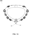
- FIGS. 13-15 illustrate various views of a ring assembly 500. Similar to ring assembly 100 as described above, the ring assembly 500 includes an outer tube, a set of posterior zone anchors, a set of anterior zone anchors, and a closure device 150. However, the ring assembly 500 as shown in FIGS. 13-15 can further include additional anchors 502 and 504 positioned adjacent to the closure device and configured to improve attachment of the ring assembly 500 to the patient's posterior annulus tissue. In certain implementations, the anchors 502 and 504 can be configured to be emitted in different directions and/or angles from one or more windows on the cross section of the outer tube in the area of the closure device.
- one or more additional anchors can be configured to be emitted to the ventricular side of the annulus tissue, and one or more of the additional anchors can be configured to be emitted to the atrial side of the annulus tissue.
- two or more additional anchors can be configured to be emitted from one window in the outer tube in different directions to each other.
- the anchors can include additional features such as hooks, barbs, or other similar features for increasing durability and preventing detachment.
- a ring assembly can further include bumps or other similar protrusions in the trigones area of the ring assembly.
- a ring assembly 600 (shown without anchors in FIG. 16 and with anchors in FIG. 17 ) can include bumps 602 and 604 positioned on the portion of the ring assembly that will be adjacent to the fibrous trigones region of a patient's heart.
- the bumps 602 and 604, or other similar protrusions or added features can provide for added contact between the ring assembly 600 and the patient's trigones region of the annulus tissue.
- achieving such contact can provide for better contact between the ring assembly 600 and the annulus tissue as compared to a ring assembly without the bumps in the trigones region. Similar to the ring assemblies as described above, various patterns and directions of anchors can be used to improve anchoring the ring assembly 600 to the annulus tissue as well.
- additional anchors can be beneficial for providing additional anchoring points for a ring assembly.
- a single anchor or set of additional anchors can be emitted from an existing window in an outer tube of a ring assembly providing a more robust anchoring point as compared to the curved anchors as described above.
- ring assembly 700 can include additional anchors configured to provide a more robust anchoring point.
- an additional anchor 702 can be emitted from a window for providing an additional anchoring point on the atrial side of the ring assembly 700.
- FIG. 19 illustrates an additional anchor 704 being emitted from a similar window for providing an additional anchoring point on the ventricular side of the ring assembly 700.
- FIG. 20 illustrates a set of two or more additional anchors emitting from a single window.
- additional anchors 702 and 704 provide additional anchoring into the atrial side and the ventricular side of the ring assembly 700 respectively.
- resizing the ring assembly can be desirable as a single ring assembly can accommodate an additional range of patients and valve sizes.
- a ring assembly can include a flexible connection that is laser cut from a similar material as the outer tube of the ring assembly.
- the flexible connection can be configured to contract and/or expand to allow for changing the size of the ring before, during, and/or after implantation of the ring assembly.
- the ring assembly can be manufactured from separate segments or components that are configured to be attached together with a mechanism or device that controls expansion and/or contraction of each side of a ring assembly separately or simultaneously.
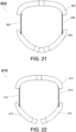
- FIG. 21 illustrates a ring assembly 800 that is configured to be resizable as described above.
- the ring assembly 800 can include an anterior portion 802 and a posterior portion 804.
- the anterior portion 802 and the posterior portion 804 can be connected together with a set of adjustable components 806 and 808.
- the adjustable components 806 and 808 can be made from a flexible material configured to expand and/or contract, thereby changing the overall size of the ring assembly 800.
- the anterior portion 802 and/or the posterior portion 804 can include an adjustment mechanism that is configured to interact with the adjustable components 806 and 808 to change the size, shape and/or geometry of the ring assembly 800.
- the adjustment mechanisms can include a ratcheting feature that is configured to interact with the adjustable components 806 and 808 to change the size of the ring assembly 800.
- a ratcheting feature is provided by way of example only. Additional adjustment mechanisms such as friction-based holding devices, snap-based devices, winding devices, and other similar adjustment devices can be used. Additionally, it should be noted that two adjustable components 806 and 808 are shown by way of example. In additional implementations, various numbers of adjustable components can be used. For example, a single adjustable component can be included on one side of the ring assembly.
- FIG. 22 illustrates a ring assembly 810 that is configured to be resizable, similar to ring assembly 800 as described above.
- the ring assembly 810 can include an anterior portion 812 and two posterior portions 814 and 815. Such an arrangement can provide for additional flexibility and sizing options when implanting the ring assembly 810.
- the anterior portion 812 can be connected to the posterior portion 815 with a first adjustable component 816.
- the anterior portion can be connected to the posterior portion 814 with a second adjustable component 818.
- the posterior portions 814 and 815 can be configured to releasably attach to one another via a closure device such as closure device 150 as described above.
- ring assemblies as described above can be designed and shaped for various functions such as mitral valve replacement.
- a similar ring assembly can be designed and constructed for tricuspid valve replacement as well.
- a tricuspid ring can be designed with additional features such as a release zone positioned on the ring assembly at a location that will be adjacent to a patient's atrioventricular node or valves.
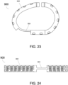
- FIGS. 23 and 24 illustrate an example tricuspid ring assembly 900 ( FIG. 23 illustrating a 3D view of the assembly, while FIG. 24 illustrates a flat cut pattern view).
- the outer tube 902 of the ring assembly 900 includes multiple windows through which anchors are emitted as described above.
- the ring assembly 900 can further include a release zone 904 configured and positioned at a location that will be adjacent to a patient's atrioventricular node or valves when the ring assembly is implanted.
- the release zone 904 does not have any anchors. Rather, the alternate shape and profile of the release zone provides for interference between the ring assembly 900 and the patient's atrioventricular node or valves, thereby securing the ring assembly in position.
- compositions, methods, and devices are described in terms of “comprising” various components or steps (interpreted as meaning “including, but not limited to”), the compositions, methods, and devices can also “consist essentially of” or “consist of the various components and steps, and such terminology should be interpreted as defining essentially closed-member groups. It will be further understood by those within the art that if a specific number of an introduced claim recitation is intended, such an intent will be explicitly recited in the claim, and in the absence of such recitation no such intent is present.
- a range includes each individual member.
- a group having 1-3 cells refers to groups having 1, 2, or 3 cells.
- a group having 1-5 cells refers to groups having 1, 2, 3, 4, or 5 cells, and so forth.
Landscapes
- Health & Medical Sciences (AREA)
- Cardiology (AREA)
- Life Sciences & Earth Sciences (AREA)
- General Health & Medical Sciences (AREA)
- Public Health (AREA)
- Biomedical Technology (AREA)
- Heart & Thoracic Surgery (AREA)
- Veterinary Medicine (AREA)
- Engineering & Computer Science (AREA)
- Animal Behavior & Ethology (AREA)
- Transplantation (AREA)
- Oral & Maxillofacial Surgery (AREA)
- Vascular Medicine (AREA)
- Surgery (AREA)
- Nuclear Medicine, Radiotherapy & Molecular Imaging (AREA)
- Medical Informatics (AREA)
- Molecular Biology (AREA)
- Rheumatology (AREA)
- Prostheses (AREA)
- Surgical Instruments (AREA)
Description
- The present application claims benefit of priority to the filing date of
U.S. Provisional Patent Application 62/472,633 filed March 17, 2017 - The present disclosure relates to implantable prosthetic devices. More specifically, the disclosure is directed to an improved prosthetic device implantable by catheter for the treatment of mitral or tricuspid regurgitation.
- Mitral Regurgitation is a valvular dysfunction that causes blood volume to flow during systole (during left ventricular contraction) from the left ventricle to the left atrium. In contrast, in a healthy heart, this direction of flow is blocked by the mitral valve. The reverse flow during systole causes pressure to rise in the left atrium, and maintaining a normal cardiac output results in an increased pressure in the left ventricle.
- Treating patients with MR (mitral regurgitation) or TR (tricuspid regurgitation) could require valve replacement in order to reduce or eliminate the regurgitation. For many years, the commonly accepted treatment was surgical repair or replacement of the native valve during open heart surgery. In recent years, a trans-vascular technique has been developed for introducing and implanting a prosthetic heart valve using a flexible catheter in a manner that is less invasive than open heart surgery.
- In the trans-vascular technique, a prosthetic valve is delivered to the target site (e.g., aortic valve, mitral valve, tricuspid valve, or other valve) through a catheter while the valve is crimped to a low diameter shaft. The valve is then expanded/deployed to a functional size when it is located in the correct position. Examples of such prosthetic valves, and related processes for delivering the valves through a catheter, are described in
U.S. Patent No. 8,518,107 . - Advancing the catheter to the target site can be achieved through: (a) The vascular system where a catheter is advanced from the femoral vein/artery, or any other blood vessel that allows access to the target site; (b) Trans-apically where a catheter is advanced through a small incision made in the chest wall and then through the apex; or (c) Trans-atrially where a catheter is advanced through a small incision made in the chest wall and then through the left or right atrium.
US2013289718 A1 discloses an annuloplasty ring with an anchor member configured to move a plurality of anchors with respect to a plurality of windows in an outer hollow member to deploy the plurality of anchors through the respective windows. - The invention is a prosthetic valve ring assembly as defined in claim 1. Embodiments herein are directed to various prosthetic valve ring assemblies for use in repairing cardiac valves suffering from, for example, mitral or tricuspid regurgitation.
- A prosthetic valve ring assembly is described herein. The prosthetic valve ring assembly includes an outer tube that includes a plurality of windows; and a plurality of anchors positioned inside the outer tube and about a perimeter of the outer tube. The plurality of anchors are configured to be emitted outward from the plurality of windows to anchor the prosthetic valve ring assembly to annulus tissue of a patient. The anchors are configured to be emitted in different directions. A first portion of the anchors are configured to be emitted to a ventricular side of the annulus tissue of the patient and a second portion of the anchors are configured to be emitted to an atrial side of the annulus tissue of the patient.
- In some embodiments, the anchors may be created using a laser cutting technique. In an embodiment, the laser cutting technique may include cutting according to a laser cut pattern to define a plurality of windows through which the plurality of anchors are configured to be emitted.
- In some embodiments, the prosthetic valve ring assembly may further include a closure device configured to lock a distal side and a proximal side of the prosthetic valve ring assembly. In some embodiments, the prosthetic valve ring assembly may further include a post adjustment mechanism that includes a flexible connection configured to move an anterior portion of the prosthetic valve ring assembly relative to a posterior portion of the prosthetic valve ring assembly, thereby changing at least one of a size and a geometry of the prosthetic valve ring assembly.
- In some embodiments, the prosthetic valve ring assembly may further include a closure device configured to lock a distal side and a proximal side of the prosthetic valve ring assembly; and an unlocking mechanism configured to unlock the closure device, thereby enabling repositioning or retrieval of the prosthetic valve ring assembly from a patient through a catheter. In some embodiments, the prosthetic valve ring assembly may further include one or more bumps positioned on a perimeter of the prosthetic valve ring assembly and configured to apply additional pressure to trigones of the annulus tissue of the patient, thereby providing improved anchoring of the prosthetic valve ring assembly.
- Aspects, features, benefits and advantages of the embodiments described herein will be apparent with regard to the following description, appended claims, and accompanying drawings where:
-
FIGS. 1-4 illustrate various views of an improved mitral valve ring, in accordance with at least one embodiment of the present disclosure. -
FIG. 5 illustrates a ring laser cut pattern, in accordance with at least one embodiment of the present disclosure. -
FIGS. 6 and 7 illustrate a laser cut pattern for posterior and/or anterior zone anchors, in accordance with at least one embodiment of the present disclosure. -
FIGS. 8 and 9 illustrate posterior and/or anterior zone anchors, in accordance with at least one embodiment of the present disclosure. -
FIGS. 10-12 illustrate a closure device, in accordance with at least one embodiment of the present disclosure. -
FIGS. 13-15 illustrate a mitral valve ring that includes anchors adjacent to the closure device area, in accordance with at least one embodiment of the present disclosure. -
FIGS. 16 and 17 illustrate an alternative ring assembly including bumps in the trigones region for additional tissue contact, in accordance with at least one embodiment of the present disclosure. -
FIGS. 18-20 illustrate an alternative mitral valve ring that includes additional anchors, in accordance with at least one embodiment of the present disclosure. -
FIGS. 21 and 22 illustrate an alternative mitral valve ring with one or more post adjustment mechanisms, in accordance with at least one embodiment of the present disclosure. -
FIGS. 23 and 24 illustrate a tricuspid ring, in accordance with at least one embodiment of the present disclosure. - This disclosure is not limited to the particular systems, devices and methods described, as these may vary. The terminology used in the description is for the purpose of describing the particular versions or embodiments only, and is not intended to limit the scope.
- As used in this document, the singular forms "a," "an," and "the" include plural references unless the context clearly dictates otherwise. Unless defined otherwise, all technical and scientific terms used herein have the same meanings as commonly understood by one of ordinary skill in the art. Nothing in this disclosure is to be construed as an admission that the embodiments described in this disclosure are not entitled to antedate such disclosure by virtue of prior invention. As used in this document, the term "comprising" means "including, but not limited to."
- When implanting a replacement valve (e.g., an aortic valve, mitral valve, tricuspid valve, or other valve), the replacement valve can include a prosthesis attachment. The prosthesis can be configured to secure the replacement valve in a patient's heart. An example of such a prosthesis is the AMEND™ Mitral Valve Repair Annuloplasty ring developed by Valcare Medical. The AMEND™ ring is a D-shaped ring configured to emulate the total valve replacement for patients who suffer from Mitral Regurgitation (MR, as described above). Additional detail related to prosthetic valves for mitral or tricuspid valve replacement can be found in
U.S. Patent Application No. 14/891,189 entitled "Transcatheter Prosthetic Valve for Mitral or Tricuspid Valve Replacement," filed May 22, 2013 - As described herein, a prosthetic ring can be configured to include various anchor zones on a posterior side. The anchor zones are positioned to emit anchors in different directions and/or angles from two or more windows on the cross section of the ring. A portion of the anchors are emitted to the ventricular side of the annulus tissue, and a portion of the anchors are emitted to the atrial side of the annulus tissue. Such an arrangement can provide for improved anchoring of the ring into the annulus tissue as compared to conventional mitral valve rings.
- It should be noted that, while the following detailed description of the figures is directed to a prosthetic ring configured to anchor a replacement valve such as the AMEND™ ring as described above, the techniques, ideas, and processes described herein can be applied to any mitral valve ring.
-
FIGS. 1-4 illustrate various views of an improvedmitral valve ring 100. In certain implementations, thering 100 can include posterior side anchor zones that are configured to emit anchors in different directions and/or angles from two or more windows on the cross section of the ring. A portion of the anchors are configured to be emitted to the ventricular side of a patient's annulus tissue, while a second portion of the anchors are configured to be emitted to the atrial side of the annulus tissue. Thus, two or more anchors can be emitted from one window in different directions. -
FIG. 1 illustrates a top view of thering assembly 100. Thering assembly 100 includes anouter tube 102 that defines the shape of the ring assembly. Theouter tube 102 includes one or more windows about its circumference as well as one or more windows in its cross-section. Anchors are positioned and configured to extend through these windows. Thering assembly 100 can also include a set of posterior zone anchors 110. As shown inFIG. 1 , the posterior zone anchors 110 are generally positioned on the posterior of thering assembly 100. Thering assembly 100 can further include anterior zone anchors 120 generally positioned on the anterior of the ring assembly. - Each anchor zone (including both posterior zone anchors 110 and anterior zone anchors 120) includes atrial side anchors 111 as well as ventricular side anchors 112 (not shown in
FIG. 1 but illustrated in, for example,FIG. 2 ). As noted above, in certain implementations, upon insertion of thering assembly 100, the atrial side anchors 111 are configured to be emitted into the atrial side of the patient's annulus tissue and the ventricular side anchors are configured to be emitted into the ventricular side of the patient's annulus tissue. - As further shown in
FIG. 1 , thering assembly 100 can include aclosure device 150. Theclosure device 150 can be configured to lock a distal end of thering assembly 100 to a proximal end of the ring assembly. Theclosure device 150 can also be designed and configured to removably attach to a delivery system for the valve replacement implant. For example, in certain implementations, theclosure device 150 can include apivot pin 153 that is configured to removably attach thering assembly 100 to a delivery device as well as provide for rotation of the ring assembly when emitted from the delivery device. For example, thepivot pin 153 can be configured to provide for 90 degrees of rotation of thering assembly 100. In other implementations, the pivot pin can be configured to provide for additional ranges of rotation such as 75-105 degrees of rotation, 60-120 degrees of rotation, and other similar ranges of rotation. - The
ring assembly 100 can further include a set ofpins 103. Thepins 103 can be positioned and configured to connect theouter tube 102 to theclosure device 150. In certain implementations, thepins 103 can be further positioned and configured to provide for routing of sutures as well as to function as a pulley while providing for rotation of a suture (e.g., 90 degree rotation) with minimal friction. -
FIG. 2 illustrates a first side view of thering assembly 100, shown from the posterior and further illustrating theclosure device 150.FIG. 2 further illustrates the alternate emitting directions of the atrial side anchors 111 and the ventricular side anchors 112. -
FIG. 3 illustrates a bottom view of thering assembly 100. In contrast toFIG. 1 ,FIG. 3 illustrates the ventricular side anchors 112.FIG. 3 further illustrates additional anterior side anchors 120 that were obscured from view inFIG. 1 . - Additionally, in certain embodiments, various anchors can be configured such that portions of the anchors can cross one another in different directions, thereby creating a closed loop and stapling effect of the tissue. For example, anchors 121 and 122 as shown in
FIG. 3 are configured to cross one another in different directions, thereby having a stapling effect on the adjacent tissue, securely locking thering assembly 100 into position. -
FIG. 4 illustrates a second side view of thering assembly 100, shown further illustrating the crossing anchors 121 and 122. - The raw materials of the
ring assembly 100 and various components included therein can be selected from various materials, such as various polymers, shape memory materials such as Nitinol, metals such as stainless steel, or other similar materials safe for implanting into or adjacent to living tissue. In certain implementations, thering assembly 100 can include a combination of two or more different materials, such as stainless steel 316/316L and Nitinol. This combination is provided by way of example only, and other materials can be used alternately or additionally, - In order to create the
ring assembly 100 as described above, theouter tube 102 is manufactured such that multiple windows are defined. The windows are positioned to facilitate deployment of the various anchors as described above.FIG. 5 illustrates anexample cut pattern 200 for creating theouter tube 102 as described above. For example, thepattern 200 shows an example cut pattern of aring tube 202 withseveral windows windows 204D, and anchors can be emitted from the ventricular side fromwindows 204C. - In an alternate embodiment, more than one anchor can be emitted from one window with one or more anchors in the atrial side and one or more anchors in ventricular side. In another embodiment, one or more anchors can be emitted from different windows in the same direction. For example, two windows (e.g., 204A and 204B) can be configured to provide for simultaneous deployment of anchors towards the ventricular side.
-
FIGS. 6 and 7 illustrate example cut patterns (e.g., laser cut patterns) for the anterior and/or posterior zone anchors such as posterior zone anchors 110 and anterior zone anchors 120 as described above. Additionally, as noted above, anchors can be emitted in both the atrial and ventricle directions, such asatrial anchors 111 and ventricle anchors 112 as described above. - To achieve such a configuration, cut
pattern 300 as shown inFIGS. 6 and 7 can be used to create one ormore anchor zones 302. The cut pattern can define a set ofatrial anchors 304 and a set of ventricle anchors 306 within theanchor zone 302. Thecut pattern 300 can also define ananchor stop feature 308. The anchor stop feature 308 can be configured to lock theanchor zone 302 into, for example, the outer tube of a ring assembly to prevent unintentional movement of the anchor zone. - In certain implementations, the anchor stop feature 308 can be a passive feature that is activated as a result of a force exerted on the anchor zone 302 (e.g., a pulling force) causing a bending or other change to the geometry of the
anchor stop feature 308. In other embodiments, the anchor stop feature 308 can include an associated activation mechanism that facilitates activation of the anchor stop feature. For example, the activation mechanism can be an activation pulley that prevents the anchor stop feature 308 from bending of otherwise deforming such that a portion of the anchor stop feature exits through a corresponding hole on the outer tube of the ring assembly. Such an arrangement can lock theanchor zone 302 into position as theanchor stop feature 308 prevents any relative movement. In some examples, pulling on the activator mechanism and removing it from the designated location allows the anchor stop feature 308 to bend and allows relative movement of theanchor zone 302 in relation to the outer tube of the ring assembly. - In certain implementations, the anchor stop feature 308 can be located in either the ventricular side or atrial side of the anchor zone 320 and/or outer tube. Additionally, in various embodiments, the anchor stop feature 308 can be positioned in any location along the
anchor zone 302. The position as shown inFIGS. 6 and 7 is shown by way of example only. - It should be noted that laser cutting the ring assemblies as described herein is provided by way of example only, and additional manufacturing techniques can be used. For example, a stamping process can be used to stamp the cut patterns as described above.
-
FIGS. 8 and 9 illustrate thecut patterns 300 as described above in regard toFIGS. 6 and 7 that have been, for example, heat treated and to include various bends and curves, thereby defining a specific three-dimensional shape for theanchor zones 302. For example, theanchor zones 302 can be heat-treated and bent at an angle selected from a range of angles. For example, in certain implementations the range of angles can be from zero degrees (e.g., no additional bending) to 135 degrees. As shown inFIGS. 8 and 9 , the ventricle anchors 306 can be heat-treated to 45 degrees, and theatrial anchors 304 can be heat-treated to 60 degrees. - In addition, the anchor zone can have a 3D shape that fits the zone location in the final ring assembly. For example, the posterior anchor zones can be curved to fit the posterior curvature of the ring assembly, and the anterior anchor zones can be curved to fit the anterior curvature of the ring assembly.
- It should be noted that heat-treated bending and curving is provided by way of example only. Depending upon the type of material being used and the design of the individual components such as the anchor zones, alternative bending and curving techniques can be used to form the anchor zones to the geometry of the final ring assembly.
-
FIGS. 10-12 illustrate detailed views of aclosing mechanism 400 for a ring assembly, such asclosing mechanism 150 as described above in regard toring assembly 100. In certain implementations, a closing mechanism can include a female component configured to lock to a male component. For example,FIGS. 10-12 illustrate various views and embodiments of thefemale component 402. As shown inFIG. 10 , thefemale component 402 can include a locking mechanism for releasably attaching to a male component orcup 404. - The
female component 402 can further include anunsnapping pin 406. The unsnapping pin can be positioned and configured to unsnap or otherwise disconnect thefemale component 402 from thecup 404 of the ring assembly. Additionally, thefemale component 402 can include apivot pin 408 for attaching the female component to an outer tube of the ring assembly. Additionally, thepivot pin 408 can be configured to function as an interface between the ring assembly and a delivery system, similar topins 103 as described above. -
FIG. 11 illustrates a cross-section of thefemale component 402. As shown in the cross-sectional view, thefemale component 402 can include adisk 410. Thedisk 410 can be positioned to abut an end of thecup 404 when inserted into thefemale component 402 to provide for locking of the male component to the female component. In some examples, thedisk 410 can be held in position with a cover. -
FIG. 12 illustrates a view of thelocking mechanism 400 with a portion of thecup 404 removed, showing additional detail of theunsnapping pin 406. As shown inFIG. 12 , theunsnapping pin 406 can be designed with two individual fingers extending from a central point such that, upon exerting a force (e.g., a squeezing force) upon an end of the fingers opposite the central point, the fingers deflect about the point. Upon deflection of theunsnapping pin 406, the unsnapping pin can be removed, thereby releasing the male component (e.g., cup 404) from thefemale component 402. - In certain implementations, the
disk 410 and theunsnapping pin 406 can be made from a shape memory alloy such as Nitinol. In some example, the other components of the female component can be made from various metallic materials such as stainless steel, aluminum, Nitinol, and titanium. - As noted above, the
cup 404 and thefemale component 402 are attached together with theunsnapping pin 406. If properly inserted and positioned, theunsnapping pin 406 can visually verify that the two parts are well-attached and cannot open unintentionally. Conversely, upon activation of theunsnapping pin 406 by pulling it in a specific direction, it allows separation of the two components. By doing this, the ring close structure is compromised and the closed shape becomes open and allows retrieval of the implant into the delivery system. - In some embodiments, the
female component 402 can have one or moregold markers 412 that provide for confirmation of locking of thecup 404 and the female component during a clinical procedure. -
FIGS. 13-15 illustrate various views of aring assembly 500. Similar to ring assembly 100 as described above, thering assembly 500 includes an outer tube, a set of posterior zone anchors, a set of anterior zone anchors, and aclosure device 150. However, thering assembly 500 as shown inFIGS. 13-15 can further includeadditional anchors ring assembly 500 to the patient's posterior annulus tissue. In certain implementations, theanchors - In certain implementations, a ring assembly can further include bumps or other similar protrusions in the trigones area of the ring assembly. For example, as shown in
FIGS. 16 and 17 , a ring assembly 600 (shown without anchors inFIG. 16 and with anchors inFIG. 17 ) can includebumps bumps ring assembly 600 and the patient's trigones region of the annulus tissue. In some implementations, achieving such contact can provide for better contact between thering assembly 600 and the annulus tissue as compared to a ring assembly without the bumps in the trigones region. Similar to the ring assemblies as described above, various patterns and directions of anchors can be used to improve anchoring thering assembly 600 to the annulus tissue as well. - In certain implementations, additional anchors can be beneficial for providing additional anchoring points for a ring assembly. In some examples, a single anchor or set of additional anchors can be emitted from an existing window in an outer tube of a ring assembly providing a more robust anchoring point as compared to the curved anchors as described above. For example, as shown in
FIGS. 18-20 ,ring assembly 700 can include additional anchors configured to provide a more robust anchoring point. As shown inFIG. 18 , anadditional anchor 702 can be emitted from a window for providing an additional anchoring point on the atrial side of thering assembly 700.FIG. 19 illustrates anadditional anchor 704 being emitted from a similar window for providing an additional anchoring point on the ventricular side of thering assembly 700.FIG. 20 illustrates a set of two or more additional anchors emitting from a single window. In this example,additional anchors ring assembly 700 respectively. - In some implementations, resizing the ring assembly can be desirable as a single ring assembly can accommodate an additional range of patients and valve sizes. For example, a ring assembly can include a flexible connection that is laser cut from a similar material as the outer tube of the ring assembly. The flexible connection can be configured to contract and/or expand to allow for changing the size of the ring before, during, and/or after implantation of the ring assembly. In some examples, the ring assembly can be manufactured from separate segments or components that are configured to be attached together with a mechanism or device that controls expansion and/or contraction of each side of a ring assembly separately or simultaneously.
-
FIG. 21 illustrates aring assembly 800 that is configured to be resizable as described above. Thering assembly 800 can include ananterior portion 802 and aposterior portion 804. Theanterior portion 802 and theposterior portion 804 can be connected together with a set ofadjustable components adjustable components ring assembly 800. In certain implementations, theanterior portion 802 and/or theposterior portion 804 can include an adjustment mechanism that is configured to interact with theadjustable components ring assembly 800. For example, the adjustment mechanisms can include a ratcheting feature that is configured to interact with theadjustable components ring assembly 800. - It should be noted that a ratcheting feature is provided by way of example only. Additional adjustment mechanisms such as friction-based holding devices, snap-based devices, winding devices, and other similar adjustment devices can be used. Additionally, it should be noted that two
adjustable components -
FIG. 22 illustrates aring assembly 810 that is configured to be resizable, similar toring assembly 800 as described above. However, thering assembly 810 can include ananterior portion 812 and twoposterior portions ring assembly 810. - In some implementations, the
anterior portion 812 can be connected to theposterior portion 815 with a firstadjustable component 816. Similarly, the anterior portion can be connected to theposterior portion 814 with a secondadjustable component 818. Theposterior portions closure device 150 as described above. - The ring assemblies as described above can be designed and shaped for various functions such as mitral valve replacement. However, a similar ring assembly can be designed and constructed for tricuspid valve replacement as well. However, a tricuspid ring can be designed with additional features such as a release zone positioned on the ring assembly at a location that will be adjacent to a patient's atrioventricular node or valves.
-
FIGS. 23 and 24 illustrate an example tricuspid ring assembly 900 (FIG. 23 illustrating a 3D view of the assembly, whileFIG. 24 illustrates a flat cut pattern view). Theouter tube 902 of thering assembly 900 includes multiple windows through which anchors are emitted as described above. However, thering assembly 900 can further include arelease zone 904 configured and positioned at a location that will be adjacent to a patient's atrioventricular node or valves when the ring assembly is implanted. - In certain implementations, the
release zone 904 does not have any anchors. Rather, the alternate shape and profile of the release zone provides for interference between thering assembly 900 and the patient's atrioventricular node or valves, thereby securing the ring assembly in position. - In the above detailed description, reference is made to the accompanying drawings, which form a part hereof. In the drawings, similar symbols typically identify similar components, unless context dictates otherwise. The illustrative embodiments described in the detailed description, drawings, and claims are not meant to be limiting. Other embodiments may be used, and other changes may be made, without departing from the scope of the claimed subject matter presented herein. It will be readily understood that the aspects of the present disclosure, as generally described herein, and illustrated in the Figures, can be arranged, substituted, combined, separated, and designed in a wide variety of different configurations, all of which are explicitly contemplated herein.
- The present disclosure is not to be limited in terms of the particular embodiments described in this application, which are intended as illustrations of various aspects. Many modifications and variations can be made without departing from the scope of the claims, as will be apparent to those skilled in the art. Functionally equivalent methods and apparatuses within the scope of the disclosure, in addition to those enumerated herein, will be apparent to those skilled in the art from the foregoing descriptions. Such modifications and variations are intended to fall within the scope of the appended claims. The present disclosure is to be limited only by the terms of the appended claims, along with the full scope of equivalents to which such claims are entitled. It is to be understood that this disclosure is not limited to particular methods, reagents, compounds, compositions or biological systems, which can, of course, vary. It is also to be understood that the terminology used herein is for the purpose of describing particular embodiments only, and is not intended to be limiting.
- With respect to the use of substantially any plural and/or singular terms herein, those having skill in the art can translate from the plural to the singular and/or from the singular to the plural as is appropriate to the context and/or application. The various singular/plural permutations may be expressly set forth herein for sake of clarity.
- It will be understood by those within the art that, in general, terms used herein, and especially in the appended claims (for example, bodies of the appended claims) are generally intended as "open" terms (for example, the term "including" should be interpreted as "including but not limited to," the term "having" should be interpreted as "having at least," the term "includes" should be interpreted as "includes but is not limited to," et cetera). While various compositions, methods, and devices are described in terms of "comprising" various components or steps (interpreted as meaning "including, but not limited to"), the compositions, methods, and devices can also "consist essentially of" or "consist of the various components and steps, and such terminology should be interpreted as defining essentially closed-member groups. It will be further understood by those within the art that if a specific number of an introduced claim recitation is intended, such an intent will be explicitly recited in the claim, and in the absence of such recitation no such intent is present.
- For example, as an aid to understanding, the following appended claims may contain usage of the introductory phrases "at least one" and "one or more" to introduce claim recitations. However, the use of such phrases should not be construed to imply that the introduction of a claim recitation by the indefinite articles "a" or "an" limits any particular claim containing such introduced claim recitation to embodiments containing only one such recitation, even when the same claim includes the introductory phrases "one or more" or "at least one" and indefinite articles such as "a" or "an" (for example, "a" and/or "an" should be interpreted to mean "at least one" or "one or more"); the same holds true for the use of definite articles used to introduce claim recitations.
- In addition, even if a specific number of an introduced claim recitation is explicitly recited, those skilled in the art will recognize that such recitation should be interpreted to mean at least the recited number (for example, the bare recitation of "two recitations," without other modifiers, means at least two recitations, or two or more recitations). Furthermore, in those instances where a convention analogous to "at least one of A, B, and C, et cetera" is used, in general such a construction is intended in the sense one having skill in the art would understand the convention (for example, "a system having at least one of A, B, and C" would include but not be limited to systems that have A alone, B alone, C alone, A and B together, A and C together, B and C together, and/or A, B, and C together, et cetera). In those instances where a convention analogous to "at least one of A, B, or C, et cetera" is used, in general such a construction is intended in the sense one having skill in the art would understand the convention (for example, "a system having at least one of A, B, or C" would include but not be limited to systems that have A alone, B alone, C alone, A and B together, A and C together, B and C together, and/or A, B, and C together, et cetera). It will be further understood by those within the art that virtually any disjunctive word and/or phrase presenting two or more alternative terms, whether in the description, claims, or drawings, should be understood to contemplate the possibilities of including one of the terms, either of the terms, or both terms. For example, the phrase "A or B" will be understood to include the possibilities of "A" or "B" or "A and B."
- In addition, where features or aspects of the disclosure are described in terms of Markush groups, those skilled in the art will recognize that the disclosure is also thereby described in terms of any individual member or subgroup of members of the Markush group.
- As will be understood by one skilled in the art, for any and all purposes, such as in terms of providing a written description, all ranges disclosed herein also encompass any and all possible subranges and combinations of subranges thereof. Any listed range can be easily recognized as sufficiently describing and enabling the same range being broken down into at least equal halves, thirds, quarters, fifths, tenths, et cetera. As a non-limiting example, each range discussed herein can be readily broken down into a lower third, middle third and upper third, et cetera. As will also be understood by one skilled in the art all language such as "up to," "at least," and the like include the number recited and refer to ranges that can be subsequently broken down into subranges as discussed above. Finally, as will be understood by one skilled in the art, a range includes each individual member. Thus, for example, a group having 1-3 cells refers to groups having 1, 2, or 3 cells. Similarly, a group having 1-5 cells refers to groups having 1, 2, 3, 4, or 5 cells, and so forth.
- Various of the above-disclosed and other features and functions, or alternatives thereof, may be combined into many other different systems or applications. Various presently unforeseen or unanticipated alternatives, modifications, variations or improvements therein may be subsequently made by those skilled in the art, each of which is also intended to be encompassed by the disclosed embodiments.
Claims (7)
- A prosthetic valve ring assembly (100, 600, 800, 900), comprising:an outer tube (102) comprising a plurality of windows; anda plurality of anchors (110, 111, 112, 120) positioned inside the outer tube (102) and about a perimeter of the outer tube (102), wherein the plurality of anchors (110, 111, 112, 120) are configured to be emitted outward from the plurality of windows to anchor the prosthetic valve ring assembly (100) to a patient's annulus tissue;characterised in that the plurality of anchors (110, 111, 112, 120) are configured to be emitted in different directions, and wherein a first portion of the plurality of anchors (112) is configured to be emitted to a ventricular side of the annulus tissue, and a second portion (111) of the plurality of anchors is configured to be emitted to an atrial side of the annulus tissue.
- The prosthetic valve ring assembly (100) of Claim 1, wherein the plurality of anchors (110, 111, 112, 120) are created using a laser cutting technique.
- The prosthetic valve ring assembly (100) of claim 2, wherein the laser cutting technique comprises cutting according to a laser cut pattern to define a plurality of windows through which the plurality of anchors (110, 111, 112, 120) are configured to be emitted.
- The prosthetic valve ring assembly (100) of any one of the preceding claims, further comprising a closure device (150) configured to lock a distal side and a proximal side of the prosthetic valve ring assembly (100).
- The prosthetic valve ring assembly (800) of any one of the preceding claims, further comprising a post adjustment mechanism comprising a flexible connection configured to move an anterior portion (802) of the prosthetic valve ring assembly (800) relative to a posterior portion (804) of the prosthetic valve ring assembly (800), thereby changing at least one of a size and a geometry of the prosthetic valve ring assembly (800).
- The prosthetic valve ring assembly (100) of any one of the preceding claims, further comprising:a closure device (400) configured to lock a distal side and a proximal side of the prosthetic valve ring assembly (100); andan unlocking mechanism (406) configured to unlock the closure device (400), thereby providing for repositioning or retrieval of the prosthetic valve ring assembly (100) from the patient through a catheter.
- The prosthetic valve ring assembly (600) of any one of the preceding claims, further comprising one or more bumps (602, 604) positioned on a perimeter of the prosthetic valve ring assembly (600) and configured to apply additional pressure to trigones of the patient's annulus tissue, thereby providing improved anchoring of the prosthetic valve ring assembly (600).
Priority Applications (1)
| Application Number | Priority Date | Filing Date | Title |
|---|---|---|---|
| EP24219902.4A EP4501386A3 (en) | 2017-03-17 | 2018-03-16 | Mitral or tricuspid repair systems with multi-directional anchors |
Applications Claiming Priority (2)
| Application Number | Priority Date | Filing Date | Title |
|---|---|---|---|
| US201762472633P | 2017-03-17 | 2017-03-17 | |
| PCT/US2018/022910 WO2018170424A1 (en) | 2017-03-17 | 2018-03-16 | Mitral or tricuspid repair systems with multi-directional anchors |
Related Child Applications (1)
| Application Number | Title | Priority Date | Filing Date |
|---|---|---|---|
| EP24219902.4A Division EP4501386A3 (en) | 2017-03-17 | 2018-03-16 | Mitral or tricuspid repair systems with multi-directional anchors |
Publications (4)
| Publication Number | Publication Date |
|---|---|
| EP3595542A1 EP3595542A1 (en) | 2020-01-22 |
| EP3595542A4 EP3595542A4 (en) | 2020-11-18 |
| EP3595542C0 EP3595542C0 (en) | 2025-01-15 |
| EP3595542B1 true EP3595542B1 (en) | 2025-01-15 |
Family
ID=63522706
Family Applications (2)
| Application Number | Title | Priority Date | Filing Date |
|---|---|---|---|
| EP18768197.8A Active EP3595542B1 (en) | 2017-03-17 | 2018-03-16 | Mitral or tricuspid repair systems with multi-directional anchors |
| EP24219902.4A Pending EP4501386A3 (en) | 2017-03-17 | 2018-03-16 | Mitral or tricuspid repair systems with multi-directional anchors |
Family Applications After (1)
| Application Number | Title | Priority Date | Filing Date |
|---|---|---|---|
| EP24219902.4A Pending EP4501386A3 (en) | 2017-03-17 | 2018-03-16 | Mitral or tricuspid repair systems with multi-directional anchors |
Country Status (5)
| Country | Link |
|---|---|
| US (3) | US11576779B2 (en) |
| EP (2) | EP3595542B1 (en) |
| CN (2) | CN121987389A (en) |
| IL (2) | IL269420B2 (en) |
| WO (1) | WO2018170424A1 (en) |
Families Citing this family (37)
| Publication number | Priority date | Publication date | Assignee | Title |
|---|---|---|---|---|
| EP2819619B1 (en) | 2012-02-29 | 2019-01-16 | ValCare, Inc. | Percutaneous annuloplasty system with anterior-posterior adjustment |
| US20200146854A1 (en) | 2016-05-16 | 2020-05-14 | Elixir Medical Corporation | Methods and devices for heart valve repair |
| CN107753153B (en) | 2016-08-15 | 2022-05-31 | 沃卡尔有限公司 | Device and method for treating heart valve insufficiency |
| CN121987389A (en) | 2017-03-17 | 2026-05-08 | 沃卡尔医药有限公司 | Mitral or tricuspid valve repair system with multidirectional anchor |
| WO2019195860A2 (en) | 2018-04-04 | 2019-10-10 | Vdyne, Llc | Devices and methods for anchoring transcatheter heart valve |
| US10595994B1 (en) | 2018-09-20 | 2020-03-24 | Vdyne, Llc | Side-delivered transcatheter heart valve replacement |
| US11071627B2 (en) | 2018-10-18 | 2021-07-27 | Vdyne, Inc. | Orthogonally delivered transcatheter heart valve frame for valve in valve prosthesis |
| US11278437B2 (en) | 2018-12-08 | 2022-03-22 | Vdyne, Inc. | Compression capable annular frames for side delivery of transcatheter heart valve replacement |
| US11344413B2 (en) | 2018-09-20 | 2022-05-31 | Vdyne, Inc. | Transcatheter deliverable prosthetic heart valves and methods of delivery |
| US10321995B1 (en) | 2018-09-20 | 2019-06-18 | Vdyne, Llc | Orthogonally delivered transcatheter heart valve replacement |
| US12186187B2 (en) | 2018-09-20 | 2025-01-07 | Vdyne, Inc. | Transcatheter deliverable prosthetic heart valves and methods of delivery |
| US11109969B2 (en) | 2018-10-22 | 2021-09-07 | Vdyne, Inc. | Guidewire delivery of transcatheter heart valve |
| WO2020117842A1 (en) * | 2018-12-03 | 2020-06-11 | Valcare, Inc. | Stabilizing and adjusting tool for controlling a minimally invasive mitral / tricuspid valve repair system |
| US11253359B2 (en) | 2018-12-20 | 2022-02-22 | Vdyne, Inc. | Proximal tab for side-delivered transcatheter heart valves and methods of delivery |
| US10653522B1 (en) | 2018-12-20 | 2020-05-19 | Vdyne, Inc. | Proximal tab for side-delivered transcatheter heart valve prosthesis |
| WO2020146842A1 (en) | 2019-01-10 | 2020-07-16 | Vdyne, Llc | Anchor hook for side-delivery transcatheter heart valve prosthesis |
| US11185409B2 (en) | 2019-01-26 | 2021-11-30 | Vdyne, Inc. | Collapsible inner flow control component for side-delivered transcatheter heart valve prosthesis |
| US11273032B2 (en) | 2019-01-26 | 2022-03-15 | Vdyne, Inc. | Collapsible inner flow control component for side-deliverable transcatheter heart valve prosthesis |
| CA3132162A1 (en) | 2019-03-05 | 2020-09-10 | Vdyne, Inc. | Tricuspid regurgitation control devices for orthogonal transcatheter heart valve prosthesis |
| US11076956B2 (en) | 2019-03-14 | 2021-08-03 | Vdyne, Inc. | Proximal, distal, and anterior anchoring tabs for side-delivered transcatheter mitral valve prosthesis |
| US10631983B1 (en) | 2019-03-14 | 2020-04-28 | Vdyne, Inc. | Distal subannular anchoring tab for side-delivered transcatheter valve prosthesis |
| US10758346B1 (en) | 2019-03-14 | 2020-09-01 | Vdyne, Inc. | A2 clip for side-delivered transcatheter mitral valve prosthesis |
| US11173027B2 (en) | 2019-03-14 | 2021-11-16 | Vdyne, Inc. | Side-deliverable transcatheter prosthetic valves and methods for delivering and anchoring the same |
| CN114072106B (en) | 2019-05-04 | 2025-09-19 | 维迪内股份有限公司 | Lacing devices and methods for deploying a side-delivered prosthetic heart valve in a native annulus |
| EP3982844A4 (en) | 2019-06-11 | 2023-05-10 | Valcare, Inc. | SYSTEMS AND METHODS OF INSERTION OF A TENDON REPLACEMENT SYSTEM |
| WO2020252200A1 (en) * | 2019-06-11 | 2020-12-17 | Valcare, Inc. | Annuloplasty ring with posterior leaflet for minimally invasive treatment |
| CN114173713A (en) * | 2019-07-15 | 2022-03-11 | 沃卡尔有限公司 | Transcatheter bioprosthetic member and support structure |
| US12502167B2 (en) | 2019-07-16 | 2025-12-23 | Edwards Lifesciences Corporation | Tissue remodeling systems and methods |
| EP4480458B1 (en) | 2019-08-20 | 2026-08-12 | VDyne, Inc. | Delivery devices for side-deliverable transcatheter prosthetic valves |
| CN114630665B (en) | 2019-08-26 | 2025-06-17 | 维迪内股份有限公司 | Laterally deliverable transcatheter prosthetic valve and method of delivering and anchoring the same |
| WO2021146515A1 (en) | 2020-01-17 | 2021-07-22 | Vdyne, Inc. | Ventricular stability elements for side-deliverable prosthetic heart valves and methods of delivery |
| WO2021179065A1 (en) * | 2020-03-09 | 2021-09-16 | Vesalius Cardiovascular Inc. | Apparatus and methods for clamping a mitral valve |
| CN212490265U (en) * | 2020-08-31 | 2021-02-09 | 宁波健世生物科技有限公司 | Anti-drop anchoring mechanism applied to implanted prosthesis |
| US12648850B2 (en) | 2021-08-09 | 2026-06-09 | Valcare Medical, Inc. | Systems and methods for target/article bridging engagement and anchoring |
| AU2023358759A1 (en) | 2022-10-14 | 2025-05-15 | Vdyne, Inc. | Devices and methods for delivering a prosthetic heart valve using supra-annular support |
| CN117100459B (en) * | 2023-10-20 | 2024-08-20 | 北京新尖科技有限公司 | Valve stent and valve prosthesis |
| US12642654B2 (en) | 2024-10-21 | 2026-06-02 | Valcare Medical, Inc. | Transcatheter annuloplasty system and methods |
Family Cites Families (269)
| Publication number | Priority date | Publication date | Assignee | Title |
|---|---|---|---|---|
| GB1496804A (en) | 1975-09-09 | 1978-01-05 | Wolf Gmbh Richard | Supported laryngoscopes |
| FI61281C (en) | 1978-10-02 | 1982-07-12 | Span Deck Inc | BETONGGJUTESUNDERLAGSANLAEGGNING |
| DE3230858C2 (en) | 1982-08-19 | 1985-01-24 | Ahmadi, Ali, Dr. med., 7809 Denzlingen | Ring prosthesis |
| US4805599A (en) | 1987-06-25 | 1989-02-21 | Cedar Surgical, Inc. | Framework for supporting surgical instruments at a surgical wound |
| US4874378A (en) | 1988-06-01 | 1989-10-17 | Cordis Corporation | Catheter sheath introducer |
| WO1990009153A1 (en) | 1989-02-13 | 1990-08-23 | Baxter International Inc. | Selectively flexible annuloplasty ring |
| US5080662A (en) | 1989-11-27 | 1992-01-14 | Paul Kamaljit S | Spinal stereotaxic device and method |
| US5695518A (en) | 1990-12-28 | 1997-12-09 | Laerum; Frode | Filtering device for preventing embolism and/or distension of blood vessel walls |
| US5306296A (en) | 1992-08-21 | 1994-04-26 | Medtronic, Inc. | Annuloplasty and suture rings |
| CN2114422U (en) | 1992-02-28 | 1992-09-02 | 深圳安科高技术有限公司 | High preision head three-dimentional directional apparatus |
| US5236440A (en) | 1992-04-14 | 1993-08-17 | American Cyanamid Company | Surgical fastener |
| US5797960A (en) | 1993-02-22 | 1998-08-25 | Stevens; John H. | Method and apparatus for thoracoscopic intracardiac procedures |
| JP2843507B2 (en) | 1994-08-09 | 1999-01-06 | 三鷹光器株式会社 | Articulated instrument holding arm |
| US5976159A (en) | 1995-02-24 | 1999-11-02 | Heartport, Inc. | Surgical clips and methods for tissue approximation |
| US5716370A (en) | 1996-02-23 | 1998-02-10 | Williamson, Iv; Warren | Means for replacing a heart valve in a minimally invasive manner |
| US20030198605A1 (en) | 1998-02-13 | 2003-10-23 | Montgomery R. Eric | Light-activated tooth whitening composition and method of using same |
| US7371210B2 (en) | 1998-02-24 | 2008-05-13 | Hansen Medical, Inc. | Flexible instrument |
| US6113611A (en) | 1998-05-28 | 2000-09-05 | Advanced Vascular Technologies, Llc | Surgical fastener and delivery system |
| US6726704B1 (en) | 1998-05-29 | 2004-04-27 | By-Pass, Inc. | Advanced closure device |
| US6425916B1 (en) | 1999-02-10 | 2002-07-30 | Michi E. Garrison | Methods and devices for implanting cardiac valves |
| CA2369641C (en) | 1999-04-09 | 2009-02-10 | Evalve, Inc. | Methods and apparatus for cardiac valve repair |
| US6231602B1 (en) | 1999-04-16 | 2001-05-15 | Edwards Lifesciences Corporation | Aortic annuloplasty ring |
| AU4242800A (en) | 1999-04-23 | 2000-11-10 | St. Jude Medical Cardiovascular Group, Inc. | Artificial heart valve attachment apparatus |
| US6790229B1 (en) | 1999-05-25 | 2004-09-14 | Eric Berreklouw | Fixing device, in particular for fixing to vascular wall tissue |
| US6667175B1 (en) | 1999-06-15 | 2003-12-23 | The Trustees Of Columbia University | Generation of antigen specific T suppressor cells for treatment of rejection |
| JP4576521B2 (en) | 1999-06-25 | 2010-11-10 | ハンセン メディカル, インコーポレイテッド | Apparatus and method for treating tissue |
| US6626899B2 (en) | 1999-06-25 | 2003-09-30 | Nidus Medical, Llc | Apparatus and methods for treating tissue |
| SE514718C2 (en) | 1999-06-29 | 2001-04-09 | Jan Otto Solem | Apparatus for treating defective closure of the mitral valve apparatus |
| US6293906B1 (en) | 2000-01-14 | 2001-09-25 | Acorn Cardiovascular, Inc. | Delivery of cardiac constraint jacket |
| US6989028B2 (en) | 2000-01-31 | 2006-01-24 | Edwards Lifesciences Ag | Medical system and method for remodeling an extravascular tissue structure |
| US7296577B2 (en) | 2000-01-31 | 2007-11-20 | Edwards Lifescience Ag | Transluminal mitral annuloplasty with active anchoring |
| US6797002B2 (en) | 2000-02-02 | 2004-09-28 | Paul A. Spence | Heart valve repair apparatus and methods |
| DE60143514D1 (en) | 2000-02-11 | 2011-01-05 | Gen Hospital Corp | PHOTOCHEMICAL TISSUE CONNECTION |
| US6800671B1 (en) | 2000-04-21 | 2004-10-05 | Britesmile, Inc. | Low peak exotherm curable compositions |
| US6869444B2 (en) | 2000-05-22 | 2005-03-22 | Shlomo Gabbay | Low invasive implantable cardiac prosthesis and method for helping improve operation of a heart valve |
| US6805711B2 (en) | 2000-06-02 | 2004-10-19 | 3F Therapeutics, Inc. | Expandable medical implant and percutaneous delivery |
| US6964667B2 (en) | 2000-06-23 | 2005-11-15 | Sdgi Holdings, Inc. | Formed in place fixation system with thermal acceleration |
| GB2366319A (en) | 2000-08-26 | 2002-03-06 | Ramasubramanyan Chandrasekar | Hands-free retraction system for surgery |
| US8784482B2 (en) | 2000-09-20 | 2014-07-22 | Mvrx, Inc. | Method of reshaping a heart valve annulus using an intravascular device |
| US6893459B1 (en) | 2000-09-20 | 2005-05-17 | Ample Medical, Inc. | Heart valve annulus device and method of using same |
| US6447524B1 (en) | 2000-10-19 | 2002-09-10 | Ethicon Endo-Surgery, Inc. | Fastener for hernia mesh fixation |
| US7510576B2 (en) | 2001-01-30 | 2009-03-31 | Edwards Lifesciences Ag | Transluminal mitral annuloplasty |
| US6884249B2 (en) | 2001-02-16 | 2005-04-26 | Depuy Mitek, Inc. | Surgical knot pusher and method of use |
| US20060069429A1 (en) | 2001-04-24 | 2006-03-30 | Spence Paul A | Tissue fastening systems and methods utilizing magnetic guidance |
| US6619291B2 (en) | 2001-04-24 | 2003-09-16 | Edwin J. Hlavka | Method and apparatus for catheter-based annuloplasty |
| US7311731B2 (en) | 2001-04-27 | 2007-12-25 | Richard C. Satterfield | Prevention of myocardial infarction induced ventricular expansion and remodeling |
| US20020188170A1 (en) | 2001-04-27 | 2002-12-12 | Santamore William P. | Prevention of myocardial infarction induced ventricular expansion and remodeling |
| US20020165524A1 (en) | 2001-05-01 | 2002-11-07 | Dan Sanchez | Pivot point arm for a robotic system used to perform a surgical procedure |
| IES20010748A2 (en) | 2001-08-09 | 2003-02-19 | Christy Cummins | Surgical Stapling Device and Method |
| US6726716B2 (en) | 2001-08-24 | 2004-04-27 | Edwards Lifesciences Corporation | Self-molding annuloplasty ring |
| US6776784B2 (en) | 2001-09-06 | 2004-08-17 | Core Medical, Inc. | Clip apparatus for closing septal defects and methods of use |
| US20030050693A1 (en) | 2001-09-10 | 2003-03-13 | Quijano Rodolfo C. | Minimally invasive delivery system for annuloplasty rings |
| US7144363B2 (en) | 2001-10-16 | 2006-12-05 | Extensia Medical, Inc. | Systems for heart treatment |
| EP1450732A1 (en) | 2001-12-04 | 2004-09-01 | Edwards Lifesciences Corporation | Minimally-invasive annuloplasty repair segment delivery template system |
| US8308797B2 (en) | 2002-01-04 | 2012-11-13 | Colibri Heart Valve, LLC | Percutaneously implantable replacement heart valve device and method of making same |
| AU2003228589A1 (en) | 2002-04-17 | 2003-11-03 | Helmut Kayan | Tacking tool and tack |
| US20030199974A1 (en) | 2002-04-18 | 2003-10-23 | Coalescent Surgical, Inc. | Annuloplasty apparatus and methods |
| EP1521550A4 (en) | 2002-06-12 | 2011-02-23 | Mitral Interventions Inc | Method and apparatus for tissue connection |
| US8287555B2 (en) | 2003-02-06 | 2012-10-16 | Guided Delivery Systems, Inc. | Devices and methods for heart valve repair |
| US20060122633A1 (en) * | 2002-06-13 | 2006-06-08 | John To | Methods and devices for termination |
| US7758637B2 (en) | 2003-02-06 | 2010-07-20 | Guided Delivery Systems, Inc. | Delivery devices and methods for heart valve repair |
| JP2005534361A (en) | 2002-06-27 | 2005-11-17 | リーバイン,ロバート,エイ. | Systems and methods for atrioventricular regurgitation and ventricular remodeling reversal |
| CA2497042A1 (en) | 2002-08-29 | 2004-03-11 | Md3 Technologies Llc | Implantable devices for controlling the internal circumference of an anatomic orifice or lumen |
| US20040044364A1 (en) | 2002-08-29 | 2004-03-04 | Devries Robert | Tissue fasteners and related deployment systems and methods |
| EP1396243B1 (en) | 2002-09-04 | 2007-08-15 | Endoart S.A. | Surgical ring with remote control system for reversible variation of diameter |
| US8105345B2 (en) | 2002-10-04 | 2012-01-31 | Medtronic, Inc. | Anastomosis apparatus and methods |
| US20040073237A1 (en) | 2002-10-08 | 2004-04-15 | Leinsing Karl R. | Surgical fastener and delivery system |
| FR2845889B1 (en) | 2002-10-22 | 2005-02-11 | Centre Nat Rech Scient | SURGICAL ROBOT FOR ORIENTATION AND POSITIONING A SURGICAL INSTRUMENT CARRYING A SURGICAL TERMINAL TOOL |
| US8187324B2 (en) | 2002-11-15 | 2012-05-29 | Advanced Cardiovascular Systems, Inc. | Telescoping apparatus for delivering and adjusting a medical device in a vessel |
| US7485143B2 (en) * | 2002-11-15 | 2009-02-03 | Abbott Cardiovascular Systems Inc. | Apparatuses and methods for heart valve repair |
| US7316708B2 (en) | 2002-12-05 | 2008-01-08 | Cardiac Dimensions, Inc. | Medical device delivery system |
| US7837729B2 (en) | 2002-12-05 | 2010-11-23 | Cardiac Dimensions, Inc. | Percutaneous mitral valve annuloplasty delivery system |
| US8551162B2 (en) | 2002-12-20 | 2013-10-08 | Medtronic, Inc. | Biologically implantable prosthesis |
| US7114953B1 (en) | 2003-04-25 | 2006-10-03 | Wagner Eugene C | Tooth whitening appliance having membrane covered applicator |
| US20060161169A1 (en) | 2003-05-02 | 2006-07-20 | Cardiac Dimensions, Inc., A Delaware Corporation | Device and method for modifying the shape of a body organ |
| KR100581361B1 (en) | 2003-05-09 | 2006-05-17 | 주식회사 엠아이텍 | Plate Wheel Fixture |
| WO2004103223A1 (en) | 2003-05-20 | 2004-12-02 | The Cleveland Clinic Foundation | Apparatus and methods for repair of a cardiac valve |
| US20060282161A1 (en) | 2003-06-20 | 2006-12-14 | Medtronic Vascular, Inc. | Valve annulus reduction system |
| US20040260394A1 (en) | 2003-06-20 | 2004-12-23 | Medtronic Vascular, Inc. | Cardiac valve annulus compressor system |
| EP1648341A4 (en) | 2003-06-25 | 2009-01-14 | Georgia Tech Res Inst | ANNULOPLASTY CHAIN |
| US8052751B2 (en) | 2003-07-02 | 2011-11-08 | Flexcor, Inc. | Annuloplasty rings for repairing cardiac valves |
| US7744620B2 (en) | 2003-07-18 | 2010-06-29 | Intervalve, Inc. | Valvuloplasty catheter |
| CN2633218Y (en) | 2003-07-24 | 2004-08-18 | 徐维贤 | Medical skin external stretcher |
| US10219899B2 (en) | 2004-04-23 | 2019-03-05 | Medtronic 3F Therapeutics, Inc. | Cardiac valve replacement systems |
| US7556647B2 (en) | 2003-10-08 | 2009-07-07 | Arbor Surgical Technologies, Inc. | Attachment device and methods of using the same |
| US20060184242A1 (en) | 2003-10-20 | 2006-08-17 | Samuel Lichtenstein | Method and apparatus for percutaneous reduction of anterior-posterior diameter of mitral valve |
| WO2005046488A2 (en) | 2003-11-12 | 2005-05-26 | Medtronic Vascular, Inc. | Cardiac valve annulus reduction system |
| US9526609B2 (en) | 2003-12-23 | 2016-12-27 | Boston Scientific Scimed, Inc. | Methods and apparatus for endovascularly replacing a patient's heart valve |
| US8182528B2 (en) | 2003-12-23 | 2012-05-22 | Sadra Medical, Inc. | Locking heart valve anchor |
| US20050203549A1 (en) | 2004-03-09 | 2005-09-15 | Fidel Realyvasquez | Methods and apparatus for off pump aortic valve replacement with a valve prosthesis |
| US7993397B2 (en) | 2004-04-05 | 2011-08-09 | Edwards Lifesciences Ag | Remotely adjustable coronary sinus implant |
| CA2563426C (en) | 2004-05-05 | 2013-12-24 | Direct Flow Medical, Inc. | Unstented heart valve with formed in place support structure |
| ES2436399T3 (en) | 2004-05-14 | 2013-12-30 | St. Jude Medical, Inc. | Apparatus for holding and supporting an annuloplasty ring |
| US20050283190A1 (en) | 2004-06-16 | 2005-12-22 | Huitema Thomas W | Surgical fastener |
| US20070135913A1 (en) | 2004-06-29 | 2007-06-14 | Micardia Corporation | Adjustable annuloplasty ring activation system |
| US7396364B2 (en) | 2004-06-29 | 2008-07-08 | Micardia Corporation | Cardiac valve implant with energy absorbing material |
| US20080288060A1 (en) | 2004-07-06 | 2008-11-20 | Baker Medical Research Institute | Treating Valvular Insufficiency |
| US7678081B2 (en) | 2004-07-12 | 2010-03-16 | Pacesetter, Inc. | Methods and devices for transseptal access |
| US7285087B2 (en) | 2004-07-15 | 2007-10-23 | Micardia Corporation | Shape memory devices and methods for reshaping heart anatomy |
| US20060052867A1 (en) | 2004-09-07 | 2006-03-09 | Medtronic, Inc | Replacement prosthetic heart valve, system and method of implant |
| FR2874812B1 (en) | 2004-09-07 | 2007-06-15 | Perouse Soc Par Actions Simpli | INTERCHANGEABLE PROTHETIC VALVE |
| JP5124274B2 (en) | 2004-09-27 | 2013-01-23 | エヴァルヴ インコーポレイテッド | Method and apparatus for grasping and evaluating tissue |
| US20110060407A1 (en) | 2005-02-07 | 2011-03-10 | Ted Ketai | Methods, systems and devices for cardiac valve repair |
| WO2006089236A1 (en) | 2005-02-18 | 2006-08-24 | The Cleveland Clinic Foundation | Apparatus and methods for replacing a cardiac valve |
| US8685086B2 (en) | 2006-02-18 | 2014-04-01 | The Cleveland Clinic Foundation | Apparatus and method for replacing a diseased cardiac valve |
| US20060195186A1 (en) | 2005-02-28 | 2006-08-31 | Drews Michael J | Connectors for two piece heart valves and methods for implanting such heart valves |
| US7955385B2 (en) | 2005-02-28 | 2011-06-07 | Medtronic Vascular, Inc. | Device, system, and method for aiding valve annuloplasty |
| US8608797B2 (en) | 2005-03-17 | 2013-12-17 | Valtech Cardio Ltd. | Mitral valve treatment techniques |
| US9492276B2 (en) | 2005-03-25 | 2016-11-15 | St. Jude Medical, Cardiology Division, Inc. | Methods and apparatus for controlling the internal circumference of an anatomic orifice or lumen |
| US8864823B2 (en) | 2005-03-25 | 2014-10-21 | StJude Medical, Cardiology Division, Inc. | Methods and apparatus for controlling the internal circumference of an anatomic orifice or lumen |
| EP1895914B1 (en) | 2005-06-10 | 2016-12-21 | Cook Medical Technologies LLC | Medical stapler |
| CA2615467A1 (en) | 2005-07-15 | 2007-01-25 | The Cleveland Clinic Foundation | Apparatus and method for remodeling a cardiac valve annulus |
| US7927371B2 (en) | 2005-07-15 | 2011-04-19 | The Cleveland Clinic Foundation | Apparatus and method for reducing cardiac valve regurgitation |
| US20070027533A1 (en) * | 2005-07-28 | 2007-02-01 | Medtronic Vascular, Inc. | Cardiac valve annulus restraining device |
| EP1752115A1 (en) | 2005-08-08 | 2007-02-14 | Daniele Maselli | Surgical device for connecting two anatomical structures |
| US20070067027A1 (en) | 2005-09-14 | 2007-03-22 | Micardia Corporation | Left atrial balloon catheter |
| US7691143B2 (en) | 2005-09-21 | 2010-04-06 | Genesee Biomedical, Inc. | Annuloplasty ring holder |
| US20070073098A1 (en) | 2005-09-23 | 2007-03-29 | Ellipse Technologies, Inc. | Method and apparatus for adjusting body lumens |
| CN103767886B (en) | 2005-11-09 | 2018-04-24 | 科洛斯科技公司 | Make the composition and method of dental whitening |
| ATE429194T1 (en) | 2005-11-16 | 2009-05-15 | Micardia Corp | MAGNETIC ATTACHMENT OF A CATHETER TO AN IMPLANT |
| US20070142907A1 (en) | 2005-12-16 | 2007-06-21 | Micardia Corporation | Adjustable prosthetic valve implant |
| EP1815949A1 (en) | 2006-02-03 | 2007-08-08 | The European Atomic Energy Community (EURATOM), represented by the European Commission | Medical robotic system with manipulator arm of the cylindrical coordinate type |
| US7691151B2 (en) | 2006-03-31 | 2010-04-06 | Spiration, Inc. | Articulable Anchor |
| US20070244555A1 (en) | 2006-04-12 | 2007-10-18 | Medtronic Vascular, Inc. | Annuloplasty Device Having a Helical Anchor and Methods for its Use |
| US8454683B2 (en) | 2006-04-12 | 2013-06-04 | Medtronic Vascular, Inc. | Annuloplasty device having a helical anchor and methods for its use |
| US8551161B2 (en) | 2006-04-25 | 2013-10-08 | Medtronic Vascular, Inc. | Cardiac valve annulus restraining device |
| US20090088838A1 (en) | 2006-05-12 | 2009-04-02 | Shaolian Samuel M | Adjustable annuloplasty ring and activation system |
| ATE499074T1 (en) | 2006-05-15 | 2011-03-15 | Edwards Lifesciences Ag | SYSTEM FOR CHANGING THE GEOMETRY OF THE HEART |
| US20070293942A1 (en) | 2006-06-16 | 2007-12-20 | Daryush Mirzaee | Prosthetic valve and deployment method |
| ATE470410T1 (en) | 2006-09-08 | 2010-06-15 | Edwards Lifesciences Corp | INTEGRATED SYSTEM FOR INSERTING A HEART VALVE |
| US7935144B2 (en) | 2006-10-19 | 2011-05-03 | Direct Flow Medical, Inc. | Profile reduction of valve implant |
| US20100266989A1 (en) | 2006-11-09 | 2010-10-21 | Klox Technologies Inc. | Teeth whitening compositions and methods |
| JP2010511469A (en) | 2006-12-05 | 2010-04-15 | バルテック カーディオ,リミティド | Segmented ring placement |
| WO2008085814A2 (en) | 2007-01-03 | 2008-07-17 | Mitralsolutions, Inc. | Implantable devices for controlling the size and shape of an anatomical structure or lumen |
| US20100121433A1 (en) | 2007-01-08 | 2010-05-13 | Millipede Llc, A Corporation Of Michigan | Reconfiguring heart features |
| US20100249920A1 (en) | 2007-01-08 | 2010-09-30 | Millipede Llc | Reconfiguring heart features |
| US20080177380A1 (en) | 2007-01-19 | 2008-07-24 | Starksen Niel F | Methods and devices for heart tissue repair |
| US8105375B2 (en) | 2007-01-19 | 2012-01-31 | The Cleveland Clinic Foundation | Method for implanting a cardiovascular valve |
| US9427215B2 (en) | 2007-02-05 | 2016-08-30 | St. Jude Medical, Cardiology Division, Inc. | Minimally invasive system for delivering and securing an annular implant |
| CA2677361C (en) | 2007-02-09 | 2016-04-05 | Edwards Lifesciences Corporation | Progressively sized annuloplasty rings |
| US20080249536A1 (en) | 2007-02-15 | 2008-10-09 | Hansen Medical, Inc. | Interface assembly for controlling orientation of robotically controlled medical instrument |
| US20080208327A1 (en) | 2007-02-27 | 2008-08-28 | Rowe Stanton J | Method and apparatus for replacing a prosthetic valve |
| US7899553B2 (en) | 2007-03-28 | 2011-03-01 | Boston Scientific Neuromodulation Corporation | Lead anchor for implantable stimulation devices |
| EP2185105A4 (en) | 2007-08-10 | 2011-03-09 | Micardia Corp | ADJUSTABLE ANNULOPLASTY RING AND ACTIVATION SYSTEM |
| US8273118B2 (en) | 2007-09-17 | 2012-09-25 | Medtronic, Inc. | Heart valve holder assembly for use in valve implantation procedures |
| EP3915490A1 (en) | 2007-10-19 | 2021-12-01 | Ancora Heart, Inc. | Systems for cardiac remodeling |
| US20090118747A1 (en) | 2007-11-05 | 2009-05-07 | Tyco Healthcare Group Lp | Novel surgical fastener |
| US8715337B2 (en) | 2007-11-09 | 2014-05-06 | Cook Medical Technologies Llc | Aortic valve stent graft |
| EP2249711B1 (en) | 2008-02-06 | 2021-10-06 | Ancora Heart, Inc. | Multi-window guide tunnel |
| US20090238778A1 (en) | 2008-03-19 | 2009-09-24 | Mordas Carolyn J | Tooth whitening compositions, delivery systems and methods |
| WO2009120764A2 (en) | 2008-03-25 | 2009-10-01 | Ellipse Technologies, Inc. | Systems and methods for adjusting an annuloplasty ring with an integrated magnetic drive |
| WO2009130631A2 (en) | 2008-04-21 | 2009-10-29 | Simcha Milo | Surgical stapling systems |
| US8152844B2 (en) * | 2008-05-09 | 2012-04-10 | Edwards Lifesciences Corporation | Quick-release annuloplasty ring holder |
| US20090287303A1 (en) | 2008-05-13 | 2009-11-19 | Edwards Lifesciences Corporation | Physiologically harmonized tricuspid annuloplasty ring |
| US9192472B2 (en) | 2008-06-16 | 2015-11-24 | Valtec Cardio, Ltd. | Annuloplasty devices and methods of delivery therefor |
| US8323335B2 (en) | 2008-06-20 | 2012-12-04 | Edwards Lifesciences Corporation | Retaining mechanisms for prosthetic valves and methods for using |
| US8337390B2 (en) | 2008-07-30 | 2012-12-25 | Cube S.R.L. | Intracardiac device for restoring the functional elasticity of the cardiac structures, holding tool for the intracardiac device, and method for implantation of the intracardiac device in the heart |
| US8287591B2 (en) | 2008-09-19 | 2012-10-16 | Edwards Lifesciences Corporation | Transformable annuloplasty ring configured to receive a percutaneous prosthetic heart valve implantation |
| CN101411632B (en) | 2008-12-03 | 2010-06-16 | 天津大学 | A robotic active stent for assisting minimally invasive surgery |
| US8911494B2 (en) | 2009-05-04 | 2014-12-16 | Valtech Cardio, Ltd. | Deployment techniques for annuloplasty ring |
| US9011530B2 (en) | 2008-12-22 | 2015-04-21 | Valtech Cardio, Ltd. | Partially-adjustable annuloplasty structure |
| US8715342B2 (en) | 2009-05-07 | 2014-05-06 | Valtech Cardio, Ltd. | Annuloplasty ring with intra-ring anchoring |
| US8241351B2 (en) | 2008-12-22 | 2012-08-14 | Valtech Cardio, Ltd. | Adjustable partial annuloplasty ring and mechanism therefor |
| EP3848002A1 (en) | 2008-12-22 | 2021-07-14 | Valtech Cardio, Ltd. | Adjustable annuloplasty devices and adjustment mechanisms therefor |
| US20110011917A1 (en) | 2008-12-31 | 2011-01-20 | Hansen Medical, Inc. | Methods, devices, and kits for treating valve prolapse |
| WO2010085649A1 (en) | 2009-01-22 | 2010-07-29 | St. Jude Medical | Post-operative adjustment tool, minimally invasive attachment apparatus, and adjustable tricuspid ring |
| EP2381896B1 (en) | 2009-01-22 | 2015-10-21 | St. Jude Medical, Cardiology Division, Inc. | Magnetic docking system for the long term adjustment of an implantable device |
| US8574289B2 (en) | 2009-02-09 | 2013-11-05 | St. Jude Medical, Cardiology Division, Inc. | Inflatable minimally invasive system for delivering and securing an annular implant |
| US8353956B2 (en) | 2009-02-17 | 2013-01-15 | Valtech Cardio, Ltd. | Actively-engageable movement-restriction mechanism for use with an annuloplasty structure |
| WO2010117471A2 (en) | 2009-04-10 | 2010-10-14 | Lon Southerland Annest | An implantable scaffolding containing an orifice for use with a prosthetic or bio-prosthetic valve |
| US8523881B2 (en) | 2010-07-26 | 2013-09-03 | Valtech Cardio, Ltd. | Multiple anchor delivery tool |
| WO2011011443A2 (en) | 2009-07-20 | 2011-01-27 | Micardia Corporation | Adjustable annuloplasty ring with subcutaneous activation port |
| US20120136463A1 (en) | 2009-07-29 | 2012-05-31 | Sotero Muniz | Method for Quantifying the Productivity of Basketball Players, Teams and Coaches |
| FR2948584B1 (en) | 2009-07-30 | 2012-08-03 | Prod Dentaires Pierre Rolland | APPLICATION TIP |
| US8277502B2 (en) | 2009-10-29 | 2012-10-02 | Valtech Cardio, Ltd. | Tissue anchor for annuloplasty device |
| US8940042B2 (en) | 2009-10-29 | 2015-01-27 | Valtech Cardio, Ltd. | Apparatus for guide-wire based advancement of a rotation assembly |
| WO2011067770A1 (en) | 2009-12-02 | 2011-06-09 | Valtech Cardio, Ltd. | Delivery tool for implantation of spool assembly coupled to a helical anchor |
| US8449599B2 (en) | 2009-12-04 | 2013-05-28 | Edwards Lifesciences Corporation | Prosthetic valve for replacing mitral valve |
| US9107749B2 (en) | 2010-02-03 | 2015-08-18 | Edwards Lifesciences Corporation | Methods for treating a heart |
| JP5778183B2 (en) | 2010-02-03 | 2015-09-16 | メドトロニック ジービーアイ インコーポレイテッド | Semi-flexible annuloplasty ring |
| US10433956B2 (en) | 2010-02-24 | 2019-10-08 | Medtronic Ventor Technologies Ltd. | Mitral prosthesis and methods for implantation |
| US20110224785A1 (en) | 2010-03-10 | 2011-09-15 | Hacohen Gil | Prosthetic mitral valve with tissue anchors |
| US8357195B2 (en) | 2010-04-15 | 2013-01-22 | Medtronic, Inc. | Catheter based annuloplasty system and method |
| US8579964B2 (en) | 2010-05-05 | 2013-11-12 | Neovasc Inc. | Transcatheter mitral valve prosthesis |
| US8579968B1 (en) | 2010-05-19 | 2013-11-12 | Micardia Corporation | Adjustable tricuspid ring |
| EP3441045B1 (en) | 2010-06-07 | 2020-07-29 | Valtech Cardio, Ltd. | Apparatus to draw first and second portions of tissue toward each other |
| DK2590595T3 (en) | 2010-07-09 | 2015-12-07 | Highlife Sas | Transcatheter atrioventricular heart valve prosthesis |
| US9132009B2 (en) | 2010-07-21 | 2015-09-15 | Mitraltech Ltd. | Guide wires with commissural anchors to advance a prosthetic valve |
| WO2012019052A2 (en) * | 2010-08-04 | 2012-02-09 | Micardia Corporation | Percutaneous transcatheter repair of heart valves |
| BR112013004115B1 (en) | 2010-08-24 | 2021-01-05 | Edwards Lifesciences Corporation | annuloplasty ring |
| CA2809909A1 (en) | 2010-09-01 | 2012-03-08 | Julie A. Logan | Cardiac valve support structure |
| US10105224B2 (en) | 2010-09-01 | 2018-10-23 | Mvalve Technologies Ltd. | Cardiac valve support structure |
| CA2810467C (en) | 2010-09-24 | 2019-08-20 | Symetis Sa | Stent-valve, delivery apparatus and delivery method |
| EP2621407B1 (en) | 2010-09-30 | 2018-01-17 | Biostable Science & Engineering, Inc. | Intra-annular mounting frame for aortic valve repair |
| WO2012040865A1 (en) | 2010-10-01 | 2012-04-05 | Alberto Weber | Medical apparatus and method for heart valve repair |
| IT1402571B1 (en) | 2010-11-12 | 2013-09-13 | Ht Consultant Di Giovanni Righini | PROSTHETIC SYSTEM FOR CARDIO-VASCULAR VALVE WITH SEPARATE ANCHORAGE STRUCTURE |
| CA3035048C (en) | 2010-12-23 | 2021-05-04 | Mark Deem | System for mitral valve repair and replacement |
| EP2471464A1 (en) | 2011-01-04 | 2012-07-04 | Universitätsklinikum Münster | Surgical or medical retractor device |
| ES2710002T3 (en) | 2011-01-11 | 2019-04-22 | Hans Reiner Figulla | Valvular prosthesis to replace an atrioventricular valve of the heart |
| US20140025163A1 (en) | 2011-01-25 | 2014-01-23 | Emory University | Systems, devices and methods for surgical and precutaneous replacement of a valve |
| EP2670356B1 (en) | 2011-01-31 | 2016-09-28 | St. Jude Medical, Inc. | Adjustable prosthetic anatomical device holder and handle for the implantation of an annuloplasty ring |
| EP2670354B1 (en) | 2011-01-31 | 2016-04-27 | St. Jude Medical, Inc. | Adjustable annuloplasty ring sizing indicator |
| US9072511B2 (en) | 2011-03-25 | 2015-07-07 | Kardium Inc. | Medical kit for constricting tissue or a bodily orifice, for example, a mitral valve |
| US9402721B2 (en) | 2011-06-01 | 2016-08-02 | Valcare, Inc. | Percutaneous transcatheter repair of heart valves via trans-apical access |
| US9918840B2 (en) | 2011-06-23 | 2018-03-20 | Valtech Cardio, Ltd. | Closed band for percutaneous annuloplasty |
| DE102014102725A1 (en) | 2014-02-28 | 2015-09-17 | Highlife Sas | Transcatheter valve prosthesis |
| DE102014102653A1 (en) | 2014-02-28 | 2015-09-03 | Highlife Sas | Transcatheter valve prosthesis |
| CA2848251C (en) | 2011-09-12 | 2019-08-06 | Highlife Sas | Transcatheter valve prosthesis |
| US9387075B2 (en) | 2011-09-12 | 2016-07-12 | Highlife Sas | Transcatheter valve prosthesis |
| US8945177B2 (en) | 2011-09-13 | 2015-02-03 | Abbott Cardiovascular Systems Inc. | Gripper pusher mechanism for tissue apposition systems |
| US9763780B2 (en) | 2011-10-19 | 2017-09-19 | Twelve, Inc. | Devices, systems and methods for heart valve replacement |
| US9839516B2 (en) | 2012-04-27 | 2017-12-12 | Nikola Dobrilovic | Prosthetic device for heart valve reinforcement and remodeling procedures |
| US8858623B2 (en) * | 2011-11-04 | 2014-10-14 | Valtech Cardio, Ltd. | Implant having multiple rotational assemblies |
| JP6153938B2 (en) | 2011-12-12 | 2017-06-28 | デイヴィッド・アロン | Heart valve repair device |
| US9078747B2 (en) | 2011-12-21 | 2015-07-14 | Edwards Lifesciences Corporation | Anchoring device for replacing or repairing a heart valve |
| US20130304197A1 (en) | 2012-02-28 | 2013-11-14 | Mvalve Technologies Ltd. | Cardiac valve modification device |
| EP2819618B1 (en) | 2012-02-28 | 2018-05-02 | Mvalve Technologies Ltd. | Single-ring cardiac valve support |
| US9180008B2 (en) | 2012-02-29 | 2015-11-10 | Valcare, Inc. | Methods, devices, and systems for percutaneously anchoring annuloplasty rings |
| EP2819619B1 (en) | 2012-02-29 | 2019-01-16 | ValCare, Inc. | Percutaneous annuloplasty system with anterior-posterior adjustment |
| US9011515B2 (en) * | 2012-04-19 | 2015-04-21 | Caisson Interventional, LLC | Heart valve assembly systems and methods |
| AU2013264730B2 (en) | 2012-05-20 | 2018-02-01 | Tel Hashomer Medical Research Infrastructure And Services Ltd. | Prosthetic mitral valve |
| US9468525B2 (en) | 2012-08-13 | 2016-10-18 | Medtronic, Inc. | Heart valve prosthesis |
| CN202859386U (en) | 2012-09-28 | 2013-04-10 | 乐普(北京)医疗器械股份有限公司 | System for delivering artificial cardiac valve through catheter |
| US20140114407A1 (en) | 2012-10-22 | 2014-04-24 | ConcieValve LLC | Methods for inhibiting stenosis, obstruction, or calcification of a stented heart valve |
| WO2014089424A1 (en) | 2012-12-07 | 2014-06-12 | Valcare, Inc. | Methods, devices, and systems for percutaneously anchoring annuloplasty rings |
| EP2967700B1 (en) | 2013-03-15 | 2020-11-25 | Valcare, Inc. | Systems for delivery of annuloplasty rings |
| JP6456924B2 (en) | 2013-04-30 | 2019-01-23 | シーダーズ−サイナイ メディカル センター | Fixation device and method for medical procedures |
| US9877727B2 (en) | 2013-05-02 | 2018-01-30 | Empire Technology Development Llc | Diverticulum treating device |
| EP3533417B1 (en) | 2013-05-22 | 2025-01-08 | Valcare Medical, Inc. | Transcatheter prosthetic valve for mitral or tricuspid valve replacement |
| US10813751B2 (en) | 2013-05-22 | 2020-10-27 | Valcare, Inc. | Transcatheter prosthetic valve for mitral or tricuspid valve replacement |
| US20160120642A1 (en) | 2013-05-24 | 2016-05-05 | Valcare, Inc. | Heart and peripheral vascular valve replacement in conjunction with a support ring |
| JP6440694B2 (en) | 2013-06-06 | 2018-12-19 | デイヴィッド・アロン | Heart valve repair and replacement |
| US9788943B2 (en) | 2013-06-11 | 2017-10-17 | Medtronic, Inc. | Delivery system with inline sheath |
| US11058417B2 (en) | 2013-06-28 | 2021-07-13 | Valcare, Inc. | Device, system, and method to secure an article to a tissue |
| US20150073420A1 (en) | 2013-09-06 | 2015-03-12 | Symmetry Medical, Inc. | Femoral elevator |
| US10195028B2 (en) | 2013-09-10 | 2019-02-05 | Edwards Lifesciences Corporation | Magnetic retaining mechanisms for prosthetic valves |
| WO2015052629A1 (en) | 2013-10-07 | 2015-04-16 | Srivastava Sudhir Prem | Modular interface for a robotic system |
| US9393166B2 (en) | 2013-12-19 | 2016-07-19 | King Fahd University Of Petroleum And Minerals | Wheelchair suspension system comprising of an encased set of springs with a damper, and method for enhancing stability |
| CN103735337B (en) | 2013-12-31 | 2016-08-17 | 金仕生物科技(常熟)有限公司 | Artificial heart valve forming ring |
| CA2958061A1 (en) | 2014-06-18 | 2015-12-23 | Middle Peak Medical, Inc. | Mitral valve implants for the treatment of valvular regurgitation |
| CN203954080U (en) | 2014-07-05 | 2014-11-26 | 李冯锐 | A kind of novel legal medical expert's band special fixed support formula dissecting table |
| CN106999174B (en) | 2014-07-17 | 2019-08-23 | 核心医疗股份公司 | Medical device and method for heart valve repair |
| US9801719B2 (en) | 2014-08-15 | 2017-10-31 | Edwards Lifesciences Corporation | Annulus rings with suture clips |
| WO2016040526A1 (en) | 2014-09-10 | 2016-03-17 | Cedars-Sinai Medical Center | Method and apparatus for percutaneous delivery and deployment of a cardiac valve prosthesis |
| US10842626B2 (en) | 2014-12-09 | 2020-11-24 | Didier De Canniere | Intracardiac device to correct mitral regurgitation |
| US10080660B2 (en) | 2014-12-19 | 2018-09-25 | Paradox Medical Limited | Implantable intracardiac device and methods thereof |
| EP3270827B1 (en) | 2015-03-19 | 2023-12-20 | Caisson Interventional, LLC | Systems for heart valve therapy |
| AU2016262564B2 (en) | 2015-05-14 | 2020-11-05 | Cephea Valve Technologies, Inc. | Replacement mitral valves |
| CN117257522A (en) | 2015-10-27 | 2023-12-22 | 谢尔蒂斯有限公司 | Medical devices using bioabsorbable materials |
| US9592121B1 (en) | 2015-11-06 | 2017-03-14 | Middle Peak Medical, Inc. | Device, system, and method for transcatheter treatment of valvular regurgitation |
| CN107661126B (en) | 2016-07-27 | 2021-10-12 | 沃卡尔有限公司 | Stabilization and operation of delivery systems for percutaneous surgery |
| CN107753153B (en) | 2016-08-15 | 2022-05-31 | 沃卡尔有限公司 | Device and method for treating heart valve insufficiency |
| CN113558821B (en) | 2016-10-11 | 2024-08-23 | 沃卡尔医药有限公司 | Devices and methods for delivering implants through a catheter |
| US9877833B1 (en) | 2016-12-30 | 2018-01-30 | Pipeline Medical Technologies, Inc. | Method and apparatus for transvascular implantation of neo chordae tendinae |
| EP3579789B1 (en) | 2017-02-10 | 2026-04-01 | Boston Scientific Scimed, Inc. | Implantable device for reshaping a heart valve annulus |
| CN121987389A (en) | 2017-03-17 | 2026-05-08 | 沃卡尔医药有限公司 | Mitral or tricuspid valve repair system with multidirectional anchor |
| DE102017002976B4 (en) | 2017-03-28 | 2021-08-26 | Immanuel Albertinen Diakonie Ggmbh | Minimally invasive implantable device for eliminating mitral valve insufficiency in the beating heart and mitral valve implant system |
| US12390332B2 (en) | 2018-08-28 | 2025-08-19 | Edwards Lifesciences Corporation | Methods and devices for ventricular reshaping and heart valve reshaping |
| WO2020117842A1 (en) | 2018-12-03 | 2020-06-11 | Valcare, Inc. | Stabilizing and adjusting tool for controlling a minimally invasive mitral / tricuspid valve repair system |
| WO2020186106A1 (en) | 2019-03-12 | 2020-09-17 | Half Moon Medical, Inc. | Cardiac valve repair devices with annuloplasty features and associated systems and methods |
| CN114206265A (en) | 2019-04-16 | 2022-03-18 | 尼奥绰德有限公司 | Transverse spiral cardiac anchor for minimally invasive cardiac valve repair |
| WO2020252200A1 (en) | 2019-06-11 | 2020-12-17 | Valcare, Inc. | Annuloplasty ring with posterior leaflet for minimally invasive treatment |
| CN114173713A (en) | 2019-07-15 | 2022-03-11 | 沃卡尔有限公司 | Transcatheter bioprosthetic member and support structure |
| US12226731B2 (en) | 2020-09-04 | 2025-02-18 | G.H.L. International, Inc. | Infectious agent air treatment system, apparatus, and method |
| EP4213762A4 (en) | 2020-09-15 | 2024-12-25 | Valcare Medical, Inc. | Methods and systems for annuloplasty alignment |
| IL301310A (en) | 2020-09-15 | 2023-05-01 | Valcare Inc | Ring involvement and remodeling using natural sources |
| US12648850B2 (en) | 2021-08-09 | 2026-06-09 | Valcare Medical, Inc. | Systems and methods for target/article bridging engagement and anchoring |
| CN113855324A (en) | 2021-09-18 | 2021-12-31 | 上海欣吉特生物科技有限公司 | Valve support reaches intervention mitral valve replacement system including it |
| US20230372086A1 (en) | 2022-05-23 | 2023-11-23 | Valcare, Inc. | Systems and methods preventing paravalvular leak (pvl) associated with a replacement structural cardiac valve |
-
2017
- 2017-06-16 CN CN202610130542.3A patent/CN121987389A/en active Pending
- 2017-06-16 CN CN201710459034.0A patent/CN108618871A/en active Pending
-
2018
- 2018-03-16 IL IL269420A patent/IL269420B2/en unknown
- 2018-03-16 WO PCT/US2018/022910 patent/WO2018170424A1/en not_active Ceased
- 2018-03-16 US US15/923,677 patent/US11576779B2/en active Active
- 2018-03-16 EP EP18768197.8A patent/EP3595542B1/en active Active
- 2018-03-16 EP EP24219902.4A patent/EP4501386A3/en active Pending
- 2018-03-16 IL IL305927A patent/IL305927B2/en unknown
-
2023
- 2023-01-19 US US18/156,795 patent/US12279955B2/en active Active
-
2025
- 2025-04-09 US US19/174,702 patent/US20250235316A1/en active Pending
Also Published As
| Publication number | Publication date |
|---|---|
| EP4501386A3 (en) | 2025-04-23 |
| IL305927A (en) | 2023-11-01 |
| US12279955B2 (en) | 2025-04-22 |
| IL305927B1 (en) | 2025-03-01 |
| IL269420B2 (en) | 2024-02-01 |
| EP3595542C0 (en) | 2025-01-15 |
| IL269420B1 (en) | 2023-10-01 |
| US11576779B2 (en) | 2023-02-14 |
| IL269420A (en) | 2019-11-28 |
| WO2018170424A1 (en) | 2018-09-20 |
| US20250235316A1 (en) | 2025-07-24 |
| EP4501386A2 (en) | 2025-02-05 |
| EP3595542A1 (en) | 2020-01-22 |
| EP3595542A4 (en) | 2020-11-18 |
| CN121987389A (en) | 2026-05-08 |
| US20190091022A1 (en) | 2019-03-28 |
| CN108618871A (en) | 2018-10-09 |
| US20230149168A1 (en) | 2023-05-18 |
| IL305927B2 (en) | 2025-07-01 |
Similar Documents
| Publication | Publication Date | Title |
|---|---|---|
| US20250235316A1 (en) | Mitral or tricuspid repair systems with multi-directional anchors | |
| US11786366B2 (en) | Devices and methods for anchoring transcatheter heart valve | |
| US12016538B2 (en) | Tissue shaping device | |
| US11273033B2 (en) | Side-delivered transcatheter heart valve replacement | |
| CN104771247B (en) | A kind of device and method for treating mitral reflux | |
| US7316706B2 (en) | Tensioning device, system, and method for treating mitral valve regurgitation | |
| EP3269328A2 (en) | Cardiac valve implant | |
| JP6814042B2 (en) | Devices and methods for the treatment of mitral regurgitation | |
| EP1432369B1 (en) | Apparatus for valve repair | |
| US8974525B2 (en) | Tissue shaping device | |
| US20190388220A1 (en) | Transcatheter Heart Valve with Plication Window and Tissue Anchors | |
| US20130304197A1 (en) | Cardiac valve modification device | |
| US20250025301A1 (en) | Transcatheter artificial cusp for valve insufficiency | |
| JP2016533798A (en) | System and method for transcatheter treatment of valve regurgitation | |
| CN113747859A (en) | Annuloplasty ring with posterior leaflet for minimally invasive treatment | |
| US20250114190A1 (en) | Heart valve prosthesis | |
| JP6506869B2 (en) | Artificial heart valve |
Legal Events
| Date | Code | Title | Description |
|---|---|---|---|
| STAA | Information on the status of an ep patent application or granted ep patent |
Free format text: STATUS: THE INTERNATIONAL PUBLICATION HAS BEEN MADE |
|
| PUAI | Public reference made under article 153(3) epc to a published international application that has entered the european phase |
Free format text: ORIGINAL CODE: 0009012 |
|
| STAA | Information on the status of an ep patent application or granted ep patent |
Free format text: STATUS: REQUEST FOR EXAMINATION WAS MADE |
|
| 17P | Request for examination filed |
Effective date: 20191001 |
|
| AK | Designated contracting states |
Kind code of ref document: A1 Designated state(s): AL AT BE BG CH CY CZ DE DK EE ES FI FR GB GR HR HU IE IS IT LI LT LU LV MC MK MT NL NO PL PT RO RS SE SI SK SM TR |
|
| AX | Request for extension of the european patent |
Extension state: BA ME |
|
| RIN1 | Information on inventor provided before grant (corrected) |
Inventor name: ARI, RAFI Inventor name: ROGEL, GUY Inventor name: YELLIN, NADAV Inventor name: PORATH, SHUKI Inventor name: ROSEN, YOAV Inventor name: SHAOLIAN, SAMUEL M. |
|
| DAV | Request for validation of the european patent (deleted) | ||
| DAX | Request for extension of the european patent (deleted) | ||
| A4 | Supplementary search report drawn up and despatched |
Effective date: 20201019 |
|
| RIC1 | Information provided on ipc code assigned before grant |
Ipc: A61B 17/064 20060101ALI20201013BHEP Ipc: A61F 2/24 20060101ALI20201013BHEP Ipc: A61B 17/94 20060101ALI20201013BHEP Ipc: A61B 17/04 20060101AFI20201013BHEP Ipc: A61M 25/088 20060101ALI20201013BHEP |
|
| GRAP | Despatch of communication of intention to grant a patent |
Free format text: ORIGINAL CODE: EPIDOSNIGR1 |
|
| STAA | Information on the status of an ep patent application or granted ep patent |
Free format text: STATUS: GRANT OF PATENT IS INTENDED |
|
| RAP1 | Party data changed (applicant data changed or rights of an application transferred) |
Owner name: VALCARE MEDICAL, INC. |
|
| INTG | Intention to grant announced |
Effective date: 20240807 |
|
| GRAS | Grant fee paid |
Free format text: ORIGINAL CODE: EPIDOSNIGR3 |
|
| GRAA | (expected) grant |
Free format text: ORIGINAL CODE: 0009210 |
|
| STAA | Information on the status of an ep patent application or granted ep patent |
Free format text: STATUS: THE PATENT HAS BEEN GRANTED |
|
| AK | Designated contracting states |
Kind code of ref document: B1 Designated state(s): AL AT BE BG CH CY CZ DE DK EE ES FI FR GB GR HR HU IE IS IT LI LT LU LV MC MK MT NL NO PL PT RO RS SE SI SK SM TR |
|
| REG | Reference to a national code |
Ref country code: CH Ref legal event code: EP Ref country code: GB Ref legal event code: FG4D |
|
| REG | Reference to a national code |
Ref country code: DE Ref legal event code: R096 Ref document number: 602018078517 Country of ref document: DE |
|
| REG | Reference to a national code |
Ref country code: IE Ref legal event code: FG4D |
|
| U01 | Request for unitary effect filed |
Effective date: 20250124 |
|
| U07 | Unitary effect registered |
Designated state(s): AT BE BG DE DK EE FI FR IT LT LU LV MT NL PT RO SE SI Effective date: 20250130 |
|
| U20 | Renewal fee for the european patent with unitary effect paid |
Year of fee payment: 8 Effective date: 20250409 |
|
| PG25 | Lapsed in a contracting state [announced via postgrant information from national office to epo] |
Ref country code: RS Free format text: LAPSE BECAUSE OF FAILURE TO SUBMIT A TRANSLATION OF THE DESCRIPTION OR TO PAY THE FEE WITHIN THE PRESCRIBED TIME-LIMIT Effective date: 20250415 |
|
| PG25 | Lapsed in a contracting state [announced via postgrant information from national office to epo] |
Ref country code: PL Free format text: LAPSE BECAUSE OF FAILURE TO SUBMIT A TRANSLATION OF THE DESCRIPTION OR TO PAY THE FEE WITHIN THE PRESCRIBED TIME-LIMIT Effective date: 20250115 |
|
| PG25 | Lapsed in a contracting state [announced via postgrant information from national office to epo] |
Ref country code: ES Free format text: LAPSE BECAUSE OF FAILURE TO SUBMIT A TRANSLATION OF THE DESCRIPTION OR TO PAY THE FEE WITHIN THE PRESCRIBED TIME-LIMIT Effective date: 20250115 |
|
| PG25 | Lapsed in a contracting state [announced via postgrant information from national office to epo] |
Ref country code: IS Free format text: LAPSE BECAUSE OF FAILURE TO SUBMIT A TRANSLATION OF THE DESCRIPTION OR TO PAY THE FEE WITHIN THE PRESCRIBED TIME-LIMIT Effective date: 20250515 Ref country code: NO Free format text: LAPSE BECAUSE OF FAILURE TO SUBMIT A TRANSLATION OF THE DESCRIPTION OR TO PAY THE FEE WITHIN THE PRESCRIBED TIME-LIMIT Effective date: 20250415 |
|
| PG25 | Lapsed in a contracting state [announced via postgrant information from national office to epo] |
Ref country code: HR Free format text: LAPSE BECAUSE OF FAILURE TO SUBMIT A TRANSLATION OF THE DESCRIPTION OR TO PAY THE FEE WITHIN THE PRESCRIBED TIME-LIMIT Effective date: 20250115 |
|
| PG25 | Lapsed in a contracting state [announced via postgrant information from national office to epo] |
Ref country code: GR Free format text: LAPSE BECAUSE OF FAILURE TO SUBMIT A TRANSLATION OF THE DESCRIPTION OR TO PAY THE FEE WITHIN THE PRESCRIBED TIME-LIMIT Effective date: 20250416 |
|
| PG25 | Lapsed in a contracting state [announced via postgrant information from national office to epo] |
Ref country code: SM Free format text: LAPSE BECAUSE OF FAILURE TO SUBMIT A TRANSLATION OF THE DESCRIPTION OR TO PAY THE FEE WITHIN THE PRESCRIBED TIME-LIMIT Effective date: 20250115 |
|
| PG25 | Lapsed in a contracting state [announced via postgrant information from national office to epo] |
Ref country code: MC Free format text: LAPSE BECAUSE OF FAILURE TO SUBMIT A TRANSLATION OF THE DESCRIPTION OR TO PAY THE FEE WITHIN THE PRESCRIBED TIME-LIMIT Effective date: 20250115 |
|
| PG25 | Lapsed in a contracting state [announced via postgrant information from national office to epo] |
Ref country code: CZ Free format text: LAPSE BECAUSE OF FAILURE TO SUBMIT A TRANSLATION OF THE DESCRIPTION OR TO PAY THE FEE WITHIN THE PRESCRIBED TIME-LIMIT Effective date: 20250115 |
|
| REG | Reference to a national code |
Ref country code: CH Ref legal event code: H13 Free format text: ST27 STATUS EVENT CODE: U-0-0-H10-H13 (AS PROVIDED BY THE NATIONAL OFFICE) Effective date: 20251023 |
|
| PG25 | Lapsed in a contracting state [announced via postgrant information from national office to epo] |
Ref country code: SK Free format text: LAPSE BECAUSE OF FAILURE TO SUBMIT A TRANSLATION OF THE DESCRIPTION OR TO PAY THE FEE WITHIN THE PRESCRIBED TIME-LIMIT Effective date: 20250115 |
|
| PLBE | No opposition filed within time limit |
Free format text: ORIGINAL CODE: 0009261 |
|
| STAA | Information on the status of an ep patent application or granted ep patent |
Free format text: STATUS: NO OPPOSITION FILED WITHIN TIME LIMIT |
|
| 26N | No opposition filed |
Effective date: 20251016 |
|
| PG25 | Lapsed in a contracting state [announced via postgrant information from national office to epo] |
Ref country code: CH Free format text: LAPSE BECAUSE OF NON-PAYMENT OF DUE FEES Effective date: 20250331 |
|
| PG25 | Lapsed in a contracting state [announced via postgrant information from national office to epo] |
Ref country code: IE Free format text: LAPSE BECAUSE OF NON-PAYMENT OF DUE FEES Effective date: 20250316 |
|
| U20 | Renewal fee for the european patent with unitary effect paid |
Year of fee payment: 9 Effective date: 20260205 |
|
| PGFP | Annual fee paid to national office [announced via postgrant information from national office to epo] |
Ref country code: GB Payment date: 20260213 Year of fee payment: 9 |
|
| PG25 | Lapsed in a contracting state [announced via postgrant information from national office to epo] |
Ref country code: CY Free format text: LAPSE BECAUSE OF FAILURE TO SUBMIT A TRANSLATION OF THE DESCRIPTION OR TO PAY THE FEE WITHIN THE PRESCRIBED TIME-LIMIT Effective date: 20250115 |
|
| PG25 | Lapsed in a contracting state [announced via postgrant information from national office to epo] |
Ref country code: TR Free format text: LAPSE BECAUSE OF FAILURE TO SUBMIT A TRANSLATION OF THE DESCRIPTION OR TO PAY THE FEE WITHIN THE PRESCRIBED TIME-LIMIT Effective date: 20250115 |