JP5778183B2 - Semi-flexible annuloplasty ring - Google Patents
Semi-flexible annuloplasty ring Download PDFInfo
- Publication number
- JP5778183B2 JP5778183B2 JP2012552041A JP2012552041A JP5778183B2 JP 5778183 B2 JP5778183 B2 JP 5778183B2 JP 2012552041 A JP2012552041 A JP 2012552041A JP 2012552041 A JP2012552041 A JP 2012552041A JP 5778183 B2 JP5778183 B2 JP 5778183B2
- Authority
- JP
- Japan
- Prior art keywords
- annuloplasty ring
- ring according
- annulus
- commissure
- tricuspid
- Prior art date
- Legal status (The legal status is an assumption and is not a legal conclusion. Google has not performed a legal analysis and makes no representation as to the accuracy of the status listed.)
- Active
Links
- ANLKZVDMILBJDJ-UHFFFAOYSA-N CC(C=C(C)C)N=O Chemical compound CC(C=C(C)C)N=O ANLKZVDMILBJDJ-UHFFFAOYSA-N 0.000 description 1
- DJDZSUKPWHDHQQ-UHFFFAOYSA-O CCCC(CC(CCCO)C(CN)C(C)(CC)C(C1)C1=CC[NH3+])C(CC)CCCC[U] Chemical compound CCCC(CC(CCCO)C(CN)C(C)(CC)C(C1)C1=CC[NH3+])C(CC)CCCC[U] DJDZSUKPWHDHQQ-UHFFFAOYSA-O 0.000 description 1
Images


Classifications
-
- A—HUMAN NECESSITIES
- A61—MEDICAL OR VETERINARY SCIENCE; HYGIENE
- A61F—FILTERS IMPLANTABLE INTO BLOOD VESSELS; PROSTHESES; DEVICES PROVIDING PATENCY TO, OR PREVENTING COLLAPSING OF, TUBULAR STRUCTURES OF THE BODY, e.g. STENTS; ORTHOPAEDIC, NURSING OR CONTRACEPTIVE DEVICES; FOMENTATION; TREATMENT OR PROTECTION OF EYES OR EARS; BANDAGES, DRESSINGS OR ABSORBENT PADS; FIRST-AID KITS
- A61F2/00—Filters implantable into blood vessels; Prostheses, i.e. artificial substitutes or replacements for parts of the body; Appliances for connecting them with the body; Devices providing patency to, or preventing collapsing of, tubular structures of the body, e.g. stents
- A61F2/02—Prostheses implantable into the body
- A61F2/24—Heart valves ; Vascular valves, e.g. venous valves; Heart implants, e.g. passive devices for improving the function of the native valve or the heart muscle; Transmyocardial revascularisation [TMR] devices; Valves implantable in the body
- A61F2/2442—Annuloplasty rings or inserts for correcting the valve shape; Implants for improving the function of a native heart valve
- A61F2/2445—Annuloplasty rings in direct contact with the valve annulus
-
- A—HUMAN NECESSITIES
- A61—MEDICAL OR VETERINARY SCIENCE; HYGIENE
- A61F—FILTERS IMPLANTABLE INTO BLOOD VESSELS; PROSTHESES; DEVICES PROVIDING PATENCY TO, OR PREVENTING COLLAPSING OF, TUBULAR STRUCTURES OF THE BODY, e.g. STENTS; ORTHOPAEDIC, NURSING OR CONTRACEPTIVE DEVICES; FOMENTATION; TREATMENT OR PROTECTION OF EYES OR EARS; BANDAGES, DRESSINGS OR ABSORBENT PADS; FIRST-AID KITS
- A61F2/00—Filters implantable into blood vessels; Prostheses, i.e. artificial substitutes or replacements for parts of the body; Appliances for connecting them with the body; Devices providing patency to, or preventing collapsing of, tubular structures of the body, e.g. stents
- A61F2/02—Prostheses implantable into the body
- A61F2/24—Heart valves ; Vascular valves, e.g. venous valves; Heart implants, e.g. passive devices for improving the function of the native valve or the heart muscle; Transmyocardial revascularisation [TMR] devices; Valves implantable in the body
- A61F2/2442—Annuloplasty rings or inserts for correcting the valve shape; Implants for improving the function of a native heart valve
- A61F2/2466—Delivery devices therefor
-
- A—HUMAN NECESSITIES
- A61—MEDICAL OR VETERINARY SCIENCE; HYGIENE
- A61F—FILTERS IMPLANTABLE INTO BLOOD VESSELS; PROSTHESES; DEVICES PROVIDING PATENCY TO, OR PREVENTING COLLAPSING OF, TUBULAR STRUCTURES OF THE BODY, e.g. STENTS; ORTHOPAEDIC, NURSING OR CONTRACEPTIVE DEVICES; FOMENTATION; TREATMENT OR PROTECTION OF EYES OR EARS; BANDAGES, DRESSINGS OR ABSORBENT PADS; FIRST-AID KITS
- A61F2250/00—Special features of prostheses classified in groups A61F2/00 - A61F2/26 or A61F2/82 or A61F9/00 or A61F11/00 or subgroups thereof
- A61F2250/0014—Special features of prostheses classified in groups A61F2/00 - A61F2/26 or A61F2/82 or A61F9/00 or A61F11/00 or subgroups thereof having different values of a given property or geometrical feature, e.g. mechanical property or material property, at different locations within the same prosthesis
- A61F2250/0018—Special features of prostheses classified in groups A61F2/00 - A61F2/26 or A61F2/82 or A61F9/00 or A61F11/00 or subgroups thereof having different values of a given property or geometrical feature, e.g. mechanical property or material property, at different locations within the same prosthesis differing in elasticity, stiffness or compressibility
Description
本発明は、心臓弁修復用の弁形成リングに関し、さらに詳細には、機能的三尖弁逆流治療のためのセミフレキシブル弁形成リングに関する。 The present invention relates to an annuloplasty ring for heart valve repair, and more particularly to a semi-flexible annuloplasty ring for functional tricuspid regurgitation treatment.
ヒトの心臓の解剖学的形態および生理機能についてはよく知られている。心臓にある4つの一方向弁の内、2つの入口弁は、心臓の左側の僧帽弁、および心臓の右側の三尖弁である。三尖弁は、右心房と右心室の間に位置する。三尖弁の3つの弁尖は、横方向に三尖弁輪のところで終端となる。血液は、上下大静脈から右心房に流入し、弛緩期の間に三尖弁を通って右心室を満たす。心室収縮期の間に、三尖弁が閉じられ、血液が、肺動脈弁を通って肺動脈中に、従って肺を通って、送り出される。心室収縮期の最後に、肺動脈弁が閉じる。酸素を付加された血液は、肺を出て左心房に流入し、心室弛緩期の間に僧帽弁を通って左心室に入る。最後に、心室収縮期に僧帽弁が閉じ、血液が大動脈弁を通って大動脈に押し出される。しかし、疾患に起因して僧帽弁が逆流性になることがあると、左心室一回拍出量のある程度のパーセンテージが、僧帽弁を通って左心房に逆流することになる。この逆流が左心房の圧力上昇の原因となり、ひいては、肺動脈圧力の上昇を生じさせ、また、これは、右心室の圧力にも反映される。この機序は、ShiranとSagieにより、さらに詳細に説明された(Shiran and Sagie(2009)J.Am.Coll.Cardiology53:401−408、「僧帽弁膜症における三尖弁逆流:発生、予後、機序、および管理」(Tricuspid Regurgitation in Mitral Valve Disease:Incidence、Prognostic Implications、Mechanism、and Management))。この内容は、その中の全引用を含め、その全体が本明細書に組み込まれる。 The anatomy and physiology of the human heart is well known. Of the four one-way valves in the heart, the two inlet valves are the mitral valve on the left side of the heart and the tricuspid valve on the right side of the heart. The tricuspid valve is located between the right atrium and the right ventricle. The three leaflets of the tricuspid valve end in the lateral direction at the tricuspid annulus. Blood flows from the superior and inferior vena cava into the right atrium and fills the right ventricle through the tricuspid valve during the relaxation period. During the ventricular systole, the tricuspid valve is closed and blood is pumped through the pulmonary valve into the pulmonary artery and hence through the lungs. At the end of the ventricular systole, the pulmonary valve is closed. Oxygenated blood exits the lungs and flows into the left atrium and enters the left ventricle through the mitral valve during the ventricular relaxation period. Finally, during ventricular systole, the mitral valve closes and blood is pushed through the aortic valve into the aorta. However, if the mitral valve may be refluxed due to disease, some percentage of left ventricular stroke volume will flow back into the left atrium through the mitral valve. This regurgitation causes an increase in left atrial pressure, which in turn causes an increase in pulmonary artery pressure, which is also reflected in the right ventricular pressure. This mechanism was described in more detail by Shiran and Sagie (Shiran and Sagie (2009) J. Am. Coll. Cardiology 53: 401-408, “Tricuspid regurgitation in mitral valvular disease: development, prognosis, Mechanisms and Management "(Tricuspid Reregulation in Mittal Valve Dissease: Incidence, Prognostic Implications, Mechanism, and Management). This content, including all citations therein, is incorporated herein in its entirety.
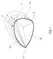
右心室は、左心室の主要筋肉に取り囲まれた薄壁筋肉の「ポケット」である。理論に拘泥する意図はないが、上述の心室圧力の結果として、薄壁右心室および三尖弁輪の一部が、拡張する可能性がある。最初に、三尖弁の弁尖の接合が縮小するが、弁は、必要能力を維持している。その後、三尖弁輪がさらに拡張する場合、弁尖接合が失われ、三尖弁逆流が生ずる。これが機能的三尖弁逆流として知られるものであるが、こう呼ばれる理由は、三尖弁の弁尖が正常なままで残されているためである。問題は、前方と後方部分の拡張した弁輪である。このことは、BexおよびLeCompteにより最初に記載され(Bex and LeCompte(1986)J.Cardiac Surgery1:151−159、「フレキシブルリニアレデューサーを使った三尖弁修復」(Tricuspid Valve Repair Usinga Flexible Linear Reducer))、その後、Dreyfusにより記載された(Dreyfus、et al.(2005)Ann Thoracic Surgery 79:127−32、「2次三尖弁逆流または拡張:どちらを外科的修復の判断基準にすべきか?(Secondary Tricuspid Regurgitation or Dilation:WhichShould Be the Criteria for Surgical Repair?)」)。図1は、Dreyfusから引用したものであるが、三尖弁輪2の拡張、後方弁尖60、前方弁尖62および中隔弁尖64ならびに前/後(A/P)交連3、後/中隔(P/S)交連4および中隔/前(S/A)交連5の相対的位置を図示している。
The right ventricle is a thin-walled muscle “pocket” surrounded by the main muscles of the left ventricle. Without intending to be bound by theory, as a result of the ventricular pressure described above, the thin-walled right ventricle and a portion of the tricuspid annulus can expand. Initially, the leaflet junction of the tricuspid valve is reduced, but the valve maintains the necessary capacity. Later, when the tricuspid annulus further expands, the leaflet junction is lost and tricuspid regurgitation occurs. This is known as functional tricuspid regurgitation, because it is because the leaflets of the tricuspid valve remain normal. The problem is the expanded annulus in the front and rear parts. This was first described by Bex and LeCompte (Bex and LeCompte (1986) J. Cardiac Surgery 1: 151-159, “Tricuspid Valve Repair Using Flexible Linear Reducer”). And later described by Dreyfus (Dreyfus, et al. (2005) Ann Thoracic Surgical 79: 127-32, “Secondary Tricuspid Reflux or Dilation: Which Should Be The Criterion for Surgical Repair? (Secondary Tricuspid Reregulation or Dilation: WhichShould Be the Criter ia for Surgical Repair?) "). FIG. 1 is taken from Dreyfus, but shows an extension of the
上述以外の原因による三尖弁輪の変形もまた、機能的三尖弁逆流につながる可能性がある。 Deformation of the tricuspid annulus due to causes other than those described above can also lead to functional tricuspid regurgitation.
手術に関し今日存在する大きな問題は、三尖弁逆流問題の重症度に対する手術時の認識である。僧帽弁手術直前に、患者は麻酔され、食道に超音波プローブが導入され、僧帽弁および三尖弁逆流が評価される。困難の1つは、麻酔の1つの効果として、三尖弁逆流が大きく抑制される可能性があることである。超音波プローブディスプレイにより外科医が間違った方向に導かれ、三尖弁逆流が無いか、またはごく少ないと判断する可能性がある。不幸にも、後で、手術後に薬剤の効力が切れた場合、三尖弁逆流の本当の程度は、通常、手術中または手術前に認められた程度よりずっと重症になる。残念ながら、三尖弁逆流の患者の再手術死亡率は約30%であるが、重篤な三尖弁逆流を未治療のままで放置するとさらに悪い数字となり、5年患者生存率は約50%である。このことは、現在の症例に比べ、僧帽弁修復を受けているさらに多くの患者が、三尖弁輪縮小術も同時に受けるべきであることを示唆している。僧帽弁修復に付随する三尖弁輪形成縮小術の現状の比率は、約5%および60%の間で変化する。範囲の内の数値の高い側の端では、卓越した研究拠点の外科医が僧帽弁膜症の患者に対し、右心室および三尖弁拡張が重大になる前に早期に手術を行っている。しかし、他の多くの外科医は、手術前または手術中に診断した際のわずかな三尖弁逆流が、麻酔薬が切れた後の回復室で、早くも、重篤になる可能性があることを正しく認識できない。 The major problem that exists today with surgery is the perception during surgery of the severity of the tricuspid regurgitation problem. Immediately prior to mitral valve surgery, the patient is anesthetized, an ultrasound probe is introduced into the esophagus, and mitral and tricuspid regurgitation are assessed. One difficulty is that tricuspid regurgitation can be greatly suppressed as an effect of anesthesia. The ultrasound probe display may guide the surgeon in the wrong direction and determine that there is no or very little tricuspid regurgitation. Unfortunately, if the drug ceases after surgery, the true degree of tricuspid regurgitation is usually much more severe than that observed during or before surgery. Unfortunately, the reoperation mortality rate for patients with tricuspid regurgitation is about 30%, but leaving severe tricuspid regurgitation untreated is worse, and the 5-year patient survival rate is about 50%. %. This suggests that more patients undergoing mitral valve repair should also undergo tricuspid annuloplasty at the same time compared to current cases. The current rate of tricuspid annuloplasty associated with mitral valve repair varies between about 5% and 60%. At the higher end of the range, superior research base surgeons are operating early on patients with mitral valvular disease before the right ventricle and tricuspid valve dilatation become significant. However, many other surgeons find that slight tricuspid regurgitation when diagnosed before or during surgery can be severe as early as in the recovery room after the anesthetic expires. Cannot be recognized correctly.
三尖弁輪の早期修復については、De Vegaにより記述された(De Vega(1972)RevEsp.Cardiol.6:555−557、「Laanulopl astia selective、regulable y permanente」)。ここでは、二重の連続2/0または3/0ポリプロピレン縫合糸を使い、右心室遊離壁に対応する前後弁輪に沿って縫合した。この技術の欠点は、縫合糸が組織から抜けたことや、抜ける傾向が残ることである。しかし、Antunesにより記載された11〜13綿撒糸を使った改良De Vega技術(Antunes(2003)Operative Techniques in Thoracic and Cardiovascular Surgery De Vega 8:169−76、「三尖弁のDe Vega弁輪形成術」)は、手術を複雑で、時間がかかるものにしたが、裂開問題を軽減するように思われる。 Early repair of the tricuspid annulus was described by De Vega (De Vega (1972) RevEsp. Cardiol. 6: 555-557, “Lanopull astial selective, regulatable permanent”). Here, double continuous 2/0 or 3/0 polypropylene sutures were used and sutured along the anteroposterior annulus corresponding to the right ventricular free wall. The disadvantage of this technique is that the suture has left the tissue and has a tendency to come off. However, the modified De Vega technology using the 11-13 pledget described by Antunes (Antunes (2003) Operative Techniques in Thoracic and Cardiovascular Surgical Surgical DeVega 8: 169-76D Surgery ") made the surgery complicated and time consuming, but seems to alleviate the dehiscence problem.
フレキシブル、あるいは、剛体弁形成リングを含む機能的三尖弁逆流を治療する他の方法および装置が使用されてきた。これらの弁形成リングはいずれも、少なくとも1つの問題を示している。埋め込み時、三尖弁形成リングに対していくつかの注意が必要で、特に、房室(AV)結節の埋込縫合は避けなければならない。また、この関連で、既知C形状弁形成リングのギャップは、小さすぎて、埋込縫合をAV結節に侵入させ、心ブロックの原因となる可能性がある。フレキシブルリングを三尖弁輪に埋め込む場合の別の課題には、弁輪上の正しい埋込位置がある。さらに別の課題は、三尖弁輪は、平面と言うより、概ね凹面面になっている事である。機能的三尖弁逆流が進行するにつれ、弁輪は、凹面が少なくなり、よりフラットになる。従って、全くの剛体の三尖弁リングでは、弁輪にうまく適合できない。 Other methods and devices for treating functional tricuspid regurgitation including flexible or rigid annuloplasty rings have been used. All of these annuloplasty rings present at least one problem. At the time of implantation, some attention should be paid to the tricuspid annuloplasty ring, and in particular, implantation sutures in the atrioventricular (AV) node should be avoided. Also in this regard, the gap of the known C-shaped annuloplasty ring is too small and can cause the embedded suture to enter the AV node and cause cardiac block. Another challenge when embedding the flexible ring in the tricuspid annulus is the correct implantation position on the annulus. Yet another problem is that the tricuspid annulus is generally concave rather than flat. As functional tricuspid regurgitation progresses, the annulus becomes less flat and flatter. Therefore, a perfectly rigid tricuspid valve ring cannot fit well into the annulus.
本発明は、上記で考察した1つまたは複数の問題を克服することを目的としている。 The present invention is directed to overcoming one or more of the problems discussed above.
別に指示がなければ、本明細書および請求項で使用される成分、寸法、反応条件、等の量を表す全ての数字は、全ての例において、用語「約」によって修飾されていると理解されるべきである。 Unless otherwise indicated, all numbers representing amounts of ingredients, dimensions, reaction conditions, etc. used in the specification and claims are understood to be modified by the term “about” in all examples. Should be.
本出願および請求項では、明確に別義が指示されていなければ、単数形の使用は、複数形を含む。さらに、「または」の使用は、別義が指示されていなければ、「および/または」を意味する。さらに、用語の「含む(including)」、ならびに他の形、例えば、「含む(includes)」および「含まれる(included)」の使用は、制限を意図するものではない。また、明確に別義が指示されていなければ、「要素」または「成分」等の用語は、1つのユニットを含む「要素」および「成分」ならびに2つ以上のユニットを含む「要素」および「成分」を包含する。 In this application and the claims, the use of the singular includes the plural unless specifically stated otherwise. Further, the use of “or” means “and / or” unless stated otherwise. Furthermore, the use of the term “including”, as well as other forms, such as “includes” and “included”, is not intended to be limiting. Also, unless expressly stated otherwise, terms such as “element” or “component” include “element” and “component” including one unit and “element” and “component” including two or more units. Components ".
図2に、セミフレキシブル弁形成リング10の平面図を示す。図2からわかるように、セミフレキシブル弁形成リング10は、縫合可能材料12によるC形状リングに形成された細長いチューブを含む。本明細書記載の一実施形態では、縫合可能材料は、米国特許第5、674、279号明細書(Wright)に記載のようにしてチューブ形状に熱硬化させた熱硬化性材料の生体適合性リボンであってもよい。本開示は、この参照によりその全体が本明細書に組み込まれる。適切な熱硬化性材料の例は、ポリエーテルテトラフィラート(ポリエステル)である。また、いくつかの実施形態では、他の適切な編んだ、織った、または編んだ生体適合性材料、例えば、ナイロンまたは他の生体適合性材料を含んでもよい。材料は、縫合糸を保持した針、縫合クリップまたは他の類似の固定手段を容易に受け入れるのに適したものでなければならない。また、適切な位置に一旦固定されたら摩滅することなく心臓弁の弁輪上に維持できるものでなければならない。
FIG. 2 shows a plan view of the
Wrightの米国特許第5、674、279号明細書には、熱硬化可能で、溶融可能な繊維チューブから始め、チューブをマンドレル上でスライドさせ、次に、チューブを巻き戻して二重壁チューブを形成する等の編んだリボン材料を作るプロセスが記載されている。この二重壁チューブを加熱ブレードで所望長さに切断する。この切断は、繊維を溶融することにより切断するもので、複数繊維を一緒に溶融し内外壁が融着継ぎ目で結合した融着端を形成する。次に、二重幅チューブをV形状マンドレル上でスリップさせる。このマンドレルは、より高耐熱ポリマーまたは金属で作られ、形成ツールの間で固定され、目的のV形状バンドのV形状開口部のサイズと形を定める形状に作られている。次に、ポリマーを硬化させるのに充分で、かつ、チューブが溶融せずに成形できる温度で、このバンドを熱硬化する。例えば、チューブがポリエステル性である場合は、温度は、100〜110℃の範囲が適切で、加熱時間は約10分でよい。V開口部は、長い縫合糸を使って一緒に縫い合わせ、例えば、図3〜5に示すような4壁チューブを形成できる。 Wright, US Pat. No. 5,674,279, starts with a thermosetable and meltable fiber tube, slides the tube over a mandrel, and then unwinds the tube to create a double-walled tube. A process for making a knitted ribbon material such as forming is described. The double wall tube is cut to the desired length with a heating blade. This cutting is performed by melting the fibers. The plurality of fibers are melted together to form a fusion end where the inner and outer walls are joined by a fusion seam. Next, the double-width tube is slipped on a V-shaped mandrel. The mandrel is made of a higher heat resistant polymer or metal and is shaped between the forming tool and fixed to define the size and shape of the V-shaped opening of the desired V-shaped band. The band is then heat cured at a temperature sufficient to cure the polymer and at which the tube can be molded without melting. For example, if the tube is polyester, the temperature is suitably in the range of 100-110 ° C. and the heating time may be about 10 minutes. The V openings can be stitched together using long sutures to form, for example, a four-wall tube as shown in FIGS.
セミフレキシブル弁形成リング10を弁輪上に設置する際に、種々のマーカを縫合可能材料に設け、外科医を支援することができる。例えば、図2に示す実施形態は、三尖弁輪上に設置することを意図されている。この実施形態では、マーカは、境界マーカ14、および前/後(「A/P」)交連マーカ16を含む。境界マーカ14は、縫合糸または縫合クリップを埋め込むのに使われる針またはクリップが内部補強材またはセミフレキシブル弁形成リング10の動作と干渉しないで配置可能な場所の可視指示を外科医に提供できる。A/P交連マーカは、三尖弁心臓弁のA/P交連に合致するように作られており、外科医が三尖弁輪上の正しい位置にセミフレキシブル弁形成リング10を配置するのを支援する(図9参照)。他の心臓弁を使う実施形態では、他のマーカを提供可能である。さらに、このような実施形態では、セミフレキシブル弁形成リング10は、図2のセミフレキシブル弁形成リング10の実施形態よりもさらに対称的なC形状にすることができる。
In placing the
図2の実施形態では、セミフレキシブル弁形成リング10は、中央部分18、第1の端部分20(前端としても知られる)および第2の端部分22(中隔端としても知られる)を含む。中央部分18は、中央部分18内の長さ方向弧状補強材の固定に使われる半径方向縫合線24、26で規定される。これについては、後述する。
In the embodiment of FIG. 2, the
図3は、図2のセミフレキシブル弁形成リング10の種々の断面部分であり、セミフレキシブル弁形成リング10の内部構造を説明している。中央部分18中の断面部分28(図4も参照)に関しては、上記で参照のWrightの米国特許第5、674、279号明細書に記載されているように、縫合可能材料12は、多くの層を含むことが認められる。縫合可能材料12は、円周方向縫合によりチューブ中で、円周方向縫い目25を形成する。
FIG. 3 shows various cross-sectional portions of the
セミフレキシブル弁形成リング10の中央部分の中に弧状補強材30が配置されている。図示した実施形態中の弧状補強材30は、Carpentier MP35N合金等の生体適合性金属の密巻バネ32を含む。このバネは、0.009〜0.012インチ径ワイヤを使って巻いてもよいが、0.005〜0.020インチの範囲の径の他のワイヤも適している。特定の本明細書記載の実施形態では、バネは、約0.029インチの内径と約0.055インチの外径を有する。他の内外径も本発明の範囲に入る。バネのヘリカルコイルは、内径の内側のバネのキャビティを規定する。補強材30は、長さ方向の圧縮を防ぎ、第1の円周方向部分の軸と半径方向の変形に耐えるように作られている。本明細書で使用する「軸線方向」および「半径方向」は、血液が流入する方向に伸びる弁輪の軸線に対するものである。従って、「軸線方向」の変形は、この軸線に沿った方向、および「半径方向」の変形は、軸線に向かう、または軸線から離れる方向での変形を意味する。「軸線方向と半径方向」の変形は、軸線方向のみの変形、半径方向のみの変形、または軸線方向と半径方向の同時変形を包含することを意図している。補強材ワイヤ34は、バネキャビティ中に軸線方向に受け入れられ、軸線と半径方向の変形に対する抵抗力を与える。補強材ワイヤ34は、例えば、電解腐食を防ぐためにバネと同じ組成の生体適合性金属であってもよい。補強材ワイヤは、前記で定めたように、半径方向の変形に耐える直径でなければならない。セミフレキシブル弁形成リングが機能的三尖弁逆流の治療用の三尖弁に使われる場合の例としては、約0.028インチの直径のMP35N合金を使って良い結果が得られ、通常、0.015〜0.050インチの範囲(所望の剛性およびリングサイズに応じて)が利用可能である。
An
補強材ワイヤ34は、補強材の各端にある端キャップ36により、密巻バネ32内に長手方向に固定される。第2の端部分22に近接している端キャップ36は、図3の破断部分38に示されている。図には示していないが、同じ端キャップ36が、半径方向縫合線24に隣接した第1の端部分20の近くにある。各端キャップ36は、丸みを付けるか、または面取りして、全てのシャープエッジを除去し、さらに半球状にしてもよい。セミフレキシブル弁形成リング10が図2と図3に示すように形成される場合、端キャップは、補強材が縫合可能材料12から突き出るのを防ぐように作られている。図示した実施形態では、端キャップは、約0.046インチの外径を有する。補強材30は、A/P交連マーカ16、およびセミフレキシブル弁形成リング10を拡張前の健康な三尖弁輪(「拡張前弁輪」)の少なくとも後方部分に適合させるように選択される後方半径42を有する半径方向縫合線26の間の後方部分40を含む。補強材30は、さらにA/P交連マーカ16および半径方向縫合線24の間に広がる前方部分44を含む。部分44は、前方半径46を有し、これは、後方半径42より大きく、セミフレキシブル弁形成リング10が、三尖弁の弁輪に作動的に取り付けられ、前方半径が拡張前弁輪の少なくとも前方部分に適合するように選択される。密巻バネ32は、シリコンゴムチューブ47の中に収容される。
The reinforcing
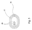
第1の端部分20および第2の端部分22は、補強材を含まず、その結果、第1と第2の端部分は、下記に説明するように軸線方向および半径方向に変形可能である。本明細書で図示されている実施形態では、X線マーカ48が、チューブ内、および第1と第2の端20、22のそれぞれに配置されている。X線マーカ48は、第1と第2の端の半径方向または軸線方向の変形を大きく抑制しないという意味で非構造的である。図示されている実施形態では、X線マーカ48は、タングステンおよびバリウム硫酸塩を混合した0.020インチシリコーンゴムバンドである。再度図3に関して、X線マーカ48は、縫合可能材料12から引き出した縫合可能材料12の組紐50を介してX線マーカ48を取り付けることにより、第1と第2の端部分20、22内で固定される。
The
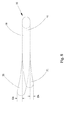
縫合可能材料のチューブ12は、前述したWrightの米国特許第5、674、279号明細書に記載されている方法で形成可能である。縫合可能材料12を、V字断面を有する長さ部分に形成し、補強材30を、V字の底部に配置し、補強材30の周りの周方向に間隔を開けて配置したタックステッチ52(図3参照)により適切な位置に保持される。X線マーカ48は、同様に、Vの底部に配置され、上述のように、引き出した縫合可能材料12の組紐50を介してX線マーカ48を取り付けることにより固定される。その後、円周方向縫い目25が形成され、V断面がチューブ中に形成される。境界マーカ14およびA/P交連マーカ16が、縫合糸として付加される。さらに、半径方向縫合線24、26が、周方向に追加され、中央部分内に弧状補強材を限定することができる。次に、組み上げたセミフレキシブル弁形成リング10を、熱硬化して、図2、図3および図6〜図10に示すような形状に維持することが好ましい。図6に関し、セミフレキシブル弁形成リング10を熱硬化して、図のように、選択した外径ODおよび選択した内径IDを持たせる。これにより、図6に示されるような、公称寸法NSの大きさのセミフレキシブル弁形成リング10が得られる。熱硬化した場合、セミフレキシブル弁形成リング10は、さらに第1の端部分20と第2の端部分22の間にギャップGを保持する。このギャップGは、弁形成リングの公称寸法NSの約50%を超える長さを有する。一実施形態では、ギャップGは、公称寸法NSの約60%の長さを有することができる。このサイズは、セミフレキシブル弁形成リング10の埋込の間に房室(AV)結節を損傷する危険性を最小限にするように選択される。図7に関して、熱硬化した場合には、セミフレキシブル弁形成リング10は、弧状補強材30で規定される平面51の周りで実質的に平面である。
The
図8に関して、セミフレキシブル弁形成リング10の中央部分18は、実質的に弧状補強材30の平面51内に留まることが意図されている。第1と第2の端部分20、22は、図8に示すように、軸線方向のどちらの方にも実質的に変形が自由である。図には示していないが、第1と第2の端部分20、22は、半径方向にも変形可能である。
With respect to FIG. 8, the
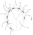
図9は、三尖弁を露出させるために右心房壁を切開し、後退させ、心臓の三尖弁に作動的に取り付けたセミフレキシブル弁形成リング10を示す。セミフレキシブル弁形成リング10は、拡張前または正常に近い状態に対し三尖弁輪を適合させるために寸法と位置を定めている。後方部分40は、後方弁尖60の基部で三尖弁輪に合わせている。中央部分18の前方部分44は、前方弁尖62の基部で、三尖弁輪の前方部分の円周方向長さの約1/3に覆いかぶさる。前端とも呼ばれる第1の端部分20は、同様に、前方弁輪に固定される。中隔端としても知られる第2の端部分22は、中隔弁尖64の基部で、三尖弁輪の中隔部分に取り付けられる。図9で認められるように、セミフレキシブル弁形成リング10を三尖弁輪に固定するのに8つの縫合糸66のみが必要である。患者の解剖学的形態に応じて、1つまたは2つまたは3つまでも少ないまたは多い縫合糸を使うことができる。いかなる場合でも、この数は、弁形成リングの三尖弁への埋め込みの先行技術で必要な12〜14縫合糸より少ない。縫合糸の数を減らすことにより、約15分のオーダーでより素早くセミフレキシブル弁形成リング10を埋め込むことを可能とするが、これは先行技術の装置に比べかなり早い。
FIG. 9 shows a
図10は、ホルダー70に取り付けた図2のセミフレキシブル弁形成リング10の平面図である。図10は、さらに、三尖弁輪に弁形成リングを埋め込むための8つの取り付け縫合糸の好ましい位置を図示している。
10 is a plan view of the
セミフレキシブル弁形成リング10の中央部分40は、三尖弁輪の取り付け部分を実質的に平面形状に維持し、三尖弁輪拡張領域の「ハンモック」効果を防ぐ。一方で、フレキシブルな第1と第2端部分は、三尖弁輪に対し軸線方向および半径方向に変形可能で、取り付けた縫合糸と弁輪組織の応力を実質的に除去するが、この場合も、三尖弁の正常な機能と実質的に干渉することなく、三尖弁輪の拡張を制御している。言い換えれば、フレキシブル端部分は、矯正された、または非拡張弁輪を有する三尖弁の正常な動作の実効性を阻害しない。
The
種々の本開示実施形態は、あたかも、各従属請求項が、先行従属請求項ならびに独立請求項のそれぞれの制限を組み込んだ複数の従属請求項であるかのように、請求項中で列挙される種々の要素の組み合わせを含むことができる。このような組み合わせは、明示的に本開示の範囲内にある。 Various disclosed embodiments are recited in the claims as if each dependent claim was a plurality of dependent claims incorporating the respective limitations of the preceding dependent claim as well as the independent claims. A combination of various elements can be included. Such combinations are explicitly within the scope of this disclosure.
本発明では、関連する多くの実施形態を具体的に示し説明してきたが、本明細書で開示されている種々の実施形態に対し、本発明の趣旨と範囲を逸脱することなく形態および詳細に対する変更を行うことができ、さらに本明細書で開示の種々の実施形態は、請求項の範囲を限定するものとする意図はないことは、当業者なら理解できる。本明細書に引用された全ての文献および付属書は、この参照によりその全体が組み込まれる。 While the invention has been illustrated and described in terms of many related embodiments, it is to be understood that the invention is not limited to the various embodiments disclosed herein without departing from the spirit and scope of the invention. It will be appreciated by those skilled in the art that modifications may be made and that the various embodiments disclosed herein are not intended to limit the scope of the claims. All references and appendices cited herein are incorporated in their entirety by this reference.
Claims (14)
中央部分ならびに第1および第2の端部分を含む細長い縫合可能材料チューブと、
前記チューブの中央部分に収容され、該中央部分の長さにわたって延びる弧状補強材であって、前記チューブに対する補強材の円周方向の移動を防ぐために、前記中央部分内に周方向の移動を拘束されている弧状補強材と、を備え、
前記チューブの第1と第2の端部分に補強材が無く、前記第1と第2の端は軸線方向に変形可能であり、
前記弧状補強材は、密巻コイルスプリングと該密巻コイルスプリングのバネキャビティ内に収容された補強ワイヤとを備え、
前記弧状補強材は、該補強ワイヤを前記弧状補強材の各端の端キャップによって密巻コイルスプリング内に長手方向に固定するように、構成されている、
ことを特徴とする弁形成リング。 Anterior leaflet, posterior leaflet and septal valve connected by anterior / posterior commissure (A / P commissure), posterior / septal commissure (P / S commissure) and septum / anterior commissure (S / A commissure), respectively An annuloplasty ring for attachment to an annulus of a tricuspid valve including a cusp,
An elongate suture material tube including a central portion and first and second end portions;
Housed in a central portion of said tube, a arcuate reinforcement extending over the length of the central portion, in order to prevent the movement of circumferential reinforcement for said tube, restraining the movement of the circumferential direction in the center in section Arc-shaped reinforcing material, and
No reinforcements in the first and second end portions of said tube, said first and second ends is Ri deformable der axially
The arc-shaped reinforcing member includes a closely wound coil spring and a reinforcing wire accommodated in a spring cavity of the closely wound coil spring,
The arc-shaped reinforcing member is configured to fix the reinforcing wire in the longitudinal direction in the closely wound coil spring by an end cap at each end of the arc-shaped reinforcing member.
An annuloplasty ring characterized by that.
請求項1に記載の弁形成リング。 An annuloplasty ring is operatively attached to the annulus of the tricuspid valve, the central portion of which is formed to extend from the periphery of the S / P commissure to the A / P commissure.
An annuloplasty ring according to claim 1.
請求項1に記載の弁形成リング。 The arcuate reinforcement includes a rear portion having a rear radius and a front portion having a front radius, the front radius being greater than the rear radius;
An annuloplasty ring according to claim 1.
請求項3に記載の弁形成リング。 The posterior radius and the anterior radius are such that the annuloplasty ring is operatively attached to the annulus of the tricuspid valve, the posterior radius is adapted to at least the posterior portion of the annulus before expansion, and the anterior radius is Selected to fit at least a portion of the front portion of the annulus of the condition,
An annuloplasty ring according to claim 3.
請求項1に記載の弁形成リング。 When the first and second ends are sufficiently deformable in the axial direction so that the annuloplasty ring is operatively attached to the annulus of the tricuspid valve, the first and second ends are arcuate. Easily deviate from the plane defined by the stiffener and can conform to the tricuspid valve anatomy without substantially interfering with normal operation,
An annuloplasty ring according to claim 1.
請求項1に記載の弁形成リング。 The elongate stitchable material tube comprises a knitted thermoset material that thermosets into a C shape in a plane defined by an arcuate reinforcement.
An annuloplasty ring according to claim 1.
請求項6に記載の弁形成リング。 Defining a gap in which the opening of C has a length greater than about 50% of the nominal dimension of the annuloplasty ring;
An annuloplasty ring according to claim 6.
請求項7に記載の弁形成リング。 The gap is about 60% of the nominal dimension,
An annuloplasty ring according to claim 7.
請求項1に記載の弁形成リング。 The arc-shaped reinforcement is constrained in circumferential movement within the central portion by sutures at each end of the arc-shaped reinforcement,
An annuloplasty ring according to claim 1.
請求項1に記載の弁形成リング。 Further comprising an X-ray marker at each first and second end portion;
An annuloplasty ring according to claim 1.
請求項10に記載の弁形成リング。 The X-ray marker is easily deformable in the axial and radial directions;
An annuloplasty ring according to claim 10.
請求項1に記載の弁形成リング。 The first and second end portions are easily deformable in the axial and radial directions;
An annuloplasty ring according to claim 1.
請求項1に記載の弁形成リング。 Further comprising no more than about 11 attachment sutures spaced circumferentially;
An annuloplasty ring according to claim 1.
請求項8に記載の弁形成リング。 An arcuate reinforcement is secured to the sutureable material by a suture at each end of the arcuate reinforcement;
An annuloplasty ring according to claim 8.
Applications Claiming Priority (5)
| Application Number | Priority Date | Filing Date | Title |
|---|---|---|---|
| US30115810P | 2010-02-03 | 2010-02-03 | |
| US61/301,158 | 2010-02-03 | ||
| US30153210P | 2010-02-04 | 2010-02-04 | |
| US61/301,532 | 2010-02-04 | ||
| PCT/US2011/023386 WO2011097251A1 (en) | 2010-02-03 | 2011-02-01 | Semi-flexible annuloplasty ring |
Publications (3)
| Publication Number | Publication Date |
|---|---|
| JP2013518671A JP2013518671A (en) | 2013-05-23 |
| JP2013518671A5 JP2013518671A5 (en) | 2014-03-20 |
| JP5778183B2 true JP5778183B2 (en) | 2015-09-16 |
Family
ID=44355742
Family Applications (1)
| Application Number | Title | Priority Date | Filing Date |
|---|---|---|---|
| JP2012552041A Active JP5778183B2 (en) | 2010-02-03 | 2011-02-01 | Semi-flexible annuloplasty ring |
Country Status (5)
| Country | Link |
|---|---|
| US (2) | US10932907B2 (en) |
| EP (1) | EP2531143B1 (en) |
| JP (1) | JP5778183B2 (en) |
| CN (1) | CN102985031B (en) |
| WO (1) | WO2011097251A1 (en) |
Families Citing this family (94)
| Publication number | Priority date | Publication date | Assignee | Title |
|---|---|---|---|---|
| WO2006097931A2 (en) | 2005-03-17 | 2006-09-21 | Valtech Cardio, Ltd. | Mitral valve treatment techniques |
| US8951285B2 (en) | 2005-07-05 | 2015-02-10 | Mitralign, Inc. | Tissue anchor, anchoring system and methods of using the same |
| JP2009539422A (en) * | 2006-06-02 | 2009-11-19 | メドトロニック・インコーポレーテッド | Annuloplasty ring and plastic surgery |
| US9883943B2 (en) | 2006-12-05 | 2018-02-06 | Valtech Cardio, Ltd. | Implantation of repair devices in the heart |
| US11259924B2 (en) | 2006-12-05 | 2022-03-01 | Valtech Cardio Ltd. | Implantation of repair devices in the heart |
| US8926695B2 (en) | 2006-12-05 | 2015-01-06 | Valtech Cardio, Ltd. | Segmented ring placement |
| US11660190B2 (en) | 2007-03-13 | 2023-05-30 | Edwards Lifesciences Corporation | Tissue anchors, systems and methods, and devices |
| CN103393485B (en) | 2007-09-07 | 2016-08-10 | 爱德华兹生命科学公司 | For carrying the travel(l)ing rest of annuloplasty ring |
| US8382829B1 (en) | 2008-03-10 | 2013-02-26 | Mitralign, Inc. | Method to reduce mitral regurgitation by cinching the commissure of the mitral valve |
| US9192472B2 (en) | 2008-06-16 | 2015-11-24 | Valtec Cardio, Ltd. | Annuloplasty devices and methods of delivery therefor |
| US8545553B2 (en) | 2009-05-04 | 2013-10-01 | Valtech Cardio, Ltd. | Over-wire rotation tool |
| WO2010073246A2 (en) | 2008-12-22 | 2010-07-01 | Valtech Cardio, Ltd. | Adjustable annuloplasty devices and adjustment mechanisms therefor |
| US9011530B2 (en) | 2008-12-22 | 2015-04-21 | Valtech Cardio, Ltd. | Partially-adjustable annuloplasty structure |
| US10517719B2 (en) | 2008-12-22 | 2019-12-31 | Valtech Cardio, Ltd. | Implantation of repair devices in the heart |
| US8715342B2 (en) | 2009-05-07 | 2014-05-06 | Valtech Cardio, Ltd. | Annuloplasty ring with intra-ring anchoring |
| US8241351B2 (en) | 2008-12-22 | 2012-08-14 | Valtech Cardio, Ltd. | Adjustable partial annuloplasty ring and mechanism therefor |
| EP2381895B1 (en) * | 2008-12-31 | 2021-07-07 | Medtronic, Inc. | Semi-rigid annuloplasty ring and band and method of making an annuloplasty ring |
| US8353956B2 (en) | 2009-02-17 | 2013-01-15 | Valtech Cardio, Ltd. | Actively-engageable movement-restriction mechanism for use with an annuloplasty structure |
| US9968452B2 (en) | 2009-05-04 | 2018-05-15 | Valtech Cardio, Ltd. | Annuloplasty ring delivery cathethers |
| US9180007B2 (en) | 2009-10-29 | 2015-11-10 | Valtech Cardio, Ltd. | Apparatus and method for guide-wire based advancement of an adjustable implant |
| US9011520B2 (en) | 2009-10-29 | 2015-04-21 | Valtech Cardio, Ltd. | Tissue anchor for annuloplasty device |
| US10098737B2 (en) | 2009-10-29 | 2018-10-16 | Valtech Cardio, Ltd. | Tissue anchor for annuloplasty device |
| WO2011067770A1 (en) | 2009-12-02 | 2011-06-09 | Valtech Cardio, Ltd. | Delivery tool for implantation of spool assembly coupled to a helical anchor |
| US8870950B2 (en) | 2009-12-08 | 2014-10-28 | Mitral Tech Ltd. | Rotation-based anchoring of an implant |
| US8579964B2 (en) | 2010-05-05 | 2013-11-12 | Neovasc Inc. | Transcatheter mitral valve prosthesis |
| US11653910B2 (en) | 2010-07-21 | 2023-05-23 | Cardiovalve Ltd. | Helical anchor implantation |
| US8932350B2 (en) | 2010-11-30 | 2015-01-13 | Edwards Lifesciences Corporation | Reduced dehiscence annuloplasty ring |
| US9554897B2 (en) | 2011-04-28 | 2017-01-31 | Neovasc Tiara Inc. | Methods and apparatus for engaging a valve prosthesis with tissue |
| US9308087B2 (en) | 2011-04-28 | 2016-04-12 | Neovasc Tiara Inc. | Sequentially deployed transcatheter mitral valve prosthesis |
| US9402721B2 (en) | 2011-06-01 | 2016-08-02 | Valcare, Inc. | Percutaneous transcatheter repair of heart valves via trans-apical access |
| US10792152B2 (en) | 2011-06-23 | 2020-10-06 | Valtech Cardio, Ltd. | Closed band for percutaneous annuloplasty |
| US8858623B2 (en) * | 2011-11-04 | 2014-10-14 | Valtech Cardio, Ltd. | Implant having multiple rotational assemblies |
| EP3656434B1 (en) | 2011-11-08 | 2021-10-20 | Valtech Cardio, Ltd. | Controlled steering functionality for implant-delivery tool |
| WO2013130641A1 (en) | 2012-02-29 | 2013-09-06 | Valcare, Inc. | Percutaneous annuloplasty system with anterior-posterior adjustment |
| US9180008B2 (en) | 2012-02-29 | 2015-11-10 | Valcare, Inc. | Methods, devices, and systems for percutaneously anchoring annuloplasty rings |
| US9345573B2 (en) | 2012-05-30 | 2016-05-24 | Neovasc Tiara Inc. | Methods and apparatus for loading a prosthesis onto a delivery system |
| WO2014052818A1 (en) | 2012-09-29 | 2014-04-03 | Mitralign, Inc. | Plication lock delivery system and method of use thereof |
| EP3730084A1 (en) | 2012-10-23 | 2020-10-28 | Valtech Cardio, Ltd. | Controlled steering functionality for implant-delivery tool |
| WO2014064695A2 (en) | 2012-10-23 | 2014-05-01 | Valtech Cardio, Ltd. | Percutaneous tissue anchor techniques |
| WO2014087402A1 (en) | 2012-12-06 | 2014-06-12 | Valtech Cardio, Ltd. | Techniques for guide-wire based advancement of a tool |
| US20150351906A1 (en) | 2013-01-24 | 2015-12-10 | Mitraltech Ltd. | Ventricularly-anchored prosthetic valves |
| US9724084B2 (en) | 2013-02-26 | 2017-08-08 | Mitralign, Inc. | Devices and methods for percutaneous tricuspid valve repair |
| US10449333B2 (en) | 2013-03-14 | 2019-10-22 | Valtech Cardio, Ltd. | Guidewire feeder |
| EP2967700B1 (en) | 2013-03-15 | 2020-11-25 | Valcare, Inc. | Systems for delivery of annuloplasty rings |
| CN105283214B (en) | 2013-03-15 | 2018-10-16 | 北京泰德制药股份有限公司 | Translate conduit, system and its application method |
| US9572665B2 (en) | 2013-04-04 | 2017-02-21 | Neovasc Tiara Inc. | Methods and apparatus for delivering a prosthetic valve to a beating heart |
| FR3004335A1 (en) * | 2013-04-11 | 2014-10-17 | Cormove | PARTIALLY DEFORMABLE ANNULOPLASTY PROSTHESIS |
| AU2014268631B2 (en) | 2013-05-20 | 2019-08-01 | Twelve, Inc. | Implantable heart valve devices, mitral valve repair devices and associated systems and methods |
| US10813751B2 (en) | 2013-05-22 | 2020-10-27 | Valcare, Inc. | Transcatheter prosthetic valve for mitral or tricuspid valve replacement |
| US20160120642A1 (en) | 2013-05-24 | 2016-05-05 | Valcare, Inc. | Heart and peripheral vascular valve replacement in conjunction with a support ring |
| WO2014210600A2 (en) | 2013-06-28 | 2014-12-31 | Valcare, Inc. | Device, system, and method to secure an article to a tissue |
| CN104010593B (en) * | 2013-07-29 | 2016-05-25 | 金仕生物科技(常熟)有限公司 | Artificial heart valve forming ring |
| US10070857B2 (en) | 2013-08-31 | 2018-09-11 | Mitralign, Inc. | Devices and methods for locating and implanting tissue anchors at mitral valve commissure |
| US10299793B2 (en) | 2013-10-23 | 2019-05-28 | Valtech Cardio, Ltd. | Anchor magazine |
| EP3788987A1 (en) * | 2013-11-15 | 2021-03-10 | Guy's And St. Thomas' NHS Foundation Trust | Information markers for heart prostheses |
| US9610162B2 (en) | 2013-12-26 | 2017-04-04 | Valtech Cardio, Ltd. | Implantation of flexible implant |
| WO2016059639A1 (en) | 2014-10-14 | 2016-04-21 | Valtech Cardio Ltd. | Leaflet-restraining techniques |
| WO2016125160A1 (en) | 2015-02-05 | 2016-08-11 | Mitraltech Ltd. | Prosthetic valve with axially-sliding frames |
| US20160256269A1 (en) | 2015-03-05 | 2016-09-08 | Mitralign, Inc. | Devices for treating paravalvular leakage and methods use thereof |
| CN114515173A (en) | 2015-04-30 | 2022-05-20 | 瓦尔泰克卡迪欧有限公司 | Valvuloplasty techniques |
| US10314707B2 (en) * | 2015-06-09 | 2019-06-11 | Edwards Lifesciences, Llc | Asymmetric mitral annuloplasty band |
| JP7111610B2 (en) | 2015-08-21 | 2022-08-02 | トゥエルヴ, インコーポレイテッド | Implantable Heart Valve Devices, Mitral Valve Repair Devices, and Related Systems and Methods |
| WO2017117370A2 (en) | 2015-12-30 | 2017-07-06 | Mitralign, Inc. | System and method for reducing tricuspid regurgitation |
| US10751182B2 (en) | 2015-12-30 | 2020-08-25 | Edwards Lifesciences Corporation | System and method for reshaping right heart |
| CA3007670A1 (en) | 2016-01-29 | 2017-08-03 | Neovasc Tiara Inc. | Prosthetic valve for avoiding obstruction of outflow |
| US10531866B2 (en) | 2016-02-16 | 2020-01-14 | Cardiovalve Ltd. | Techniques for providing a replacement valve and transseptal communication |
| GB2548891B (en) | 2016-03-31 | 2018-07-04 | I Birdi Ltd | A prosthetic device for mitral valve repair |
| US10702274B2 (en) | 2016-05-26 | 2020-07-07 | Edwards Lifesciences Corporation | Method and system for closing left atrial appendage |
| GB201611910D0 (en) | 2016-07-08 | 2016-08-24 | Valtech Cardio Ltd | Adjustable annuloplasty device with alternating peaks and troughs |
| EP3848003A1 (en) | 2016-08-10 | 2021-07-14 | Cardiovalve Ltd. | Prosthetic valve with concentric frames |
| CN107753153B (en) | 2016-08-15 | 2022-05-31 | 沃卡尔有限公司 | Device and method for treating heart valve insufficiency |
| WO2018090148A1 (en) | 2016-11-21 | 2018-05-24 | Neovasc Tiara Inc. | Methods and systems for rapid retraction of a transcatheter heart valve delivery system |
| CN108618871A (en) | 2017-03-17 | 2018-10-09 | 沃卡尔有限公司 | Bicuspid valve with multi-direction anchor portion or tricuspid valve repair system |
| CN106821548B (en) * | 2017-04-01 | 2020-11-03 | 上海纽脉医疗科技有限公司 | Transcatheter artificial mitral valve annuloplasty ring device and system |
| US11045627B2 (en) | 2017-04-18 | 2021-06-29 | Edwards Lifesciences Corporation | Catheter system with linear actuation control mechanism |
| RU2738014C1 (en) * | 2017-07-18 | 2020-12-07 | Кефалиос С.А.С. | Adjustable percutaneous devices for annuloplasty, delivering systems, method for percutaneous unfolding of annuloplasty device and method implemented by means of one or more treatment devices |
| CA3073834A1 (en) | 2017-08-25 | 2019-02-28 | Neovasc Tiara Inc. | Sequentially deployed transcatheter mitral valve prosthesis |
| US10835221B2 (en) | 2017-11-02 | 2020-11-17 | Valtech Cardio, Ltd. | Implant-cinching devices and systems |
| US11135062B2 (en) | 2017-11-20 | 2021-10-05 | Valtech Cardio Ltd. | Cinching of dilated heart muscle |
| CN116531147A (en) | 2018-01-24 | 2023-08-04 | 爱德华兹生命科学创新(以色列)有限公司 | Contraction of annuloplasty structures |
| EP3743014B1 (en) | 2018-01-26 | 2023-07-19 | Edwards Lifesciences Innovation (Israel) Ltd. | Techniques for facilitating heart valve tethering and chord replacement |
| CR20210020A (en) | 2018-07-12 | 2021-07-21 | Valtech Cardio Ltd | Annuloplasty systems and locking tools therefor |
| CA3104687A1 (en) | 2018-07-30 | 2020-02-06 | Edwards Lifesciences Corporation | Minimally-invasive low strain annuloplasty ring |
| EP3876870B1 (en) | 2018-11-08 | 2023-12-20 | Neovasc Tiara Inc. | Ventricular deployment of a transcatheter mitral valve prosthesis |
| EP3890658A4 (en) | 2018-12-03 | 2022-12-21 | Valcare, Inc. | Stabilizing and adjusting tool for controlling a minimally invasive mitral / tricuspid valve repair system |
| CN109662805B (en) * | 2019-01-18 | 2024-02-13 | 西安增材制造国家研究院有限公司 | Tricuspid annuloplasty ring and method of making same |
| CA3135753C (en) | 2019-04-01 | 2023-10-24 | Neovasc Tiara Inc. | Controllably deployable prosthetic valve |
| US11491006B2 (en) | 2019-04-10 | 2022-11-08 | Neovasc Tiara Inc. | Prosthetic valve with natural blood flow |
| AU2020279750B2 (en) | 2019-05-20 | 2023-07-13 | Neovasc Tiara Inc. | Introducer with hemostasis mechanism |
| EP3986332A4 (en) | 2019-06-20 | 2023-07-19 | Neovasc Tiara Inc. | Low profile prosthetic mitral valve |
| EP3998995A4 (en) | 2019-07-15 | 2023-08-23 | ValCare, Inc. | Transcatheter bio-prosthesis member and support structure |
| CA3142906A1 (en) | 2019-10-29 | 2021-05-06 | Valtech Cardio, Ltd. | Annuloplasty and tissue anchor technologies |
| WO2022015966A1 (en) * | 2020-07-15 | 2022-01-20 | The Board Of Trustees Of The Leland Stanford Junior University | Selectively flexible mitral annuloplasty devices for optimal annulus dynamics and biomechanics |
| US11723773B2 (en) * | 2021-06-15 | 2023-08-15 | “National Research Cardiac Surgery Center” Npjsc | Surgery for correcting tricuspid valve regurgitation |
Family Cites Families (17)
| Publication number | Priority date | Publication date | Assignee | Title |
|---|---|---|---|---|
| FR2306671A1 (en) * | 1975-04-11 | 1976-11-05 | Rhone Poulenc Ind | VALVULAR IMPLANT |
| WO1993015690A2 (en) * | 1992-01-27 | 1993-08-19 | Medtronic, Inc. | Annuloplasty and suture rings |
| WO1997019655A1 (en) * | 1995-12-01 | 1997-06-05 | Medtronic, Inc. | Annuloplasty prosthesis |
| DE19910233A1 (en) * | 1999-03-09 | 2000-09-21 | Jostra Medizintechnik Ag | Anuloplasty prosthesis |
| US6187040B1 (en) * | 1999-05-03 | 2001-02-13 | John T. M. Wright | Mitral and tricuspid annuloplasty rings |
| US6786924B2 (en) * | 2001-03-15 | 2004-09-07 | Medtronic, Inc. | Annuloplasty band and method |
| US6955689B2 (en) * | 2001-03-15 | 2005-10-18 | Medtronic, Inc. | Annuloplasty band and method |
| US6908482B2 (en) * | 2001-08-28 | 2005-06-21 | Edwards Lifesciences Corporation | Three-dimensional annuloplasty ring and template |
| US20090088838A1 (en) * | 2006-05-12 | 2009-04-02 | Shaolian Samuel M | Adjustable annuloplasty ring and activation system |
| US20070276478A1 (en) * | 2006-05-12 | 2007-11-29 | Micardia Corporation | Intraoperative and post-operative adjustment of an annuloplasty ring |
| US7879087B2 (en) * | 2006-10-06 | 2011-02-01 | Edwards Lifesciences Corporation | Mitral and tricuspid annuloplasty rings |
| EP3488822B1 (en) * | 2007-01-26 | 2020-10-21 | Medtronic, Inc. | Annuloplasty device for tricuspid valve repair |
| US7993395B2 (en) * | 2008-01-25 | 2011-08-09 | Medtronic, Inc. | Set of annuloplasty devices with varying anterior-posterior ratios and related methods |
| US20090287303A1 (en) * | 2008-05-13 | 2009-11-19 | Edwards Lifesciences Corporation | Physiologically harmonized tricuspid annuloplasty ring |
| EP2381895B1 (en) * | 2008-12-31 | 2021-07-07 | Medtronic, Inc. | Semi-rigid annuloplasty ring and band and method of making an annuloplasty ring |
| US20110160849A1 (en) * | 2009-12-22 | 2011-06-30 | Edwards Lifesciences Corporation | Bimodal tricuspid annuloplasty ring |
| US8932350B2 (en) * | 2010-11-30 | 2015-01-13 | Edwards Lifesciences Corporation | Reduced dehiscence annuloplasty ring |
-
2011
- 2011-02-01 JP JP2012552041A patent/JP5778183B2/en active Active
- 2011-02-01 US US13/576,982 patent/US10932907B2/en active Active
- 2011-02-01 WO PCT/US2011/023386 patent/WO2011097251A1/en active Application Filing
- 2011-02-01 EP EP11740273.5A patent/EP2531143B1/en active Active
- 2011-02-01 CN CN201180015528.0A patent/CN102985031B/en active Active
-
2021
- 2021-02-05 US US17/169,068 patent/US20210161665A1/en active Pending
Also Published As
| Publication number | Publication date |
|---|---|
| WO2011097251A1 (en) | 2011-08-11 |
| US20130204361A1 (en) | 2013-08-08 |
| EP2531143A1 (en) | 2012-12-12 |
| CN102985031A (en) | 2013-03-20 |
| US20210161665A1 (en) | 2021-06-03 |
| EP2531143B1 (en) | 2018-01-17 |
| CN102985031B (en) | 2015-09-30 |
| EP2531143A4 (en) | 2015-12-02 |
| US10932907B2 (en) | 2021-03-02 |
| JP2013518671A (en) | 2013-05-23 |
Similar Documents
| Publication | Publication Date | Title |
|---|---|---|
| JP5778183B2 (en) | Semi-flexible annuloplasty ring | |
| US11364117B2 (en) | Braid connections for prosthetic heart valves | |
| JP7055992B2 (en) | Heart valve repair device and its implantation method | |
| US10398547B2 (en) | Implant with anchoring device for heart valve disease | |
| US10004598B2 (en) | Implantable device for use in the human and/or animal body to replace an organ valve | |
| JP6441297B2 (en) | Stent and stent graft | |
| US9414919B2 (en) | Semi-rigid annuloplasty ring and band | |
| US20120078360A1 (en) | Prosthetic devices, systems and methods for replacing heart valves | |
| US9526612B2 (en) | Transcatheter valve replacement | |
| CN108348321B (en) | Heart valve | |
| BR112020016300A2 (en) | HEART VALVE FITTING DEVICES AND SYSTEMS | |
| JP2019524378A (en) | Heart valve docking coil and system | |
| US20070203391A1 (en) | System for Treating Mitral Valve Regurgitation | |
| US20070078297A1 (en) | Device for Treating Mitral Valve Regurgitation | |
| CN115515533A (en) | High flexibility implant catheter with low compression | |
| EP3269328A2 (en) | Cardiac valve implant | |
| CN105263423A (en) | Percutaneous valve repair by reshaping and resizing right ventricle | |
| JP2023059960A (en) | Asymmetric mitral annuloplasty band | |
| JP2004528885A (en) | Ring forming band and method | |
| CN209377809U (en) | A kind of heart valve prosthesis prosthese and its bracket | |
| EP4003233A1 (en) | Tethering system for a prosthetic heart valve | |
| CN113952082A (en) | Anti-backflow multifunctional heart valve prosthesis | |
| CN114948345A (en) | Heart valve positioning device, heart valve replacement assembly and implantation method | |
| JP2024508254A (en) | double frame replacement heart valve | |
| CN117136038A (en) | Double frame replacement heart valve |
Legal Events
| Date | Code | Title | Description |
|---|---|---|---|
| A521 | Request for written amendment filed |
Free format text: JAPANESE INTERMEDIATE CODE: A523 Effective date: 20140130 |
|
| A621 | Written request for application examination |
Free format text: JAPANESE INTERMEDIATE CODE: A621 Effective date: 20140130 |
|
| A977 | Report on retrieval |
Free format text: JAPANESE INTERMEDIATE CODE: A971007 Effective date: 20141017 |
|
| A131 | Notification of reasons for refusal |
Free format text: JAPANESE INTERMEDIATE CODE: A131 Effective date: 20141029 |
|
| A521 | Request for written amendment filed |
Free format text: JAPANESE INTERMEDIATE CODE: A523 Effective date: 20150129 |
|
| TRDD | Decision of grant or rejection written | ||
| A01 | Written decision to grant a patent or to grant a registration (utility model) |
Free format text: JAPANESE INTERMEDIATE CODE: A01 Effective date: 20150608 |
|
| A61 | First payment of annual fees (during grant procedure) |
Free format text: JAPANESE INTERMEDIATE CODE: A61 Effective date: 20150708 |
|
| R150 | Certificate of patent or registration of utility model |
Ref document number: 5778183 Country of ref document: JP Free format text: JAPANESE INTERMEDIATE CODE: R150 |
|
| R250 | Receipt of annual fees |
Free format text: JAPANESE INTERMEDIATE CODE: R250 |
|
| R250 | Receipt of annual fees |
Free format text: JAPANESE INTERMEDIATE CODE: R250 |
|
| R250 | Receipt of annual fees |
Free format text: JAPANESE INTERMEDIATE CODE: R250 |
|
| R250 | Receipt of annual fees |
Free format text: JAPANESE INTERMEDIATE CODE: R250 |
|
| R250 | Receipt of annual fees |
Free format text: JAPANESE INTERMEDIATE CODE: R250 |
|
| R250 | Receipt of annual fees |
Free format text: JAPANESE INTERMEDIATE CODE: R250 |