EP3595531B1 - X-ray imaging apparatus and patient support - Google Patents
X-ray imaging apparatus and patient support Download PDFInfo
- Publication number
- EP3595531B1 EP3595531B1 EP18767424.7A EP18767424A EP3595531B1 EP 3595531 B1 EP3595531 B1 EP 3595531B1 EP 18767424 A EP18767424 A EP 18767424A EP 3595531 B1 EP3595531 B1 EP 3595531B1
- Authority
- EP
- European Patent Office
- Prior art keywords
- ray imaging
- imaging apparatus
- ray
- support
- support part
- Prior art date
- Legal status (The legal status is an assumption and is not a legal conclusion. Google has not performed a legal analysis and makes no representation as to the accuracy of the status listed.)
- Active
Links
Images

Classifications
-
- A—HUMAN NECESSITIES
- A61—MEDICAL OR VETERINARY SCIENCE; HYGIENE
- A61B—DIAGNOSIS; SURGERY; IDENTIFICATION
- A61B6/00—Apparatus or devices for radiation diagnosis; Apparatus or devices for radiation diagnosis combined with radiation therapy equipment
- A61B6/02—Arrangements for diagnosis sequentially in different planes; Stereoscopic radiation diagnosis
- A61B6/03—Computed tomography [CT]
- A61B6/032—Transmission computed tomography [CT]
-
- A—HUMAN NECESSITIES
- A61—MEDICAL OR VETERINARY SCIENCE; HYGIENE
- A61B—DIAGNOSIS; SURGERY; IDENTIFICATION
- A61B6/00—Apparatus or devices for radiation diagnosis; Apparatus or devices for radiation diagnosis combined with radiation therapy equipment
- A61B6/04—Positioning of patients; Tiltable beds or the like
- A61B6/0407—Supports, e.g. tables or beds, for the body or parts of the body
- A61B6/0421—Supports, e.g. tables or beds, for the body or parts of the body with immobilising means
-
- A—HUMAN NECESSITIES
- A61—MEDICAL OR VETERINARY SCIENCE; HYGIENE
- A61B—DIAGNOSIS; SURGERY; IDENTIFICATION
- A61B6/00—Apparatus or devices for radiation diagnosis; Apparatus or devices for radiation diagnosis combined with radiation therapy equipment
- A61B6/10—Safety means specially adapted therefor
- A61B6/102—Protection against mechanical damage, e.g. anti-collision devices
-
- A—HUMAN NECESSITIES
- A61—MEDICAL OR VETERINARY SCIENCE; HYGIENE
- A61B—DIAGNOSIS; SURGERY; IDENTIFICATION
- A61B6/00—Apparatus or devices for radiation diagnosis; Apparatus or devices for radiation diagnosis combined with radiation therapy equipment
- A61B6/40—Arrangements for generating radiation specially adapted for radiation diagnosis
- A61B6/4064—Arrangements for generating radiation specially adapted for radiation diagnosis specially adapted for producing a particular type of beam
- A61B6/4085—Cone-beams
-
- A—HUMAN NECESSITIES
- A61—MEDICAL OR VETERINARY SCIENCE; HYGIENE
- A61B—DIAGNOSIS; SURGERY; IDENTIFICATION
- A61B6/00—Apparatus or devices for radiation diagnosis; Apparatus or devices for radiation diagnosis combined with radiation therapy equipment
- A61B6/44—Constructional features of apparatus for radiation diagnosis
- A61B6/4429—Constructional features of apparatus for radiation diagnosis related to the mounting of source units and detector units
- A61B6/4435—Constructional features of apparatus for radiation diagnosis related to the mounting of source units and detector units the source unit and the detector unit being coupled by a rigid structure
- A61B6/4441—Constructional features of apparatus for radiation diagnosis related to the mounting of source units and detector units the source unit and the detector unit being coupled by a rigid structure the rigid structure being a C-arm or U-arm
-
- A—HUMAN NECESSITIES
- A61—MEDICAL OR VETERINARY SCIENCE; HYGIENE
- A61B—DIAGNOSIS; SURGERY; IDENTIFICATION
- A61B6/00—Apparatus or devices for radiation diagnosis; Apparatus or devices for radiation diagnosis combined with radiation therapy equipment
- A61B6/50—Apparatus or devices for radiation diagnosis; Apparatus or devices for radiation diagnosis combined with radiation therapy equipment specially adapted for specific body parts; specially adapted for specific clinical applications
- A61B6/501—Apparatus or devices for radiation diagnosis; Apparatus or devices for radiation diagnosis combined with radiation therapy equipment specially adapted for specific body parts; specially adapted for specific clinical applications for diagnosis of the head, e.g. neuroimaging or craniography
-
- A—HUMAN NECESSITIES
- A61—MEDICAL OR VETERINARY SCIENCE; HYGIENE
- A61B—DIAGNOSIS; SURGERY; IDENTIFICATION
- A61B6/00—Apparatus or devices for radiation diagnosis; Apparatus or devices for radiation diagnosis combined with radiation therapy equipment
- A61B6/50—Apparatus or devices for radiation diagnosis; Apparatus or devices for radiation diagnosis combined with radiation therapy equipment specially adapted for specific body parts; specially adapted for specific clinical applications
- A61B6/51—Apparatus or devices for radiation diagnosis; Apparatus or devices for radiation diagnosis combined with radiation therapy equipment specially adapted for specific body parts; specially adapted for specific clinical applications for dentistry
-
- A—HUMAN NECESSITIES
- A61—MEDICAL OR VETERINARY SCIENCE; HYGIENE
- A61B—DIAGNOSIS; SURGERY; IDENTIFICATION
- A61B6/00—Apparatus or devices for radiation diagnosis; Apparatus or devices for radiation diagnosis combined with radiation therapy equipment
- A61B6/54—Control of apparatus or devices for radiation diagnosis
- A61B6/545—Control of apparatus or devices for radiation diagnosis involving automatic set-up of acquisition parameters
-
- A—HUMAN NECESSITIES
- A61—MEDICAL OR VETERINARY SCIENCE; HYGIENE
- A61B—DIAGNOSIS; SURGERY; IDENTIFICATION
- A61B6/00—Apparatus or devices for radiation diagnosis; Apparatus or devices for radiation diagnosis combined with radiation therapy equipment
- A61B6/54—Control of apparatus or devices for radiation diagnosis
- A61B6/547—Control of apparatus or devices for radiation diagnosis involving tracking of position of the device or parts of the device
Definitions
- the invention relates to a patient support for an odontological X-ray apparatus according to the preamble of claim 1.
- the field of odontology commonly employs X-ray apparatuses where the patient sits or stands positioned at a patient support means during the imaging.
- a patient support means e.g. a chin support, a bite support, support rails which position on the patient's temples and mostly provide sideways pointed support, and a forehead support.
- Known are also structures which are arranged to support the occiput.
- the primary purpose is to position the anatomy being imaged to a desired point while the structure has not necessarily been designed especially for assisting keeping the head in its place but for the most in some specific direction or directions.
- the support structure can also be such that it is challenging to use it as a support for patients of different sizes and/or a patient it may find it uncomfortable. It is also possible that a structure designed for a particular support function can impede the operations of the person assisting the imaging e.g. when the purpose is to use in the imaging also some other support structure for additional support, or when the use of the support structure requires repetitive moving to the other side of the patient.
- the support structures are also associated with patient safety aspects which have not necessarily been fully considered in all solutions.
- JPH05110U discloses a device according to the preamble of claim 1.
- the object of the invention is to provide a novel kind patient support arrangement for an odontological X-ray apparatus which can e.g. facilitate patient positioning.
- the present invention presents an arrangement by which imaging of a wheelchair user can be easily implemented with a similar support as when imaging of e.g. a patient standing independently on his/her own two feet.
- the invention with its preferable embodiments provide a support arrangement which, considering an X-ray imaging apparatus which is also arranged with means to image the patient optically, offers a possibility to arrange free space to image both the facial area and the area of temples and ears without at the same time imaging also the patient support means.
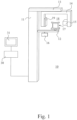
- Fig. 1 shows an X-ray imaging apparatus 10 including a vertical support structure 11 from which horizontally extend a structure 12 supporting patient support means 17 and an arm part 13 which supports a structure supporting imaging means, an arm part 14. To the arm part 14 supporting the imaging means are arranged at a distance from each other the X-ray imaging means of the apparatus, i.e.
- the apparatus includes control means, of which, Fig. 1 shows a control panel 16 positioned in connection with the arm supporting the patient support means 12.
- the apparatus 10 can be arranged via a cable into connection with a computer 30 which can be arranged with a means for processing image information produced by the apparatus and a display 31 which can display images.
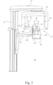
- the basic structure of the X-ray imaging apparatus shown in Fig. 2 corresponds to the basic structure of the apparatus shown in Fig. 1 .
- Fig. 2 shows a rest structure setting on the occiput.
- Fig. 3 shows a side view of such patient support structure setting on the occiput.
- a rear rest structure 170 shown in Figs. 2 and 3 comprises an actual support part 171 setting against the skull and a supporting structure 172 diverging from it.
- the supporting structure 172 consists of an elongated structure, a first end of which containing the above-mentioned support part 171 and which extends on a different side of the imaging station 18 as where the support part 171 is located.
- a second end 171' of the supporting structure 172 of the rear rest structure extends for a distance past its mounting point to the X-ray imaging apparatus 10.
- the shape of the supporting structure 172 can be some other than the one shown in Figs. 2 and 3 and can e.g. only comprise an elongated, possibly arm-like structure.
- a surface of the support part 171 of the rear rest structure pointing towards the imaging station 18 is arranged curved in the direction of the imaging station 18, substantially to correspond a curvature of a skull.
- the radius of curvature of that surface curving towards the imaging station 18 can be implemented such that it is not constant but the surface comprises an area in the middle part of the curve where the radius of curvature is smaller than the one in the edge area of the curve.
- the support part 171 adapts better than an evenly curved surface to support skulls of different sizes and also gives support to prevent the head from turning.
- the rear rest structure 170 in more detail the supporting structure 172 contained by it, is mounted to the X-ray imaging apparatus by a mounting structure 174 which can be arranged to enable adjustment of the mounting point of the rear rest structure 170 to the X-ray imaging apparatus.
- a section 172' of the rear rest structure 170 extending past its mounting point to the X-ray imaging apparatus 10 functions as a practical grabbing means when the mounting structure 174 of the rear rest structure has been arranged to enable a detachable mounting of the rear rest support 170 and when wanting to adjust the position of the support structure 171.
- Figs. 2 and 3 illustrate the implementation of the rear rest structure 170 such that the support part 171 of the rear rest structure 170 sets on a higher horizontal plane than its mounting point to the X-ray imaging apparatus 10.
- the supporting structure 172 of the rear rest structure 170 comprises an elongated arm-like structure which sets at its mounting point to the X-ray imaging apparatus 10 such that the supporting structure 172 extends towards the support part 171 at an angle of 15-25 degrees with respect to the horizontal plane.
- this angle is about 20 degrees which approximately equals the angle of a line connecting the anatomies 'tip of chin' and 'middle of occiput' with respect to the horizontal plane, when the head is in an upright position and the gaze towards the horizon.
- the measure from the ⁇ tip of chin' to the ⁇ middle of occiput' can be utilized when adjusting imaging parameter values used in X-ray imaging to correspond characteristics of the anatomy being imaged at a time.
- One way to implement this kind of an arrangement is to arrange the supporting structure 172 of the rear rest structure comprising a substantially linear part which is arranged movable but also mountable to a groove or a sleeve of substantially equal size, which then operates as the mounting structure 174 of the rear rest structure and which is arranged to the X-ray apparatus such that said substantially linear part of the supporting structure 172 of the rear rest structure is positioned at the above-mentioned angle with respect to the horizontal plane.
- the patient support means 17 of the X-ray imaging apparatus comprises a chin support structure or a bite support structure 176 and the line or the plane mentioned in the previous chapter is arranged to pass substantially via the point to which the patient's anatomy is designed to be positioned to said chin or bite support structure 176.
- the rear rest structure 170 may be arranged with a scale arranged to always be measured from the same point of the X-ray apparatus which then directly gives the position of the rear rest structure 170 within its operation area and, thus, e.g. the distance from the support part 170 of the rear rest structure to the chin or bite support of the X-ray apparatus.
- That measure may also be basis for e.g. a warning signal on that a motion path of the imaging means 15, 19 intended for use in X-ray imaging is getting so close to the patient that it is best to consider adjusting the path of movement to be different, before starting the imaging. That measure may thus indicate that the rear rest structure 170 is positioned at a place which is in the area of the part of movement of the imaging means 15, 19 during imaging, or at a distance closer than predetermined to such an area.
- Fig. 3 shows a jointed structure 173 arranged in the area between the mounting point of the rear rest structure 170 to the X-ray imaging apparatus 10 and the support part 171 of the rear rest structure which is arranged to operate as a safety mechanism 173 in the case of the patient passing out or having a panic attack during the imaging.
- a safety mechanism 173 can be arranged to go off e.g. when force greater than predetermined is acting on the support part 171 of the rear rest structure, the identification of which situation may then release the support part 171 from its patient support position.
- the above-mentioned jointed structure 173 arranged in the supporting structure 172 of the support part 171 of the rear rest structure 170 can be arranged to turn when a moment acting on it exceeds a specified limit value.
- the supporting structure 12 of the patient support means 17 is arranged with a second mounting structure 175 to which a chin support or a bite support 176 can be mounted.
- the supporting structure 172 of the support part 171 of the rear rest structure 170 is also mounted to a mounting structure 174 arranged in connection with the patient support means 17, namely in connection with a mounting structure 175 of the bite or chin support 176, but the mounting structure 174 of the rear rest structure can also be arranged elsewhere, e.g. to the supporting structure 12 of the patient support means 17 extending straight from the substantially vertical frame part 11 of the X-ray apparatus.
Landscapes
- Health & Medical Sciences (AREA)
- Life Sciences & Earth Sciences (AREA)
- Engineering & Computer Science (AREA)
- Medical Informatics (AREA)
- Heart & Thoracic Surgery (AREA)
- Animal Behavior & Ethology (AREA)
- Biophysics (AREA)
- Nuclear Medicine, Radiotherapy & Molecular Imaging (AREA)
- Optics & Photonics (AREA)
- Pathology (AREA)
- Radiology & Medical Imaging (AREA)
- Biomedical Technology (AREA)
- Physics & Mathematics (AREA)
- Molecular Biology (AREA)
- Surgery (AREA)
- High Energy & Nuclear Physics (AREA)
- General Health & Medical Sciences (AREA)
- Public Health (AREA)
- Veterinary Medicine (AREA)
- Dentistry (AREA)
- Oral & Maxillofacial Surgery (AREA)
- Neurology (AREA)
- Neurosurgery (AREA)
- Pulmonology (AREA)
- Theoretical Computer Science (AREA)
- Apparatus For Radiation Diagnosis (AREA)
- Dental Tools And Instruments Or Auxiliary Dental Instruments (AREA)
Applications Claiming Priority (2)
| Application Number | Priority Date | Filing Date | Title |
|---|---|---|---|
| FI20175241A FI127574B (fi) | 2017-03-17 | 2017-03-17 | Röntgenkuvauslaite ja potilastuki |
| PCT/FI2018/050200 WO2018167377A1 (en) | 2017-03-17 | 2018-03-19 | X-ray imaging apparatus and patient support |
Publications (4)
| Publication Number | Publication Date |
|---|---|
| EP3595531A1 EP3595531A1 (en) | 2020-01-22 |
| EP3595531A4 EP3595531A4 (en) | 2020-11-11 |
| EP3595531C0 EP3595531C0 (en) | 2024-11-20 |
| EP3595531B1 true EP3595531B1 (en) | 2024-11-20 |
Family
ID=63489978
Family Applications (1)
| Application Number | Title | Priority Date | Filing Date |
|---|---|---|---|
| EP18767424.7A Active EP3595531B1 (en) | 2017-03-17 | 2018-03-19 | X-ray imaging apparatus and patient support |
Country Status (9)
| Country | Link |
|---|---|
| US (1) | US11253222B2 (enExample) |
| EP (1) | EP3595531B1 (enExample) |
| JP (1) | JP6970209B2 (enExample) |
| KR (1) | KR102369554B1 (enExample) |
| CN (1) | CN110573082B (enExample) |
| BR (1) | BR112019019226A2 (enExample) |
| FI (1) | FI127574B (enExample) |
| RU (1) | RU2766801C2 (enExample) |
| WO (1) | WO2018167377A1 (enExample) |
Family Cites Families (26)
| Publication number | Priority date | Publication date | Assignee | Title |
|---|---|---|---|---|
| DE3627510A1 (de) * | 1986-08-13 | 1988-02-18 | Siemens Ag | Kopfpositioniereinrichtung fuer ein zahnaerztliches roentgendiagnostikgeraet |
| JP2517443Y2 (ja) * | 1989-10-05 | 1996-11-20 | 株式会社アテックス | 車輛の伝動装置 |
| US6143003A (en) | 1995-01-31 | 2000-11-07 | Cosman; Eric R. | Repositioner for head, neck, and body |
| JPH05110U (ja) * | 1991-06-19 | 1993-01-08 | 株式会社モリタ製作所 | 医科歯科用x線装置の頭部固定装置 |
| JPH0718701U (ja) * | 1993-09-14 | 1995-04-04 | 朝日レントゲン工業株式会社 | 立位ならびに仰臥位兼用全顎パノラマx線撮影装置 |
| RU2103918C1 (ru) * | 1994-05-11 | 1998-02-10 | Олег Николаевич Моргун | Способ дентальной диагностики и импульсный рентгеновский аппарат для его осуществления |
| ATE419737T1 (de) * | 2000-06-02 | 2009-01-15 | Palodex Group Oy | Bestimmung und einstellung von den belichtungswerten für röntgenstrahlung- bilderzeugung |
| JP4149189B2 (ja) * | 2002-04-04 | 2008-09-10 | 株式会社日立メディコ | X線ct装置 |
| US7350250B2 (en) * | 2005-01-10 | 2008-04-01 | Michael Froelich | Head positioning device |
| KR100707796B1 (ko) * | 2005-08-08 | 2007-04-13 | 주식회사바텍 | 파노라마 및 씨티 겸용 엑스선 촬영장치 |
| FI125008B (fi) * | 2007-03-19 | 2015-04-30 | Planmeca Oy | Panoraamaröntgenlaite ja kuvautuvan kerroksen asettaminen panoraamakuvausta varten |
| CN101416882B (zh) * | 2008-11-20 | 2010-11-10 | 王乔生 | 牙科x线三维影像系统及三维成像方法 |
| JP2010214023A (ja) * | 2009-03-18 | 2010-09-30 | Yoshida Dental Mfg Co Ltd | 歯科用x線撮影装置における頭部固定装置 |
| US10820866B2 (en) * | 2009-05-12 | 2020-11-03 | Michael Campagna | Articulating patient positioning apparatus |
| EP2387945B1 (de) * | 2010-05-18 | 2015-12-02 | White Lion Technologies AG | Verfahren und Vorrichtung zur digitalen Volumentomographie |
| ITBO20110764A1 (it) * | 2011-12-28 | 2013-06-29 | Cefla Coop | Dispositivo per l'acquisizione di radiografie panoramiche, teleradiografie e opzionalmente radiografie volumetriche cbct |
| US10732244B2 (en) * | 2012-03-26 | 2020-08-04 | Sirona Dental Systems Gmbh | Systems, methods, apparatuses, and computer-readable storage media for performing diagnostic examinations using MRI |
| GB201215877D0 (en) * | 2012-09-05 | 2012-10-24 | Renishaw Plc | Medical imaging accessory |
| FI124596B (fi) * | 2012-11-23 | 2014-10-31 | Planmed Oy | Lääketieteellinen tietokonetomografiakuvauslaitteisto |
| KR101510859B1 (ko) * | 2013-07-30 | 2015-04-17 | 경희대학교 산학협력단 | 방사선 영상 촬영용 두부 고정장치 |
| KR101838349B1 (ko) * | 2014-04-17 | 2018-03-13 | 쎄플라 쏘씨에타 쿠퍼라티바 | 구강외 치과 방사선영상을 획득하기 위한 두개 고정기 |
| US9301726B2 (en) * | 2014-05-02 | 2016-04-05 | Wisconsin Alumni Research Foundation | CT machine for multi-angle scanning of stationary patients |
| JP5881192B2 (ja) * | 2014-06-24 | 2016-03-09 | 学校法人日本大学 | パノラマx線撮影装置及びパノラマx線撮影方法 |
| EP3200714B1 (en) * | 2014-09-30 | 2025-01-29 | Orfit Industries | Profile for the attachment of an immobilisation mask |
| KR101659177B1 (ko) * | 2014-12-15 | 2016-09-23 | 오스템임플란트 주식회사 | 치과용 두부 정렬장치 |
| CN205458749U (zh) * | 2016-03-07 | 2016-08-17 | 中国人民解放军第四军医大学 | 一种脑灌注ct扫描用推撑装置 |
-
2017
- 2017-03-17 FI FI20175241A patent/FI127574B/fi active IP Right Grant
-
2018
- 2018-03-19 CN CN201880028717.3A patent/CN110573082B/zh active Active
- 2018-03-19 US US16/494,480 patent/US11253222B2/en active Active
- 2018-03-19 EP EP18767424.7A patent/EP3595531B1/en active Active
- 2018-03-19 KR KR1020197030035A patent/KR102369554B1/ko active Active
- 2018-03-19 BR BR112019019226A patent/BR112019019226A2/pt not_active Application Discontinuation
- 2018-03-19 RU RU2019131049A patent/RU2766801C2/ru active
- 2018-03-19 JP JP2019551390A patent/JP6970209B2/ja active Active
- 2018-03-19 WO PCT/FI2018/050200 patent/WO2018167377A1/en not_active Ceased
Also Published As
| Publication number | Publication date |
|---|---|
| EP3595531C0 (en) | 2024-11-20 |
| US20200085403A1 (en) | 2020-03-19 |
| CN110573082A (zh) | 2019-12-13 |
| JP2020511241A (ja) | 2020-04-16 |
| KR102369554B1 (ko) | 2022-03-03 |
| BR112019019226A2 (pt) | 2020-04-14 |
| CN110573082B (zh) | 2024-01-09 |
| EP3595531A4 (en) | 2020-11-11 |
| US11253222B2 (en) | 2022-02-22 |
| EP3595531A1 (en) | 2020-01-22 |
| RU2766801C2 (ru) | 2022-03-15 |
| RU2019131049A3 (enExample) | 2021-05-19 |
| JP6970209B2 (ja) | 2021-11-24 |
| FI127574B (fi) | 2018-09-14 |
| WO2018167377A1 (en) | 2018-09-20 |
| FI20175241A1 (fi) | 2018-09-14 |
| RU2019131049A (ru) | 2021-04-19 |
| KR20190125466A (ko) | 2019-11-06 |
Similar Documents
| Publication | Publication Date | Title |
|---|---|---|
| JP5828957B2 (ja) | 口腔外撮像における患者位置決め用シールド | |
| US20120321051A1 (en) | Patient support for an odontological x-ray apparatus | |
| US10441227B2 (en) | Cephalostat | |
| US11096637B2 (en) | X-ray imaging apparatus and patient support safety mechanism | |
| EP3595531B1 (en) | X-ray imaging apparatus and patient support | |
| EP3595530B1 (en) | X-ray imaging apparatus and patient support arrangement | |
| CN107613875B (zh) | 用于放射线拍摄的防护装备 | |
| HK40018966A (en) | X-ray imaging apparatus and patient support | |
| HK40019000A (en) | X-ray imaging apparatus and patient support arrangement | |
| HK40018966B (zh) | X射线成像设备和患者支撑件 | |
| HK40019000B (zh) | X射线成像设备和患者支撑装置 | |
| BR112019019233B1 (pt) | Aparelho de imageamento por raio x |
Legal Events
| Date | Code | Title | Description |
|---|---|---|---|
| STAA | Information on the status of an ep patent application or granted ep patent |
Free format text: STATUS: THE INTERNATIONAL PUBLICATION HAS BEEN MADE |
|
| PUAI | Public reference made under article 153(3) epc to a published international application that has entered the european phase |
Free format text: ORIGINAL CODE: 0009012 |
|
| STAA | Information on the status of an ep patent application or granted ep patent |
Free format text: STATUS: REQUEST FOR EXAMINATION WAS MADE |
|
| 17P | Request for examination filed |
Effective date: 20191004 |
|
| AK | Designated contracting states |
Kind code of ref document: A1 Designated state(s): AL AT BE BG CH CY CZ DE DK EE ES FI FR GB GR HR HU IE IS IT LI LT LU LV MC MK MT NL NO PL PT RO RS SE SI SK SM TR |
|
| AX | Request for extension of the european patent |
Extension state: BA ME |
|
| DAV | Request for validation of the european patent (deleted) | ||
| DAX | Request for extension of the european patent (deleted) | ||
| A4 | Supplementary search report drawn up and despatched |
Effective date: 20201012 |
|
| RIC1 | Information provided on ipc code assigned before grant |
Ipc: A61B 6/04 20060101AFI20201006BHEP Ipc: A61B 6/14 20060101ALI20201006BHEP Ipc: A61B 6/10 20060101ALI20201006BHEP Ipc: A61B 6/00 20060101ALI20201006BHEP |
|
| STAA | Information on the status of an ep patent application or granted ep patent |
Free format text: STATUS: EXAMINATION IS IN PROGRESS |
|
| 17Q | First examination report despatched |
Effective date: 20220622 |
|
| GRAP | Despatch of communication of intention to grant a patent |
Free format text: ORIGINAL CODE: EPIDOSNIGR1 |
|
| STAA | Information on the status of an ep patent application or granted ep patent |
Free format text: STATUS: GRANT OF PATENT IS INTENDED |
|
| RIC1 | Information provided on ipc code assigned before grant |
Ipc: A61B 6/00 20060101ALI20240606BHEP Ipc: A61B 6/51 20240101ALI20240606BHEP Ipc: A61B 6/50 20240101ALI20240606BHEP Ipc: A61B 6/40 20240101ALI20240606BHEP Ipc: A61B 6/03 20060101ALI20240606BHEP Ipc: A61B 6/04 20060101AFI20240606BHEP |
|
| INTG | Intention to grant announced |
Effective date: 20240621 |
|
| GRAS | Grant fee paid |
Free format text: ORIGINAL CODE: EPIDOSNIGR3 |
|
| GRAA | (expected) grant |
Free format text: ORIGINAL CODE: 0009210 |
|
| STAA | Information on the status of an ep patent application or granted ep patent |
Free format text: STATUS: THE PATENT HAS BEEN GRANTED |
|
| AK | Designated contracting states |
Kind code of ref document: B1 Designated state(s): AL AT BE BG CH CY CZ DE DK EE ES FI FR GB GR HR HU IE IS IT LI LT LU LV MC MK MT NL NO PL PT RO RS SE SI SK SM TR |
|
| REG | Reference to a national code |
Ref country code: GB Ref legal event code: FG4D |
|
| REG | Reference to a national code |
Ref country code: CH Ref legal event code: EP |
|
| REG | Reference to a national code |
Ref country code: DE Ref legal event code: R096 Ref document number: 602018076739 Country of ref document: DE |
|
| REG | Reference to a national code |
Ref country code: IE Ref legal event code: FG4D |
|
| U01 | Request for unitary effect filed |
Effective date: 20241210 |
|
| U07 | Unitary effect registered |
Designated state(s): AT BE BG DE DK EE FI FR IT LT LU LV MT NL PT RO SE SI Effective date: 20241219 |
|
| U20 | Renewal fee for the european patent with unitary effect paid |
Year of fee payment: 8 Effective date: 20250210 |
|
| PG25 | Lapsed in a contracting state [announced via postgrant information from national office to epo] |
Ref country code: IS Free format text: LAPSE BECAUSE OF FAILURE TO SUBMIT A TRANSLATION OF THE DESCRIPTION OR TO PAY THE FEE WITHIN THE PRESCRIBED TIME-LIMIT Effective date: 20250320 Ref country code: HR Free format text: LAPSE BECAUSE OF FAILURE TO SUBMIT A TRANSLATION OF THE DESCRIPTION OR TO PAY THE FEE WITHIN THE PRESCRIBED TIME-LIMIT Effective date: 20241120 |
|
| PG25 | Lapsed in a contracting state [announced via postgrant information from national office to epo] |
Ref country code: ES Free format text: LAPSE BECAUSE OF FAILURE TO SUBMIT A TRANSLATION OF THE DESCRIPTION OR TO PAY THE FEE WITHIN THE PRESCRIBED TIME-LIMIT Effective date: 20241120 |
|
| PG25 | Lapsed in a contracting state [announced via postgrant information from national office to epo] |
Ref country code: NO Free format text: LAPSE BECAUSE OF FAILURE TO SUBMIT A TRANSLATION OF THE DESCRIPTION OR TO PAY THE FEE WITHIN THE PRESCRIBED TIME-LIMIT Effective date: 20250220 |
|
| PG25 | Lapsed in a contracting state [announced via postgrant information from national office to epo] |
Ref country code: GR Free format text: LAPSE BECAUSE OF FAILURE TO SUBMIT A TRANSLATION OF THE DESCRIPTION OR TO PAY THE FEE WITHIN THE PRESCRIBED TIME-LIMIT Effective date: 20250221 |
|
| PG25 | Lapsed in a contracting state [announced via postgrant information from national office to epo] |
Ref country code: PL Free format text: LAPSE BECAUSE OF FAILURE TO SUBMIT A TRANSLATION OF THE DESCRIPTION OR TO PAY THE FEE WITHIN THE PRESCRIBED TIME-LIMIT Effective date: 20241120 |
|
| PG25 | Lapsed in a contracting state [announced via postgrant information from national office to epo] |
Ref country code: RS Free format text: LAPSE BECAUSE OF FAILURE TO SUBMIT A TRANSLATION OF THE DESCRIPTION OR TO PAY THE FEE WITHIN THE PRESCRIBED TIME-LIMIT Effective date: 20250220 |
|
| PG25 | Lapsed in a contracting state [announced via postgrant information from national office to epo] |
Ref country code: SM Free format text: LAPSE BECAUSE OF FAILURE TO SUBMIT A TRANSLATION OF THE DESCRIPTION OR TO PAY THE FEE WITHIN THE PRESCRIBED TIME-LIMIT Effective date: 20241120 |
|
| PG25 | Lapsed in a contracting state [announced via postgrant information from national office to epo] |
Ref country code: SK Free format text: LAPSE BECAUSE OF FAILURE TO SUBMIT A TRANSLATION OF THE DESCRIPTION OR TO PAY THE FEE WITHIN THE PRESCRIBED TIME-LIMIT Effective date: 20241120 |
|
| PG25 | Lapsed in a contracting state [announced via postgrant information from national office to epo] |
Ref country code: CZ Free format text: LAPSE BECAUSE OF FAILURE TO SUBMIT A TRANSLATION OF THE DESCRIPTION OR TO PAY THE FEE WITHIN THE PRESCRIBED TIME-LIMIT Effective date: 20241120 |
|
| PLBE | No opposition filed within time limit |
Free format text: ORIGINAL CODE: 0009261 |
|
| STAA | Information on the status of an ep patent application or granted ep patent |
Free format text: STATUS: NO OPPOSITION FILED WITHIN TIME LIMIT |
|
| PG25 | Lapsed in a contracting state [announced via postgrant information from national office to epo] |
Ref country code: MC Free format text: LAPSE BECAUSE OF FAILURE TO SUBMIT A TRANSLATION OF THE DESCRIPTION OR TO PAY THE FEE WITHIN THE PRESCRIBED TIME-LIMIT Effective date: 20241120 |
|
| 26N | No opposition filed |
Effective date: 20250821 |
|
| REG | Reference to a national code |
Ref country code: CH Ref legal event code: H13 Free format text: ST27 STATUS EVENT CODE: U-0-0-H10-H13 (AS PROVIDED BY THE NATIONAL OFFICE) Effective date: 20251023 |
|
| GBPC | Gb: european patent ceased through non-payment of renewal fee |
Effective date: 20250319 |