EP3594618B1 - Vorrichtung zur messung dreidimensionaler formen, verfahren zur messung dreidimensionaler formen und programm - Google Patents
Vorrichtung zur messung dreidimensionaler formen, verfahren zur messung dreidimensionaler formen und programm Download PDFInfo
- Publication number
- EP3594618B1 EP3594618B1 EP17900273.8A EP17900273A EP3594618B1 EP 3594618 B1 EP3594618 B1 EP 3594618B1 EP 17900273 A EP17900273 A EP 17900273A EP 3594618 B1 EP3594618 B1 EP 3594618B1
- Authority
- EP
- European Patent Office
- Prior art keywords
- light
- phase
- observation
- reflection light
- dimensional shape
- Prior art date
- Legal status (The legal status is an assumption and is not a legal conclusion. Google has not performed a legal analysis and makes no representation as to the accuracy of the status listed.)
- Active
Links
Images


Classifications
-
- G—PHYSICS
- G06—COMPUTING OR CALCULATING; COUNTING
- G06T—IMAGE DATA PROCESSING OR GENERATION, IN GENERAL
- G06T7/00—Image analysis
- G06T7/50—Depth or shape recovery
- G06T7/514—Depth or shape recovery from specularities
-
- G—PHYSICS
- G01—MEASURING; TESTING
- G01B—MEASURING LENGTH, THICKNESS OR SIMILAR LINEAR DIMENSIONS; MEASURING ANGLES; MEASURING AREAS; MEASURING IRREGULARITIES OF SURFACES OR CONTOURS
- G01B11/00—Measuring arrangements characterised by the use of optical techniques
- G01B11/24—Measuring arrangements characterised by the use of optical techniques for measuring contours or curvatures
- G01B11/25—Measuring arrangements characterised by the use of optical techniques for measuring contours or curvatures by projecting a pattern, e.g. one or more lines, moiré fringes on the object
-
- G—PHYSICS
- G06—COMPUTING OR CALCULATING; COUNTING
- G06T—IMAGE DATA PROCESSING OR GENERATION, IN GENERAL
- G06T7/00—Image analysis
- G06T7/50—Depth or shape recovery
- G06T7/521—Depth or shape recovery from laser ranging, e.g. using interferometry; from the projection of structured light
-
- G—PHYSICS
- G01—MEASURING; TESTING
- G01B—MEASURING LENGTH, THICKNESS OR SIMILAR LINEAR DIMENSIONS; MEASURING ANGLES; MEASURING AREAS; MEASURING IRREGULARITIES OF SURFACES OR CONTOURS
- G01B11/00—Measuring arrangements characterised by the use of optical techniques
- G01B11/24—Measuring arrangements characterised by the use of optical techniques for measuring contours or curvatures
- G01B11/25—Measuring arrangements characterised by the use of optical techniques for measuring contours or curvatures by projecting a pattern, e.g. one or more lines, moiré fringes on the object
- G01B11/2518—Projection by scanning of the object
- G01B11/2527—Projection by scanning of the object with phase change by in-plane movement of the patern
-
- G—PHYSICS
- G01—MEASURING; TESTING
- G01B—MEASURING LENGTH, THICKNESS OR SIMILAR LINEAR DIMENSIONS; MEASURING ANGLES; MEASURING AREAS; MEASURING IRREGULARITIES OF SURFACES OR CONTOURS
- G01B11/00—Measuring arrangements characterised by the use of optical techniques
- G01B11/24—Measuring arrangements characterised by the use of optical techniques for measuring contours or curvatures
- G01B11/25—Measuring arrangements characterised by the use of optical techniques for measuring contours or curvatures by projecting a pattern, e.g. one or more lines, moiré fringes on the object
- G01B11/2536—Measuring arrangements characterised by the use of optical techniques for measuring contours or curvatures by projecting a pattern, e.g. one or more lines, moiré fringes on the object using several gratings with variable grating pitch, projected on the object with the same angle of incidence
-
- G—PHYSICS
- G01—MEASURING; TESTING
- G01B—MEASURING LENGTH, THICKNESS OR SIMILAR LINEAR DIMENSIONS; MEASURING ANGLES; MEASURING AREAS; MEASURING IRREGULARITIES OF SURFACES OR CONTOURS
- G01B9/00—Measuring instruments characterised by the use of optical techniques
- G01B9/02—Interferometers
- G01B9/02001—Interferometers characterised by controlling or generating intrinsic radiation properties
- G01B9/0201—Interferometers characterised by controlling or generating intrinsic radiation properties using temporal phase variation
-
- G—PHYSICS
- G01—MEASURING; TESTING
- G01C—MEASURING DISTANCES, LEVELS OR BEARINGS; SURVEYING; NAVIGATION; GYROSCOPIC INSTRUMENTS; PHOTOGRAMMETRY OR VIDEOGRAMMETRY
- G01C11/00—Photogrammetry or videogrammetry, e.g. stereogrammetry; Photographic surveying
- G01C11/02—Picture taking arrangements specially adapted for photogrammetry or photographic surveying, e.g. controlling overlapping of pictures
- G01C11/025—Picture taking arrangements specially adapted for photogrammetry or photographic surveying, e.g. controlling overlapping of pictures by scanning the object
-
- G—PHYSICS
- G06—COMPUTING OR CALCULATING; COUNTING
- G06T—IMAGE DATA PROCESSING OR GENERATION, IN GENERAL
- G06T7/00—Image analysis
- G06T7/50—Depth or shape recovery
- G06T7/55—Depth or shape recovery from multiple images
-
- G—PHYSICS
- G06—COMPUTING OR CALCULATING; COUNTING
- G06T—IMAGE DATA PROCESSING OR GENERATION, IN GENERAL
- G06T2207/00—Indexing scheme for image analysis or image enhancement
- G06T2207/20—Special algorithmic details
- G06T2207/20048—Transform domain processing
- G06T2207/20056—Discrete and fast Fourier transform, [DFT, FFT]
-
- G—PHYSICS
- G06—COMPUTING OR CALCULATING; COUNTING
- G06T—IMAGE DATA PROCESSING OR GENERATION, IN GENERAL
- G06T2207/00—Indexing scheme for image analysis or image enhancement
- G06T2207/20—Special algorithmic details
- G06T2207/20092—Interactive image processing based on input by user
- G06T2207/20104—Interactive definition of region of interest [ROI]
Definitions
- the present invention relates to a technique to project a cyclic pattern to a measurement object, and to measure a three-dimensional shape of the measurement object using an observed image.
- a phase shifting method is known as a technique to measure a three-dimensional shape of an object using an image.
- the phase shift method is a method of projecting a cyclic pattern to a measurement object using a projector, and analyzing the distortion (phase shift) of the projection pattern that is generated depending on the irregularities on the object surface, so as to restore the three-dimensional shape of the object surface.
- MPS micro phase shifting
- Fig. 6 depicts a measurement system using an imaging device 200 and a projector 201.
- Light 201L having a predetermined pattern is projected from the projector 201 to a measurement object 202, and the projection pattern acquired on the surface of the measurement object 202 is captured by the imaging device 200.
- the distortion of the projection pattern generated by the surface irregularities of the measurement object 202 appears as a brightness change of the image.
- the positional relationship among the projector 201, a point on the surface of the measurement object 202 and the imaging device 200 is specified, whereby the height (three-dimensional position) of the surface of the measurement object 202 can be calculated using the triangulation.
- the observation light observed by the imaging device 200 contains not only reflected light 201R (primary reflection light) of the light 201L of the projector 201, but also reflected light 203R (secondary reflection light or multiple reflection light) of the light 203L from the object 203.
- This secondary reflection light 203R becomes noise, and is superimposed on the projection pattern on the surface of the measurement object 202, hence an analysis of this projection pattern (that is, calculation of the phase value of the observation light) is affected thereby, and a measurement error is generated.
- This phenomenon is called “secondary reflection” or “multiple reflection”.
- PTL 1 proposes a method of specifying a portion which causes the multiple reflection and imaging a projection pattern projected on this portion in a dimmed or extinguished light state.
- a portion where the three-dimensional shape cannot be measured that is, a blind spot
- this method cannot effectively suppress multiple reflection unless the portion which causes the multiple reflection (portion of the projection pattern for which light is dimmed or extinguished) is accurately specified in advance, hence implementing this method in an actual apparatus is difficult.
- a hybrid 3D reconstruction framework is represented that supplements projected pattern correspondence matching with texture information.
- the proposed scheme consists of using projected pattern data to derive initial correspondences across cameras and then using texture data to eliminate ambiguities. Pattern modulation data are then used to estimate error models from which Kullback-Leibler divergence refinement is applied to reduce misregistration errors.
- phase measuring profilometry which is a method for measuring the 3D profile of objects.
- this article discloses a modelling of the smoothing as a mathematical smooth mask applying process. Accordingly, a novel de-convolution method specified for recovering the phase in the high-contrast regions is disclosed.
- the multiple paths can be represented as the summation of a direct return, which is the return from the shortest path length, and a global return, which includes all other returns.
- a direct return which is the return from the shortest path length
- a global return which includes all other returns.
- NPL 1 Gupta, Mohit, and Shree K. Nayar. "Micro phase shifting.” Computer Vision and Pattern Recognition (CVPR), 2012 IEEE Conference on. IEEE, 2012 .
- the present invention uses a configuration to estimate a phase error caused by multiple reflection based on samples of the brightness amplitude values of the measurement light at a plurality of points, and correct the phase value of the observation light using this phase error.
- a three-dimensional shape measurement device includes: a projection device which projects a pattern having cyclicity in a time direction and a space direction to a measurement object; an imaging device which captures an image of the measurement object; and a control device which measures a three-dimensional shape of the measurement object using a plurality of observation images captured by the imaging device while changing a phase of a pattern projected from the projection device.
- observation light observed by the imaging device is composite light of primary reflection light and secondary reflection light, the primary reflection light being light which is projected from the projection device, is reflected at a measurement point on the measurement object and enters the imaging device, the secondary reflection light being light which is projected from the projection device, is reflected on another reflection surface, is reflected at the measurement point on the measurement object and enters the imaging device; acquires three or more samples of a brightness amplitude value of the observation light based on the plurality of observation images; calculates a phase error, ⁇ , caused by the secondary reflection light by solving the following expression (ii) for the three unknown quantities, a, b, and a, using three or more acquired samples, of which the conditions of the brightness amplitude value, c, of the observation light are mutually different, and by inserting the values, a, b, and a, determined from expression (ii) into expression (i); calculates a phase value of the observation light based on the plurality of observation images; calculates a corrected phase value by
- a three-dimensional shape is calculated based on the phase value after correcting the phase error caused by the secondary reflection light, hence high precision three-dimensional shape measurement, with less influence of multiple reflection, can be implemented.
- the method of the present invention does not interrupt the measurement of the three-dimensional shape, unlike conventional methods, and can be applied regardless whether multiple reflection is actually generated in the portion or not, therefore this method can be easily implemented in an actual apparatus.
- three or more samples are samples conditions of which are different in at least one of: the position of the pixel on the observation image; and the spatial frequency of the pattern.
- the three or more samples are the brightness amplitude values that are observed for three or more pixels on the observation image using one type of frequency pattern, and the three or more pixels are pixels such that phases of the pattern at positions of the pixels are different from each other. This is because only one type of pattern is required, which means that a number of times of capturing the observation image can be less.
- the three or more pixels are selected for a local region on the observation image. This is because pixels in a local region (micro region that can be approximated as a plane) can be regarded as pixels under the same conditions (i.e., reflectance of the measurement object surface).
- the three or more pixels are pixels which line up in a direction parallel with an epi-polar line on the observation image. This is because selecting samples like this makes it possible to accurately calculate the phase error using a minimum number of samples.
- the three or more samples are brightness amplitude values observed for one pixel on the observation image using three or more types of frequency patterns.
- the samples for the sample pixel are used, hence phase error can be estimated more accurately.
- control device stores reference information that defines a relationship of a first index on the brightness amplitude value, a second index on the spatial frequency of the pattern to be projected, and a third index on the phase difference between the primary reflection light and the secondary reflection light, and determines the phase difference between the primary reflection light and the secondary reflection light based on the three or more samples, the spatial frequency of the pattern projected when each sample was observed, and the reference information.
- the value of the phase difference between the primary reflection light and the secondary reflection light can be calculated simply and accurately from the values of the three or more samples.
- control device calculates the three-dimensional position of the measurement point on the measurement object by the phase shift method or micro phase shifting (MPS) based on the corrected phase value. It is preferable that the another reflection surface is a specular reflection surface.
- the present invention may be regarded as a three-dimensional shape measurement device or an image processing device that includes at least a part of the above mentioned configurations or functions.
- the present invention may also be regarded as an inspection apparatus, a three-dimensional scanner or an object recognition apparatus that includes this three-dimensional shape measurement device.
- the present invention may be regarded as a three-dimensional shape measurement method, an image processing method, an inspection method, or an object recognition method that includes at least a part of the above mentioned processing, or a program that causes a computer to execute these methods, or a non-transitory computer readable recording medium that records this program.
- Each of the above mentioned configurations and processing may be combined with each other to constitute the present invention, as long as no technical inconsistency is generated.
- the influence of multiple reflection can be reduced and the measurement accuracy can be improved in a method of measuring a three-dimensional shape based on a phase of a pattern projected to the measurement object.
- the present invention relates to a three-dimensional shape measurement technique to measure a three-dimensional shape of a measurement object based on the change of the phase of a pattern projected to the measurement object, and more particularly to a method of reducing the influence of multiple reflection caused by a reflection surface that exists around the measurement object, and improving the measurement accuracy.
- the present invention can be suitably applied to a three-dimensional shape measurement using a phase shift method or micro phase shifting (MPS), which is an improved phase shift method.
- MPS micro phase shifting
- the three-dimensional shape measurement according to the present invention can be applied to various apparatuses, such as a three-dimensional scanner which measures the surface shape of an object, an inspection apparatus which inspects an object based on a measured three-dimensional shape, and an apparatus which performs object recognition or individual identification based on a measured three-dimensional shape.
- a three-dimensional scanner which measures the surface shape of an object
- an inspection apparatus which inspects an object based on a measured three-dimensional shape
- an apparatus which performs object recognition or individual identification based on a measured three-dimensional shape For example, in the case of a visual inspection apparatus for a surface mount substrate, multiple reflection caused by the metal components on the substrate may drop inspection accuracy, therefore the three-dimensional shape measurement according to the present invention can be especially useful if applied.
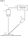
- Fig. 1 is a schematic diagram depicting a hardware configuration of the three-dimensional shape measurement device.
- the three-dimensional shape measurement device 1 is an apparatus to measure a three-dimensional shape of a measurement object O, and is constituted of a projection device (projector) 10, an imaging device (camera) 11, and a control device (computer) 12.
- the projection device 10 is a projection unit that projects a pattern which has a cyclicity in the time direction and the space direction to the measurement object O.
- a number of projection devices 10 may be one, but a plurality of projection devices 10 may be disposed so that the pattern can be projected to the projection device 10 in a plurality of directions.
- a digital light processing (DLP) projector using a digital mirror device, can be preferably used. This is because a DLP projector can easily change the projection patterns.
- the imaging device 11 is a unit that captures an image of a measurement object O to which a pattern is projected, and outputs a digital image.
- the imaging device 11 is constituted of an optical system and an image sensor, for example. When the three-dimensional shape measurement is performed, the imaging device 11 captures a plurality of images while changing the phase of the pattern projected from the projection device 10 (also while changing the frequency of the pattern in the case of performing the phase unwrapping). An image of the measurement object O that is captured by the imaging device 11 is called an "observation image".
- the control device 12 is a unit that has such functions as: controlling the projection device 10 and the imaging device 11; processing an image captured by the imaging device 11; and measuring a three-dimensional shape.
- the control device 12 may be a computer which includes a CPU (processor), a memory, a non-volatile storage device (e.g. hard disk, flash memory), an input device (e.g. keyboard, mouse, touch panel), and a display device (e.g. liquid crystal display).
- Each function of the control device 12, which will be described later, can be implemented by loading a program stored in the non-volatile storage device, and the CPU executing this program. However all or a part of the functions of the control device 12 may be performed by an ASIC, an FPGA or dedicated hardware. Further, the functions of the control device 12 may be implemented by the collaboration of a plurality of computers using techniques of distributed computing and dedicated hardware.
- Fig. 2 is a block diagram depicting the functions of the control device 12 related to the three-dimensional shape measurement.
- the control device 12 includes an image acquisition unit 20, a region setting unit 21, a phase calculation unit 22, and a three-dimensional restoration unit 23.
- the image acquisition unit 20 has a function to acquire a plurality of observation images used for the three-dimensional shape measurement from the imaging device 11.
- the region setting unit 21 has a function to set a region on which the later mentioned multiple reflection correction is performed (hereafter called "correction region"), out of a visual field of the observation image.
- the phase calculation unit 22 has a function to calculate the phase value of a pattern in each pixel on the observation image (that is, each measurement point on the surface of the measurement object O) by analyzing the observation image.
- the three-dimensional restoration unit 23 has a function to calculate a three-dimensional position of each pixel (that is, each measurement point on the surface of the measurement object O) on the observation image based on the phase values calculated by the phase calculation unit 22.
- Fig. 3 illustrates a model of multiple reflection and observation light.
- a system in which a reflection surface R having high specularity (e.g. surface of a metal object) exists near a measurement object O will be considered.
- a sinusoidal fringe pattern is projected from the projection device 10
- light L1 direct light
- reflection light L20 of light L2 which is emitted from a point x2 on the panel 100 of the projection device 10 and is reflected on a reflection surface R
- the point x on the panel 100 of the projection device 10 is regarded as a point light source, and is called a "projection light source x".
- I O c sin ⁇ M
- I 1 a 1 R 1 sin w f t + k f x 1 + ⁇
- I 2 a 1 R 1 R 2 sin w f t + k f x 1 + ⁇ + k f x 2 ⁇ x 1
- c is a brightness amplitude value of the observation light Io
- ⁇ M is a phase value of the observation light I O
- a 1 is a maximum brightness of the fringe pattern
- R 1 is a reflectance of the measurement point P
- R 2 is a reflectance of the reflection surface R
- w f is an angular velocity of the fringe pattern
- t is time.
- k f if a wave number of the fringe pattern
- x 1 is a position of the projection light source of the light L1
- x 2 is a position of the projection light source of the light L2.
- ⁇ is an initial phase of the fringe pattern.
- R 1 , R 2 , x 1 and x 2 are unknown.
- Expression (8) can be solved if at least three samples, of which conditions of the brightness amplitude value c of the observation light I O are mutually different, are actually measured. Then the values a, b, and a, determined from Expression (8), are inserted into Expression (7), then the phase error ⁇ caused by the secondary reflection light I 2 can be derived, and the true value ⁇ true of the phase can be determined from the observed phase value ⁇ M and Expression (6).
- the operation of calculating the true value ⁇ true of the phase (phase value in the case of not being influenced by the secondary reflection light I 2 ) using the above mentioned model is called "multiple reflection correction".
- the control device 12 controls the projection device 10 and the imaging device 11, and captures a plurality of observation images.
- the control device 12 projects a fringe pattern of which brightness changes sinusoidally (maximum brightness: a 1 , wave number: k f ), four times while changing the phase by ⁇ /4 at a time, and captures four observation images.
- capturing the observation image may be repeated with changing the wave number (frequency) of the fringe pattern.
- a fringe pattern at high frequency for measurement and a fringe pattern at low frequency for unwrapping are captured, or in the case of MPS, a plurality of types of fringe patters at high frequency are captured.
- the data of the observation image is loaded into the control device 12 by the image acquiring unit 20, and is stored in the memory or the non-volatile storage device.
- the region setting unit 21 sets a correction region out of the visual field of the observation image.
- the correction image may be set by any method. For example, an image acquired from the imaging device 11 may be displayed on the display device, and the user may specify the region using an input device. Or the region setting unit 21 may analyze the observation image, detect (estimate) a region where multiple reflection is generated, and automatically set the correction region. If the measurement object is an industrial product, such as a surface mount substrate, the region setting unit 21 may detect the existence of a reflection surface R, and a region where multiple reflection may be generated, based on the design data (CAD data) or the like, and automatically set the correction region.
- CAD data design data
- a region where the multiple reflection correction is performed is limited like this, whereby the processing load required for the multiple reflection correction can be reduced, and the processing time of the three-dimensional shape measurement can be decreased. If it is not necessary to decrease the processing time, the multiple reflection correction may be performed for the entire region of the observation image. In this case, the processing in step S41 can be omitted.
- step S42 the phase calculation unit 22 performs a fast Fourier transform (FFT) for a plurality of observation images which were captured with changing the phase, and calculates the brightness amplitude value c and the phase value ⁇ M of the observation light at each pixel on the observation image.
- FFT fast Fourier transform
- step S43 the phase calculation unit 22 selects a pixel to be a processing target (hereafter called "target pixel p 0 "), out of the correction region that was set in step S41. Then in step S44, the phase calculation unit 22 acquires three or more samples of the brightness amplitude value c of the measurement light for the target pixel p 0 .
- the three or more samples of the brightness amplitude value c of the measurement light can be selected so as to be mutually different in at least one of the conditions of "position of the pixel on the observation image” and "spatial frequency of the fringe pattern".
- the brightness amplitude values c 00 , c 01 , c 02 ... observed in one type of fringe pattern having a wave number k f0 may be selected as the three or more samples for each of the target pixel p 0 and the neighboring pixels p 1 , p 2 ... thereof.
- this method only one type of wave number of the fringe pattern is required, hence a number of times of capturing the observation image can be lessened.
- the pixels p 0 , p 1 , p 2 ... in the local region can be regarded as pixels under the same conditions, such as reflectance of the measurement object surface.
- the pixels p 0 , p 1 , p 2 ... are selected from positions in which a phase of the fringe pattern is mutually different.
- the pixels are pixels which line up in a direction parallel with an epi-polar line. This is because selecting samples like this make it possible to accurately calculate the phase error using a minimum number of samples.
- the brightness amplitude values c 00 , c 10 , c 20 ... observed in three or more types of fringe patterns having the wave numbers k f0 , k f1 , k f2 ... may be selected as the three or more samples for the target pixel p 0.
- samples of the same pixel (same measurement point) are used, hence phase error estimation becomes more accurate.
- This method is preferable especially when the shape (irregularity) of the surface of the measurement object and reflectance thereof are not uniform.
- the wave numbers k f0 , k f1 , k f2 ... are selected so that one wave number does not becomes an integral multiple of another wave number.
- the brightness amplitude values of the target pixel p 0 which was observed using three or more types of fringe patterns at high frequency, can be directly used as the three or more samples.
- the brightness amplitude values c 00 , c 01 , c 11 ... or the brightness amplitude values c 00 , c 11 , c 22 ..., of which conditions are different in both the positions of the pixel and the wave number of the fringe pattern, may be used as the three or more samples. In other words, samples of which conditions are different in both the positions of the pixel and the spatial frequency of the fringe pattern may be used.
- step S45 the phase calculation unit 22 calculates the phase error ⁇ caused by the secondary reflection light by solving Expression (7) and Expression (8) using the three or more samples of the brightness amplitude values acquired in step S44. Then in step S46, the phase calculation unit 22 calculates the corrected phase value ⁇ true of the target pixel p 0 by correcting the phase value ⁇ M using the phase error ⁇ .
- steps S43 to S46 are performed for all the pixels in the correction region (step S47).
- step S48 the three-dimensional restoration unit 23 calculates a three-dimensional position of each pixel on the observation image (that is, each measurement point on the measurement object), based on the phase value of each pixel (corrected phase value if the pixel is in the correction region) calculated by the phase calculation unit 22. Thereby the three-dimensional shape of the measurement object surface can be restored.
- the phase shift method, MPS or the like can be used. These algorithms are publicly known, hence detailed description is omitted here.
- the three-dimensional shape is calculated based on the phase value after correcting the phase error caused by the secondary reflection light, hence accurate three-dimensional shape measurement, in which the influence of multiple reflection is reduced, can be implemented.
- the multiple reflection correction of this embodiment does not interrupt the measurement of the three-dimensional shape, unlike the conventional methods, and can be applied regardless whether the multiple reflection is actually generated in the portion or not, therefore this method can be easily implemented in an actual apparatus is easy.
- phase error calculation method by the phase calculation unit 22, that is, a specific method of solving Expression (7) and Expression (8), will be described next.
- c 2 is selected as the first index on the brightness amplitude value
- "1/k f " is selected as the second index on the spatial frequency of the fringe pattern to be projected
- "x 2 - x 1 " is selected as the third index on the phase difference between the primary reflection light and the secondary reflection light.
- the combination of the first to third index values that satisfies Expression (9) is calculated by setting appropriate constants for a and b, whereby reflectance information (three-dimensional table) that defines the relationship of the first to third indices is created and stored in the storage device of the control device 12 in advance.
- Fig. 5 is a conceptual diagram depicting the relationship of the first to third index values in the reference information.
- the abscissa indicates a value of the third index x 2 - x 1
- the ordinate indicates a value of the second index 1/k f
- the density indicates the value of the first index c 2 .
- the brightness amplitude values c 00 , c 10 , c 20 and c 30 which are observed with the four types of fringe patterns having wave numbers k f0 , k f1 , k f2 and k f3 , are acquired as samples for the target pixel p 0S .
- the phase calculation unit 22 retrieves the reference information by using a retrieval algorithm which does not depend on scale, such as normalized cross-correlation, so as to determine the third index value x 2 - x 1 , of which ratio of the first index values corresponding to the second index values 1/k f0 , 1/k f1 , 1/k f2 , 1/k f3 are closest to c 00 2 : c 10 2 : c 20 2 : c 30 2 .
- a retrieval algorithm which does not depend on scale, such as normalized cross-correlation
- the phase calculation unit 22 defines the following determinant (10) by Expression (9).
- c f 0 2 c f 1 2 c f 2 2 c f 3 2 1 1 cos k f 0 x 2 ⁇ x 1 1 1 cos k f 1 x 2 ⁇ x 1 1 1 cos k f 2 x 2 ⁇ x 1 1 1 cos k f 3 x 2 ⁇ x 1 a 2 b 2 2 ab
- the phase calculation unit 22 determines the values of a 2 , b 2 and 2ab by solving the determinant (10) by a least-squares method, and then determines a combination of a and b that satisfies these values.
- the values of the phase difference ⁇ and the phase error ⁇ can be calculated simply and accurately from a plurality of samples of the brightness amplitude value c.
- the above description of the embodiment merely exemplifies the present invention.
- the present invention is not limited to this embodiment, but may be modified in various way within the scope of the technical idea thereof.
- the retrieval processing and the matrix calculation are performed using four examples, but may be performed using three or five or more samples.
- the Expression (7) may be directly solved by non-linear optimization, without using reference information.
Landscapes
- Engineering & Computer Science (AREA)
- Physics & Mathematics (AREA)
- General Physics & Mathematics (AREA)
- Computer Vision & Pattern Recognition (AREA)
- Theoretical Computer Science (AREA)
- Optics & Photonics (AREA)
- Multimedia (AREA)
- Radar, Positioning & Navigation (AREA)
- Remote Sensing (AREA)
- Length Measuring Devices By Optical Means (AREA)
- Image Analysis (AREA)
Claims (10)
- Vorrichtung (1) zur Messung einer dreidimensionalen Form, umfassend:eine Projektionseinrichtung (10), die ausgebildet ist, um ein Muster mit Zyklizität in einer Zeitrichtung und in einer Raumrichtung auf ein Messobjekt (O) zu projizieren;eine Abbildungseinrichtung (11), die ausgebildet ist, um ein Bild des Messobjekts (O) zu erfassen; undeine Steuereinrichtung (12), die ausgebildet ist, um eine dreidimensionale Form des Messobjekts (O) unter Verwendung einer Mehrzahl von Beobachtungsbildern zu messen, die von der Abbildungseinrichtung (11) erfasst sind, während eine Phase eines von der Projektionseinrichtung (10) projizierten Musters geändert wird,wobei die Steuereinrichtung (12) ausgebildet ist, um:anzunehmen, dass ein von der Abbildungseinrichtung (11) beobachtetes Beobachtungslicht ein zusammengesetztes Licht aus primärem Reflexionslicht und sekundärem Reflexionslicht ist, wobei das primäre Reflexionslicht ein Licht ist, das von der Projektionseinrichtung (10) projiziert wird, an einem Messpunkt (P) auf dem Messobjekt (O) reflektiert wird und in die Abbildungseinrichtung (11) eintritt, wobei das sekundäre Reflexionslicht ein Licht ist, das von der Projektionseinrichtung (10) projiziert wird, an einer anderen Reflexionsfläche reflektiert wird, an dem Messpunkt (P) auf dem Messobjekt (O) reflektiert wird und in die Abbildungseinrichtung (11) eintritt,drei oder mehr Abtastwerte eines Helligkeitsamplitudenwerts des Beobachtungslichts auf der Grundlage der Mehrzahl von Beobachtungsbildern zu erfassen,einen Phasenfehler Δθ, der durch das sekundäre Reflexionslicht verursacht ist, durch Lösen des folgenden Ausdrucks (ii) für die drei unbekannten Größen a, b und α unter Verwendung der drei oder mehr erfassten Abtastwerte, von denen die Bedingungen des Helligkeitsamplitudenwertes c des Beobachtungslichts gegenseitig verschieden sind, und durch Einsetzen der aus Ausdruck (ii) bestimmten Werte a, b und α in den Ausdruck (i) zu berechnen,einen Phasenwert des Beobachtungslichts auf der Grundlage der Mehrzahl von Beobachtungsbilder zu berechnen,einen korrigierten Phasenwert durch Korrigieren des Phasenwertes des Beobachtungslichts unter Verwendung des Phasenfehlers zu berechnen, undeine dreidimensionale Position des Messpunktes (P) auf dem Messobjekt (O) auf der Grundlage des korrigierten Phasenwerts zu berechnen,wobei gilt:wobei:

 Δθ: Phasenfehler, verursacht durch sekundäres Reflexionslicht,a: Helligkeitsamplitudenwert des primären Reflexionslichts,b: Helligkeitsamplitudenwert des sekundären Reflexionslichts,c: Helligkeitsamplitudenwert des Beobachtungslichts, undα: Phasendifferenz zwischen primärem Reflexionslicht und sekundärem Reflexionslicht.
 - Vorrichtung (1) zur Messung einer dreidimensionalen Form nach Anspruch 1,
wobei es sich bei den drei oder mehr Abtastwerten um solche Abtastwerte handelt, bei denen Bedingungen der Abtastwerte in zumindest einem der folgenden Merkmale unterschiedlich sind: die Position des Pixels auf dem Beobachtungsbild und die räumliche Frequenz des Musters. - Vorrichtung (1) zur Messung einer dreidimensionalen Form nach Anspruch 1 oder 2,wobei die drei oder mehr Abtastwerte Helligkeitsamplitudenwerte sind, die für drei oder mehr Pixel auf dem Beobachtungsbild unter Verwendung einer Art von Frequenzmuster beobachtet werden,wobei die drei oder mehr Pixel solche Pixel sind, dass Phasen des Musters an Positionen der Pixel voneinander verschieden sind.
- Vorrichtung (1) zur Messung einer dreidimensionalen Form nach Anspruch 3, wobei die drei oder mehr Pixel aus einem lokalen Bereich auf dem Beobachtungsbild ausgewählt sind.
- Vorrichtung (1) zur Messung einer dreidimensionalen Form nach Anspruch 3 oder 4, wobei die drei oder mehr Pixel Pixel sind, die sich in einer Richtung parallel zu einer epipolaren Linie auf dem Beobachtungsbild aufreihen.
- Vorrichtung (1) zur Messung einer dreidimensionalen Form nach Anspruch 1 oder 2, wobei die drei oder mehr Abtastwerte Helligkeitsamplitudenwerte sind, die für ein Pixel auf dem Beobachtungsbild unter Verwendung von drei oder mehr Arten von Frequenzmustern beobachtet werden.
- Vorrichtung (1) zur Messung einer dreidimensionalen Form nach einem der Ansprüche 1 bis 6,
wobei die Steuereinrichtung (12) ausgebildet ist, um:Referenzinformationen zu speichern, die eine Beziehung eines ersten Index für den Helligkeitsamplitudenwert, eines zweiten Index für die räumliche Frequenz des zu projizierenden Musters und eines dritten Index für die Phasendifferenz zwischen dem primären Reflexionslicht und dem sekundären Reflexionslicht definieren, unddie Phasendifferenz zwischen dem primären Reflexionslicht und dem sekundären Reflexionslicht auf der Grundlage der drei oder mehr Abtastwerte, der räumlichen Frequenz des projizierten Musters, wenn jeder Abtastwert beobachtet wurde, und der Referenzinformationen zu bestimmen. - Vorrichtung (1) zur Messung einer dreidimensionalen Form nach einem der Ansprüche 1 bis 7, wobei die Steuereinrichtung (12) ausgebildet ist, um die dreidimensionale Position des Messpunktes (P) auf dem Messobjekt (O) durch das Phasenverschiebungsverfahren oder durch Mikrophasenverschiebung (MPS) auf der Grundlage des korrigierten Phasenwerts zu berechnen.
- Verfahren zur Messung einer dreidimensionalen Form eines Messobjekts (O) unter Verwendung einer Mehrzahl von Beobachtungsbildern, die von einer Abbildungseinrichtung (11) erfasst werden, während eine Phase eines von einer Projektionseinrichtung (10) projizierten Musters geändert wird,wobei das Muster eine Zyklizität in einer Zeitrichtung und in einer Raumrichtung aufweist,wobei angenommen wird, dass von der Abbildungseinrichtung (11) beobachtetes Beobachtungslicht ein zusammengesetztes Licht aus primärem Reflexionslicht und sekundärem Reflexionslicht ist, wobei das primäre Reflexionslicht Licht ist, das von der Projektionseinrichtung (10) projiziert wird, an einem Messpunkt (P) auf dem Messobjekt (O) reflektiert wird und in die Abbildungseinrichtung (11) eintritt, wobei das sekundäre Reflexionslicht Licht ist, das von der Projektionseinrichtung (10) projiziert wird, an einer weiteren Reflexionsfläche reflektiert wird, an dem Messpunkt (P) auf dem Messobjekt (O) reflektiert wird und in die Abbildungseinrichtung (11) eintritt,wobei das Verfahren zur Messung einer dreidimensionalen Form die folgenden Schritte umfasst:Erfassen von drei oder mehr Abtastwerten eines Helligkeitsamplitudenwerts des Beobachtungslichts auf der Grundlage der Mehrzahl von Beobachtungsbildern;Berechnen eines Phasenfehlers Δθ, der durch das sekundäre Reflexionslicht verursacht wird, durch Lösen des folgenden Ausdrucks (ii) für die drei unbekannten Größen a, b und α unter Verwendung der drei oder mehr erfassten Abtastwerte, von denen die Bedingungen des Helligkeitsamplitudenwerts c des Beobachtungslichts gegenseitig verschieden sind, und durch Einsetzen der aus Ausdruck (ii) bestimmten Werte a, b und α in den Ausdruck (i);Berechnen eines Phasenwertes des Beobachtungslichts auf der Grundlage der Mehrzahl von Beobachtungsbildern;Berechnen eines korrigierten Phasenwertes durch Korrigieren des Phasenwertes des Beobachtungslichts unter Verwendung des Phasenfehlers; undBerechnen einer dreidimensionalen Position des Messpunktes (P) auf dem Messobjekt (O) auf der Grundlage des korrigierten Phasenwerts,wobei gilt:wobei:

 Δθ: Phasenfehler, verursacht durch sekundäres Reflexionslicht,a: Helligkeitsamplitudenwert des primären Reflexionslichts,b: Helligkeitsamplitudenwert des sekundären Reflexionslichts,c: Helligkeitsamplitudenwert des Beobachtungslichts, unda: Phasendifferenz zwischen primärem Reflexionslicht und sekundärem Reflexionslicht.
 - Programm, das einen Computer veranlasst, jeden Schritt des Verfahrens zur Messung einer dreidimensionalen Form nach Anspruch 9 auszuführen.
Applications Claiming Priority (2)
| Application Number | Priority Date | Filing Date | Title |
|---|---|---|---|
| JP2017043115A JP2018146449A (ja) | 2017-03-07 | 2017-03-07 | 3次元形状計測装置及び3次元形状計測方法 |
| PCT/JP2017/042490 WO2018163530A1 (ja) | 2017-03-07 | 2017-11-28 | 3次元形状計測装置、3次元形状計測方法、及びプログラム |
Publications (3)
| Publication Number | Publication Date |
|---|---|
| EP3594618A1 EP3594618A1 (de) | 2020-01-15 |
| EP3594618A4 EP3594618A4 (de) | 2021-01-27 |
| EP3594618B1 true EP3594618B1 (de) | 2021-11-17 |
Family
ID=63447483
Family Applications (1)
| Application Number | Title | Priority Date | Filing Date |
|---|---|---|---|
| EP17900273.8A Active EP3594618B1 (de) | 2017-03-07 | 2017-11-28 | Vorrichtung zur messung dreidimensionaler formen, verfahren zur messung dreidimensionaler formen und programm |
Country Status (6)
| Country | Link |
|---|---|
| US (1) | US11055863B2 (de) |
| EP (1) | EP3594618B1 (de) |
| JP (1) | JP2018146449A (de) |
| KR (1) | KR102149707B1 (de) |
| CN (1) | CN110268223B (de) |
| WO (1) | WO2018163530A1 (de) |
Families Citing this family (11)
| Publication number | Priority date | Publication date | Assignee | Title |
|---|---|---|---|---|
| DE102018004592A1 (de) * | 2017-06-20 | 2018-12-20 | Mitutoyo Corporation | Messapparat für dreidimensionale Geometrie und Messverfahren für dreidimensionale Geometrie |
| US10656780B2 (en) * | 2018-01-12 | 2020-05-19 | Mitutoyo Corporation | Position specifying method and program |
| JP2021018219A (ja) * | 2019-07-24 | 2021-02-15 | 株式会社デンソーアイティーラボラトリ | 3次元形状計測システム、3次元形状計測方法、及び3次元形状計測プログラム |
| US11486700B2 (en) * | 2019-07-29 | 2022-11-01 | Korea Research Institute Of Standards And Science | System and method for 3D shape measurement of freeform surface based on high-speed deflectometry using composite patterns |
| JP6797340B1 (ja) * | 2020-03-24 | 2020-12-09 | 三菱電機株式会社 | 信号処理装置、レーダ装置および信号処理方法 |
| KR102374439B1 (ko) * | 2020-11-19 | 2022-03-15 | (주) 브이픽스메디칼 | 이미지 복원 신호의 위상 보정 방법 및 시스템 |
| EP4116739A4 (de) * | 2020-11-19 | 2024-07-10 | Vpix Medical Incorporation | Verfahren und system zur phasenkorrektur eines bildrekonstruktionssignals |
| US11270418B1 (en) | 2020-11-19 | 2022-03-08 | VPIX Medical Incorporation | Method and system for correcting phase of image reconstruction signal |
| CN113960067A (zh) * | 2021-10-25 | 2022-01-21 | 慧三维智能科技(苏州)有限公司 | 一种高亮面表面缺陷检测装置 |
| WO2023170814A1 (ja) * | 2022-03-09 | 2023-09-14 | ヤマハ発動機株式会社 | 三次元計測用演算装置、三次元計測用プログラム、記録媒体、三次元計測装置および三次元計測用演算方法 |
| JP2024117880A (ja) | 2023-02-20 | 2024-08-30 | Juki株式会社 | 3次元計測装置及び3次元計測方法 |
Family Cites Families (21)
| Publication number | Priority date | Publication date | Assignee | Title |
|---|---|---|---|---|
| JP3996560B2 (ja) * | 2003-08-18 | 2007-10-24 | 株式会社リコー | 物体形状測定装置 |
| JP4644819B2 (ja) * | 2004-04-22 | 2011-03-09 | 国立大学法人電気通信大学 | 微小変位計測法及び装置 |
| JP3944188B2 (ja) * | 2004-05-21 | 2007-07-11 | 株式会社東芝 | 立体画像表示方法、立体画像撮像方法及び立体画像表示装置 |
| JP2006023178A (ja) * | 2004-07-07 | 2006-01-26 | Olympus Corp | 3次元計測方法及び装置 |
| JP4611782B2 (ja) * | 2005-03-28 | 2011-01-12 | シチズンホールディングス株式会社 | 3次元形状測定方法及び測定装置 |
| JP2007114071A (ja) * | 2005-10-20 | 2007-05-10 | Omron Corp | 三次元形状計測装置、プログラム、コンピュータ読み取り可能な記録媒体、及び三次元形状計測方法 |
| JPWO2007116711A1 (ja) * | 2006-03-29 | 2009-08-20 | 株式会社ニコン | 計測方法、計測装置及び処理装置、並びにパターン形成方法及びデバイス製造方法 |
| JP2008309551A (ja) * | 2007-06-13 | 2008-12-25 | Nikon Corp | 形状測定方法、記憶媒体、および形状測定装置 |
| JP2009019941A (ja) * | 2007-07-11 | 2009-01-29 | Nikon Corp | 形状測定方法 |
| JP2011021970A (ja) * | 2009-07-15 | 2011-02-03 | Nikon Corp | 三次元形状測定装置および三次元形状測定方法 |
| JP2014106110A (ja) * | 2012-11-27 | 2014-06-09 | Canon Inc | 計測方法及び計測装置 |
| JP2014115109A (ja) * | 2012-12-06 | 2014-06-26 | Canon Inc | 距離計測装置及び方法 |
| JP5633058B1 (ja) * | 2013-07-19 | 2014-12-03 | 株式会社三次元メディア | 3次元計測装置及び3次元計測方法 |
| US9189705B2 (en) * | 2013-08-08 | 2015-11-17 | JSMSW Technology LLC | Phase-controlled model-based overlay measurement systems and methods |
| CN103398675B (zh) * | 2013-08-10 | 2016-06-15 | 南昌航空大学 | 一种基于条纹周期校正的复杂大物体三维测量方法 |
| DE102013017500B3 (de) * | 2013-10-17 | 2015-04-02 | Faro Technologies, Inc. | Verfahren und Vorrichtung zum optischen Abtasten und Vermessen einer Szene |
| JP6364777B2 (ja) * | 2014-01-10 | 2018-08-01 | 凸版印刷株式会社 | 画像データ取得システム及び画像データ取得方法 |
| JP2016000139A (ja) * | 2014-06-12 | 2016-01-07 | キヤノン株式会社 | 位相情報取得装置及び撮像システム |
| US10677923B2 (en) | 2014-11-12 | 2020-06-09 | Ams Sensors Singapore Pte. Ltd. | Optoelectronic modules for distance measurements and/or multi-dimensional imaging |
| JP6507653B2 (ja) | 2015-01-13 | 2019-05-08 | オムロン株式会社 | 検査装置及び検査装置の制御方法 |
| CN105761243A (zh) | 2016-01-28 | 2016-07-13 | 四川川大智胜软件股份有限公司 | 基于结构光投影的三维全脸照相系统及其照相方法 |
-
2017
- 2017-03-07 JP JP2017043115A patent/JP2018146449A/ja not_active Ceased
- 2017-11-28 WO PCT/JP2017/042490 patent/WO2018163530A1/ja not_active Ceased
- 2017-11-28 KR KR1020197022561A patent/KR102149707B1/ko active Active
- 2017-11-28 CN CN201780085657.4A patent/CN110268223B/zh active Active
- 2017-11-28 EP EP17900273.8A patent/EP3594618B1/de active Active
- 2017-11-28 US US16/484,134 patent/US11055863B2/en active Active
Also Published As
| Publication number | Publication date |
|---|---|
| KR102149707B1 (ko) | 2020-08-31 |
| JP2018146449A (ja) | 2018-09-20 |
| CN110268223A (zh) | 2019-09-20 |
| US20200020119A1 (en) | 2020-01-16 |
| CN110268223B (zh) | 2021-02-09 |
| WO2018163530A1 (ja) | 2018-09-13 |
| EP3594618A1 (de) | 2020-01-15 |
| EP3594618A4 (de) | 2021-01-27 |
| KR20190104367A (ko) | 2019-09-09 |
| US11055863B2 (en) | 2021-07-06 |
Similar Documents
| Publication | Publication Date | Title |
|---|---|---|
| EP3594618B1 (de) | Vorrichtung zur messung dreidimensionaler formen, verfahren zur messung dreidimensionaler formen und programm | |
| JP6320051B2 (ja) | 三次元形状計測装置、三次元形状計測方法 | |
| US9879985B2 (en) | Simultaneous multiple view surface geometry acquisition using structured light and mirrors | |
| US9322643B2 (en) | Apparatus and method for 3D surface measurement | |
| CN100520285C (zh) | 投射多频光栅的物体表面三维轮廓的视觉测量方法 | |
| EP3594617B1 (de) | Vorrichtung zur messung dreidimensionaler formen, verfahren zur messung dreidimensionaler formen und programm | |
| US9441959B2 (en) | Calibration method and shape measuring apparatus | |
| US12072177B2 (en) | Three-dimensional shape measuring apparatus, three-dimensional shape measuring method, program, and storage medium | |
| CN110692084B (zh) | 用于导出场景的拓扑信息的装置和机器可读存储介质 | |
| EP3438602A1 (de) | Dimensionsmessvorrichtung | |
| US10801834B2 (en) | Fringe projection for determining topography of a body | |
| CN105547190A (zh) | 基于双角度单频率条纹投影的三维形貌测量方法及装置 | |
| KR102218215B1 (ko) | 상호 반사 검출 장치, 상호 반사 검출 방법 및 프로그램 | |
| CN104154879A (zh) | 一种非均匀条纹分段生成方法 | |
| CN113048912A (zh) | 投影仪的标定系统及方法 | |
| JP5656018B2 (ja) | 球体の検出方法 | |
| CN113393481A (zh) | 基于边缘检测的快速相位展开方法、装置、设备及介质 | |
| KR19990005286A (ko) | 거리영상에 대한 다면 근사화 방법 |
Legal Events
| Date | Code | Title | Description |
|---|---|---|---|
| STAA | Information on the status of an ep patent application or granted ep patent |
Free format text: STATUS: THE INTERNATIONAL PUBLICATION HAS BEEN MADE |
|
| PUAI | Public reference made under article 153(3) epc to a published international application that has entered the european phase |
Free format text: ORIGINAL CODE: 0009012 |
|
| STAA | Information on the status of an ep patent application or granted ep patent |
Free format text: STATUS: REQUEST FOR EXAMINATION WAS MADE |
|
| 17P | Request for examination filed |
Effective date: 20190806 |
|
| AK | Designated contracting states |
Kind code of ref document: A1 Designated state(s): AL AT BE BG CH CY CZ DE DK EE ES FI FR GB GR HR HU IE IS IT LI LT LU LV MC MK MT NL NO PL PT RO RS SE SI SK SM TR |
|
| AX | Request for extension of the european patent |
Extension state: BA ME |
|
| DAV | Request for validation of the european patent (deleted) | ||
| DAX | Request for extension of the european patent (deleted) | ||
| A4 | Supplementary search report drawn up and despatched |
Effective date: 20210112 |
|
| RIC1 | Information provided on ipc code assigned before grant |
Ipc: G01B 11/25 20060101AFI20201221BHEP Ipc: G06T 7/521 20170101ALI20201221BHEP |
|
| GRAP | Despatch of communication of intention to grant a patent |
Free format text: ORIGINAL CODE: EPIDOSNIGR1 |
|
| STAA | Information on the status of an ep patent application or granted ep patent |
Free format text: STATUS: GRANT OF PATENT IS INTENDED |
|
| INTG | Intention to grant announced |
Effective date: 20210903 |
|
| GRAS | Grant fee paid |
Free format text: ORIGINAL CODE: EPIDOSNIGR3 |
|
| GRAA | (expected) grant |
Free format text: ORIGINAL CODE: 0009210 |
|
| STAA | Information on the status of an ep patent application or granted ep patent |
Free format text: STATUS: THE PATENT HAS BEEN GRANTED |
|
| AK | Designated contracting states |
Kind code of ref document: B1 Designated state(s): AL AT BE BG CH CY CZ DE DK EE ES FI FR GB GR HR HU IE IS IT LI LT LU LV MC MK MT NL NO PL PT RO RS SE SI SK SM TR |
|
| REG | Reference to a national code |
Ref country code: GB Ref legal event code: FG4D |
|
| REG | Reference to a national code |
Ref country code: IE Ref legal event code: FG4D |
|
| REG | Reference to a national code |
Ref country code: DE Ref legal event code: R096 Ref document number: 602017049637 Country of ref document: DE |
|
| REG | Reference to a national code |
Ref country code: AT Ref legal event code: REF Ref document number: 1448399 Country of ref document: AT Kind code of ref document: T Effective date: 20211215 |
|
| REG | Reference to a national code |
Ref country code: LT Ref legal event code: MG9D |
|
| REG | Reference to a national code |
Ref country code: NL Ref legal event code: MP Effective date: 20211117 |
|
| REG | Reference to a national code |
Ref country code: AT Ref legal event code: MK05 Ref document number: 1448399 Country of ref document: AT Kind code of ref document: T Effective date: 20211117 |
|
| PG25 | Lapsed in a contracting state [announced via postgrant information from national office to epo] |
Ref country code: RS Free format text: LAPSE BECAUSE OF FAILURE TO SUBMIT A TRANSLATION OF THE DESCRIPTION OR TO PAY THE FEE WITHIN THE PRESCRIBED TIME-LIMIT Effective date: 20211117 Ref country code: LT Free format text: LAPSE BECAUSE OF FAILURE TO SUBMIT A TRANSLATION OF THE DESCRIPTION OR TO PAY THE FEE WITHIN THE PRESCRIBED TIME-LIMIT Effective date: 20211117 Ref country code: FI Free format text: LAPSE BECAUSE OF FAILURE TO SUBMIT A TRANSLATION OF THE DESCRIPTION OR TO PAY THE FEE WITHIN THE PRESCRIBED TIME-LIMIT Effective date: 20211117 Ref country code: BG Free format text: LAPSE BECAUSE OF FAILURE TO SUBMIT A TRANSLATION OF THE DESCRIPTION OR TO PAY THE FEE WITHIN THE PRESCRIBED TIME-LIMIT Effective date: 20220217 Ref country code: AT Free format text: LAPSE BECAUSE OF FAILURE TO SUBMIT A TRANSLATION OF THE DESCRIPTION OR TO PAY THE FEE WITHIN THE PRESCRIBED TIME-LIMIT Effective date: 20211117 |
|
| PG25 | Lapsed in a contracting state [announced via postgrant information from national office to epo] |
Ref country code: IS Free format text: LAPSE BECAUSE OF FAILURE TO SUBMIT A TRANSLATION OF THE DESCRIPTION OR TO PAY THE FEE WITHIN THE PRESCRIBED TIME-LIMIT Effective date: 20220317 Ref country code: SE Free format text: LAPSE BECAUSE OF FAILURE TO SUBMIT A TRANSLATION OF THE DESCRIPTION OR TO PAY THE FEE WITHIN THE PRESCRIBED TIME-LIMIT Effective date: 20211117 Ref country code: PT Free format text: LAPSE BECAUSE OF FAILURE TO SUBMIT A TRANSLATION OF THE DESCRIPTION OR TO PAY THE FEE WITHIN THE PRESCRIBED TIME-LIMIT Effective date: 20220317 Ref country code: PL Free format text: LAPSE BECAUSE OF FAILURE TO SUBMIT A TRANSLATION OF THE DESCRIPTION OR TO PAY THE FEE WITHIN THE PRESCRIBED TIME-LIMIT Effective date: 20211117 Ref country code: NO Free format text: LAPSE BECAUSE OF FAILURE TO SUBMIT A TRANSLATION OF THE DESCRIPTION OR TO PAY THE FEE WITHIN THE PRESCRIBED TIME-LIMIT Effective date: 20220217 Ref country code: NL Free format text: LAPSE BECAUSE OF FAILURE TO SUBMIT A TRANSLATION OF THE DESCRIPTION OR TO PAY THE FEE WITHIN THE PRESCRIBED TIME-LIMIT Effective date: 20211117 Ref country code: LV Free format text: LAPSE BECAUSE OF FAILURE TO SUBMIT A TRANSLATION OF THE DESCRIPTION OR TO PAY THE FEE WITHIN THE PRESCRIBED TIME-LIMIT Effective date: 20211117 Ref country code: HR Free format text: LAPSE BECAUSE OF FAILURE TO SUBMIT A TRANSLATION OF THE DESCRIPTION OR TO PAY THE FEE WITHIN THE PRESCRIBED TIME-LIMIT Effective date: 20211117 Ref country code: GR Free format text: LAPSE BECAUSE OF FAILURE TO SUBMIT A TRANSLATION OF THE DESCRIPTION OR TO PAY THE FEE WITHIN THE PRESCRIBED TIME-LIMIT Effective date: 20220218 Ref country code: ES Free format text: LAPSE BECAUSE OF FAILURE TO SUBMIT A TRANSLATION OF THE DESCRIPTION OR TO PAY THE FEE WITHIN THE PRESCRIBED TIME-LIMIT Effective date: 20211117 |
|
| REG | Reference to a national code |
Ref country code: CH Ref legal event code: PL |
|
| PG25 | Lapsed in a contracting state [announced via postgrant information from national office to epo] |
Ref country code: SM Free format text: LAPSE BECAUSE OF FAILURE TO SUBMIT A TRANSLATION OF THE DESCRIPTION OR TO PAY THE FEE WITHIN THE PRESCRIBED TIME-LIMIT Effective date: 20211117 Ref country code: SK Free format text: LAPSE BECAUSE OF FAILURE TO SUBMIT A TRANSLATION OF THE DESCRIPTION OR TO PAY THE FEE WITHIN THE PRESCRIBED TIME-LIMIT Effective date: 20211117 Ref country code: RO Free format text: LAPSE BECAUSE OF FAILURE TO SUBMIT A TRANSLATION OF THE DESCRIPTION OR TO PAY THE FEE WITHIN THE PRESCRIBED TIME-LIMIT Effective date: 20211117 Ref country code: LU Free format text: LAPSE BECAUSE OF NON-PAYMENT OF DUE FEES Effective date: 20211128 Ref country code: EE Free format text: LAPSE BECAUSE OF FAILURE TO SUBMIT A TRANSLATION OF THE DESCRIPTION OR TO PAY THE FEE WITHIN THE PRESCRIBED TIME-LIMIT Effective date: 20211117 Ref country code: DK Free format text: LAPSE BECAUSE OF FAILURE TO SUBMIT A TRANSLATION OF THE DESCRIPTION OR TO PAY THE FEE WITHIN THE PRESCRIBED TIME-LIMIT Effective date: 20211117 Ref country code: CZ Free format text: LAPSE BECAUSE OF FAILURE TO SUBMIT A TRANSLATION OF THE DESCRIPTION OR TO PAY THE FEE WITHIN THE PRESCRIBED TIME-LIMIT Effective date: 20211117 Ref country code: BE Free format text: LAPSE BECAUSE OF NON-PAYMENT OF DUE FEES Effective date: 20211130 |
|
| REG | Reference to a national code |
Ref country code: BE Ref legal event code: MM Effective date: 20211130 |
|
| REG | Reference to a national code |
Ref country code: DE Ref legal event code: R097 Ref document number: 602017049637 Country of ref document: DE |
|
| PG25 | Lapsed in a contracting state [announced via postgrant information from national office to epo] |
Ref country code: MC Free format text: LAPSE BECAUSE OF FAILURE TO SUBMIT A TRANSLATION OF THE DESCRIPTION OR TO PAY THE FEE WITHIN THE PRESCRIBED TIME-LIMIT Effective date: 20211117 |
|
| PLBE | No opposition filed within time limit |
Free format text: ORIGINAL CODE: 0009261 |
|
| STAA | Information on the status of an ep patent application or granted ep patent |
Free format text: STATUS: NO OPPOSITION FILED WITHIN TIME LIMIT |
|
| 26N | No opposition filed |
Effective date: 20220818 |
|
| GBPC | Gb: european patent ceased through non-payment of renewal fee |
Effective date: 20220217 |
|
| PG25 | Lapsed in a contracting state [announced via postgrant information from national office to epo] |
Ref country code: IE Free format text: LAPSE BECAUSE OF NON-PAYMENT OF DUE FEES Effective date: 20211128 Ref country code: AL Free format text: LAPSE BECAUSE OF FAILURE TO SUBMIT A TRANSLATION OF THE DESCRIPTION OR TO PAY THE FEE WITHIN THE PRESCRIBED TIME-LIMIT Effective date: 20211117 |
|
| PG25 | Lapsed in a contracting state [announced via postgrant information from national office to epo] |
Ref country code: SI Free format text: LAPSE BECAUSE OF FAILURE TO SUBMIT A TRANSLATION OF THE DESCRIPTION OR TO PAY THE FEE WITHIN THE PRESCRIBED TIME-LIMIT Effective date: 20211117 Ref country code: FR Free format text: LAPSE BECAUSE OF NON-PAYMENT OF DUE FEES Effective date: 20220117 |
|
| PG25 | Lapsed in a contracting state [announced via postgrant information from national office to epo] |
Ref country code: GB Free format text: LAPSE BECAUSE OF NON-PAYMENT OF DUE FEES Effective date: 20220217 |
|
| PG25 | Lapsed in a contracting state [announced via postgrant information from national office to epo] |
Ref country code: IT Free format text: LAPSE BECAUSE OF FAILURE TO SUBMIT A TRANSLATION OF THE DESCRIPTION OR TO PAY THE FEE WITHIN THE PRESCRIBED TIME-LIMIT Effective date: 20211117 |
|
| PG25 | Lapsed in a contracting state [announced via postgrant information from national office to epo] |
Ref country code: CY Free format text: LAPSE BECAUSE OF FAILURE TO SUBMIT A TRANSLATION OF THE DESCRIPTION OR TO PAY THE FEE WITHIN THE PRESCRIBED TIME-LIMIT Effective date: 20211117 |
|
| PG25 | Lapsed in a contracting state [announced via postgrant information from national office to epo] |
Ref country code: LI Free format text: LAPSE BECAUSE OF NON-PAYMENT OF DUE FEES Effective date: 20220630 Ref country code: HU Free format text: LAPSE BECAUSE OF FAILURE TO SUBMIT A TRANSLATION OF THE DESCRIPTION OR TO PAY THE FEE WITHIN THE PRESCRIBED TIME-LIMIT; INVALID AB INITIO Effective date: 20171128 Ref country code: CH Free format text: LAPSE BECAUSE OF NON-PAYMENT OF DUE FEES Effective date: 20220630 |
|
| PG25 | Lapsed in a contracting state [announced via postgrant information from national office to epo] |
Ref country code: MK Free format text: LAPSE BECAUSE OF FAILURE TO SUBMIT A TRANSLATION OF THE DESCRIPTION OR TO PAY THE FEE WITHIN THE PRESCRIBED TIME-LIMIT Effective date: 20211117 |
|
| PG25 | Lapsed in a contracting state [announced via postgrant information from national office to epo] |
Ref country code: TR Free format text: LAPSE BECAUSE OF FAILURE TO SUBMIT A TRANSLATION OF THE DESCRIPTION OR TO PAY THE FEE WITHIN THE PRESCRIBED TIME-LIMIT Effective date: 20211117 |
|
| PG25 | Lapsed in a contracting state [announced via postgrant information from national office to epo] |
Ref country code: MT Free format text: LAPSE BECAUSE OF FAILURE TO SUBMIT A TRANSLATION OF THE DESCRIPTION OR TO PAY THE FEE WITHIN THE PRESCRIBED TIME-LIMIT Effective date: 20211117 |
|
| PGFP | Annual fee paid to national office [announced via postgrant information from national office to epo] |
Ref country code: DE Payment date: 20251118 Year of fee payment: 9 |