EP3594556A1 - Led-leuchte für ein fahrzeug und fahrzeug mit einer led-leuchte - Google Patents
Led-leuchte für ein fahrzeug und fahrzeug mit einer led-leuchte Download PDFInfo
- Publication number
- EP3594556A1 EP3594556A1 EP19185671.5A EP19185671A EP3594556A1 EP 3594556 A1 EP3594556 A1 EP 3594556A1 EP 19185671 A EP19185671 A EP 19185671A EP 3594556 A1 EP3594556 A1 EP 3594556A1
- Authority
- EP
- European Patent Office
- Prior art keywords
- led light
- led
- circuit board
- light
- load
- Prior art date
- Legal status (The legal status is an assumption and is not a legal conclusion. Google has not performed a legal analysis and makes no representation as to the accuracy of the status listed.)
- Granted
Links
Images


Classifications
-
- F—MECHANICAL ENGINEERING; LIGHTING; HEATING; WEAPONS; BLASTING
- F21—LIGHTING
- F21S—NON-PORTABLE LIGHTING DEVICES; SYSTEMS THEREOF; VEHICLE LIGHTING DEVICES SPECIALLY ADAPTED FOR VEHICLE EXTERIORS
- F21S43/00—Signalling devices specially adapted for vehicle exteriors, e.g. brake lamps, direction indicator lights or reversing lights
- F21S43/10—Signalling devices specially adapted for vehicle exteriors, e.g. brake lamps, direction indicator lights or reversing lights characterised by the light source
- F21S43/19—Attachment of light sources or lamp holders
-
- B—PERFORMING OPERATIONS; TRANSPORTING
- B60—VEHICLES IN GENERAL
- B60Q—ARRANGEMENT OF SIGNALLING OR LIGHTING DEVICES, THE MOUNTING OR SUPPORTING THEREOF OR CIRCUITS THEREFOR, FOR VEHICLES IN GENERAL
- B60Q1/00—Arrangement of optical signalling or lighting devices, the mounting or supporting thereof or circuits therefor
- B60Q1/26—Arrangement of optical signalling or lighting devices, the mounting or supporting thereof or circuits therefor the devices being primarily intended to indicate the vehicle, or parts thereof, or to give signals, to other traffic
- B60Q1/30—Arrangement of optical signalling or lighting devices, the mounting or supporting thereof or circuits therefor the devices being primarily intended to indicate the vehicle, or parts thereof, or to give signals, to other traffic for indicating rear of vehicle, e.g. by means of reflecting surfaces
- B60Q1/305—Indicating devices for towed vehicles
-
- B—PERFORMING OPERATIONS; TRANSPORTING
- B60—VEHICLES IN GENERAL
- B60Q—ARRANGEMENT OF SIGNALLING OR LIGHTING DEVICES, THE MOUNTING OR SUPPORTING THEREOF OR CIRCUITS THEREFOR, FOR VEHICLES IN GENERAL
- B60Q11/00—Arrangement of monitoring devices for devices provided for in groups B60Q1/00 - B60Q9/00
- B60Q11/005—Arrangement of monitoring devices for devices provided for in groups B60Q1/00 - B60Q9/00 for lighting devices, e.g. indicating if lamps are burning or not
-
- F—MECHANICAL ENGINEERING; LIGHTING; HEATING; WEAPONS; BLASTING
- F21—LIGHTING
- F21K—NON-ELECTRIC LIGHT SOURCES USING LUMINESCENCE; LIGHT SOURCES USING ELECTROCHEMILUMINESCENCE; LIGHT SOURCES USING CHARGES OF COMBUSTIBLE MATERIAL; LIGHT SOURCES USING SEMICONDUCTOR DEVICES AS LIGHT-GENERATING ELEMENTS; LIGHT SOURCES NOT OTHERWISE PROVIDED FOR
- F21K9/00—Light sources using semiconductor devices as light-generating elements, e.g. using light-emitting diodes [LED] or lasers
- F21K9/20—Light sources comprising attachment means
- F21K9/23—Retrofit light sources for lighting devices with a single fitting for each light source, e.g. for substitution of incandescent lamps with bayonet or threaded fittings
- F21K9/237—Details of housings or cases, i.e. the parts between the light-generating element and the bases; Arrangement of components within housings or cases
-
- F—MECHANICAL ENGINEERING; LIGHTING; HEATING; WEAPONS; BLASTING
- F21—LIGHTING
- F21K—NON-ELECTRIC LIGHT SOURCES USING LUMINESCENCE; LIGHT SOURCES USING ELECTROCHEMILUMINESCENCE; LIGHT SOURCES USING CHARGES OF COMBUSTIBLE MATERIAL; LIGHT SOURCES USING SEMICONDUCTOR DEVICES AS LIGHT-GENERATING ELEMENTS; LIGHT SOURCES NOT OTHERWISE PROVIDED FOR
- F21K9/00—Light sources using semiconductor devices as light-generating elements, e.g. using light-emitting diodes [LED] or lasers
- F21K9/20—Light sources comprising attachment means
- F21K9/23—Retrofit light sources for lighting devices with a single fitting for each light source, e.g. for substitution of incandescent lamps with bayonet or threaded fittings
- F21K9/238—Arrangement or mounting of circuit elements integrated in the light source
-
- F—MECHANICAL ENGINEERING; LIGHTING; HEATING; WEAPONS; BLASTING
- F21—LIGHTING
- F21S—NON-PORTABLE LIGHTING DEVICES; SYSTEMS THEREOF; VEHICLE LIGHTING DEVICES SPECIALLY ADAPTED FOR VEHICLE EXTERIORS
- F21S43/00—Signalling devices specially adapted for vehicle exteriors, e.g. brake lamps, direction indicator lights or reversing lights
- F21S43/10—Signalling devices specially adapted for vehicle exteriors, e.g. brake lamps, direction indicator lights or reversing lights characterised by the light source
- F21S43/13—Signalling devices specially adapted for vehicle exteriors, e.g. brake lamps, direction indicator lights or reversing lights characterised by the light source characterised by the type of light source
- F21S43/14—Light emitting diodes [LED]
-
- F—MECHANICAL ENGINEERING; LIGHTING; HEATING; WEAPONS; BLASTING
- F21—LIGHTING
- F21S—NON-PORTABLE LIGHTING DEVICES; SYSTEMS THEREOF; VEHICLE LIGHTING DEVICES SPECIALLY ADAPTED FOR VEHICLE EXTERIORS
- F21S45/00—Arrangements within vehicle lighting devices specially adapted for vehicle exteriors, for purposes other than emission or distribution of light
- F21S45/40—Cooling of lighting devices
- F21S45/47—Passive cooling, e.g. using fins, thermal conductive elements or openings
- F21S45/48—Passive cooling, e.g. using fins, thermal conductive elements or openings with means for conducting heat from the inside to the outside of the lighting devices, e.g. with fins on the outer surface of the lighting device
Definitions
- the present invention relates to an LED light for a vehicle, in particular for a trailer.
- the invention further relates to a vehicle, in particular a trailer, with an LED light according to the invention.
- Taillights which are usually electrically coupled to a towing vehicle by means of a control cable.
- the taillights are designed to provide different lighting functions. Illuminated functions are, for example, a taillight for marking a rear of the trailer, a brake light for indicating the actuation of a brake, a reversing light for indicating the selection of a reverse gear of the towing vehicle and a flashing light for indicating a change in the direction of travel of the towing vehicle.
- Current can be applied specifically to the lighting elements of the rear light designed for the different lighting functions via the control cable, and thus the individual lighting functions can be controlled from the towing vehicle.
- Rear lights are particularly widespread, in which light bulbs with a filament are installed as replaceable light sources.
- the filament is usually made from a thin tungsten wire.
- Such lamps are controlled by providing an electrical current from the towing vehicle via the control cable.
- incandescent lamp with incandescent filament modern rear lights have a large number of LED lamps, which are arranged on a printed circuit board and are thus combined to form an LED lamp module.
- LED lamps have the advantage of a significantly longer service life and lower power consumption due to better efficiency than incandescent lamps with filament.
- load simulation devices are used for this purpose, which are arranged on the towing vehicle or trailer and simulate an electrical characteristic of an incandescent lamp with incandescent filament. These include, for example, a power, a change in the resistance after a "cold start" of the light bulb or the like. The power loss of a load simulation device is given off in the form of heat, which is why conventional load simulation devices are usually arranged in a well-ventilated place on the towing vehicle or trailer.
- LED lights have the disadvantage that they can only be assembled with great effort and with a large number of assembly steps. For example, a relatively large number of cable connections have to be made during assembly, such as a cable connection between the towing vehicle and the load simulation device and between the load simulation device and the LED light module. Retrofitting a vehicle from lights with light bulbs to LED lights is therefore relatively expensive. Furthermore, the large number of cable connections required has the disadvantage of particularly many sources of error, all of which can lead to the functional failure of the LED light. Finally, due to the decentralized arrangements, such LED lights have a particularly high space requirement.
- the object of the present invention to provide an LED light for a vehicle and a vehicle with an LED light which do not have the disadvantages of the prior art or at least partially do not have them. It is in particular the object of the present invention to provide an LED light and a vehicle which can be assembled in a simple manner and at low cost and / or require less installation space and / or have a reduced susceptibility to errors.
- the object is achieved by an LED light for a vehicle according to independent claim 1 and by a vehicle with an LED light according to the independent claim 10.
- the object is achieved by an LED light for a vehicle.
- the LED light has a light housing and an LED light module with a plurality of LEDs.
- the LED light module is located inside the light housing.
- the LED light has a load simulation device for simulating an electrical characteristic of a light bulb with a filament.
- the load simulation device is arranged on the lamp housing and / or within the lamp housing.
- the LED light is preferably designed as a rear light, in particular for a trailer.
- the lamp housing is preferably formed in several parts.
- the lamp housing preferably has a lens, in particular made of a translucent plastic, glass or the like.
- the lens is preferably cup-shaped and has a main surface and several, in particular four, side surfaces.
- the luminaire housing preferably has a rear wall or a rear wall device for closing the luminaire housing.
- a rear wall arrangement is understood to mean, for example, a combination of a holding device, in particular a holding frame, and a further component of the LED lamp, which, in combination, replace a rear wall of the lamp housing.
- the rear wall or rear wall device preferably has a latching device for latching on the lens and / or the LED lighting module.
- the luminaire housing is preferably designed to accommodate the other components of the LED light, in particular the LED light module. It can further be provided that one or more components of the LED light, in particular weather-resistant components, form part of the light housing.
- the lamp housing is preferably on the outside sealed in order to protect the components of the LED light
- the LED light module preferably has a printed circuit board on which the LEDs are arranged as so-called "surface mount devices" (SMD).
- SMD surface mount devices
- the side of the circuit board on which the LEDs or a large part of the LEDs is arranged is also referred to as a light-emitting side in the context of the invention.
- the LEDs can be designed as single-color and / or multi-color LEDs.
- Such an LED lighting module can also be referred to as an LED panel. It can be provided according to the invention that the LED lighting module is cast into a translucent casting compound in such a way that at least the light-emitting side of the printed circuit board, preferably including the LEDs arranged thereon, is covered by the casting compound.
- the light-emitting side is thus protected from external influences, in particular moisture, rain, snow, protection or the like.
- the manufacturing costs of the LED light can be reduced.
- the load simulation device is designed to simulate the electrical characteristic of a light bulb with a filament, in particular in conjunction with the LED light module.
- An electrical characteristic is understood to mean, for example, an electrical resistance, an electrical power during operation.
- An important influencing factor here is, for example, a recent operating history of the LED light.
- a light bulb that has already been heated by use has a higher ohmic resistance than a cold light bulb.
- the ohmic resistance of a cold light bulb will increase rapidly after being energized and will approach a characteristic limit.
- Such behavior of a light bulb can be simulated by means of the load simulation device.
- the load simulation device preferably has one or more load resistors, which in particular as SMD components, for example as a resistor arrangement, are arranged on a circuit board.
- the load simulation device is also arranged within the lamp housing.
- An LED light according to the invention for a vehicle has the advantage over conventional LED lights that by integrating the load simulation device into the LED light with simple means and in a cost-effective manner, an integral LED light is provided which is easy to install and is easier to connect electrically.
- the LED light according to the invention requires less installation space and, due to the smaller number of external cabling required, has a reduced susceptibility to errors.
- the LED luminaire has a failure control device for detecting and for reporting a defect in the LED lighting module, the failure control device being arranged within the luminaire housing.
- the failure control device is preferably designed to switch off the LED light or at least one LED light module of the LED light upon detection of a predetermined degree of error of the LED light module, for example if one LED or two LEDs have failed, in particular to avoid further damage from overvoltages , high currents, overheating or the like.
- the failure control device is preferably designed to report the detected failure of LEDs or the LED lighting module, for example via the load simulation device.
- the load simulation device and the failure control device jointly form a functional unit, in particular are arranged on a common printed circuit board.
- the load simulation device and / or the failure control device are preferably designed to forward such a failure to a light control of the towing vehicle, in particular to a warning light, a warning buzzer or the like.
- the failure control device and the LED light module are arranged on a common printed circuit board.
- the LEDs on a front side of the circuit board and the failure control device, in particular components of the failure control device, which have a relatively high level of heat during operation are arranged on a rear side of the circuit board as an SMD.
- electrical connections between the LEDs and the failure control device can be established via etched conductor tracks, so that no additional cables have to be used.
- the load simulation device and the LED lighting module are further preferably arranged on a common load circuit board.
- the failure control device is particularly preferably arranged on the same load circuit board. It can be provided according to the invention that the LEDs on a front side of the load circuit board and the load simulation device, in particular components of the load simulation device, which have a relatively high heat development during operation, are arranged as a SMD on a rear side of the load circuit board. This has the advantage that a space requirement of the LED light can be reduced due to a particularly compact construction and a small number of parts. Furthermore, electrical connections between the LEDs and the load simulation device and possibly the failure control device can be established via etched conductor tracks, so that no additional cables have to be used.
- an LED light that the load simulation device is arranged on a load circuit board and the LED light module is arranged on an LED circuit board, a thermal insulator being arranged between the load circuit board and the LED circuit board.
- the load circuit board and the LED circuit board are preferably designed as separate circuit boards.
- the load circuit board and the LED circuit board are preferably arranged parallel to one another and spaced apart from one another.
- the thermal insulator is preferably a thermal insulation layer, in particular made of a thermally insulating material, in particular one porous, foamed or cellular material.
- the thermal insulator therefore preferably has a particularly low coefficient of thermal conductivity, such as, for example, PUR, EPS, mineral wool or the like.
- the thermal insulator is arranged between the load circuit board and the LED circuit board, in particular in a sandwich arrangement.
- Such a construction has the advantage that heat separation between the load simulation device and the LED lighting module is improved. The risk of damage to the LED light module by the waste heat from the load simulation device is thus inexpensive and can be reduced in a simple manner.
- the LED light preferably has a cooling device for cooling the LED light, the cooling device being thermally conductively coupled to the load circuit board.
- the cooling device can, for example, be connected directly to the load circuit board, in particular by direct contact, in particular load resistances, of the load simulation device, since a particularly large amount of heat is generated on them during operation.
- the cooling device preferably has a plurality of cooling fins which extend away from the load circuit board.
- the cooling device further preferably has a cooling surface facing the load circuit board, which provides the largest possible contact surface with the load circuit board or at least with the load resistors.
- the cooling device and the lens are preferably designed to lock together.
- the cooling device and / or the lens have latching elements which cooperate with corresponding latching receptacles of the lens or the cooling device.
- a cooling device has the advantage that, in particular, heat produced by the load simulation device can be conducted away from the LED lighting module, so that overheating of the LED lighting module can be better avoided.
- the cooling device is thermally conductively coupled to the load circuit board, in particular to a rear side of the load circuit board, via a heat-conducting device.
- a thermally conductive coupling with the load circuit board also includes a thermally conductive coupling with the SMD components arranged on the load circuit board, such as for example, the load resistances of the load simulation device understood.
- the heat conducting device surrounds the load printed circuit board, the thermal insulator preferably being arranged between the heat conducting device and the LED printed circuit board.
- the heat conduction device is preferably designed as a heat conduction plate, heat conduction pad or heat conduction gel.
- the heat-conducting device can be designed as a heat-conducting device separate from the cooling device or as a heat-conducting device integrated in the cooling device.
- the heat conduction device preferably has a particularly high heat conduction coefficient, such as copper, silver or the like.
- the heat conducting device is further preferably designed to adapt to a contour of the rear of the load circuit board or the load simulation device, so that a contact area between the heat conducting device and the rear of the loaded load circuit board can be enlarged.
- a heat-conducting device has the advantage that heat transfer from the load circuit board to the cooling device and thus cooling of the load circuit board and the SMD components arranged thereon are improved.
- the cooling device forms a first section of the lamp housing, a separating joint between the cooling device and a second section of the lamp housing being sealed by means of a casting compound.
- the second section of the lamp housing can be formed, for example, by a frame which is designed to hold the cooling device on the lens, in particular via a latching device. Joints between the frame and the lens are preferably sealed by means of a rubber and / or silicone seal.
- Such an LED light has a simple structure and can be produced with simple means and inexpensively.
- the LED light is designed as an LED rear light and / or an LED flashing light.
- An LED light designed as an LED rear light is preferably for generating a, in particular white, reverse gear light and / or one, in particular red, rear light and / or one, in particular red, rear fog light and / or one, in particular red brake light.
- the LED light has several LED light modules for individual types of light. The LED light modules are preferably arranged on a common circuit board.
- the LED light has a common failure control device or separate failure control devices for the LED light modules. It is also preferred that the LED has its own load simulation device for each LED lighting module or a common load simulation device for the entirety of the LED lighting modules.
- the object is achieved by a vehicle with an LED light according to the invention.
- the vehicle is preferably designed as a trailer.
- the vehicle according to the invention has the advantage over conventional vehicles that it has an LED light which can be produced by simple means and in a cost-effective manner by integrating the load simulation device and can be installed on the vehicle.
- the load simulation device due to the integration of the load simulation device into the LED light, less space is required on the vehicle. Replacing the LED light is made considerably easier, particularly due to the reduced number of electrical connections. Due to the lower number of external cabling required, the LED light of the vehicle has a reduced susceptibility to errors.
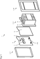
- FIG. 1 A preferred first embodiment of the LED light 1 according to the invention is shown schematically in an exploded representation.
- the LED light has a light housing 3, which is composed of a lens 17, a cooling device 12 and a frame 16.
- the cooling device 12 can be fixed on the lens 17 by means of the frame 16, in particular by means of a latching device.
- the LED light 1 has an LED light module 4 with a printed circuit board 8 designed as a load circuit board 9. A rear side of the load circuit board 9 can be seen in this view.
- a load simulation device 6 and a failure control device 7 are arranged on the rear side of the load circuit board 9. Between the LED light module 4 and the cooling device 12 there is a heat conducting device 13 for dissipating heat from the load simulation device 6 and the failure control device 7 to the cooling device 12.
- the cooling device 12 has a plurality of cooling fins 18.
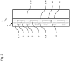
- Fig. 2 shows the LED light Fig. 1 in an assembled state schematically in a side view.
- the load simulation device 6 and the failure control device 7 are arranged on the back of the common printed circuit board 8 designed as a load circuit board 9.
- a plurality of LEDs 5 of the LED light module 4 are arranged on a front side of the load circuit board 9.
- a parting line 14 is formed, which is sealed by means of a casting compound 15.
- the heat-conducting device 13 which is preferably designed as a heat-conducting plate, contacts the load simulation device 6 and the failure control device 7.
- FIG. 3 A preferred second embodiment of the LED light 1 according to the invention is shown schematically in a side view.
- the preferred second embodiment differs from the first embodiment of the LED light 1 according to the invention in the features that the LEDs 5 of the LED light module 4 are arranged on a printed circuit board 8 designed as an LED printed circuit board 10.
- the load simulation device 6 and the failure control device 7 are arranged on a circuit board 8 designed as a load circuit board 9.
- a thermal insulator 11 in particular an insulating layer, is arranged between the LED circuit board 10 and the load circuit board 9. In this way, heat transfer from the load simulation device 6 and the failure control device 7 to the LED circuit board 10 is reduced, so that the LEDs 5 are exposed to less thermal stress.
- Fig. 4 shows a preferred embodiment of a vehicle 2 according to the invention schematically in a side view.
- the vehicle 2 is designed as a trailer and has an LED light 1 according to the invention designed as a rear light with an integrated turn signal light.
Landscapes
- Engineering & Computer Science (AREA)
- General Engineering & Computer Science (AREA)
- Physics & Mathematics (AREA)
- Microelectronics & Electronic Packaging (AREA)
- Optics & Photonics (AREA)
- Mechanical Engineering (AREA)
- Arrangement Of Elements, Cooling, Sealing, Or The Like Of Lighting Devices (AREA)
- Non-Portable Lighting Devices Or Systems Thereof (AREA)
Abstract
Description
- Die vorliegende Erfindung betrifft eine LED-Leuchte für ein Fahrzeug, insbesondere für einen Trailer. Ferner betrifft die Erfindung ein Fahrzeug, insbesondere einen Trailer, mit einer erfindungsgemäßen LED-Leuchte.
- Trailer weisen Rückleuchten auf, welche zumeist mittels eines Steuerkabels mit einem Zugfahrzeug elektrisch gekoppelt sind. Die Rückleuchten sind zur Bereitstellung unterschiedlicher Leuchtfunktionen ausgebildet. Leuchtfunktionen sind beispielsweise ein Rücklicht zum Markieren eines Hecks des Trailers, ein Bremslicht zum Anzeigen der Betätigung einer Bremse, ein Rückfahrlicht zum Anzeigen der Wahl eines Rückwärtsgangs des Zugfahrzeugs und ein Blinklicht zum Anzeigen einer Fahrtrichtungsänderungswahl des Zugfahrzeugs. Über das Steuerkabel sind die für die unterschiedlichen Leuchtfunktionen ausgebildeten Leuchtelemente der Rückleuchte gezielt mit Strom beaufschlagbar, und somit sind die einzelnen Leuchtfunktionen vom Zugfahrzeug aus steuerbar.
- Besonders verbreitet sind Rückleuchten, in welchen als austauschbare Leuchtmittel Glühlampen mit einer Glühwendel verbaut sind. Die Glühwendel ist in der Regel aus einem dünnen Wolframdraht hergestellt. Das Ansteuern derartiger Leuchtmittel erfolgt durch Bereitstellung eines elektrischen Stroms von dem Zugfahrzeug über das Steuerkabel. Moderne Rückleuchten weisen anstatt einer Glühlampe mit Glühwendel eine Vielzahl von LED-Leuchtmitteln auf, welche auf einer Leiterplatte angeordnet und somit zu einem LED-Leuchtmodul zusammengefasst sind. LED-Leuchtmittel haben den Vorteil einer wesentlich höheren Lebensdauer sowie eines geringeren Stromverbrauches aufgrund eines besseren Wirkungsgrads als Glühlampen mit Glühwendel.
- Da die Schnittstelle herkömmlicher Zugfahrzeuge zum Steuerkabel grundsätzlich auf Glühlampen mit Glühwendel ausgerichtet ist und LED-Leuchtmodule wesentlich geringere Leistungen als Glühlampen mit Glühwendel aufweisen, ist ein direkter Anschluss des LED-Leuchtmoduls an das Steuerkabel nicht möglich. Hierfür werden sogenannte Lastsimulationsvorrichtungen verwendet, welche am Zugfahrzeug oder Trailer angeordnet werden und eine elektrische Charakteristik einer Glühlampe mit Glühwendel simulieren. Hierzu zählen beispielsweise eine Leistung, eine Veränderung des Widerstands nach einem "Kaltstart" der Glühlampe oder dergleichen. Die Verlustleistung einer Lastsimulationsvorrichtung wird in Form von Wärme abgegeben, deshalb werden herkömmliche Lastsimulationsvorrichtungen üblicherweise an einer gut belüfteten Stelle am Zugfahrzeug oder Trailer angeordnet.
- Bekannte LED-Leuchten haben den Nachteil, dass diese nur sehr aufwendig sowie mit einer Vielzahl von Montageschritten montierbar sind. So sind beispielsweise relativ viele Kabelverbindungen bei der Montage herzustellen, wie beispielsweise eine Kabelverbindung zwischen dem Zugfahrzeug und der Lastsimulationsvorrichtung sowie zwischen der Lastsimulationsvorrichtung und dem LED-Leuchtmodul. Ein Nachrüsten eines Fahrzeugs von Leuchten mit Glühlampen auf LED-Leuchten ist daher verhältnismäßig teuer. Ferner hat die Vielzahl der erforderlichen Kabelverbindungen den Nachteil besonders vieler Fehlerquellen, die allesamt zum Funktionsausfall der LED-Leuchte führen können. Schließlich weisen derartige LED-Leuchten aufgrund der dezentralen Anordnungen einen besonders hohen Bauraumbedarf auf.
- Es ist daher die Aufgabe der vorliegenden Erfindung, eine LED-Leuchte für ein Fahrzeug sowie ein Fahrzeug mit einer LED-Leuchte bereitzustellen, welche die Nachteile des Standes der Technik nicht aufweisen oder zumindest teilweise nicht aufweisen. Es ist insbesondere die Aufgabe der vorliegenden Erfindung, eine LED-Leuchte sowie ein Fahrzeug zu schaffen, welche auf eine einfache Art und Weise sowie kostengünstig montierbar sind und/oder einen geringeren Bauraumbedarf aufweisen und/oder eine reduzierte Fehleranfälligkeit aufweisen.
- Voranstehende Aufgabe wird durch die Patentansprüche gelöst. Demnach wird die Aufgabe durch eine LED-Leuchte für ein Fahrzeug gemäß dem unabhängigen Anspruch 1 und durch ein Fahrzeug mit einer LED-Leuchte gemäß dem nebengeordneten Anspruch 10 gelöst.
- Gemäß einem ersten Aspekt der Erfindung wird die Aufgabe durch eine LED-Leuchte für ein Fahrzeug gelöst. Die LED-Leuchte weist ein Leuchtengehäuse und ein LED-Leuchtmodul mit einer Mehrzahl von LEDs auf. Das LED-Leuchtmodul ist innerhalb des Leuchtengehäuses angeordnet. Erfindungsgemäß weist die LED-Leuchte eine Lastsimulationsvorrichtung zum Simulieren einer elektrischen Charakteristik einer Glühbirne mit einer Glühwendel auf. Die Lastsimulationsvorrichtung ist am Leuchtengehäuse und/oder innerhalb des Leuchtengehäuses angeordnet. Die LED-Leuchte ist vorzugsweise als Rückleuchte, insbesondere für einen Trailer, ausgebildet.
- Das Leuchtengehäuse ist vorzugsweise mehrteilig ausgebildet. Das Leuchtengehäuse weist vorzugsweise eine Lichtscheibe, insbesondere aus einem lichtdurchlässigen Kunststoff, Glas oder dergleichen, auf. Vorzugsweise ist die Lichtscheibe napfförmig ausgebildet und weist eine Hauptfläche sowie mehrere, insbesondere vier, Seitenflächen auf. Vorzugsweise weist das Leuchtengehäuse eine Rückwand oder eine Rückwandvorrichtung zum Schließen des Leuchtengehäuses auf. Unter einer Rückwandanordnung wird beispielsweise eine Kombination aus einer Haltevorrichtung, insbesondere ein Halterahmen, und einer weiteren Komponente der LED-Leuchte verstanden, welche im Zusammenspiel eine Rückwand des Leuchtengehäuses substituieren. Die Rückwand bzw. Rückwandvorrichtung weist vorzugsweise eine Rastvorrichtung zum Verrasten an der Lichtscheibe und/oder dem LED-Leuchtmodul auf. Das Leuchtengehäuse ist vorzugsweise zur Aufnahme der übrigen Komponenten der LED-Leuchte, insbesondere des LED-Leuchtmoduls, ausgebildet. Ferner kann vorgesehen sein, dass eine oder mehrere Komponenten der LED-Leuchte, insbesondere witterungsbeständige Komponenten, einen Teil des Leuchtengehäuses bilden. Das Leuchtengehäuse ist vorzugsweise nach außen abgedichtet, um die darin angeordneten Komponenten der LED-Leuchte vor äußeren Einflüssen zu schützen.
- Das LED-Leuchtmodul weist vorzugsweise eine Leiterplatte auf, auf welcher die LEDs als sogenannte "surface mount devices" (SMD) angeordnet sind. Die Seite der Leiterplatte, an welcher die LEDs bzw. ein Großteil der LEDs angeordnet ist, wird im Rahmen der Erfindung auch als lichtemittierende Seite bezeichnet. Die LEDs können erfindungsgemäß als einfarbige und/oder mehrfarbige LEDs ausgebildet sein. Ein derartiges LED-Leuchtmodul kann auch als LED-Panel bezeichnet werden. Es kann erfindungsgemäß vorgesehen sein, dass das LED-Leuchtmodul in eine lichtdurchlässige Vergussmasse derart eingegossen ist, dass zumindest die lichtemittierende Seite der Leiterplatte, vorzugsweise inklusive der darauf angeordneten LEDs, von der Vergussmasse abgedeckt ist. Somit ist die lichtemittierende Seite vor äußeren Einflüssen, insbesondere Feuchtigkeit, Regen, Schnee, Schutz oder dergleichen, geschützt. In diesem Fall kann auf eine zusätzliche Lichtscheibe verzichtet werden, sodass das LED-Leuchtmodul mit Vergussmasse einen Teil des Leuchtengehäuses bildet. Hierdurch können die Herstellungskosten der LED-Leuchte reduziert werden.
- Die Lastsimulationsvorrichtung ist zum Simulieren der elektrischen Charakteristik einer Glühbirne mit einer Glühwendel, insbesondere im Zusammenspiel mit dem LED-Leuchtmodul, ausgebildet. Unter einer elektrischen Charakteristik wird beispielsweise ein elektrischer Widerstand, eine elektrische Leistung im Betrieb verstanden. Ein wichtiger Einflussfaktor hierauf ist beispielsweise eine jüngste Betriebshistorie der LED-Leuchte. Eine durch Benutzung bereits erwärmte Glühbirne weist einen höheren ohmschen Widerstand als eine kalte Glühbirne auf. Der ohmsche Widerstand einer kalten Glühbirne wird nach dem Beaufschlagen mit Strom rasch ansteigen und sich einem charakteristischen Grenzwert nähern. Ein solches Verhalten einer Glühbirne ist mittels der Lastsimulationsvorrichtung simulierbar. Hierfür weist die Lastsimulationsvorrichtung vorzugsweise einen oder mehrere Lastwiderstände auf, welche insbesondere als SMD Bauteile, beispielsweise als Widerstandsanordnung, auf einer Leiterplatte angeordnet sind. Die Lastsimulationsvorrichtung ist ebenfalls innerhalb des Leuchtengehäuses angeordnet.
- Eine erfindungsgemäße LED-Leuchte für ein Fahrzeug hat gegenüber herkömmlichen LED-Leuchten den Vorteil, dass durch die Integration der Lastsimulationsvorrichtung in die LED-Leuchte mit einfachen Mitteln sowie auf eine kostengünstige Art und Weise eine integrale LED-Leuchte bereitgestellt ist, welche leicht verbaubar sowie einfacher elektrisch anschließbar ist. Zudem benötigt die erfindungsgemäße LED-Leuchte einen geringeren Bauraum und weist aufgrund der geringeren erforderlichen Anzahl externer Verkabelungen eine verringerte Fehleranfälligkeit auf.
- Gemäß einer bevorzugten Weiterentwicklung der Erfindung kann bei einer LED-Leuchte vorgesehen sein, dass die LED-Leuchte eine Ausfallkontrollvorrichtung zum Detektieren sowie zum Melden eines Defekts des LED-Leuchtmoduls aufweist, wobei die Ausfallkontrollvorrichtung innerhalb des Leuchtengehäuses angeordnet ist. Die Ausfallkontrollvorrichtung ist vorzugsweise ausgebildet, bei Detektion eines vorgegebenen Fehlergrads des LED-Leuchtmoduls, wenn beispielsweise eine LED oder zwei LEDs ausgefallen sind, die LED-Leuchte oder zumindest ein LED-Leuchtmodul der LED-Leuchte abzuschalten, insbesondere zur Vermeidung von weiteren Beschädigungen durch Überspannungen, hohe Ströme, Überhitzungen oder dergleichen. Zudem ist die Ausfallkontrollvorrichtung vorzugsweise ausgebildet, den Detektierten Ausfall von LEDs oder dem LED-Leuchtmodul zu melden, beispielsweise über die Lastsimulationsvorrichtung. Daher ist es bevorzugt, dass die Lastsimulationsvorrichtung und die Ausfallkontrollvorrichtung gemeinsam eine funktionale Einheit bilden, insbesondere auf einer gemeinsamen Leiterplatte angeordnet sind. Die Lastsimulationsvorrichtung und/oder die Ausfallkontrollvorrichtung sind vorzugsweise ausgebildet, einen solchen Ausfall an eine Lichtsteuerung des Zugfahrzeugs weiterzuleiten, insbesondere an eine Warnleuchte, einen Warnsummer oder dergleichen.
- Es ist erfindungsgemäß bevorzugt, dass die Ausfallkontrollvorrichtung und das LED-Leuchtmodul auf einer gemeinsamen Leiterplatte angeordnet sind. Hierbei kann erfindungsgemäß vorgesehen sein, dass die LEDs auf einer Vorderseite der Leiterplatte und die Ausfallkontrollvorrichtung, insbesondere Komponenten der Ausfallkontrollvorrichtung, welche im Betrieb eine relativ hohe Wärmeentwicklung aufweisen, auf einer Rückseite der Leiterplatte als SMD angeordnet sind. Dies hat den Vorteil, dass ein Bauraumbedarf der LED-Leuchte aufgrund eines besonders kompakten Aufbaus sowie einer geringen Teileanzahl reduzierbar ist. Ferner sind elektrische Verbindungen zwischen den LEDs und der Ausfallkontrollvorrichtung über geätzte Leiterbahnen herstellbar, sodass keine zusätzlichen Kabel verwendet werden müssen.
- Weiter bevorzugt sind die Lastsimulationsvorrichtung und das LED-Leuchtmodul auf einer gemeinsamen Lastleiterplatte angeordnet. Insbesondere bevorzugt ist die Ausfallkontrollvorrichtung auf derselben Lastleiterplatte angeordnet. Hierbei kann erfindungsgemäß vorgesehen sein, dass die LEDs auf einer Vorderseite der Lastleiterplatte und die Lastsimulationsvorrichtung, insbesondere Komponenten der Lastsimulationsvorrichtung, welche im Betrieb eine relativ hohe Wärmeentwicklung aufweisen, auf einer Rückseite der Lastleiterplatte als SMD angeordnet sind. Dies hat den Vorteil, dass ein Bauraumbedarf der LED-Leuchte aufgrund eines besonders kompakten Aufbaus sowie einer geringen Teileanzahl reduzierbar ist. Ferner sind elektrische Verbindungen zwischen den LEDs und der Lastsimulationsvorrichtung und ggf. der Ausfallkontrollvorrichtung über geätzte Leiterbahnen herstellbar, sodass keine zusätzlichen Kabel verwendet werden müssen.
- In einer bevorzugten alternativen Ausgestaltung der Erfindung kann bei einer LED-Leuchte vorgesehen sein, dass die Lastsimulationsvorrichtung auf einer Lastleiterplatte und das LED-Leuchtmodul auf einer LED-Leiterplatte angeordnet ist, wobei zwischen der Lastleiterplatte und der LED-Leiterplatte ein thermischer Isolator angeordnet ist. Die Lastleiterplatte und die LED-Leiterplatte sind vorzugsweise als separate Leiterplatten ausgebildet. Ferner sind die Lastleiterplatte und die LED-Leiterplatte vorzugsweise parallel zueinander sowie voneinander beabstandet angeordnet. Der thermische Isolator ist vorzugsweise als thermische Isolationsschicht, insbesondere aus einem thermisch dämmenden Material, insbesondere einem porösen, geschäumten oder zellstoffartig aufgebauten Material, ausgebildet. Der thermische Isolator weist daher vorzugsweise einen besonders niedrigen Wärmeleitkoeffizienten, wie beispielsweise PUR, EPS, Mineralwolle oder dergleichen, auf. Der thermische Isolator, ist zwischen der Lastleiterplatte und der LED-Leiterplatte, insbesondere in einer Sandwichanordnung, angeordnet. Ein derartiger Aufbau hat den Vorteil, dass eine Wärmetrennung zwischen der Lastsimulationsvorrichtung und dem LED-Leuchtmodul verbessert ist. Das Risiko des Beschädigens des LED-Leuchtmoduls durch die Abwärme der Lastsimulationsvorrichtung ist somit kostengünstig sowie auf eine einfache Art und Weise reduzierbar.
- Vorzugsweise weist die LED-Leuchte eine Kühlvorrichtung zum Kühlen der LED-Leuchte auf, wobei die Kühlvorrichtung mit der Lastleiterplatte thermisch leitend gekoppelt ist. Die Kühlvorrichtung kann beispielsweise direkt an die Lastleiterplatte angebunden sein, insbesondere durch direktes Kontaktieren, insbesondere von Lastwiderständen der Lastsimulationsvorrichtung, da an diesen im Betrieb besonders viel Wärme erzeugt wird. Die Kühlvorrichtung weist vorzugsweise eine Mehrzahl von Kühlrippen auf, welche sich von der Lastleiterplatte weg erstrecken. Weiter bevorzugt weist die Kühlvorrichtung eine der Lastleiterplatte zugewandte Kühlfläche auf, welche eine möglichst große Kontaktfläche zur Lastleiterplatte bzw. zumindest zu den Lastwiderständen, bereitstellt. Vorzugsweise sind die Kühlvorrichtung und die Lichtscheibe ausgebildet, miteinander zu verrasten. Hierfür weisen die Kühlvorrichtung und/oder die Lichtscheibe Rastelemente auf, welche mit entsprechenden Rastaufnahmen der Lichtscheibe bzw. der Kühlvorrichtung kooperieren. Eine Kühlvorrichtung hat den Vorteil, dass insbesondere von der Lastsimulationsvorrichtung produzierte Wärme von dem LED-Leuchtmoduls wegführbar ist, sodass ein Überhitzen des LED-Leuchtmoduls besser vermeidbar ist.
- Es kann erfindungsgemäß vorgesehen sein, dass die Kühlvorrichtung über eine Wärmeleitvorrichtung mit der Lastleiterplatte, insbesondere mit einer Rückseite der Lastleiterplatte, thermisch leitend gekoppelt ist. Unter einer thermisch leitenden Kopplung mit der Lastleiterplatte wird erfindungsgemäß auch eine thermische leitende Kopplung mit den auf der Lastleiterplatte angeordneten SMD-Bauteilen, wie beispielsweise den Lastwiderständen der Lastsimulationsvorrichtung, verstanden. Bei einer Sandwichanordnung mit einer LED-Leiterplatte und einer Lastleiterplatte kann auch vorgesehen sein, dass die Wärmeleitvorrichtung die Lastleiterplatte umgibt, wobei der thermische Isolator vorzugsweise zwischen der Wärmeleitvorrichtung und der LED-Leiterplatte angeordnet ist. Die Wärmeleitvorrichtung ist vorzugsweise als Wärmeleitplatte, Wärmeleitkissen oder Wärmeleitgel ausgebildet. Zudem kann die Wärmeleitvorrichtung als von der Kühlvorrichtung separate Wärmeleitvorrichtung oder als in die Kühlvorrichtung integrierte Wärmeleitvorrichtung ausgebildet sein. Die Wärmeleitvorrichtung weist vorzugsweise einen besonders hohen Wärmeleitkoeffizienten, wie beispielsweise Kupfer, Silber oder dergleichen, auf. Die Wärmeleitvorrichtung ist weiter bevorzugt ausgebildet, sich einer Kontur der Rückseite der Lastleiterplatte bzw. der Lastsimulationsvorrichtung anzupassen, sodass eine Kontaktfläche zwischen Wärmeleitvorrichtung und der Rückseite der bestückten Lastleiterplatte vergrößerbar ist. Eine Wärmeleitvorrichtung hat den Vorteil, dass eine Wärmeabgabe von der Lastleiterplatte an die Kühlungsvorrichtung und somit eine Kühlung der Lastleiterplatte sowie der darauf angeordneten SMD-Bauteile verbessert ist.
- Gemäß einer vorteilhaften Ausführungsform der Erfindung bildet die Kühlvorrichtung einen ersten Teilbereich des Leuchtengehäuses, wobei eine Trennfuge zwischen der Kühlvorrichtung und einem zweiten Teilbereich des Leuchtengehäuses mittels einer Vergussmasse abgedichtet ist. Der zweite Teilbereich des Leuchtengehäuses kann beispielsweise durch einen Rahmen gebildet sein, welcher zum Halten der Kühlvorrichtung an der Lichtscheibe ausgebildet ist, insbesondere über eine Rastvorrichtung. Trennfugen zwischen dem Rahmen und der Lichtscheibe sind vorzugsweise mittels einer Gummi- und/oder Silikondichtung abgedichtet. Eine derartige LED-Leuchte ist einfach aufgebaut und mit einfachen Mitteln sowie kostengünstig herstellbar.
- Es ist bevorzugt, dass die LED-Leuchte als LED-Rückleuchte und/oder LED-Blinkleuchte ausgebildet ist. Eine als LED-Rückleuchte ausgebildete LED-Leuchte ist vorzugsweise zum Erzeugen eines, insbesondere weißen, Rückwärtsganglichts und/oder eines, insbesondere roten, Rücklichts und/oder eines, insbesondere roten, Nebelschlusslichts und/oder eines, insbesondere roten Bremslichts, ausgebildet. Dabei kann vorgesehen ein Die LED-Leuchte für einzelne Lichtarten mehrere LED-Leuchtmodule aufweist. Die LED-Leuchtmodule sind vorzugsweise auf einer gemeinsamen Leiterplatte angeordnet. Zudem kann erfindungsgemäß vorgesehen sein, dass die LED-Leuchte eine gemeinsame Ausfallkontrollvorrichtung oder separate Ausfallkontrollvorrichtungen für die LED-Leuchtmodule aufweist. Ebenso ist es bevorzugt, dass die LED für jedes LED-Leuchtmodul eine eigene Lastsimulationsvorrichtung oder für die Gesamtheit der LED-Leuchtmodule eine gemeinsame Lastsimulationsvorrichtung aufweist.
- Gemäß einem zweiten Aspekt der Erfindung wird die Aufgabe durch ein Fahrzeug mit einer erfindungsgemäßen LED-Leuchte gelöst. Das Fahrzeug ist vorzugsweise als Trailer ausgebildet.
- Bei dem erfindungsgemäßen Fahrzeug mit einer erfindungsgemäßen LED-Leuchte ergeben sich sämtliche Vorteile, die bereits zu einer LED-Leuchte für ein Fahrzeug gemäß dem ersten Aspekt der Erfindung beschrieben worden sind. Demnach hat das erfindungsgemäße Fahrzeug gegenüber herkömmlichen Fahrzeugen den Vorteil, dass dieses eine LED-Leuchte aufweist, welche durch die Integration der Lastsimulationsvorrichtung mit einfachen Mitteln sowie auf eine kostengünstige Art herstellbar sowie an dem Fahrzeug verbaubar ist. Zudem wird aufgrund der Integration der Lastsimulationsvorrichtung in die LED-Leuchte ein geringerer Bauraum am Fahrzeug beansprucht. Ein Austausch der LED-Leuchte ist insbesondere aufgrund der reduzierten Anzahl elektrischer Anschlüsse wesentlich erleichtert. Aufgrund der geringeren erforderlichen Anzahl externer Verkabelungen weist die LED-Leuchte des Fahrzeugs eine verringerte Fehleranfälligkeit auf.
- Anhand der beigefügten Zeichnungen wird die Erfindung nachfolgend näher erläutert. Es zeigen jeweils schematisch:
- Fig. 1
- in einer explodierten Darstellung eine bevorzugte erste Ausführungsform der erfindungsgemäßen LED-Leuchte,
- Fig. 2
- in einer Seitenansicht die LED-Leuchte aus
Figur 1 in einem zusammengebauten Zustand, - Fig. 3
- in einer Seitenansicht eine bevorzugte erste Ausführungsform der erfindungsgemäßen LED-Leuchte in einem zusammengebauten Zustand, und
- Fig. 4
- in einer Seitenansicht eine bevorzugte Ausführungsform eines erfindungsgemäßen Fahrzeugs.
- Elemente mit gleicher Funktion und Wirkungsweise sind in den
Fig. 1 bis 4 jeweils mit denselben Bezugszeichen versehen. - In
Fig. 1 ist eine bevorzugte erste Ausführungsform der erfindungsgemäßen LED-Leuchte 1 schematisch in einer explodierten Darstellung abgebildet. Die LED-Leuchte weist ein Leuchtengehäuse 3 auf, welches sich aus einer Lichtscheibe 17, einer Kühlvorrichtung 12 und einem Rahmen 16 zusammensetzt. Mittels des Rahmens 16 ist die Kühlvorrichtung 12 an der Lichtscheibe 17 fixierbar, insbesondere mittels einer Rastvorrichtung. Die LED-Leuchte 1 weist ein LED-Leuchtmodul 4 mit einer als Lastleiterplatte 9 ausgebildeten Leiterplatte 8 auf. In dieser Ansicht ist eine Rückseite der Lastleiterplatte 9 erkennbar. An der Rückseite der Lastleiterplatte 9 sind eine Lastsimulationsvorrichtung 6 sowie eine Ausfallkontrollvorrichtung 7 angeordnet. Zwischen dem LED-Leuchtmodul 4 und der Kühlvorrichtung 12 ist eine Wärmeleitvorrichtung 13 zum Ableiten von Wärme von der Lastsimulationsvorrichtung 6 sowie der Ausfallkontrollvorrichtung 7 zur Kühlvorrichtung 12. Die Kühlvorrichtung 12 weist mehrere Kühlrippen 18 auf. -
Fig. 2 zeigt die LED-Leuchte ausFig. 1 in einem zusammengebauten Zustand schematisch in einer Seitenansicht. In dieser Ansicht ist erkennbar, dass die Lastsimulationsvorrichtung 6 und die Ausfallkontrollvorrichtung 7 auf der Rückseite der gemeinsamen als Lastleiterplatte 9 ausgebildeten Leiterplatte 8 angeordnet sind. Auf einer Vorderseite der Lastleiterplatte 9 sind mehrere LEDs 5 des LED-Leuchtmoduls 4 angeordnet. Zwischen dem Rahmen 16 und der Kühlvorrichtung 12 ist eine Trennfuge 14 ausgebildet, welche mittels einer Vergussmasse 15 abgedichtet ist. In diesem zusammengebauten Zustand kontaktiert die, vorzugsweise als Wärmeleitplatte ausgebildete, Wärmeleitvorrichtung 13 die Lastsimulationsvorrichtung 6 und die Ausfallkontrollvorrichtung 7. - In
Fig. 3 ist eine bevorzugte zweite Ausführungsform der erfindungsgemäßen LED-Leuchte 1 schematisch in einer Seitenansicht abgebildet. Die bevorzugte zweite Ausführungsform unterscheidet sich von der ersten Ausführungsform der erfindungsgemäßen LED-Leuchte 1 in den Merkmalen, dass die LEDs 5 des LED-Leuchtmoduls 4 auf einer als LED-Leiterplatte 10 ausgebildeten Leiterplatte 8 angeordnet sind. Die Lastsimulationsvorrichtung 6 und die Ausfallkontrollvorrichtung 7 sind auf einer als Lastleiterplatte 9 ausgebildeten Leiterplatte 8 angeordnet. Zwischen der LED-Leiterplatte 10 und der Lastleiterplatte 9 ist ein thermischer Isolator 11, insbesondere eine Dämmschicht, angeordnet. Auf diese Weise ist ein Wärmeübergang von der Lastsimulationsvorrichtung 6 und der Ausfallkontrollvorrichtung 7 auf die LED-Leiterplatte 10 reduziert, sodass die LEDs 5 einer geringeren thermischen Beanspruchung ausgesetzt sind. -
Fig. 4 zeigt eine bevorzugte Ausführungsform eines erfindungsgemäßen Fahrzeugs 2 schematisch in einer Seitenansicht. Das Fahrzeug 2 ist als Trailer ausgebildet und weist eine als Rückleuchte mit integrierter Blinkleuchte ausgebildete erfindungsgemäße LED-Leuchte 1 auf. -
- 1
- LED-Leuchte
- 2
- Fahrzeug
- 3
- Leuchtengehäuse
- 4
- LED-Leuchtmodul
- 5
- LED
- 6
- Lastsimulationsvorrichtung
- 7
- Ausfallkontrollvorrichtung
- 8
- Leiterplatte
- 9
- Lastleiterplatte
- 10
- LED-Leiterplatte
- 11
- thermischer Isolator
- 12
- Kühlvorrichtung
- 13
- Wärmeleitvorrichtung
- 14
- Trennfuge
- 15
- Vergussmasse
- 16
- Rahmen
- 17
- Lichtscheibe
- 18
- Kühlrippe
Claims (10)
- LED-Leuchte (1) für ein Fahrzeug (2), aufweisend ein Leuchtengehäuse (3) und ein LED-Leuchtmodul (4) mit einer Mehrzahl von LEDs (5), wobei das LED-Leuchtmodul (4) innerhalb des Leuchtengehäuses (3) angeordnet ist, dadurch gekennzeichnet, dass
die LED-Leuchte (1) eine Lastsimulationsvorrichtung (6) zum Simulieren einer elektrischen Charakteristik einer Glühbirne mit einer Glühwendel aufweist, wobei die Lastsimulationsvorrichtung (6) am Leuchtengehäuse (3) und/oder innerhalb des Leuchtengehäuses (3) angeordnet ist. - LED-Leuchte (1) nach Anspruch 1,
dadurch gekennzeichnet, dass
die LED-Leuchte (1) eine Ausfallkontrollvorrichtung (7) zum Detektieren sowie zum Melden eines Defekts des LED-Leuchtmoduls (4) aufweist, wobei die Ausfallkontrollvorrichtung (7) innerhalb des Leuchtengehäuses (3) angeordnet ist. - LED-Leuchte (1) nach Anspruch 2,
dadurch gekennzeichnet, dass
die Ausfallkontrollvorrichtung (7) und das LED-Leuchtmodul (4) auf einer gemeinsamen Leiterplatte (8) angeordnet sind. - LED-Leuchte (1) nach einem der vorangegangenen Ansprüche,
dadurch gekennzeichnet, dass
die Lastsimulationsvorrichtung (6) und das LED-Leuchtmodul (4) auf einer gemeinsamen Lastleiterplatte (9) angeordnet sind. - LED-Leuchte (1) nach einem der Ansprüche 1 bis 3,
dadurch gekennzeichnet, dass
die Lastsimulationsvorrichtung (6) auf einer Lastleiterplatte (9) und das LED-Leuchtmodul (4) auf einer LED-Leiterplatte (10) angeordnet ist, wobei zwischen der Lastleiterplatte (9) und der LED-Leiterplatte (10) ein thermischer Isolator (11) angeordnet ist. - LED-Leuchte (1) nach Anspruch 4 oder 5,
dadurch gekennzeichnet, dass
die LED-Leuchte (1) eine Kühlvorrichtung (12) zum Kühlen der LED-Leuchte (1) aufweist, wobei die Kühlvorrichtung (12) mit der Lastleiterplatte (9) thermisch leitend gekoppelt ist. - LED-Leuchte (1) nach Anspruch 6,
dadurch gekennzeichnet, dass
die Kühlvorrichtung (12) über eine Wärmeleitvorrichtung (13) mit der Lastleiterplatte (9) thermisch leitend gekoppelt ist. - LED-Leuchte (1) nach Anspruch 7,
dadurch gekennzeichnet, dass
die Kühlvorrichtung (12) einen ersten Teilbereich des Leuchtengehäuses (3) bildet, wobei eine Trennfuge (14) zwischen der Kühlvorrichtung (12) und einem zweiten Teilbereich des Leuchtengehäuses (3) mittels einer Vergussmasse (15) abgedichtet ist. - LED-Leuchte (1) nach einem der vorangegangenen Ansprüche,
dadurch gekennzeichnet, dass
die LED-Leuchte (1) als LED-Rückleuchte und/oder LED-Blinkleuchte ausgebildet ist. - Fahrzeug (2),
dadurch gekennzeichnet, dass
das Fahrzeug (2) eine LED-Leuchte (1) nach einem der Ansprüche 1 bis 9 aufweist.
Priority Applications (1)
| Application Number | Priority Date | Filing Date | Title |
|---|---|---|---|
| PL19185671T PL3594556T3 (pl) | 2018-07-13 | 2019-07-11 | Lampa LED do pojazdu i pojazd z lampą LED |
Applications Claiming Priority (1)
| Application Number | Priority Date | Filing Date | Title |
|---|---|---|---|
| DE102018117057.2A DE102018117057A1 (de) | 2018-07-13 | 2018-07-13 | LED-Leuchte für ein Fahrzeug und Fahrzeug mit einer LED-Leuchte |
Publications (2)
| Publication Number | Publication Date |
|---|---|
| EP3594556A1 true EP3594556A1 (de) | 2020-01-15 |
| EP3594556B1 EP3594556B1 (de) | 2021-08-25 |
Family
ID=67437664
Family Applications (1)
| Application Number | Title | Priority Date | Filing Date |
|---|---|---|---|
| EP19185671.5A Active EP3594556B1 (de) | 2018-07-13 | 2019-07-11 | Led-leuchte für ein fahrzeug und fahrzeug mit einer led-leuchte |
Country Status (4)
| Country | Link |
|---|---|
| EP (1) | EP3594556B1 (de) |
| DE (1) | DE102018117057A1 (de) |
| ES (1) | ES2891573T3 (de) |
| PL (1) | PL3594556T3 (de) |
Cited By (2)
| Publication number | Priority date | Publication date | Assignee | Title |
|---|---|---|---|---|
| FR3129706A1 (fr) * | 2021-11-30 | 2023-06-02 | Valeo Vision | Dispositif lumineux pour un véhicule automobile comprenant une matrice d'éléments électroluminescents |
| FR3129705A1 (fr) * | 2021-11-30 | 2023-06-02 | Valeo Vision | Dispositif lumineux pour un véhicule automobile comprenant une matrice d'éléments électroluminescents |
Citations (3)
| Publication number | Priority date | Publication date | Assignee | Title |
|---|---|---|---|---|
| WO2009037053A1 (de) * | 2007-09-19 | 2009-03-26 | Osram Gesellschaft mit beschränkter Haftung | Scheinwerferlampe und deren verwendung |
| WO2013014580A1 (en) * | 2011-07-22 | 2013-01-31 | Koninklijke Philips Electronics N.V. | Light emitting diode driver with non-destructive circuit for indicating fault or outage of light emitting diode load |
| DE102014019475A1 (de) * | 2014-12-23 | 2016-06-23 | Db Netz Ag | Leuchtvorrichtung für eine Lichtsignalanlage des schienengebundenen Verkehrs |
-
2018
- 2018-07-13 DE DE102018117057.2A patent/DE102018117057A1/de not_active Withdrawn
-
2019
- 2019-07-11 PL PL19185671T patent/PL3594556T3/pl unknown
- 2019-07-11 EP EP19185671.5A patent/EP3594556B1/de active Active
- 2019-07-11 ES ES19185671T patent/ES2891573T3/es active Active
Patent Citations (3)
| Publication number | Priority date | Publication date | Assignee | Title |
|---|---|---|---|---|
| WO2009037053A1 (de) * | 2007-09-19 | 2009-03-26 | Osram Gesellschaft mit beschränkter Haftung | Scheinwerferlampe und deren verwendung |
| WO2013014580A1 (en) * | 2011-07-22 | 2013-01-31 | Koninklijke Philips Electronics N.V. | Light emitting diode driver with non-destructive circuit for indicating fault or outage of light emitting diode load |
| DE102014019475A1 (de) * | 2014-12-23 | 2016-06-23 | Db Netz Ag | Leuchtvorrichtung für eine Lichtsignalanlage des schienengebundenen Verkehrs |
Cited By (4)
| Publication number | Priority date | Publication date | Assignee | Title |
|---|---|---|---|---|
| FR3129706A1 (fr) * | 2021-11-30 | 2023-06-02 | Valeo Vision | Dispositif lumineux pour un véhicule automobile comprenant une matrice d'éléments électroluminescents |
| FR3129705A1 (fr) * | 2021-11-30 | 2023-06-02 | Valeo Vision | Dispositif lumineux pour un véhicule automobile comprenant une matrice d'éléments électroluminescents |
| WO2023099507A1 (fr) * | 2021-11-30 | 2023-06-08 | Valeo Vision | Dispositif lumineux pour un véhicule automobile comprenant une matrice d'éléments électroluminescents |
| WO2023099506A1 (fr) * | 2021-11-30 | 2023-06-08 | Valeo Vision | Dispositif lumineux pour un véhicule automobile comprenant une matrice d'éléments électroluminescents |
Also Published As
| Publication number | Publication date |
|---|---|
| PL3594556T3 (pl) | 2022-01-24 |
| DE102018117057A1 (de) | 2020-01-16 |
| ES2891573T3 (es) | 2022-01-28 |
| EP3594556B1 (de) | 2021-08-25 |
Similar Documents
| Publication | Publication Date | Title |
|---|---|---|
| EP1719189B1 (de) | Leuchtdioden-anordnung für eine hochleistungs-leuchtdiode und verfahren zur herstellung einer leuchtdioden-anordnung | |
| DE19511755C1 (de) | Multiplex-Steuerung von Komponenten bzw. Untersystemen in Kraftfahrzeugen | |
| EP2000359B1 (de) | Schaltungsanordung | |
| EP2000358B1 (de) | Schaltungsanordnung zur Versorgung von Leuchtdioden in einem Anhänger | |
| DE102008031256A1 (de) | Beleuchtungseinheit für Fahrzeugscheinwerfer und Fahrzeugscheinwerfer | |
| EP3594556B1 (de) | Led-leuchte für ein fahrzeug und fahrzeug mit einer led-leuchte | |
| DE102010039012A1 (de) | LED-Lampe | |
| EP3210444B1 (de) | Kraftfahrzeug-aussenleuchte | |
| DE2105213A1 (de) | Elektrische Stromversorgungsvor richtung | |
| DE102008031262A1 (de) | Beleuchtungseinheit für Fahrzeugscheinwerfer und Fahrzeugscheinwerfer | |
| ITTO960453A1 (it) | Integrazione elettronica in cassette di servizi. | |
| EP1164816B1 (de) | Luftzuheizer | |
| DE202006020926U1 (de) | Leuchte | |
| EP1604865B1 (de) | Beleuchtungseinrichtung für ein Fahrzeug umfassend einen Sensor | |
| EP2603957B1 (de) | Rückseitige anbindung von led-modulen | |
| EP2415333B1 (de) | Betriebsmittel mit integrierter kühlplatte | |
| WO2017216019A1 (de) | Leuchte für fahrzeuge | |
| EP2783915B1 (de) | Verfahren zur Erzeugung eines Diagnosesignals einer Kraftfahrzeugleuchte mit mehreren Leuchtmitteln sowie Kraftfahrzeugleuchte | |
| DE102011077658A1 (de) | Beleuchtungsvorrichtung mit verbesserter Wärmeableitungsfähigkeit | |
| EP1467140A2 (de) | Signalgerät | |
| CN1268926A (zh) | 配电控制系统 | |
| DE102004062583B4 (de) | Leuchte für ein Kraftfahrzeug mit lichtemittierender Diode | |
| DE102020100742A1 (de) | Leiterplatte, Lichtmodul, Beleuchtungseinrichtung und Kraftfahrzeug | |
| EP4106496A1 (de) | Laststeuervorrichtung für kraftfahrzeugleuchten und entsprechender bausatz und verfahren | |
| DE102008040480A1 (de) | Halbleitermodul |
Legal Events
| Date | Code | Title | Description |
|---|---|---|---|
| PUAI | Public reference made under article 153(3) epc to a published international application that has entered the european phase |
Free format text: ORIGINAL CODE: 0009012 |
|
| STAA | Information on the status of an ep patent application or granted ep patent |
Free format text: STATUS: THE APPLICATION HAS BEEN PUBLISHED |
|
| AK | Designated contracting states |
Kind code of ref document: A1 Designated state(s): AL AT BE BG CH CY CZ DE DK EE ES FI FR GB GR HR HU IE IS IT LI LT LU LV MC MK MT NL NO PL PT RO RS SE SI SK SM TR |
|
| AX | Request for extension of the european patent |
Extension state: BA ME |
|
| STAA | Information on the status of an ep patent application or granted ep patent |
Free format text: STATUS: REQUEST FOR EXAMINATION WAS MADE |
|
| 17P | Request for examination filed |
Effective date: 20200122 |
|
| RBV | Designated contracting states (corrected) |
Designated state(s): AL AT BE BG CH CY CZ DE DK EE ES FI FR GB GR HR HU IE IS IT LI LT LU LV MC MK MT NL NO PL PT RO RS SE SI SK SM TR |
|
| STAA | Information on the status of an ep patent application or granted ep patent |
Free format text: STATUS: EXAMINATION IS IN PROGRESS |
|
| 17Q | First examination report despatched |
Effective date: 20201022 |
|
| GRAP | Despatch of communication of intention to grant a patent |
Free format text: ORIGINAL CODE: EPIDOSNIGR1 |
|
| STAA | Information on the status of an ep patent application or granted ep patent |
Free format text: STATUS: GRANT OF PATENT IS INTENDED |
|
| INTG | Intention to grant announced |
Effective date: 20210512 |
|
| GRAS | Grant fee paid |
Free format text: ORIGINAL CODE: EPIDOSNIGR3 |
|
| GRAA | (expected) grant |
Free format text: ORIGINAL CODE: 0009210 |
|
| STAA | Information on the status of an ep patent application or granted ep patent |
Free format text: STATUS: THE PATENT HAS BEEN GRANTED |
|
| AK | Designated contracting states |
Kind code of ref document: B1 Designated state(s): AL AT BE BG CH CY CZ DE DK EE ES FI FR GB GR HR HU IE IS IT LI LT LU LV MC MK MT NL NO PL PT RO RS SE SI SK SM TR |
|
| REG | Reference to a national code |
Ref country code: CH Ref legal event code: EP |
|
| REG | Reference to a national code |
Ref country code: IE Ref legal event code: FG4D Free format text: LANGUAGE OF EP DOCUMENT: GERMAN Ref country code: AT Ref legal event code: REF Ref document number: 1424152 Country of ref document: AT Kind code of ref document: T Effective date: 20210915 |
|
| REG | Reference to a national code |
Ref country code: DE Ref legal event code: R096 Ref document number: 502019002115 Country of ref document: DE |
|
| REG | Reference to a national code |
Ref country code: LT Ref legal event code: MG9D |
|
| REG | Reference to a national code |
Ref country code: NL Ref legal event code: MP Effective date: 20210825 |
|
| REG | Reference to a national code |
Ref country code: ES Ref legal event code: FG2A Ref document number: 2891573 Country of ref document: ES Kind code of ref document: T3 Effective date: 20220128 |
|
| PG25 | Lapsed in a contracting state [announced via postgrant information from national office to epo] |
Ref country code: FI Free format text: LAPSE BECAUSE OF FAILURE TO SUBMIT A TRANSLATION OF THE DESCRIPTION OR TO PAY THE FEE WITHIN THE PRESCRIBED TIME-LIMIT Effective date: 20210825 Ref country code: RS Free format text: LAPSE BECAUSE OF FAILURE TO SUBMIT A TRANSLATION OF THE DESCRIPTION OR TO PAY THE FEE WITHIN THE PRESCRIBED TIME-LIMIT Effective date: 20210825 Ref country code: SE Free format text: LAPSE BECAUSE OF FAILURE TO SUBMIT A TRANSLATION OF THE DESCRIPTION OR TO PAY THE FEE WITHIN THE PRESCRIBED TIME-LIMIT Effective date: 20210825 Ref country code: BG Free format text: LAPSE BECAUSE OF FAILURE TO SUBMIT A TRANSLATION OF THE DESCRIPTION OR TO PAY THE FEE WITHIN THE PRESCRIBED TIME-LIMIT Effective date: 20211125 Ref country code: LT Free format text: LAPSE BECAUSE OF FAILURE TO SUBMIT A TRANSLATION OF THE DESCRIPTION OR TO PAY THE FEE WITHIN THE PRESCRIBED TIME-LIMIT Effective date: 20210825 Ref country code: PT Free format text: LAPSE BECAUSE OF FAILURE TO SUBMIT A TRANSLATION OF THE DESCRIPTION OR TO PAY THE FEE WITHIN THE PRESCRIBED TIME-LIMIT Effective date: 20211227 Ref country code: NO Free format text: LAPSE BECAUSE OF FAILURE TO SUBMIT A TRANSLATION OF THE DESCRIPTION OR TO PAY THE FEE WITHIN THE PRESCRIBED TIME-LIMIT Effective date: 20211125 Ref country code: HR Free format text: LAPSE BECAUSE OF FAILURE TO SUBMIT A TRANSLATION OF THE DESCRIPTION OR TO PAY THE FEE WITHIN THE PRESCRIBED TIME-LIMIT Effective date: 20210825 |
|
| PG25 | Lapsed in a contracting state [announced via postgrant information from national office to epo] |
Ref country code: LV Free format text: LAPSE BECAUSE OF FAILURE TO SUBMIT A TRANSLATION OF THE DESCRIPTION OR TO PAY THE FEE WITHIN THE PRESCRIBED TIME-LIMIT Effective date: 20210825 Ref country code: GR Free format text: LAPSE BECAUSE OF FAILURE TO SUBMIT A TRANSLATION OF THE DESCRIPTION OR TO PAY THE FEE WITHIN THE PRESCRIBED TIME-LIMIT Effective date: 20211126 |
|
| PG25 | Lapsed in a contracting state [announced via postgrant information from national office to epo] |
Ref country code: NL Free format text: LAPSE BECAUSE OF FAILURE TO SUBMIT A TRANSLATION OF THE DESCRIPTION OR TO PAY THE FEE WITHIN THE PRESCRIBED TIME-LIMIT Effective date: 20210825 |
|
| PG25 | Lapsed in a contracting state [announced via postgrant information from national office to epo] |
Ref country code: DK Free format text: LAPSE BECAUSE OF FAILURE TO SUBMIT A TRANSLATION OF THE DESCRIPTION OR TO PAY THE FEE WITHIN THE PRESCRIBED TIME-LIMIT Effective date: 20210825 |
|
| REG | Reference to a national code |
Ref country code: DE Ref legal event code: R097 Ref document number: 502019002115 Country of ref document: DE |
|
| PG25 | Lapsed in a contracting state [announced via postgrant information from national office to epo] |
Ref country code: SM Free format text: LAPSE BECAUSE OF FAILURE TO SUBMIT A TRANSLATION OF THE DESCRIPTION OR TO PAY THE FEE WITHIN THE PRESCRIBED TIME-LIMIT Effective date: 20210825 Ref country code: SK Free format text: LAPSE BECAUSE OF FAILURE TO SUBMIT A TRANSLATION OF THE DESCRIPTION OR TO PAY THE FEE WITHIN THE PRESCRIBED TIME-LIMIT Effective date: 20210825 Ref country code: RO Free format text: LAPSE BECAUSE OF FAILURE TO SUBMIT A TRANSLATION OF THE DESCRIPTION OR TO PAY THE FEE WITHIN THE PRESCRIBED TIME-LIMIT Effective date: 20210825 Ref country code: EE Free format text: LAPSE BECAUSE OF FAILURE TO SUBMIT A TRANSLATION OF THE DESCRIPTION OR TO PAY THE FEE WITHIN THE PRESCRIBED TIME-LIMIT Effective date: 20210825 Ref country code: CZ Free format text: LAPSE BECAUSE OF FAILURE TO SUBMIT A TRANSLATION OF THE DESCRIPTION OR TO PAY THE FEE WITHIN THE PRESCRIBED TIME-LIMIT Effective date: 20210825 Ref country code: AL Free format text: LAPSE BECAUSE OF FAILURE TO SUBMIT A TRANSLATION OF THE DESCRIPTION OR TO PAY THE FEE WITHIN THE PRESCRIBED TIME-LIMIT Effective date: 20210825 |
|
| PLBE | No opposition filed within time limit |
Free format text: ORIGINAL CODE: 0009261 |
|
| STAA | Information on the status of an ep patent application or granted ep patent |
Free format text: STATUS: NO OPPOSITION FILED WITHIN TIME LIMIT |
|
| 26N | No opposition filed |
Effective date: 20220527 |
|
| PG25 | Lapsed in a contracting state [announced via postgrant information from national office to epo] |
Ref country code: SI Free format text: LAPSE BECAUSE OF FAILURE TO SUBMIT A TRANSLATION OF THE DESCRIPTION OR TO PAY THE FEE WITHIN THE PRESCRIBED TIME-LIMIT Effective date: 20210825 |
|
| PG25 | Lapsed in a contracting state [announced via postgrant information from national office to epo] |
Ref country code: MC Free format text: LAPSE BECAUSE OF FAILURE TO SUBMIT A TRANSLATION OF THE DESCRIPTION OR TO PAY THE FEE WITHIN THE PRESCRIBED TIME-LIMIT Effective date: 20210825 |
|
| REG | Reference to a national code |
Ref country code: CH Ref legal event code: PL |
|
| REG | Reference to a national code |
Ref country code: BE Ref legal event code: MM Effective date: 20220731 |
|
| PG25 | Lapsed in a contracting state [announced via postgrant information from national office to epo] |
Ref country code: LU Free format text: LAPSE BECAUSE OF NON-PAYMENT OF DUE FEES Effective date: 20220711 Ref country code: LI Free format text: LAPSE BECAUSE OF NON-PAYMENT OF DUE FEES Effective date: 20220731 Ref country code: CH Free format text: LAPSE BECAUSE OF NON-PAYMENT OF DUE FEES Effective date: 20220731 |
|
| PG25 | Lapsed in a contracting state [announced via postgrant information from national office to epo] |
Ref country code: BE Free format text: LAPSE BECAUSE OF NON-PAYMENT OF DUE FEES Effective date: 20220731 |
|
| PG25 | Lapsed in a contracting state [announced via postgrant information from national office to epo] |
Ref country code: IE Free format text: LAPSE BECAUSE OF NON-PAYMENT OF DUE FEES Effective date: 20220711 |
|
| GBPC | Gb: european patent ceased through non-payment of renewal fee |
Effective date: 20230711 |
|
| PG25 | Lapsed in a contracting state [announced via postgrant information from national office to epo] |
Ref country code: HU Free format text: LAPSE BECAUSE OF FAILURE TO SUBMIT A TRANSLATION OF THE DESCRIPTION OR TO PAY THE FEE WITHIN THE PRESCRIBED TIME-LIMIT; INVALID AB INITIO Effective date: 20190711 |
|
| PG25 | Lapsed in a contracting state [announced via postgrant information from national office to epo] |
Ref country code: MK Free format text: LAPSE BECAUSE OF FAILURE TO SUBMIT A TRANSLATION OF THE DESCRIPTION OR TO PAY THE FEE WITHIN THE PRESCRIBED TIME-LIMIT Effective date: 20210825 Ref country code: CY Free format text: LAPSE BECAUSE OF FAILURE TO SUBMIT A TRANSLATION OF THE DESCRIPTION OR TO PAY THE FEE WITHIN THE PRESCRIBED TIME-LIMIT Effective date: 20210825 Ref country code: GB Free format text: LAPSE BECAUSE OF NON-PAYMENT OF DUE FEES Effective date: 20230711 |
|
| PG25 | Lapsed in a contracting state [announced via postgrant information from national office to epo] |
Ref country code: MT Free format text: LAPSE BECAUSE OF FAILURE TO SUBMIT A TRANSLATION OF THE DESCRIPTION OR TO PAY THE FEE WITHIN THE PRESCRIBED TIME-LIMIT Effective date: 20210825 |
|
| PGFP | Annual fee paid to national office [announced via postgrant information from national office to epo] |
Ref country code: PL Payment date: 20250626 Year of fee payment: 7 |
|
| PGFP | Annual fee paid to national office [announced via postgrant information from national office to epo] |
Ref country code: FR Payment date: 20250623 Year of fee payment: 7 |
|
| REG | Reference to a national code |
Ref country code: AT Ref legal event code: MM01 Ref document number: 1424152 Country of ref document: AT Kind code of ref document: T Effective date: 20240711 |
|
| PGFP | Annual fee paid to national office [announced via postgrant information from national office to epo] |
Ref country code: ES Payment date: 20250805 Year of fee payment: 7 |
|
| PGFP | Annual fee paid to national office [announced via postgrant information from national office to epo] |
Ref country code: DE Payment date: 20250618 Year of fee payment: 7 |
|
| PGFP | Annual fee paid to national office [announced via postgrant information from national office to epo] |
Ref country code: IT Payment date: 20250626 Year of fee payment: 7 |
|
| PG25 | Lapsed in a contracting state [announced via postgrant information from national office to epo] |
Ref country code: AT Free format text: LAPSE BECAUSE OF NON-PAYMENT OF DUE FEES Effective date: 20240711 |
|
| PG25 | Lapsed in a contracting state [announced via postgrant information from national office to epo] |
Ref country code: TR Free format text: LAPSE BECAUSE OF FAILURE TO SUBMIT A TRANSLATION OF THE DESCRIPTION OR TO PAY THE FEE WITHIN THE PRESCRIBED TIME-LIMIT Effective date: 20210825 |
|
| PGFP | Annual fee paid to national office [announced via postgrant information from national office to epo] |
Ref country code: AT Payment date: 20260410 Year of fee payment: 5 |